

Page 1
Client Drayton File Name 8443 Drayto n LP1 0RF & D IG IS TAT+2RF 06515086 001 I SSE
Artworker -
Proof Stage
02
Finished Size A5 148x210m m
Creative Director Mike Lane Artwork % 100%
Modification Date 27/04 /17 3: 30PM Bleed 3mm
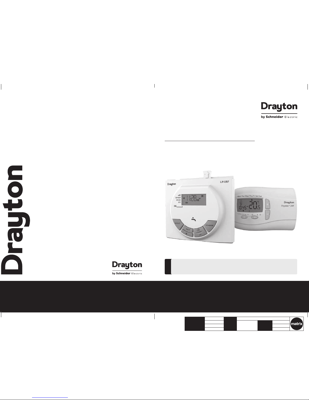
LP10RF & DIGISTAT+2RF
Radio frequency controlled pr ogrammable room
thermostat with domestic hot water programmer
Part number RF560DR
Installation & User Guide
06515086001 ISSE
For GREENS TAR CDi, GREENSTAR i JUNIOR an d GREENSTAR Si MODELS a lso
GREENSTAR i SYSTE M and GREENSTAR CDi SYS TEM MODEL(only when use d with
the optional i ntegral diver ter).
!
Spares P art numbe r 22090
Spares P art numbe r 22589D R
Support
401 Sou thway Drive
Plymouth
PL6 6QT
United Kingdom
Technical: +44(0)3 33 70 00 62 2
customer.care@draytoncontrols.co.uk
www.draytoncontrol s.co.uk
@DraytonHeating
/DraytonControls
Page 2
Client Drayton File Name 8443 Drayto n LP1 0RF & D IG IS TAT+2RF 06515086 001 I SSE
Artworker -
Proof Stage
02
Finished Size A5 148x210m m
Creative Director Mike Lane Artwork % 100%
Modification Date 27/04 /17 3: 30PM Bleed 3mm
Support Table of contents
PLEASE R EAD THESE IN STRUCTIO NS
CAREFULLY BEFORE STARTING.
These inst ructions are ap plicable to the
Drayton m odel(s) stated on the fron t
cover of this manu al only and must not
be used wit h any other make or mode l.
These inst ructions appl y in the UK only
and should be fo llowed except for any
statutory obligation.
If you are in any d oubt contact t he
Drayton technic al helpline.
This accessor y must be tted by a
competen t person. Failure t o comply
could lead to pr osecution.
Leave these i nstruction s with the user
or at the applia nce.
!
Abbreviations
CH = Central Heating
DHW = Domestic Hot Water
RF = Radio Frequency
DLS = Daylight S aving
BST = British Summer Time
GMT = G reenwich Mean Tim e
C = Cel sius (Centigrade)
IP = Ingres s Protection
V = Volt
m = metre
mA = milliAmpere
Denitions (DLS/BST)
Summer tim e begins: La st Sunday in Ma rch at
1:00 am GMT (Clock s are put for ward by 1 hour)
Summer time ends: Last Sunday in October at
2:00 am BST (Clo cks are put b ack by 1 hour)
Protect your environment
Proper battery recycling
Electro nic devices an d batteri es, recharge able or not,
should not b e disposed of i nto ordinary h ousehold w aste.
Instea d, they must be r ecycled pro perly to prot ect
the enviro nment and cut d own the wast e of precious
resourc es. Your local was te manageme nt authorit y
can supply d etails con cerning the pr oper dispo sal of
batteries.
Technical Data .............................................................................................................................. 2
In stallation Guide ..........................................................................................................3
LP10RF Installation ...................................................................................................... 4
Wireless Commissioning & Signal Strength ..................................................................5-6
Signal Strength ............................................................................................................ 7
Installer Options .......................................................................................................... 8-9
User Guide .......................................................................................................................10
DIGISTAT+2RF Room Thermostat .............................................................................................11
Controls a nd Display Lay out ...................................................................................... 12
Basic Settings .............................................................................................................. 13-15
User Options ...............................................................................................................15-19
Battery Change ........................................................................................................... 19
LP10RF P rogrammer & Rece iver ................................................................................................ 20
The Standa rd Program ................................................................................................ 21
Changing the Program ................................................................................................22-25
Maintenance ................................................................................................................................. 25
Symbols
Domest ic Hot Water
Radio Freq uency (RF ) Transmitter
401 Sou thway Drive
Plymouth
PL6 6QT
United Kingdom
Technical: +44(0)3 33 70 00 62 2
customer.care@draytoncontrols.co.uk
www.draytoncontrol s.co.uk
@DraytonHeating
/DraytonControls
1
Instal lation & User G uide LP 10 RF & D IG IS TAT+2R F
06515086001 ISSE
06515086001 ISSE
Page 3

Client Drayton File Name 8443 Drayto n LP1 0RF & D IG IS TAT+2RF 06515086 001 I SSE
Artworker -
Proof Stage
02
Finished Size A5 148x210m m
Creative Director Mike Lane Artwork % 100%
Modification Date 27/04 /17 3: 30PM Bleed 3mm
Digistat +2RF Transmitter
Thermostat
LP10RF Receiver
Dimensions 137mm x 96.5 mm x 31.3mm --
Power supply 2xA A 1.5V alk aline batte ries 24Vd.c. less than 65 mA
Radio frequency 433 MHz 433 MHz
Radio sign al range
30m typic ally. The rang e may be affe cted by the co mposition / d ensity and
number of wa lls betwe en the Digist at+2RF and LP10 RF.
Temperature range 5°C to 32°C --
Ambient operating temperature 0° C to +40°C 0°C to +50°C
Humidity operating range 25 - 90% non con densing up to
45°C
30 - 95% non cond ensing up to 45°C
Class of op eration -- II
Degrees of protection IP30 IP24
Control Accuracy +0.5°C @ 20°C Bette r than ±1 seco nd per day @ 25°C
Batte ry life (with alkal ine batteri es) approx. 2 yea rs N/A
Batte ry back up time an d date 10 years m in. 10 years min.
Shortest switching period 1 minute 1 minute
Hot water p re-heat set tings -- 3 ON / 3 OFF
Central heating settings 6 per day --
Energy Class IV = 2% (Acc. EU 81 1/2013, 812 /2013, 813/20 13, 814/201 3)
Pollution Class 2 2
Software Class A A
Ball pressure test 90°C 90°C
Software version 6712056 --
Max. radiated power +7.5 dB M (5.6mW) --
Technical Data
Installation Guide
LP10RF & DIGISTAT+2RF
Relevant EC Direc tives:
2014/53/EU RED Directive
2006/66/EC Battery Directive
2011/65/EU RoH S Directi ve
Applied Standards:
EN60730-1; EN607 30-2-7; EN60730-2-9
EN 300 220-2; EN 30 1 489-3
Pack Contents:
LP10R F Programme r / RF receive r
Digistat+2RF transmitter
Screw s (x2)
Wall Plugs (x2)
Instructions
Batte ries (x2) AA Alk aline
Hereby, S chneider Ele ctric Con trols UK L imited, decl ares that th is program mable room t hermost at is in compli ance
with the es sential re quiremen ts and othe r provisio ns of RED Dire ctive 201 4/53/EU.
Declara tion of confor mity can be d ownloaded a t: www.draytoncontrols.co.uk.
32
Instal lation & User G uide LP 10 RF & D IG IS TAT+2R F
06515086001 ISSE
06515086001 ISSE
Page 4
Client Drayton File Name 8443 Drayto n LP1 0RF & D IG IS TAT+2RF 06515086 001 I SSE
Artworker -
Proof Stage
02
Finished Size A5 148x210m m
Creative Director Mike Lane Artwork % 100%
Modification Date 27/04 /17 3: 30PM Bleed 3mm
NOTE:
This access ory must be tted by a compe tent person.
Failure to co mply could lead t o prosecut ion.
1.
Remove the b oiler outer c asing and cont rol panel
fascia to g ain access to th e boiler contr ol panel.
2.
Release th e securing scr ews.
3.
Pull the cov er panel up to re move.
4.
Grip the ta b and pull upwar ds to disenga ge clips,
pull forw ard to remov e blanking pl ate or exist ing
programmer.
5.
Align the con nector plu g pins into sock et on the
PCB and pu sh fully home.
6.
Feed the ri bbon cable int o the recess .
7.
Align the pr ogrammer an d locate the clip s, push
into the slot s then down to s ecure.
8.
Locate th e cover panel in p lace and secu re with
the scr ew.
9.
Replace f ascia cover and o uter casin g before
switchin g on the elect rical supply a nd boiler.
J
Switch bo iler on when comp leted.
CAUTION :
Isolate t he mains electrici ty supply
before st arting any work a nd observe
all relevan t safety precau tions.
Obser ve electro-st atic discharge
precauti ons: do not touch the p cb
circuit.
!
DANGE R:
230 volts d o not touch the elec trical
components or circuits.
F
Installation Guide LP10RF Programmer & Receiver Installation Guide LP10RF & DIGISTAT+2RF
Clips
Cover panel
Tab
Blanking
plate
Screw
Clips
Cover panel
Tab
Blanking
plate
Recess
LP10RF
Ribbon cable
Connector plug
Screw
Clips
Cover panel
Tab
Blanking
plate
Tab
Cover panel
Clips
Screw
LP10RF
Recess
LP10RF
Ribbon cable
Connector plug
Screw
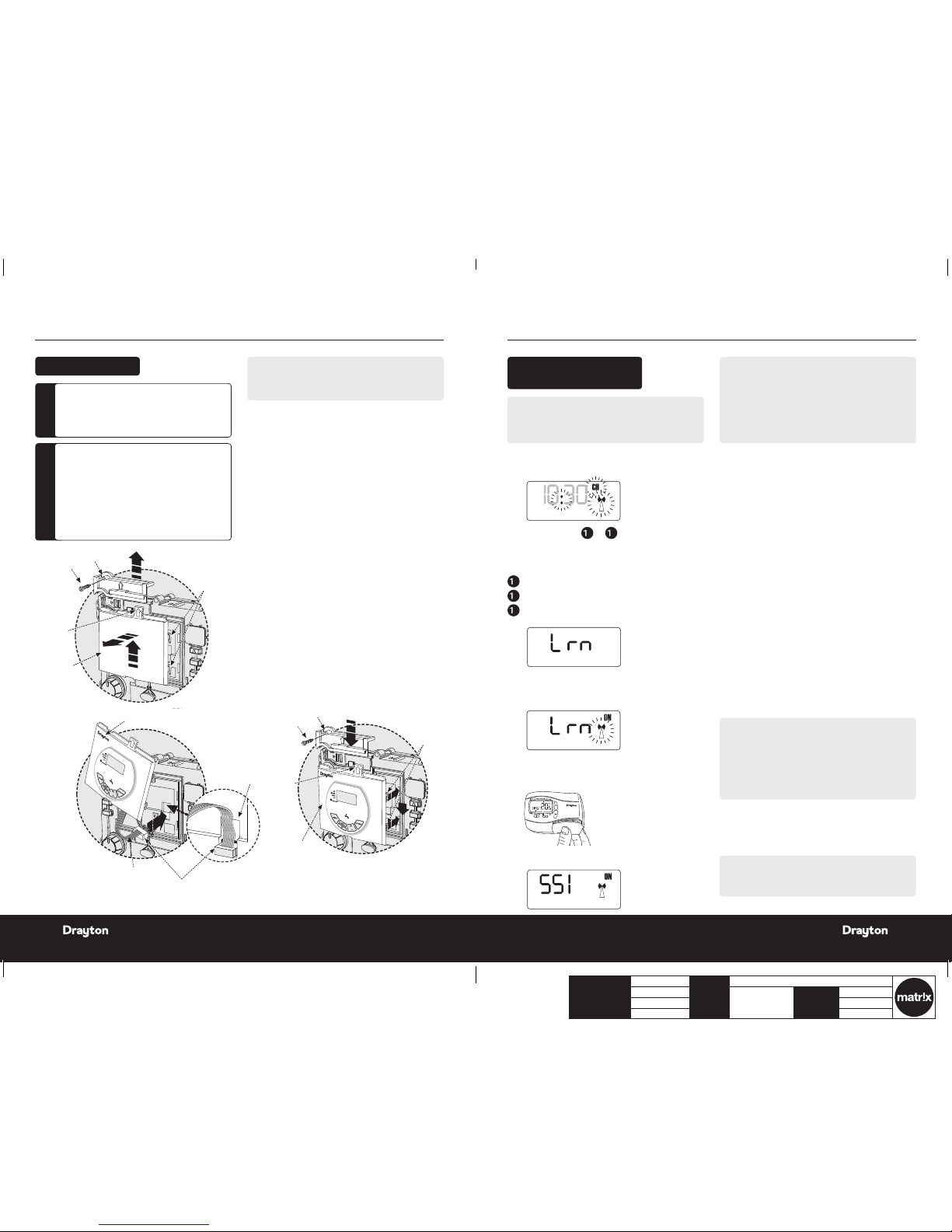
LP10RF Ins tallation
NOTE:
Before f ixing the D IGISTAT+2RF to the wa ll it is
recomme nded to fir st check th e signal str ength fro m
that location.
Wireless commissioning: after init ial star t up, the colon,
CH and antenna sym bols should be ashin g on the
LP10RF display.
Follow eith er 1 OR a to c below
1.
Press & hol d the set? butt on for 5s and Lrn an d
OFF will be d isplayed.
OR
a
Press the s et? button 4 ti mes.
b
Press the O K button o nce.
c
Press th e set? button 4 t imes; Lrn and OFF
will be displayed.
2.
Press the + b utton so th e display sho ws ON and a
ashing ant enna symbol. The learn mod e is now
ready to re ceive a signa l from the tran smitter
during the n ext two minu tes.
3. Take the Digi stat+2RF unit and s tand near th e
bo ile r.
4. Remo ve the battery cover and t the ba tteries.
5.
The symbol s on the LP10RF will stop as hing and
the displ ay will show ‘SS I, Antenna and O N’.
CLOCK?
10:30
OFF
CLOCK?
10:30
OFF
6.
Press ‘S ET’ on the LP10 RF and the dis play will
show ‘SSI a nd Antenna’.
7.
After a fe w seconds the d isplay will s how ‘- - -’.
Remove the batteries from the Digistat+2RF,
press and hold the ‘+’ butto n whilst rettin g the
batter ies, keep the ‘+’ butt on held and af ter a few
seconds t he display wi ll show ‘rF’ which indi cates
that the DI GISTAT+2RF is continu ously sendin g a
signal to th e LP10RF (rec eiver).
The LP10 RF display w ill now show the ‘le arnt’
transmit ter code and t he antenna’ as we ll as the
signal str ength as indi cated by the c hevrons on t he
right hand s ide of the displ ay.
H
Place the Digis tat+2RF in the desired nal pos ition
and retur n to the boiler to c heck the LP1 0RF
display . The ideal Digi stat+2RF posi tion will resu lt
in the LP10 RF displa y showing 4 chev rons and the
LED will be gr een.
I
If the LED is r ed or no LED is show ing and the
display indicates 1 or 2 chevrons, the Digistat+2RF
will need t o be re-positi oned until the L ED changes
to amber or gr een and 3 or 4 chev rons are indi cated
on the display.
NOTE:
If there is n o LED and the disp lay on the LP1 0RF shows
‘- - -’, there is n o signal being r eceived at al l from the
Digistat+2RF. Transmission will resume once the
Digist at+2RF is re-positi oned in a part o f the house
where an amb er or green LE D and 3 or 4 chevro ns
are achieved.
J
Once you ar e happy that, wh en in the desire d
location, th e Digista t+2RF is sending a goo d
signal to th e LP10RF i.e . amber or gree n and 3 or 4
chevron s, the Digistat+2RF can be xed to the wall .
CLOCK?
6:30
10:30
OFF
Wireless Commissioning
& Signal Strength
NOTE:
If you want t o exit to the h ome screen n ow without
checking t he signal st rength the n please pr ess the ‘OK /-’
button, t hen the ‘set?’ but ton. Altern atively, yo u can
leave for 2min s and the LP1 0RF will au tomatica lly
return to t he home scre en. See p.6 fo r how to mount
the Digis tat to the wa ll.
If you want t o check the sign al strengt h now, please
continue t o 6.
NOTE:
Contin ue on next pa ge to cancel t he signal str ength
mode.
54
Instal lation & User G uide LP 10 RF & D IG IS TAT+2R F
06515086001 ISSE
06515086001 ISSE
Page 5

Client Drayton File Name 8443 Drayto n LP1 0RF & D IG IS TAT+2RF 06515086 001 I SSE
Artworker -
Proof Stage
02
Finished Size A5 148x210m m
Creative Director Mike Lane Artwork % 100%
Modification Date 27/04 /17 3: 30PM Bleed 3mm
Installation Guide LP10RF & DIGISTAT+2RF Installation Guide LP10RF & DIGISTAT+2RF
LED Indication Chevrons RF Strength
Green 4 Very strong
Amber 3 Strong
Red 2 Weak
None 1 Very weak
To cancel signal strength mode:
1.
Remove the b atteries f rom the Digis tat+2RF to
cancel the constant transmission.
2.
After a fe w seconds the L P10RF dis play will
show ‘---’ .
3.
Press ‘OK’ o n the LP10R F and the displ ay will
return to t he time with th e ‘CH and Antenn a’
ashing.
4.
Re-inser t the batter ies into the Di gistat+2RF and
the RF link wi ll be re-est ablished.
Signal strength
indicators
Digistat+2RF code
(may be different)
LED indicator shows different colour depending
on signal strength (see table below)
Signal strength indicators
To check signal strength on previously
installed and paired units:
Follow eith er 1 OR a to c below
1.
Press & hol d the set? butt on for 10s and
‘SSI an d OFF’ will b e disp layed.
OR
a
Press the s et? button 4 ti mes.
b
Press the O K button o nce.
c
Press t he set? butto n 5 times; ‘SSI an d OFF’
will be displayed.
2.
Press the ‘+’ but ton so that th e display sho ws
‘SSI, Ant enna and ON’.
3.
Press the ‘s et’ butto n so the displa y shows
‘SSI and An tenna’.
OFF
OFF
OFF
Signal Strength
4.
After a fe w seconds the d isplay will s how ‘---’.
5.
Remove the b atteries f rom the Digis tat+2RF and
wait until t he display ha s faded away.
6.
Press and h old the ‘+’ button on t he Digist at+2RF
while re-inse rting the b atteries a nd keep the but ton
depres sed until the di splay show s ‘rF’ .
Mount the D igistat+2RF on a w all which is not su bject
to direct s unlight or dra ughts, prefe rably on an ins ide
wall, 1.5 metr es above the oor. The Digistat+2RF mus t
also not be direc tly inuenced by radia tors or other
appliance s giving of f heat.
Mounting the Digistat+2RF room thermostat
1.
Remove the fron t cover using a at screwdrive r and
separat e from back pla te.
Digistat+2RF
D
i
g
i
s
tat
+
2
R
F
D
i
g
i
s
tat
+
2
R
F
Digistat+2RF
D
i
g
i
s
t
a
t
+
2
R
F
D
i
g
i
s
tat
+
2
R
F
Digistat+2RF
2.
Fix the back p late direc tly onto the w all using the
allocate d xing points and suita ble wall plugs and
screws.
3.
Replace th e front cover b y locating in po sition and
pushing fu lly onto the ba ck cover.
4.
Remove the b attery cov er using a coin
To cancel signal strength mode:
1.
Remove the batteries from the Digistat+2RF
transmit ter to cance l the const ant transmis sion.
2.
After a fe w seconds the L P10RF dis play will sho w
‘---’ .
3.
Press ‘OK’ o n the LP10R F and the displ ay will
return to t he time with th e ‘CH and Antenn a’
ashing.
4.
Re-inser t the batter ies into the Di gistat+2RF
and the RF lin k will be re-est ablished.
5.
Instal l the 2 AA batt eries prov ided
6.
Replace battery cover
Digistat+2RF
D
i
g
i
s
t
a
t
+
2
R
F
LED Indication Chevrons RF Strength
Green 4 Very strong
Amber 3 Strong
Red 2 Weak
None 1 Very weak
Signal strength
indicators
Digistat+2RF code
(may be different)
LED indicator shows different colour depending
on signal strength (see table below)
Positioning the Digistat +2RF room thermostat
The Digis tat is a radio fr equency de vice which is ve ry
exible for pos itioning as there is no need for hard wir ing
to the appli ance. The devi ce should be mo unted in an
open area, no c loser than 30 cm from metal o bjects,
including wall boxes.
76
Instal lation & User G uide LP 10 RF & D IG IS TAT+2R F
06515086001 ISSE
06515086001 ISSE
Page 6

Client Drayton File Name 8443 Drayto n LP1 0RF & D IG IS TAT+2RF 06515086 001 I SSE
Artworker -
Proof Stage
02
Finished Size A5 148x210m m
Creative Director Mike Lane Artwork % 100%
Modification Date 27/04 /17 3: 30PM Bleed 3mm
Installation Guide DIGISTAT+2RF Installation Guide DIGISTAT+2RF
If enabled, t he start ti me should be se t an hour earlie r
than the tim e you want the pr operty t o reach the set
temperature.
Intellig ent Star t will delay th at start ti me, by an amount
that it has c alculated ba sed on the ac tual and set
temperature.
As the weat her become s milder, the start t ime is delay ed,
so that fue l is not waste d bringing the r oom up to
temperature earlier than necessar y.
The Digis tat calcula tes approxi mately 10 minu tes to raise
the tempe rature by 1°C , up to a maximum of 6°C .
NOTE:
Intellig ent Delay ed Start on ly applies in Auto mode.
Intellig ent Delay ed Start de fault is in OFF mode.
To switch ON Inte lligent Del ayed Star t enter the
Installer Options Menu (see Installer Options 06).
NOTE:
The Intel ligent Dela yed star t option is no t suitable fo r
under oor application . Ensure Installer op tion 06 is
set to OFF before n al commissioning for und eroor
application.
SPECIAL NOTE:
If the Inte lligent de layed star t feature i s enabled, (Of f
changed t o On in Insta ller option 0 6), please info rm
the end use r of this featu re.
The followi ng special n ote has been a dded to the us er
instruction to explain the adjustment requirement:
When the de lay period i s operating in dicated by t he
ame symbo l ashing, pressing any bu tton returns the
Digist at to auto mod e allowing norm al button op eration
until the ne xt time/ tem perature e vent, when it wil l
resume th e delay sta rt mode or fo llows the Holi day,
Manual, Ov erride or Of f modes as se lected.
Changes t o the install er options and p re-set prog rammes
must be made with the ame symbol not ashing .
Option 10 - Valve Protec tion
In some hea ting syste ms there may be a r equiremen t to
protec t the syste m by operatin g it once a day, for a gi ven
period.
If valve prot ection is s elected th e system wil l be operate d
for a perio d as shown in valve p rotectio n time (mins).
Valve protec tion time is eve ry day at 10.0 0am. Valve
protec tion default i s OFF.
To enable the valve pr otection m ode enter the I nstaller
Options Menu (Refer to Installer Option 10).
Option 11 - Valve Protec tion time (mins).
Valve protec tion time can b e set betwe en 1 and 5 minute s
(default 3 minut es).
To change this once a da y on time enter t he Install er
Options Menu (Refer to Installer Option 11).
Option 12 - App lication Type
Digist at+2RF can be used fo r differen t applicatio ns.
In the inst aller menu, se lect:
00 = Gas Boi ler
0 1 = Oil Boiler
Option 13- System Capability
Adjust thi s setting to s uit the heatin g system ca pability.
In the inst aller menu, se lect:
00 = Fast – the h ouse usuall y reaches se tpoint in ‹ 1 hour
0 1 = Slow – the hou se usually re aches setp oint in › 1 hour
Display Err or code E1
When the dis play shows a n error code (E 1) this indicat es
a sensor fa ult and the heati ng system w ill remain Of f.
Please con tact your lo cal heating s ervice en gineer to
replace y our Digist at +2RF.
Option 02 - Freeze Pro tection
Freeze prot ection wil l switch on the h eating if the ro om
tempera ture falls to 5° C and will then co ntrol the
tempera ture at 7°C eve n if the Digist at is in OFF mo de.
The Freeze Pr otection d efault is ON.
To switch off the Fr eeze Protec tion mode en ter the
Installer Options Menu (Refer to Installer Options 02)
and change t o OFF. Press to accept.
Option 04 & 0 5 - Low and High Limit
set points.
The user te mperature s et points d efaults are Hi gh 32°C
and Low 5°C, to ch ange these lim its enter th e Installe r
Options M enu (Refer to In staller Op tions 04 & 05).
Option 06 - Int elligent Delaye d Start
(Energy saving f eature).
The Intel ligent Dela yed Star t is an energy s aving featur e
which auto matically re duces the war m up time for the
heating system.
If you wish t o change any of th e Installe r Options as
shown in the t able below, ente r the Insta ller Option
Menu from A uto mode by pr essing: and +
simultaneously for 5 seconds.
Pressing and + again for 5 seconds will exit the
Menu and re turn to Auto mo de.
Once the In staller Op tions scree n has been sele cted,
the and buttons allow you to scroll
through t he Menu (shown be low). The + and - allow you
to change v alues.
Once a valu e has been chang ed pressing before
exiting the Menu will save the new setting. (The be low
display s hows Option 02 O FF).
Installer Options
Installer
Options
Function Sele ct
Option
Default
02 Freeze
protection
On Off On
04 Low Set
Point °C
5 High
Limit
5
05 High Set
Point °C
Low
Limit
32 32
06 Delayed
Start
(Energy
saving
feature)
On Off Off
10 Va lve
protection
On Off Off
11 Valve
protection
time (Mins)
1 5 3
12 Application
type
0 1 0
13 System
Capability
0 1 0
(* small 1 in lower half of screen
shows which time period is being set
e.g. 1=1st period, 2 = 2nd period etc)
(* small 1 in lower half of screen
shows which time period is being set
e.g. 1=1st period, 2 = 2nd period etc)
(* small 1 in lower half of screen
shows which time period is being set
e.g. 1=1st period, 2 = 2nd period etc)
(* small 1 in lower half of screen
shows which time period is being set
e.g. 1=1st period, 2 = 2nd period etc)
(* small 1 in lower half of screen
shows which time period is being set
e.g. 1=1st period, 2 = 2nd period etc)
(* small 1 in lower half of screen
shows which time period is being set
e.g. 1=1st period, 2 = 2nd period etc)
98
Instal lation & User G uide LP 10 RF & D IG IS TAT+2R F
06515086001 ISSE
06515086001 ISSE
Page 7

Client Drayton File Name 8443 Drayto n LP1 0RF & D IG IS TAT+2RF 06515086 001 I SSE
Artworker -
Proof Stage
02
Finished Size A5 148x210m m
Creative Director Mike Lane Artwork % 100%
Modification Date 27/04 /17 3: 30PM Bleed 3mm
User Guide
LP10RF & DIGISTAT+2RF
User Guide DIGIS TAT+2RF Room Thermos tat
DIGISTAT+2RF Room Thermostat
What is a programmable room thermostat?
...an explanation for householders
A program mable room the rmostat i s both a progr ammer
and a room th ermostat . A programm er allows you to s et
‘On’ and ‘Off ’ time perio ds to suit your o wn lifestyl e.
A room ther mostat wor ks by sensi ng the air
tempera ture, switchi ng on the heatin g when the air
tempera ture falls b elow the therm ostat set ting, and
switchin g it off once thi s set temper ature has be en
reached.
So, a progra mmable room th ermostat l ets you choo se
what times y ou want the he ating to be on, and w hat
tempera ture it shoul d reach while it is o n. It will allow
you to sele ct differ ent tempera tures in your h ome at
differe nt times of the da y (and days of the wee k) to meet
your par ticular nee ds.
Turning a program mable room the rmostat t o a higher
settin g will not make the r oom heat up any f aster. How
quickly th e room heats u p depends on th e design of
the heatin g system, for e xample, the size of b oiler and
radiators.
Neither d oes the set ting affec t how quickly th e room
cools dow n. Turning a programm able room ther mostat
to a lower set ting will re sult in the room b eing control led
at a lower temp erature, and s aves energ y.
The way to se t and use your p rogrammab le room
thermos tat is to nd the lowest tempe rature settin gs
that you ar e comforta ble with at the di fferent tim es you
have chose n, and then leave it a lone to do its jo b. The
best way to do this is to set low temp eratures rs t, say
18°C, and the n turn them up by o ne degree ea ch day until
you are comf ortable w ith the tempe ratures. You won’t
have to adju st the thermo stat fur ther. Any adjustm ents
above the se setting s will waste e nergy and cos t you more
money.
If your hea ting syste m is a boiler with r adiators,
there will u sually be onl y one program mable room
thermos tat to contr ol the whole ho use. But you c an
have diffe rent tempe ratures in ind ividual ro oms by
installing thermostatic radiator valves (TRVs) on
individu al radiator s. If you don’t hav e TRVs, you should
choose a te mperature t hat is reason able for the who le
house. If y ou do have TRVs, you ca n choose a sligh tly
higher set ting to make su re that even th e coldest roo m
is comfor table, then pr event any over heating in oth er
rooms by ad justing the T RVs.
The time on th e programme r must be corr ect. Some
types hav e to be adjust ed in spring and a utumn at the
changes b etween Gre enwich Mean T ime and Briti sh
Summer Time.
You may be able to te mporarily ad just the heat ing
program me, for example, ‘O verride’, ‘Advance’ or
‘Boost ’. These are explai ned in the manuf acturer’s
instructions.
Programm able room thermos tats need a free ow of air
to sense th e temperat ure, so they mus t not be covere d
by curt ains or blocked b y furniture . Nearby elec tric
res, telev isions, wall or table lamps ma y prevent the
thermostat from working properly.
Your Digistat +2RF
The Digis tat +2RF thermos tat is a prog rammable
thermos tat 24-Hour p roduct (the sa me program fo r
every day o f the week) which al lows you to se t up to 6
time and temperature events per day.
Clock Setting
Your Digistat +2RF is tte d with a real-time clock, which
is pre-set a t the factor y. You will not have to alt er the
time set tings. A spec ial feature of th is real-time clock is
to automa tically upda te the time duri ng the summer/
winter tim e change remov ing the need t o manually alte r
the clock.
General Operation
With the uni t in Auto mode (the sm all arrow to bo ttom
of screen wi ll point to Aut o) the temperatu re can be
changed fo r a short time b y using the + or - bu ttons.
Changing th e temperat ure in this way wi ll keep the
Digist at +2RF set to your ne w temperat ure until the ne xt
pre-prog rammed event (at wh ich time it will re vert to
programmed temperature). The temperature you are
settin g will ash on the screen. Once temp erature is set,
the unit will r evert to sh owing the curr ent temper ature.
The indica tor will show on t he screen if th e heating is
turned on.
A ashing ame indicates the produ ct is in intelligent
delayed start mode.
(* small 1 in lower half of screen
shows which time period is being set
e.g. 1=1st period, 2 = 2nd period etc)
(Fig 3)
How to replace the batteries see fig 3.
Remove the battery cover using a coin. Replace the spent
batteries with 2 x 1.5V IEC LR6 (AA) Alkaline batteries ensu ring
correct orientation. Replace the battery cover pressing fully home.
2. Once the time has been set
press to confirm and
use the + or – button to
adjust required temperature
(temperature shown flashing)
3. Once the temperature has
been set press to
confirm and move to the next
time and temperature periods
to be adjusted confirming
changes by pressing
button. (max 6 periods).
4. To exit press or
until you return to auto
mode with the bottom arrow
Drayton
Digistat +2RF
Digistat +2RF
Digistat +2RF
Digistat +2RF
Drayton
Drayton
Drayton
(* small 1 in lower half of screen
shows which time period is being set
e.g. 1=1st period, 2 = 2nd period etc)
How to replace the batteries see fig 3.
Remove the battery cover using a coin. Replace the spent
batteries with 2 x 1.5V IEC LR6 (AA) Alkaline batteries ensu ring
correct orientation. Replace the battery cover pressing fully home.
2. Once the time has been set
press to confirm and
use the + or – button to
adjust required temperature
(temperature shown flashing)
3. Once the temperature has
been set press to
confirm and move to the next
time and temperature periods
to be adjusted confirming
changes by pressing
button. (max 6 periods).
Drayton
Digistat +2RF
Digistat +2RF
Digistat +2RF
Digistat +2RF
Drayton
Drayton
Drayton
1110
Instal lation & User G uide LP 10 RF & D IG IS TAT+2R F
06515086001 ISSE
06515086001 ISSE
Page 8

Client Drayton File Name 8443 Drayto n LP1 0RF & D IG IS TAT+2RF 06515086 001 I SSE
Artworker -
Proof Stage
02
Finished Size A5 148x210m m
Creative Director Mike Lane Artwork % 100%
Modification Date 27/04 /17 3: 30PM Bleed 3mm
Controls and Display Layout
Drayton
Digistat
+2
RF
+ or - buttons
for setting
adjustments
Clock
mode
RH (right hand)
button, moves the
pointer to the right,
selects and accepts
changes
Time/Temperature
Program events 1 to 6
in sequence, morning,
midday and night
LH (left hand) button,
moves the pointer to
the left for selection
Holiday,
Manual, Auto,
Day, Program
Pointer
(mode
indicator)
Time
Flame shows when
calling for heat
Pointer (day)
Days
Temperature
NOTE:
Temperature displayed is actual room temperature
unless adj usting the + or - b utton whe n it display s
the set tem perature. O nce adjustm ent is comple te
and afte r 5 seconds this w ill return to a ctual room
temperature.
User Guide DIGIS TAT+2RF Room Thermos tat
Basic Settin gs
The Digis tat +2RF thermos tat is a prog rammable
thermos tat 24-Hour (th e same progra m for every day o f
the week) and a llows you to se t 6 time and temp erature
events per day.
Digistat +2RF P re-set Program
Your Digista t +2RF comes with the f ollowing defa ult
settin gs pre-progr ammed for you r convenience:
Pre-set Prog ram 1 (9 til 5)
As you can s ee, at 06:30 , the he ating will come o n
to raise th e temperatu re to 20ºC . At 08:30, the
tempera ture set poin t is dropped f rom 20ºC dow n
to 16ºC, it s tays at 16º C througho ut the day, until
16:30 when t he temperat ure increas es to 21ºC . The
tempera ture then dro ps down to a night-se tback
tempera ture of 7ºC un til 06:30 when th e cycle repea ts
for the nex t day.
Event 1 2 3 4 5 6
Time 6:3 0 8:30 12:0 0 14:00 16: 30 22:30
Tem p 20.0 16.0 16.0 1 6.0 21.0 7.0
1234 5 6
25°C
20°C
06:30 08:30 12:00 14:00 16:30 22:30
Time Period
Room Temp
15°C
10°C
5°C
To adjust these times and te mperatures
1.
With the pr oduct oper ating as norm al in the Auto
mode press twice until the displ ay is ashing
as shown. The time will be as hing, use the + or -
button s to adjust th e 1st time as re quired.
2.
Once the time has been set press to conrm
and use the + o r – button to a djust req uired
temperature (temperature shown required ashing).
3.
Once the te mperature h as been set pr ess
to conrm and move to the nex t time and
tempera ture periods to be adjus ted conrming
changes b y pressing bu tton. (max 6
periods).
4.
To exit press or un til you retur n to
auto mode w ith the bot tom chevron p ointing to
aut o (as sho wn).
(* small 1 in lower half of screen
shows which time period is being set
e.g. 1=1st period, 2 = 2nd period etc)
(* small 1 in lower half of screen
shows which time period is being set
e.g. 1=1st period, 2 = 2nd period etc)
(* small 1 in lower half of screen
shows which time period is being set
e.g. 1=1st period, 2 = 2nd period etc)
(* small 1 in lower half of screen
shows which time period is being set
e.g. 1=1st period, 2 = 2nd period etc)
(* small 1 in lower half of screen
shows which time period is being set
e.g. 1=1st period, 2 = 2nd period etc)
(* small 1 in lower half of screen
shows which time period is being set
e.g. 1=1st period, 2 = 2nd period etc)
(* small 1 in lower half of screen
(* small 1 in lower half of screen
(* small 1 in lower half of screen
shows which time period is being set
e.g. 1=1st period, 2 = 2nd period etc)
Congratulations!
The unit is now set correctly to follow your required timings.
To set a constant room temperature (Manual mode):
1. Press once, the display
shows temperature flashing
(example
20 0C)
2. Press + or - buttons to
adjust the temperature as
required. The temperature
will stop flashing after 5
seconds and start controlling
at this temperature
3. To exit manual mode press
once, to return to auto.
To change temperature for a short period (Override):
1. Press + or - buttons to
adjust set temperature. Set
temperature shown flashing
2. After 5 seconds will start
controlling at selected set
point but displays actual room
temperature. 2 chrevons
indicates override mode.
3. To exit override press
once or wait until next change
in the pre-set program.
2. Once the time has been set
press to confirm and
use the + or – button to
adjust required temperature
(temperature shown flashing)
3. Once the temperature has
been set press to
confirm and move to the next
time and temperature periods
to be adjusted confirming
changes by pressing
button. (max 6 periods).
4. To exit press or
until you return to auto
mode with the bottom arrow
pointing to auto (as shown).
Digistat +2RF
Digistat +2RF
Drayton
Drayton
User Guide DIGIS TAT+2RF Room Thermos tat
NOTE:
The above se ttings ca n be underst ood using th e
chart be low
NOTE:
The small 1 in th e lower half of the s creen shows w hich
time perio d is being set e. g. 1=1st pe riod, 2 = 2nd
period, etc.
1312
Instal lation & User G uide LP 10 RF & D IG IS TAT+2R F
06515086001 ISSE
06515086001 ISSE
Page 9

Client Drayton File Name 8443 Drayto n LP1 0RF & D IG IS TAT+2RF 06515086 001 I SSE
Artworker -
Proof Stage
02
Finished Size A5 148x210m m
Creative Director Mike Lane Artwork % 100%
Modification Date 27/04 /17 3: 30PM Bleed 3mm
To change temperature for a s hort period
(Ov erri de)
1.
Press + or - b uttons to ad just set te mperature.
Set temper ature shown ashin g.
2.
After 5 se conds the Dig istat+2RF will s tart
controll ing at the selec ted setpo int but the disp lay
shows the a ctual room t emperatur e. 2 chevrons
indicates override mode.
3.
To exit override p ress once or w ait until
next cha nge in the pre-s et program.
(* small 1 in lower half of screen
shows which time period is being set
e.g. 1=1st period, 2 = 2nd period etc)
To set a constant room temp erature
(Manual mode)
1.
Press onc e, the display s hows temper ature
ashing (examp le 20.0°C).
(* small 1 in lower half of screen
shows which time period is being set
e.g. 1=1st period, 2 = 2nd period etc)
(* small 1 in lower half of screen
shows which time period is being set
e.g. 1=1st period, 2 = 2nd period etc)
2.
Press + or - b uttons to ad just the tem perature as
require d. The temperature wil l stop ashing afte r
5 seconds a nd start co ntrolling at t his tempera ture.
3.
To exit manual mod e press once, to r eturn
to auto.
User Guide DIGIS TAT+2RF Room Thermos tat
To set holiday mode:
1.
Press twice, the display shows time a shing.
Time perio ds betwe en 1 to 23(Hr)hour s and 1 to
199(d)days can b e set.
2.
Press + or - b uttons to ad just the coun t down
time as require d. Press once to conrm, the
display wil l show temperature a shing.
3.
Press + or - b uttons to ad just tempe rature and
press to s tart holi day count dow n time.
Alternati vely afte r 10 seconds t he tempera ture
will stop ash ing and holiday count down time wil l
star t. Display s hows count dow n time and ambie nt
room temperature.
4.
To exit the holida y mode press o r
once, to retu rn to auto.
(* small 1 in lower half of screen
shows which time period is being set
e.g. 1=1st period, 2 = 2nd period etc)
(* small 1 in lower half of screen
shows which time period is being set
e.g. 1=1st period, 2 = 2nd period etc)
(* small 1 in lower half of screen
shows which time period is being set
e.g. 1=1st period, 2 = 2nd period etc)
(* small 1 in lower half of screen
shows which time period is being set
e.g. 1=1st period, 2 = 2nd period etc)
(* small 1 in lower half of screen
shows which time period is being set
e.g. 1=1st period, 2 = 2nd period etc)
(Option 01)
How to change from 24hr to 12hr clock.
Enter user options, select option 01 and use + and – keys to select
desired option, 12 = 12hr and 24 = 24hr. Press > to accept change.
(Option 02)
How to change to another predefined program 1, 2 or 3.
Enter user options, select option 02 and use + and – keys to
select desired program 1, 2 or 3. 1 = program 1, 2 = program 2
Date and time setting.
Digistat +2RF comes with a pre-set clock, which also
automatically adjusts for summer/winter time changes. It is
activated automatically on 1st installation. There should be no
need to change these settings, however, should you wish to, it
can be done in Option 05.
(Option 05)
How to adjust date and time.
(Option 09)
How to lock the key pad - Access Protection Lock.
The access protection lock allows you to lock the Digistat +2RF so
that it cannot have any adjustments.
The default is OFF mode allowing you to adjust the Digistat +2RF.
To Lock the Digistat +2RF settings enter the User Options Menu
Option 09 and select On and press > to accept .
Once the User Options Menu is exited all buttons will be locked.
(Option 01)
How to change from 24hr to 12hr clock.
Enter user options, select option 01 and use + and – keys to select
desired option, 12 = 12hr and 24 = 24hr. Press > to accept change.
(Option 02)
How to change to another predefined program 1, 2 or 3.
Enter user options, select option 02 and use + and – keys to
select desired program 1, 2 or 3. 1 = program 1, 2 = program 2
and 3 = program 3. Press > to accept desired change.
Preset programs 2 and 3 are shown below:
Event 1 2 3 4 5 6
Time 6:30 8:30 12:00 14:00 16:30 22:30
Pre-set Program 2. (Home for Lunch)
Date and time setting.
Digistat +2RF comes with a pre-set clock, which also
automatically adjusts for summer/winter time changes. It is
activated automatically on 1st installation. There should be no
need to change these settings, however, should you wish to, it
can be done in Option 05.
(Option 05)
How to adjust date and time.
Enter user options, select option 05 (fig 6)
To change the year press > once (fig 7)
To change the month press > again (fig 8)
To change the day press > again (fig 9)
To change the time press > again (fig 10)
Once you have selected your required display, to adjust press
+ or - and > to accept change.
To select option 06 press > until option 06 display is shown
(Option 09)
How to lock the key pad - Access Protection Lock.
The access protection lock allows you to lock the Digistat +2RF so
that it cannot have any adjustments.
The default is OFF mode allowing you to adjust the Digistat +2RF.
To Lock the Digistat +2RF settings enter the User Options Menu
Option 09 and select On and press > to accept .
Once the User Options Menu is exited all buttons will be locked.
To switch off the Protection Lock enter the User Menu and change
to OFF. Press > to accept.
Once the User Menu is exited all buttons will be free to adjust.
Special Note:
The following only applies when the Intelligent delayed start
(Option 01)
How to change from 24hr to 12hr clock.
Enter user options, select option 01 and use + and – keys to select
desired option, 12 = 12hr and 24 = 24hr. Press > to accept change.
(Option 02)
How to change to another predefined program 1, 2 or 3.
Enter user options, select option 02 and use + and – keys to
select desired program 1, 2 or 3. 1 = program 1, 2 = program 2
and 3 = program 3. Press > to accept desired change.
Preset programs 2 and 3 are shown below:
Event 1 2 3 4 5 6
Time 6:30 8:30 12:00 14:00 16:30 22:30
Temperature 21.0 16.0 21.0 16.0 21.0 10.0
*The above settings can be understood using the chart below
25ºC
20ºC
15ºC
Pre-set Program 2. (Home for Lunch)
Date and time setting.
Digistat +2RF comes with a pre-set clock, which also
automatically adjusts for summer/winter time changes. It is
activated automatically on 1st installation. There should be no
need to change these settings, however, should you wish to, it
can be done in Option 05.
(Option 05)
How to adjust date and time.
Enter user options, select option 05 (fig 6)
To change the year press > once (fig 7)
To change the month press > again (fig 8)
To change the day press > again (fig 9)
To change the time press > again (fig 10)
Once you have selected your required display, to adjust press
+ or - and > to accept change.
To select option 06 press > until option 06 display is shown
(fig 11)
(Option 09)
How to lock the key pad - Access Protection Lock.
The access protection lock allows you to lock the Digistat +2RF so
that it cannot have any adjustments.
The default is OFF mode allowing you to adjust the Digistat +2RF.
To Lock the Digistat +2RF settings enter the User Options Menu
Option 09 and select On and press > to accept .
Once the User Options Menu is exited all buttons will be locked.
To switch off the Protection Lock enter the User Menu and change
to OFF. Press > to accept.
Once the User Menu is exited all buttons will be free to adjust.
Special Note:
The following only applies when the Intelligent delayed start
feature is enabled by the installer.
When the delay period is operating indicated by the flame symbol
flashing (Fig12), pressing any button returns the Digistat +2RF to
auto mode allowing normal button operation until the next time/
temperature event, when it will resume the delay start mode or
follows the Holiday, Manual, Override or Off modes as selected.
Changes to the installer options and pre-set programmes must be
(Option 01)
How to change from 24hr to 12hr clock.
Enter user options, select option 01 and use + and – keys to select
desired option, 12 = 12hr and 24 = 24hr. Press > to accept change.
(Option 02)
How to change to another predefined program 1, 2 or 3.
Enter user options, select option 02 and use + and – keys to
select desired program 1, 2 or 3. 1 = program 1, 2 = program 2
and 3 = program 3. Press > to accept desired change.
Preset programs 2 and 3 are shown below:
Event 1 2 3 4 5 6
Time 6:30 8:30 12:00 14:00 16:30 22:30
Temperature 21.0 16.0 21.0 16.0 21.0 10.0
*The above settings can be understood using the chart below
123456
25ºC
20ºC
15ºC
10ºC
5ºC
06:30 08:30 12:00 14:00 16:30 22:30
Time Period
Room Temp
Pre-set Program 2. (Home for Lunch)
Date and time setting.
Digistat +2RF comes with a pre-set clock, which also
automatically adjusts for summer/winter time changes. It is
activated automatically on 1st installation. There should be no
need to change these settings, however, should you wish to, it
can be done in Option 05.
(Option 05)
How to adjust date and time.
Enter user options, select option 05 (fig 6)
To change the year press > once (fig 7)
To change the month press > again (fig 8)
To change the day press > again (fig 9)
To change the time press > again (fig 10)
Once you have selected your required display, to adjust press
+ or - and > to accept change.
To select option 06 press > until option 06 display is shown
(fig 11)
(Fig 6)
As you can see, at 06:30, the heating will come on to raise the
(Option 09)
How to lock the key pad - Access Protection Lock.
The access protection lock allows you to lock the Digistat +2RF so
that it cannot have any adjustments.
The default is OFF mode allowing you to adjust the Digistat +2RF.
To Lock the Digistat +2RF settings enter the User Options Menu
Option 09 and select On and press > to accept .
Once the User Options Menu is exited all buttons will be locked.
To switch off the Protection Lock enter the User Menu and change
to OFF. Press > to accept.
Once the User Menu is exited all buttons will be free to adjust.
Special Note:
The following only applies when the Intelligent delayed start
feature is enabled by the installer.
When the delay period is operating indicated by the flame symbol
flashing (Fig12), pressing any button returns the Digistat +2RF to
auto mode allowing normal button operation until the next time/
temperature event, when it will resume the delay start mode or
follows the Holiday, Manual, Override or Off modes as selected.
Changes to the installer options and pre-set programmes must be
made with the flame symbol not flashing.
To switch OFF the thermostat:
Press the + a nd – simultane ously for 5 se conds until th e
OFF is displayed.
The thermo stat and he ating syste m will now be OF F
unless the t emperatu re in the contro lled space fal ls
below 7°C, t he frost pro tection se t point. Plea se note this
does not af fect the op eration of the d omestic ho t water
where provided.
To switch ON the the rmostat, p ress any key t o return to
auto mode .
User Guide DIGIS TAT+2RF Room Thermos tat
User Options
If you wish t o change any Us er Options (show n in table
on next p age) they can be ac cessed fro m Auto or Man
by press ing and simulta neously for 3
seconds . Once you have a ccessed th e User Option s Menu
(Fig 1) pre ss to scroll th rough selec table opti ons.
The sett ings for each op tion can be chan ged by pres sing
+ or - as requir ed. Press to a ccept the chan ge and
move to the ne xt option . To exit press and
simultaneously for 3 seconds. Alternatively, not pressing
any butt ons for 2 mins will c ause the Dig istat +2RF to
return to A uto. (Fig 2) show s option 01 24 (24 ho ur
clock).
Only sele cted optio ns that have bee n accepted b y
pressing will be changed.
shows time flashing
Time periods between 1 to
23(Hr)hours and 1 to
199(d)days can be set.
adjust the count down time
as required. Press once
to confirm, the display will
show temperature flashing.
adjust temperature and press
to start holiday count
down time. Alternatively after
10 seconds the temperature
will stop flashing and holiday
count down time will start .
Display shows count down
time and ambient room
temperature.
press the or
once, to return to auto.
(Option 01)
How to change from 24hr to 12hr clock.
Enter user options, select option 01 and use + and – keys to select
desired option, 12 = 12hr and 24 = 24hr. Press > to accept change.
(Option 02)
How to change to another predefined program 1, 2 or 3.
Enter user options, select option 02 and use + and – keys to
select desired program 1, 2 or 3. 1 = program 1, 2 = program 2
and 3 = program 3. Press > to accept desired change.
Preset programs 2 and 3 are shown below:
Event 1 2 3 4 5 6
Time 6:30 8:30 12:00 14:00 16:30 22:30
Temperature 21.0 16.0 21.0 16.0 21.0 10.0
*The above settings can be understood using the chart below
123456
25ºC
20ºC
15ºC
10ºC
5ºC
06:30 08:30 12:00 14:00 16:30 22:30
Time Period
Room Temp
Event 1 2 3 4 5 6
Time 6:00 8:30 12:00 14:00 17:30 22:30
Temperature 21.0 19.0 21.0 19.0 21.0 16.0
*The above settings can be understood using the chart below
123456
25ºC
20ºC
15ºC
10ºC
5ºC
06:00 08:30 12:00 14:00 17:30 22:30
Time Period
Room Temp
Pre-set Program 2. (Home for Lunch)
Pre-set Program 3. (Home Worker)
Date and time setting.
Digistat +2RF comes with a pre-set clock, which also
automatically adjusts for summer/winter time changes. It is
activated automatically on 1st installation. There should be no
need to change these settings, however, should you wish to, it
can be done in Option 05.
(Option 05)
How to adjust date and time.
Enter user options, select option 05 (fig 6)
To change the year press > once (fig 7)
To change the month press > again (fig 8)
To change the day press > again (fig 9)
To change the time press > again (fig 10)
Once you have selected your required display, to adjust press
+ or - and > to accept change.
To select option 06 press > until option 06 display is shown
(fig 11)
(Option 06)
How to change temperature offset .
The temperature displayed on the thermostat may not match
that of other temperature measuring devices in the controlled
space, because of its location. The displayed temperature may
be offset to bring it in line with other devices. To adjust the
temperature, enter the user options, select option 06. The
temperature may be offset by +/- 5 degrees by pressing the
+ and – keys. Press > to accept the desired change.
(Option 07)
How to restore the built in time temperature programs.
(Fig 10)(Fig 9)
(Fig 8)(Fig 7)
(Fig 6)
(Fig 11)
As you can see, at 06:30, the heating will come on to raise the
temperature to 21°C.
At 08:30, the temperature set point is dropped to 16°C, it stays at
16°C until 12:00 when the heating comes on to raise the
temperature to 21°C. The temperature stays at 21°C until 14:00
when it drops to 16°C. At 16:30 the heating comes on to raise the
temperature to 21°C where it stays until 22:30 when the
temperature drops down to a setback temperature of 10°C until
06:30 when the cycle repeats the next day.
As you can see, at 06:00, the heating will come on to raise the
temperature to 21°C.
At 08:30, the temperature set point is dropped to 19°C, it stays at
19°C until 12:00 when the heating comes on to raise the
(Option 09)
How to lock the key pad - Access Protection Lock.
The access protection lock allows you to lock the Digistat +2RF so
that it cannot have any adjustments.
The default is OFF mode allowing you to adjust the Digistat +2RF.
To Lock the Digistat +2RF settings enter the User Options Menu
Option 09 and select On and press > to accept .
Once the User Options Menu is exited all buttons will be locked.
To switch off the Protection Lock enter the User Menu and change
to OFF. Press > to accept.
Once the User Menu is exited all buttons will be free to adjust.
Special Note:
The following only applies when the Intelligent delayed start
feature is enabled by the installer.
When the delay period is operating indicated by the flame symbol
flashing (Fig12), pressing any button returns the Digistat +2RF to
auto mode allowing normal button operation until the next time/
temperature event, when it will resume the delay start mode or
follows the Holiday, Manual, Override or Off modes as selected.
Changes to the installer options and pre-set programmes must be
made with the flame symbol not flashing.
What is Intelligent delayed start?
Intelligent Delayed Start (Energy saving feature)
The Intelligent Delayed Start is an energy saving feature which
automatically reduces the warm up time for the heating system. As
the weather becomes milder, Intelligent Start will delay the heating
start times so that the fuel is not wasted bringing the room up to
temperature earlier than necessary.
(Fig 12)
Fig 1
Fig 2
(* small 1 in lower half of screen
shows which time period is being set
e.g. 1=1st period, 2 = 2nd period etc)
(* small 1 in lower half of screen
shows which time period is being set
e.g. 1=1st period, 2 = 2nd period etc)
(* small 1 in lower half of screen
shows which time period is being set
e.g. 1=1st period, 2 = 2nd period etc)
(* small 1 in lower half of screen
shows which time period is being set
e.g. 1=1st period, 2 = 2nd period etc)
(* small 1 in lower half of screen
shows which time period is being set
e.g. 1=1st period, 2 = 2nd period etc)
(* small 1 in lower half of screen
shows which time period is being set
e.g. 1=1st period, 2 = 2nd period etc)
(* small 1 in lower half of screen
shows which time period is being set
e.g. 1=1st period, 2 = 2nd period etc)
1514
Instal lation & User G uide LP 10 RF & D IG IS TAT+2R F
06515086001 ISSE
06515086001 ISSE
Page 10

Client Drayton File Name 8443 Drayto n LP1 0RF & D IG IS TAT+2RF 06515086 001 I SSE
Artworker -
Proof Stage
02
Finished Size A5 148x210m m
Creative Director Mike Lane Artwork % 100%
Modification Date 27/04 /17 3: 30PM Bleed 3mm
User Options What is it Min Max Default
01 Change 12 h or 24h clock 12 24 24
02
Change to another pre-set
programme
1 3 1
03
Change the n umber of
programme events per day
2, 4 or 6 6
04
Switch on/off automatic
summer/winter time change
On Off On
05 Adjus t date and time Factory S et
06 Change t emperatur e offset °C -5 5 0
07 Restore pre-set programme On Off Off
08 To disable Of f function On Off On
09 Access protection lock On Off Off
Option 01 - How t o change from 24hr to
12hr clock
Enter use r options, sele ct option 0 1 and use + and – key s
to selec t desired opt ion, 12 = 12hr and 24 = 24hr. Press
to accept ch ange.
Option 02 - How to ch ange to another
predene d program 1, 2 or 3
Enter use r options, sele ct option 02 and u se + and – keys
to selec t desired pro gram 1, 2 or 3. 1 = pro gram 1, 2 =
program 2 a nd 3 = program 3. P ress to acce pt
desired change.
Pre-set Prog rams 2 and 3 are shown below:
Pre-set Prog ram 2 (Home for Lunch)
Event 1 2 3 4 5 6
Time 6:3 0 8:30 12:0 0 14:00 16: 30 22:30
Tem p 21 .0 16.0 21.0 16.0 21 .0 10.0
25°C
20°C
Room Temp
15°C
10°C
5°C
1234 5 6
06:30 08:30 12:00 14:00 16:30 22:30
Time Period
As you can s ee, at 06:30, the hea ting will come on t o
raise the temperature to 21°C.
At 08:30, the tem perature se t point is drop ped to 16°C,
it stay s at 16°C until 12:00 w hen the heatin g comes on to
raise the temperature to 21°C. The temperature stays
at 21°C unti l 14:00 when it dr ops to 16°C. At 16: 30, the
heating co mes on to raise t he temperat ure to 21°C wh ere
it stay s until 22:30, whe n the temper ature drops d own
to a setbac k temperatu re of 10°C until 0 6:30, when the
cycle repe ats the nex t day.
User Guide DIGIS TAT+2RF Room Thermos tat
NOTE:
The above se ttings ca n be underst ood using th e
chart to th e right.
User Guide DIGIS TAT+2RF Room Thermos tat
Pre-set Prog ram 3 (Home Worker)
As you can s ee, at 06:00, the hea ting will come o n to
raise the temperature to 21°C.
At 08:30, the tem perature se t point is drop ped to 19°C,
it stay s at 19°C until 12: 00 when the he ating comes on t o
raise the temperature to 21°C. The temperature stays
at 21°C unti l 14:00 when it dr ops to 19°C . At 17:30, the
heating co mes on to raise t he temperat ure to 21°C wh ere
it stay s until 22:30, whe n the temper ature drops d own
to a setbac k temperatu re of 16°C until 06:0 0, when the
cycle repe ats the nex t day.
Option 03 - How to ch ange the number of
program event s per day
Enter use r options, sele ct option 03 an d use + and – keys
to selec t desired opt ion. 2 = 2 time / temp e vents per da y,
4 = 4 time / temp ev ents per day a nd 6 = 6 time / temp
events p er day. Pres s to accept des ired change.
Event 1 2 3 4 5 6
Time 6:00 8:30 12:00 1 4:00 17: 30 22:30
Tem p 21 .0 19.0 21.0 1 9.0 21.0 16.0
25°C
20°C
Room Temp
15°C
10°C
5°C
1234 5 6
06:00 08:30 12:00 14:00 17:30 22:30
Time Period
Option 04 - How t o switch on/off the
automatic summ er / winter time change
Twice a year the act ual time is aut omatically c hanged
to keep it in lin e with the summ er / winter time c hange.
Default se tting is On. I f you wish to dis able / enable th is
feature en ter user opt ions, selec t option 04 and p ress –
or + key to disp lay Off or O n as desired. P ress to
accept desired change.
NOTE:
Date and tim e setting.
Digist at +2RF comes with a pr e-set clock, wh ich
also auto matically ad justs for su mmer/winter
time change s. It is acti vated auto matically o n 1st
install ation. Ther e should be no ne ed to change th ese
settin gs, however, should yo u wish to, it can be do ne
in Option 0 5.
Option 05 - How t o adjust date and time
Enter use r options, sele ct option 05 ( Fig 3)
To change the year press once (g 4)
To change the month press again (g 5)
To change the day press again (g 6)
To change the time press again (g 7)
Once you hav e selecte d your requir ed display, to a djust
press + or - an d to accept chan ge.
To select option 0 6 press until o ption 06 disp lay
is shown (g 8)
Date and time setting.
Digistat +2RF comes with a pre-set clock, which also
automatically adjusts for summer/winter time changes. It is
activated automatically on 1st installation. There should be no
need to change these settings, however, should you wish to, it
can be done in Option 05.
(Option 05)
How to adjust date and time.
Enter user options, select option 05 (fig 6)
To change the year press > once (fig 7)
To change the month press > again (fig 8)
To change the day press > again (fig 9)
To change the time press > again (fig 10)
Once you have selected your required display, to adjust press
+ or - and > to accept change.
To select option 06 press > until option 06 display is shown
(fig 11)
(Option 09)
How to lock the key pad - Access Protection Lock.
The access protection lock allows you to lock the Digistat +2RF so
that it cannot have any adjustments.
The default is OFF mode allowing you to adjust the Digistat +2RF.
To Lock the Digistat +2RF settings enter the User Options Menu
Option 09 and select On and press > to accept .
Once the User Options Menu is exited all buttons will be locked.
To switch off the Protection Lock enter the User Menu and change
to OFF. Press > to accept.
Once the User Menu is exited all buttons will be free to adjust.
Special Note:
The following only applies when the Intelligent delayed start
feature is enabled by the installer.
When the delay period is operating indicated by the flame symbol
flashing (Fig12), pressing any button returns the Digistat +2RF to
auto mode allowing normal button operation until the next time/
temperature event, when it will resume the delay start mode or
follows the Holiday, Manual, Override or Off modes as selected.
Changes to the installer options and pre-set programmes must be
Fig 3
Fig 4
Date and time setting.
Digistat +2RF comes with a pre-set clock, which also
automatically adjusts for summer/winter time changes. It is
activated automatically on 1st installation. There should be no
need to change these settings, however, should you wish to, it
can be done in Option 05.
(Option 05)
How to adjust date and time.
Enter user options, select option 05 (fig 6)
To change the year press > once (fig 7)
To change the month press > again (fig 8)
To change the day press > again (fig 9)
To change the time press > again (fig 10)
Once you have selected your required display, to adjust press
+ or - and > to accept change.
To select option 06 press > until option 06 display is shown
(fig 11)
(Fig 6)
(Option 09)
How to lock the key pad - Access Protection Lock.
The access protection lock allows you to lock the Digistat +2RF so
that it cannot have any adjustments.
The default is OFF mode allowing you to adjust the Digistat +2RF.
To Lock the Digistat +2RF settings enter the User Options Menu
Option 09 and select On and press > to accept .
Once the User Options Menu is exited all buttons will be locked.
To switch off the Protection Lock enter the User Menu and change
to OFF. Press > to accept.
Once the User Menu is exited all buttons will be free to adjust.
Special Note:
The following only applies when the Intelligent delayed start
feature is enabled by the installer.
When the delay period is operating indicated by the flame symbol
flashing (Fig12), pressing any button returns the Digistat +2RF to
auto mode allowing normal button operation until the next time/
temperature event, when it will resume the delay start mode or
follows the Holiday, Manual, Override or Off modes as selected.
Changes to the installer options and pre-set programmes must be
made with the flame symbol not flashing.
NOTE:
The above se ttings ca n be underst ood using th e
char t below.
(* small 1 in lower half of screen
shows which time period is being set
e.g. 1=1st period, 2 = 2nd period etc)
(* small 1 in lower half of screen
shows which time period is being set
e.g. 1=1st period, 2 = 2nd period etc)
(* small 1 in lower half of screen
shows which time period is being set
e.g. 1=1st period, 2 = 2nd period etc)
(* small 1 in lower half of screen
shows which time period is being set
e.g. 1=1st period, 2 = 2nd period etc)
(* small 1 in lower half of screen
shows which time period is being set
e.g. 1=1st period, 2 = 2nd period etc)
(* small 1 in lower half of screen
shows which time period is being set
e.g. 1=1st period, 2 = 2nd period etc)
(* small 1 in lower half of screen
shows which time period is being set
e.g. 1=1st period, 2 = 2nd period etc)
(* small 1 in lower half of screen
shows which time period is being set
e.g. 1=1st period, 2 = 2nd period etc)
(* small 1 in lower half of screen
shows which time period is being set
e.g. 1=1st period, 2 = 2nd period etc)
(* small 1 in lower half of screen
shows which time period is being set
e.g. 1=1st period, 2 = 2nd period etc)
1716
Instal lation & User G uide LP 10 RF & D IG IS TAT+2R F
06515086001 ISSE
06515086001 ISSE
Page 11

Client Drayton File Name 8443 Drayto n LP1 0RF & D IG IS TAT+2RF 06515086 001 I SSE
Artworker -
Proof Stage
02
Finished Size A5 148x210m m
Creative Director Mike Lane Artwork % 100%
Modification Date 27/04 /17 3: 30PM Bleed 3mm
User Guide DIGIS TAT+2RF Room Thermos tat
Fig 5
Fig 6
Fig 7
Fig 8
(Option 09)
How to lock the key pad - Access Protection Lock.
The access protection lock allows you to lock the Digistat +2RF so
that it cannot have any adjustments.
The default is OFF mode allowing you to adjust the Digistat +2RF.
To Lock the Digistat +2RF settings enter the User Options Menu
Option 09 and select On and press > to accept .
Once the User Options Menu is exited all buttons will be locked.
To switch off the Protection Lock enter the User Menu and change
to OFF. Press > to accept.
Once the User Menu is exited all buttons will be free to adjust.
Special Note:
The following only applies when the Intelligent delayed start
feature is enabled by the installer.
When the delay period is operating indicated by the flame symbol
flashing (Fig12), pressing any button returns the Digistat +2RF to
auto mode allowing normal button operation until the next time/
temperature event, when it will resume the delay start mode or
follows the Holiday, Manual, Override or Off modes as selected.
Changes to the installer options and pre-set programmes must be
made with the flame symbol not flashing.
Date and time setting.
Digistat +2RF comes with a pre-set clock, which also
automatically adjusts for summer/winter time changes. It is
activated automatically on 1st installation. There should be no
need to change these settings, however, should you wish to, it
can be done in Option 05.
(Option 05)
How to adjust date and time.
Enter user options, select option 05 (fig 6)
To change the year press > once (fig 7)
To change the month press > again (fig 8)
To change the day press > again (fig 9)
To change the time press > again (fig 10)
Once you have selected your required display, to adjust press
+ or - and > to accept change.
To select option 06 press > until option 06 display is shown
(fig 11)
(Fig 8)(Fig 7)
(Fig 6)
(Option 09)
How to lock the key pad - Access Protection Lock.
The access protection lock allows you to lock the Digistat +2RF so
that it cannot have any adjustments.
The default is OFF mode allowing you to adjust the Digistat +2RF.
To Lock the Digistat +2RF settings enter the User Options Menu
Option 09 and select On and press > to accept .
Once the User Options Menu is exited all buttons will be locked.
To switch off the Protection Lock enter the User Menu and change
to OFF. Press > to accept.
Once the User Menu is exited all buttons will be free to adjust.
Special Note:
The following only applies when the Intelligent delayed start
feature is enabled by the installer.
When the delay period is operating indicated by the flame symbol
flashing (Fig12), pressing any button returns the Digistat +2RF to
auto mode allowing normal button operation until the next time/
temperature event, when it will resume the delay start mode or
follows the Holiday, Manual, Override or Off modes as selected.
Changes to the installer options and pre-set programmes must be
made with the flame symbol not flashing.
What is Intelligent delayed start?
Intelligent Delayed Start (Energy saving feature)
The Intelligent Delayed Start is an energy saving feature which
automatically reduces the warm up time for the heating system. As
(Fig 12)
(Fig 8)(Fig 7)
(Option 09)
How to lock the key pad - Access Protection Lock.
The access protection lock allows you to lock the Digistat +2RF so
that it cannot have any adjustments.
The default is OFF mode allowing you to adjust the Digistat +2RF.
To Lock the Digistat +2RF settings enter the User Options Menu
Option 09 and select On and press > to accept .
Once the User Options Menu is exited all buttons will be locked.
To switch off the Protection Lock enter the User Menu and change
to OFF. Press > to accept.
Once the User Menu is exited all buttons will be free to adjust.
Special Note:
The following only applies when the Intelligent delayed start
feature is enabled by the installer.
When the delay period is operating indicated by the flame symbol
flashing (Fig12), pressing any button returns the Digistat +2RF to
auto mode allowing normal button operation until the next time/
temperature event, when it will resume the delay start mode or
follows the Holiday, Manual, Override or Off modes as selected.
Changes to the installer options and pre-set programmes must be
made with the flame symbol not flashing.
What is Intelligent delayed start?
Intelligent Delayed Start (Energy saving feature)
The Intelligent Delayed Start is an energy saving feature which
automatically reduces the warm up time for the heating system. As
(Fig 12)
Date and time setting.
Digistat +2RF comes with a pre-set clock, which also
automatically adjusts for summer/winter time changes. It is
activated automatically on 1st installation. There should be no
need to change these settings, however, should you wish to, it
can be done in Option 05.
(Option 05)
How to adjust date and time.
Enter user options, select option 05 (fig 6)
To change the year press > once (fig 7)
To change the month press > again (fig 8)
To change the day press > again (fig 9)
To change the time press > again (fig 10)
Once you have selected your required display, to adjust press
+ or - and > to accept change.
To select option 06 press > until option 06 display is shown
(fig 11)
(Fig 10)(Fig 9)
(Fig 8)(Fig 7)
(Fig 6)
(Option 09)
How to lock the key pad - Access Protection Lock.
The access protection lock allows you to lock the Digistat +2RF so
that it cannot have any adjustments.
The default is OFF mode allowing you to adjust the Digistat +2RF.
To Lock the Digistat +2RF settings enter the User Options Menu
Option 09 and select On and press > to accept .
Once the User Options Menu is exited all buttons will be locked.
To switch off the Protection Lock enter the User Menu and change
to OFF. Press > to accept.
Once the User Menu is exited all buttons will be free to adjust.
Special Note:
The following only applies when the Intelligent delayed start
feature is enabled by the installer.
When the delay period is operating indicated by the flame symbol
flashing (Fig12), pressing any button returns the Digistat +2RF to
auto mode allowing normal button operation until the next time/
temperature event, when it will resume the delay start mode or
follows the Holiday, Manual, Override or Off modes as selected.
Changes to the installer options and pre-set programmes must be
made with the flame symbol not flashing.
What is Intelligent delayed start?
Intelligent Delayed Start (Energy saving feature)
The Intelligent Delayed Start is an energy saving feature which
automatically reduces the warm up time for the heating system. As
the weather becomes milder, Intelligent Start will delay the heating
start times so that the fuel is not wasted bringing the room up to
temperature earlier than necessary.
(Fig 12)
Option 06 - How to c hange temperature
offset
The tempe rature disp layed on the t hermosta t may not
match that of o ther temper ature meas uring device s in
the contro lled space, be cause of its lo cation. The
display ed tempera ture may be of fset to brin g it in line
with othe r devices. To adjus t the tempera ture, enter th e
user opti ons, select o ption 06. The te mperatur e may be
offse t by +/- 5 degrees by pres sing the + and – key s.
Press to a ccept the desi red change.
Option 07 - How to re store the built in time
temperature programs
Enter use r options, sele ct option 07 an d use + and –
keys to sel ect desire d option. Of f = current pro grams
retaine d. On = resto re factory p rogram set tings.
Press to s elect the de sired change . The Option 07
display a utomatica lly revert s back to OFF. Plea se note
enabling th is function w ill lose any use r changes to th e
preset programs.
Option 08 - How to d isable the OFF funct ion
To disable the OFF f unction, ent er user optio ns, select
option 08 an d use + or – keys to s elect Of f. Press
to accept ch ange. It is now no t possible to s witch the
Digist at+2RF OFF using th e + and- keys as pre viously
describe d. To enable the OFF fun ction retu rn to option
08 and selec t ON. Pres s to accept chan ge.
Option 09 - How to lo ck the key pad - Access
Protection Lock
The acces s protecti on lock allows yo u to lock the
Digist at +2RF so that it cann ot have any adjus tments.
The defaul t is OFF mode allo wing you to adj ust the
Digist at +2RF. To Lock the D igistat +2RF se ttings ent er
the User Op tions Menu Op tion 09 and sel ect On and
press to a ccept. Once t he User Optio ns Menu
is exite d all button s will be locked. To swit ch off the
Protec tion Lock ente r the User Men u and change to O FF.
Press to a ccept. Once t he User Menu is e xited all
button s will be free t o adjust.
User Guide DIGIS TAT+2RF Room Thermos tat
Battery Change
How do I know when to c hange the batterie s.
When the ba tteries s tart to run l ow a battery i con will
ash in the displa y, to indicate “low battery ” during this
time the Digistat will function normally.
Replace with 2 x 1 .5V (AA) Alkaline bat teries.
When the ba ttery icon a lone is shown in t he display, th e
batter ies are comple tely exhau sted and the D igistat wi ll
cease to fu nction. Re-ac tivate by r eplacing the b atterie s
The RF link wi ll automati cally be re-e stablish ed.
How to replac e the batteries
Remove the b attery cov er using a coin. Re place the sp ent
batter ies with 2 x 1. 5V (AA) Alkalin e batterie s ensuring
correct orientation. Replace the battery cover pressing
fully home.
SPECIAL NOTE:
The followi ng only applie s when the Inte lligent
delaye d start fe ature is enabl ed by the inst aller.
When the de lay period i s operating in dicated by t he
ame symbo l ashing (Fig 9), pressing any butt on
returns t he Digista t +2RF to auto mode al lowing normal
button o peration un til the nex t time/ temper ature event,
when it will r esume the de lay star t mode or follow s the
Holiday, Manual, Override or Off modes as selected.
Changes t o the install er options and p re-set prog rammes
must be made with the ame symbol not ashing .
Fig 9
What is Intel ligent delayed st art?
Intelligent Delayed Start
(Energy saving f eature)
The Intel ligent Dela yed Star t is an energy s aving featur e
which auto matically re duces the war m up time for
the heatin g system. A s the weather b ecomes milde r,
Intellig ent Star t will delay th e heating st art times so
that the fue l is not wast ed bringing th e room up to
temperature earlier than necessar y.
(* small 1 in lower half of screen
shows which time period is being set
e.g. 1=1st period, 2 = 2nd period etc)
(* small 1 in lower half of screen
shows which time period is being set
e.g. 1=1st period, 2 = 2nd period etc)
(* small 1 in lower half of screen
shows which time period is being set
e.g. 1=1st period, 2 = 2nd period etc)
(* small 1 in lower half of screen
shows which time period is being set
e.g. 1=1st period, 2 = 2nd period etc)
(* small 1 in lower half of screen
shows which time period is being set
e.g. 1=1st period, 2 = 2nd period etc)
(* small 1 in lower half of screen
shows which time period is being set
e.g. 1=1st period, 2 = 2nd period etc)
1918
Instal lation & User G uide LP 10 RF & D IG IS TAT+2R F
06515086001 ISSE
06515086001 ISSE
Page 12

Client Drayton File Name 8443 Drayto n LP1 0RF & D IG IS TAT+2RF 06515086 001 I SSE
Artworker -
Proof Stage
02
Finished Size A5 148x210m m
Creative Director Mike Lane Artwork % 100%
Modification Date 27/04 /17 3: 30PM Bleed 3mm
User Guide LP10RF Programmer & Receiver
Press OK to adjust each
program setting
Pre-heat advance button:
turns ON until next O FF time OR
turns OFF until next ON time
Mode indicator
+ and - changes ON /OFF
programmed times
Press to select each setting:
date, time, program and
holiday function
Time and day
indication
RF link
LP10RF
Modes:
off = continuously off.
timed = on for up to 3
periods a day as
program
once = on for 1 period a
day, from the start of
1st ON to the end of
3rd OFF as program.
on = continuously ON
Hot water
pre-heat
ON LED
Hot water pre-heat
select button, moves
the mode indicator up
and down to select
and accept changes
If the engin eer has set yo ur program an d timings – you do
not need to d o anything el se. Just kee p this guide in a sa fe
place for f uture refer ence.
Introduction
The progr ammer will aut omatically s witch your h ot
water on an d off at times th at suit you.
The green l ight on the fron t of the progra mmer shows
when it is on. L P10RF ha s a 7-day program al lowing for
differe nt timings on ea ch day of the week , for up to 3
heating pe riods each da y.
If the engin eer hasn’t set y our timings for y ou, your
program mer will work wi th a standar d program th at has
been set a t the factor y. If this does n’t suit you, it’s very
easy to chan ge it.
Normal Operation
During nor mal operat ion the rece iver will f lash the re d
LED, approxim ately ever y five minu tes. This in dicates th at a
radio sign al is being re ceived fro m the Digis tat transm itter.
Radio Signal Loss
If the red LED does not as h approximately eve ry ve
minutes the n the receiver will show a ashin g green
LED togeth er with the ashing antenn a symbol and the
Central H eating indic ator arrow wil l point to OFF. This
situatio n indicates t hat the radio si gnal link from th e
Digist at transmit ter has been l ost. This ma y be remedied
by tting new bat teries in the Digis tat transmitt er. If
tting new ba tteries does not re store the link, then
tempora rily move the Di gistat tra nsmitter c lose to the
appliance, if t his does not r estore the l ink, then techn ical
help must b e sought to re medy the fail ed radio signa l link.
Temporary Override
While the RF l ink is lost, the Ce ntral Heati ng can be
switche d ON by press ing the OK but ton once and
switche d OFF by pres sing the OK bu tton again. I n this
mode the ro om tempera ture will not be c ontrolled.
LP10RF Program mer & Receiver
User Guide LP10RF Programmer & Receiver
LP10RF
NOTE:
The ON/OFF p eriods pre-pr ogrammed fo r Hot
Water pre-hea t are shown in the t able oppos ite. The
factor y installe d settings c an be used wit hout any
furthe r programmin g of the receiv er. The date and
time are pre -programme d and should not r equire
adjustment.
If you nee d to restore th e factory pr e-set prog ram
times then:
Press the + a nd - button s together, for thre e seconds or
longer, to resto re the default p rogram time s to those
shown in the t able opposi te.
Switching
Wee kdays Weekends
HW HW
1st ON - star t of rst timed period 6. 30am 7.00 am
1st OFF - end of rst tim ed period 8. 30am 9.00a m
2nd ON - st art of secon d timed perio d 12.00pm 12.00pm
2nd OFF - end o f second time d period 12.00pm 12.00p m
3rd ON - st art of third ti med period 4.30pm 4.00pm
3rd OFF - nal swit h-off of the day 10.30pm 11.00pm
NOTE:
Two ON/OFF period s can be used in stead of thre e,
by setti ng the second O N/OFF period s to 12:00 as
shown in the d efault progr am table.
One ON/OFF p eriod can be ac hieved by set ting the
second and t hird ON/OFF pe riods to the s ame time.
See Changing the Program on the next p age, if changes
are requir ed to the clock ti me or pre-prog rammed
settings.
The Standard Program
NOTE:
Advance
has no
effect with
constantly
on or off is
selected on
the recei ver
or when
there is no
demand
from the
transmitter.
2120
Instal lation & User G uide LP 10 RF & D IG IS TAT+2R F
06515086001 ISSE
06515086001 ISSE
Page 13

Client Drayton File Name 8443 Drayto n LP1 0RF & D IG IS TAT+2RF 06515086 001 I SSE
Artworker -
Proof Stage
02
Finished Size A5 148x210m m
Creative Director Mike Lane Artwork % 100%
Modification Date 27/04 /17 3: 30PM Bleed 3mm
Setting MO N - FRI
1.
Press se t? until SET and PR OG? are shown in th e
display.
2.
Press OK to enter program.
3.
Press OK to sele ct MON-FRI .
4.
Press + or - t o change the ON ti me.
5.
Press se t? to set the ON tim e and select th e
OFF time.
6.
Press + or - t o change the OF F time.
7.
Press set? to s et the OFF tim e and select th e next
ON time.
NOTE:
Speed up t he display by h olding down th e + or buttons.
PROG?
PROG?
PROG?
MON TUE WED THU FRI
PROG?
PROG?
MON TUE WED THU FRI
PROG?
MON TUE WED THU FRI
PROG
MON TUE WED THU FRI
6:30
6:30
PROG?
PROG?
MON TUE WED THU FRI
PROG?
MON TUE WED THU FRI
PROG
MON TUE WED THU FRI
6:30
PROG
OFF
MON TUE WED THU FRI
8:30
6:30
User Guide LP10RF Programmer & Receiver
Changing the Program
Repeat op erations 4 to 7 t o set the seco nd and third ON/
OFF times .
NOTE:
After pr essing se t? for the third hot w ater pre-he at
OFF time th e display sho ws SET MON
Setting individual weekdays:
NOTE:
If you do not r equire indiv idual weekd ay times,
then pres s set? unti l SET SAT-SUN are displaye d
and continu e on the next p age. If you do n ot wish
to change th e setting fo r the day displ ayed, then
press se t? until the rst day you want to chang e is
displayed.
1.
Press OK t o select wee kday.
2.
Press OK to selec t rst ON time.
3.
Press + or - t o change the ON ti me.
4.
Press se t? to set the ON tim e and select th e OFF
time.
5.
Press + or - t o change the OF F time.
6.
Press se t? to set the OFF ti me and selec t the next
ON time.
Repeat op erations 3 to 6 t o set the seco nd and third ON/
OFF times .
NOTE:
Speed up t he display by h olding down th e + or buttons.
PROG?
MON TUE WED THU FRI
PROG?
PROG?
MON
MON
MON TUE WED THU FRI
PROG
6:30
PROG?
PROG?
MON
MON
MON
MON TUE WED THU FRI
PROG
6:30
PROG
OFF
8:30
6:30
NOTE:
After pr essing se t? for the third OF F time, SET and
the nex t weekday are di splayed af ter comple ting the
steps ab ove for FRI the d isplay show s SET SAT-SUN.
see nex t page....
User Guide LP10RF Programmer & Receiver
Repeat op erations 3 to 6 t o set the seco nd and third ON/
OFF times .
NOTE:
After pr essing se t? for the third OF F time, SET
SAT are display ed. If you do not r equire indiv idual
weekend times, then press set? until the normal
display is resumed.
Setting SAT - SUN:
1.
Press OK t o select wee kend.
2.
Press + or - t o change the ON ti me.
3.
Press se t? to set the ON tim e and select th e OFF
time.
4.
Press + or - t o change the OF F time.
5.
Press se t? to set the OFF ti me and selec t the next
ON time.
PROG?
SAT SUN
PROG?
SAT SUN
SAT SUN
PROG
PROG?
SAT SUN
SAT SUN
SAT SUN
PROG
PROG
OFF
9:00
6:30
NOTE:
Speed up t he display by h olding down th e + or buttons.
Repeat op erations 3 to 6 t o set the seco nd and third ON/
OFF times .
NOTE:
After pr essing se t? for the third hot w ater pre-he at
off time for S AT, the displ ay will show SE T SUN. Pres s
OK to set SU N or press s et? until the display returns
to normal mo de.
Setting ind ividual weekend day s:
NOTE:
If you do not r equire indiv idual weeke nd day times,
then pres s set? until the normal display is shown.
If you do not w ish to change th e setting s for SAT, then
press se t? to move to SUN.
Setting ind ividual weekend day s:
1.
Press OK t o select the d ay display ed.
2.
Press + or - t o change the ON ti me.
3.
Press se t? to set the ON tim e and select th e OFF
time.
4.
Press + or - t o change the OF F time.
5.
Press se t? to set the OFF ti me and selec t the next
ON time.
PROG?
SAT SUN
PROG?
SAT SUN
PROG
6:30
PROG?
SAT
PROG?
SAT SUN
PROG
PROG
OFF
9:00
6:30
PROG?
SAT
2322
Instal lation & User G uide LP 10 RF & D IG IS TAT+2R F
06515086001 ISSE
06515086001 ISSE
Page 14

Client Drayton File Name 8443 Drayto n LP1 0RF & D IG IS TAT+2RF 06515086 001 I SSE
Artworker -
Proof Stage
02
Finished Size A5 148x210m m
Creative Director Mike Lane Artwork % 100%
Modification Date 27/04 /17 3: 30PM Bleed 3mm
Setting holidays:
1.
Press the s et? button u ntil SET and H DAY? are
displayed.
2.
Press OK a nd the displa y shows 00.
3.
Press + or - t o set the numbe r of days you re quire
the syst em to be off.
4.
Press se t? then HDAY is shown in the di splay and
no demand fo r heating will b e made from the
program mer. The program wil l return to nor mal
after th e set number of d ays. To cancel the hol iday
settin g and return to n ormal opera tion, press an y
button.
NOTE:
The progr ammer count s each pass thr ough midnigh t
as a day. e.g. if y ou do not want he ating from Sa turday
morning unt il Tuesday morning, se t for three da ys.
HDAY?
HDAY?
00
HDAY?
00
6:30
03
HDAY?
HDAY
00
6:30
03
Setting the clock and time
1.
Press the s et? butt on until SET an d CLOCK? are
shown in the di splay.
2.
Press OK t o display 24hr a nd ON.
3.
Press + to s witch bet ween 24hr and 12hr d isplay.
4.
Decide be tween 24 hour o r 12 hour displ ay and
press set? to selec t, now the hours will ash.
5.
Press + or - t o set the corre ct hour.
6.
When the cor rect hour ha s been selec ted, press
set? to select, now the minu tes will ash.
7.
Press + or - t o set the corre ct minutes .
8.
When the cor rect minut es have been s et, press se t?
to selec t that settin g.
Now SET an d DATE will be displaye d.
If the day an d date needs r esettin g, refer to
the nex t page for SET TING THE DATE.
If the day an d date are corr ect, pres s set? to
return to the normal display.
NOTE:
Speed up t he display by h olding down th e + or buttons.
CLOCK?
CLOCK?
CLOCK?
6:30
CLOCK?
6:30
CLOCK?
DATE?
36
6:30
User Guide LP10RF Programmer & Receiver
Setting the date:
1.
Press the s et? butt on until SET an d DATE? are
displayed.
2.
Press the OK but ton once, the year ashes on the
display.
3.
Press + or - t o set the corre ct year, e.g. 04.
4.
When the cor rect year h as been chose n, press se t?
to select, now the mon th will ash.
5.
Press + or - t o select the co rrect mont h, e.g. 08.
6.
When the cor rect mont h has been chos en, press
set? to sele ct, now the day will ash.
7.
Press + or - t o select the co rrect day, e.g . 16.
DATE?
DATE?
DATE
8:08
DATE?
DATE
DATE
8:08
DATE?
DATE
DATE
DATE
8:08
DATE?
DATE
DATE
DATE
DATE
8:08
8.
When the correct day has been chosen, press set?
to selec t, now dLS will be d isplayed a nd ON will
ash.
9.
Press + or - t o switch bet ween ON or OF F. If you
choose ON t hen the clock wil l automatic ally adjust
the time for D aylight sav ing. If you choo se OFF
then the tim e will not chang e to take accoun t of the
Daylight S aving time cha nge twice a ye ar.
J
Press se t? twice to return to the normal display.
NOTE:
dLS = Day Li ght Savings t ime
DATE?
DATE
DATE
DATE
DATE
?
8:08
DATE?
DATE
DATE
DATE
DATE
MON
?
36
8:08
User Guide LP10RF Programmer & Receiver
Maintenance
The Digistat+2RF requires no maintenance.
The outer c asing can be wi ped clean usin g a dry cloth.
DO NOT use po lish or deter gents.
These unit s can not be se rviced.
Should the e xisting uni ts fail to fun ction corre ctly,
check that t he:
LP10R F Receiver tim es and progr am setting s are
correct.
RF signal li nk is set up (Refe r to page 2 for RF si gnal
range details).
Digist at +2RF Room thermo stat batt eries are th e
correc t type, tted correc tly and are not exhauste d.
Fit new bat teries if in d oubt.
Digistat+2RF Thermostat
part number 22090
LP10RF Program mer & Receiver
part number 22589DR
2524
Instal lation & User G uide LP 10 RF & D IG IS TAT+2R F
06515086001 ISSE
06515086001 ISSE
 Loading...