

Drayton LP20RF, DIGISTAT6RF Installation & User Manual
Client Drayton File Name 7342 Drayton Am ends LP20RF 0651508 5001 ISSB
Artworker -
Proof Stage
PRINT
Finished Size A5 148x210mm
Creative Director Mike Lane Artwork % 100%
Modification Date 19/03/15 9:2 1AM Bleed 3mm
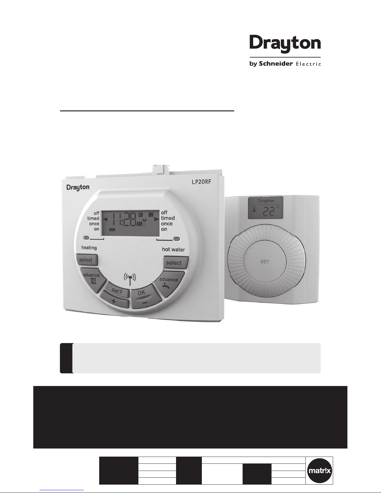
LP20RF & DIGISTAT+RF
Radio frequency controlled room thermostat with dual
channel programmer
Part number RF562DR
Installation & User Guide
For GREENSTAR CDi, GREENSTAR i JUNIOR and GREENSTAR Si MODELS also
GREENSTAR i SYSTEM and GREENSTAR CDi SYSTEM MODEL(only when used with
the optional integral diverter).
!
Spar es Part nu mber 310 03
Spar es Part nu mber 2259 0DR
Support
PLEASE READ THESE IN STRUCTION S
CAREFULLY BEFORE STARTING.
These instructions are applicable to the
Drayton model(s) stated on the front
cover of this manual only and must not
be used with any other make or model.
These instructions apply in the UK only
and should be followed except for any
statutory obligation.
If you are in any doubt contact the
Drayton technical helpline.
This accessory must be tted by a
competent person. Failure to comply
could lead to prosecution.
Leave these instructions with the user
or at the appliance.
!
Abbreviations
CH = Central Heating
DHW = Domestic Hot Water
RF = Radio Frequency
DLS = Daylight Saving
BST = British Summer Time
GMT = Greenwich Mean Time
C = Celsius (Centigrade)
IP = Ingress Protection
V = Volt
m = metre
mA = milliAmpere
Denitions (DLS/BST)
Summe r time begins: L ast Sunda y in March at
1:00 am G MT (Cloc ks are put for ward by 1 hour)
Summer time ends: Las t Sunday in October at
2:00 am B ST (Clocks are p ut back by 1 hour)
Protect your environment
Proper battery recycling
Elect ronic devic es and batte ries, rechar geable or not,
should not be di sposed of int o ordinary househo ld waste.
Inst ead, they mus t be recycled p roperly to p rotect
the env ironment and c ut down the was te of precious
reso urces. Your local w aste management a uthority
can sup ply detail s concerning the prop er disposa l of
batteries.
Symbols
Central Heating
Dome stic Hot Water
Radio Fr equency (R F) Tran smitter
Sales: +4 4(0)845 1305 522
Technical: +4 4(0)845 1307722
customer.care@draytoncontrols.co.uk
www.draytoncontrols.co.uk
@DraytonHeating
/DraytonControls
Inst allation & User Gui de
06515085001 ISSB
Client Drayton File Name 7342 Drayton Am ends LP20RF 0651508 5001 ISSB
Artworker -
Proof Stage
PRINT
Finished Size A5 148x210mm
Creative Director Mike Lane Artwork % 100%
Modification Date 19/03/15 9:2 1AM Bleed 3mm
Table of contents
Technical Data .............................................................................................................................. 2
Installation Guide .......................................................................................................... 3
LP20RF Installation ..................................................................................................... 4
Wireless Commissioning & Signal Strength .................................................................. 5-6
Signal Strength ............................................................................................................ 7
User Guide ....................................................................................................................... 8
Digistat+RF Room Thermostat ................................................................................................... 9
Advanced Features ...................................................................................................... 10-12
Tamper Proong / Fault Diagnosis / Battery Replacement ........................................... 12
LP20RF Programmer & Receiver ............................................................................................... 13
The Standard Program................................................................................................. 14
Changing the Program ................................................................................................ 15-20
Maintenance ................................................................................................................................. 21
1LP20 R F & D IG I STAT+R F
06515085001 ISSB
Digistat+RF Transmitter
Thermostat
LP20RF Receiver
Power supply 2x AA 1.5V a lkaline bat teries 24Vd.c. less th an 65mA
Radio frequency 433 MHz 433 MHz
Radio s ignal range 30m ty pically. The r ange may be af fected by t he composition / den sity and
numbe r of walls bet ween the Digi stat+RF and L P20RF.
Temperature setting range 5°C to 30°C
Control Accuracy + 0. 5°C @ 20°C Bet ter than ±1 se cond per day
@ 25°C
Ambient Temperature (Operating) 0°C to 50°C 0°C to 50°C
Ambient Temperature (Storage) –20°C to 55°C
--
Humidity operating range
--
30 - 95 % non conden sing up to
45°C
Mounting Suitable for surface mounting
Wiring No wiring required
Clas s of protect ion /
Degree of protection
IP30 IP24
Bat tery back up time & date 10 yea rs min. 10 yea rs min.
Shortest switching period 1 minute 1 minute
Energy Class IV = 2% (Acc. EU 81 1/2013, 812 /2013, 813/2 013, 814/201 3)
Pollution Class 2 2
Software Class A A
Ball pressure test 90°C 90°C
Technical Data
Relevant EC Directives:
2006/9 5/EC Low Voltag e Direct ive
2004/108/EC Electromagnetic Compatibility Directive
1999/5/EC R&TTE Direc tive
2006/66/EC Battery Directive
2011 /65/EU Ro HS Directive
Applied Standards:
EN60730 -1; EN60730-2-7; EN60730-2-9
EN 300 2 20-2; EN 3 01 489-3
Pack Contents:
LP20R F Programm er / RF receiv er
Digistat+RF transmitter
Screws (x 2)
Wall Plugs (x 2)
Instructions
Bat teries (x2) A A Alkaline
2 Inst allation & User Gui de
06515085001 ISSB

Client Drayton File Name 7342 Drayton Am ends LP20RF 0651508 5001 ISSB
Artworker -
Proof Stage
PRINT
Finished Size A5 148x210mm
Creative Director Mike Lane Artwork % 100%
Modification Date 19/03/15 9:2 1AM Bleed 3mm
Installation Guide
LP20RF & DIGISTAT+RF
3LP20 R F & D IG I STAT+R F
06515085001 ISSB
NOTE:
This accessory must be tted by a competent person.
Failure t o comply could lead to prose cution.
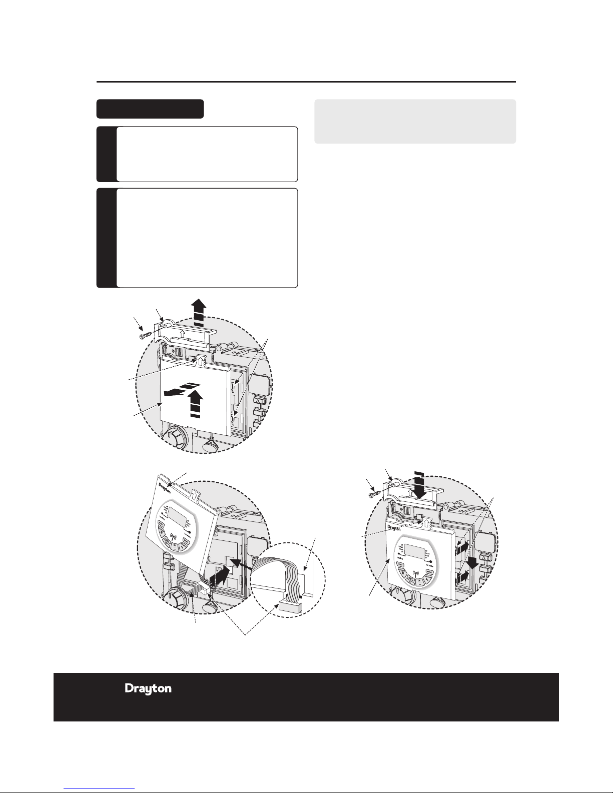
1.
Remove t he boiler out er casing and contro l panel
fascia to gain a ccess to the boiler co ntrol panel .
2.
Releas e the securin g screws.
3.
Pull the cover p anel up to remove.
4.
Grip the tab and pull upwards to dise ngage clips,
pull for ward to remove bl anking plat e or existin g
programmer.
5.
Align th e connecto r plug pins into s ocket on the
PCB an d push fully ho me.
6.
Feed the ribb on cable into th e recess.
7.
Align th e programme r and locate th e clips, push
into th e slots then down to se cure.
8.
Locate the co ver panel in pl ace and secure w ith
the s crew.
9.
Repla ce fascia cove r and outer ca sing before
swit ching on the elec trical sup ply and boiler.
J
Switch boile r on when comple ted.
CAUTION:
Isolate the mains elec tricity supply
before star ting any work and obser ve
all relevant safety precautions.
Obser ve electro-static discharge
precautions: do not touch the pcb
circuit.
!
DANGER:
230 volts do not touch the electrical
components or circuits.
F
Installation Guide LP20RF Programmer & Receiver
Clips
Cover panel
Tab
Blanking
plate
Screw
Clips
Cover panel
Tab
Blanking
plate
Recess
Programmer
Ribbon cable
Connector plug
Screw
Clips
Cover panel
Tab
Blanking
plate
Tab
Cover panel
Clips
Screw
Programmer
Recess
Programmer
Ribbon cable
Connector plug
Screw
LP20RF Installation
4 Install ation & User Gu ide
06515085001 ISSB
Client Drayton File Name 7342 Drayton Am ends LP20RF 0651508 5001 ISSB
Artworker -
Proof Stage
PRINT
Finished Size A5 148x210mm
Creative Director Mike Lane Artwork % 100%
Modification Date 19/03/15 9:2 1AM Bleed 3mm
Installation Guide LP20RF & DIGISTAT+RF
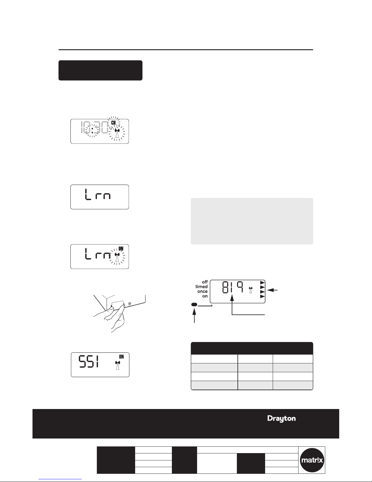
CLOCK?
Befo re fixing t he Digist at+RF to the w all it is reco mmended
to fir st check th e signal str ength fro m that locati on.
To do this, afte r initial st art up, the colo n, C H and antenna
symbols should be ashing on the LP20RF display.
1.
Pres s the set? button 4 time s.
2.
Pres s the OK butt on once.
3.
Pres s the set? button 4 time s; Lr n and OFF shoul d
be displayed.
4.
Pres s the + button so the di splay show s ON and a
ashing antenna symbol. The learn mode is now
ready to receive a si gnal from the t ransmitter
during t he next tw o minutes.
5.
Take the Digis tat+RF unit and stand near t he boiler.
6.
Remove the battery cover and t the batteries.
7.
The symbols on the receiver will stop ashing and
the display w ill show ‘SSI, A ntenna and ON’.
8.
Pres s ‘SET’ on the re ceiver and the displ ay will
show ‘S SI and Antenn a’.
CLOCK?
10:30
OFF
CLOCK?
10:30
OFF
CLOCK?
6:30
10:30
OFF
9.
Afte r a few seconds the dis play will show ‘- - -’.
Remove t he batteries from the Di gistat+RF, pres s
and hold the ‘set’ button whilst retting the
batt eries, keep th e ‘set’ butt on held and aft er a few
secon ds the display will show ‘rF’ whic h indicates
that th e Digistat+R F is continuo usly sending a
signal t o the LP20RF (receiver).
The receive r display wil l now show the ‘lear nt’
trans mitter cod e and the antenn a’ as well as the
signal s trength as indic ated by the che vrons on the
right hand side of the dis play.
J
Place the transmitter in the desired nal position
and ret urn to the boiler to che ck the receiv er
displ ay. The ideal t ransmitt er position w ill result
in the re ceiver disp lay showing 4 ch evrons and the
LED will b e green.
K
If the LE D is red or no LED is s howing and the
displ ay indicate s 1 or 2 chevrons, the tra nsmitter
will ne ed to be re-posi tioned until the LED
change s to amber or gr een and 3 or 4 chev rons are
indicated on the display.
NOTE:
If ther e is no LED and the di splay show s ‘- - -’, th ere
is no signal bei ng received at all fro m the transmi tter.
Transmissi on will resume o nce the trans mitter is reposit ioned in a par t of the house where an a mber or
green LED and 3 or 4 chevr ons are achiev ed.
L
Once yo u are happy tha t, when in the des ired
locat ion, the transmi tter is sen ding a good sig nal
to the re ceiver i.e. amber or green an d 3 or 4
chevrons, the transmitter can be xed to the wall.
CLOCK?
6:30
10:30
OFF
LED Indication Chevrons RF Strength
Green 4 Very strong
Amber 3 Strong
Red 2 Weak
None 1 Ver y wea k
Signal strength
indicators
Transmitter code
(may be different)
LED indicator shows different colour depending
on signal strength (see table below)
Wireless Commissioning
& Signal Strength
5LP20 R F & D IG I STAT+R F
06515085001 ISSB
Installation Guide LP20RF & DIGISTAT+RF
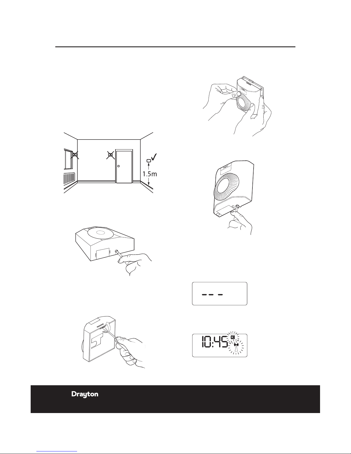
Positioning the Digistat +RF room thermostat
The Dig istat is a radio fre quency devi ce which is very
exible for positioning as there is no need for hard wiring
to the ap pliance. The device s hould be moun ted in an
open ar ea, no closer than 30cm fr om metal obj ects,
including wall boxes.
Mount t he Digista t+RF on a wall which is not su bject to
direc t sunlight or dr aughts, pre ferably on an in side wall,
1.5 metres above the oor. The Digistat+RF must also not
be directly inuenced by radiators or other appliances
givin g off heat.
Mounting the Digistat +RF room thermostat
1.
Loosen the single scr ew from the bo ttom of the
transmitter using a small at bladed screwdriver.
2.
Caref ully inser t the screwdr iver into the s lot
locat ed at the back of th e digistat n ear the top and
very g ently lever up wards a frac tion to relea se
the tab secur ing the front of t he transmit ter to the
back cov er. The back cove r can now be secured to
the wal l.
3.
Repla ce the front by l ocating in positio n and
pushing fully onto th e back cover unt il the tab
engag es at the top of th e transmit ter.
4.
Retighten th e screw at the botto m of the unit to
fully s ecure the front to the b ack cover.
To cancel signal strength mode:
1.
Remove the batteries from the Digistat+RF
trans mitter to cancel the cons tant trans mission.
2.
Afte r a few seconds the receive r display wil l show
‘---’ .
3.
Pres s ‘OK’ on the LP20RF rec eiver and the displ ay
will re turn to the time with th e ‘CH and Antenna’
ashing.
4.
Re-insert th e batterie s into the tran smitter and the
RF link will be re-est ablished.
6 Inst allation & User Gui de
06515085001 ISSB
 Loading...