

Page 1
Client Drayton File Name 7542 Dra yto n LP 10RF & D IG IS TAT+2RF 0651508 60 01 ISS C
Artworker -
Proof Stage
PRINT
Finished Size A5 148x210mm
Creative Director Mike Lane Artwork % 100%
Modification Date 21/08/15 2:56PM Bleed 3mm
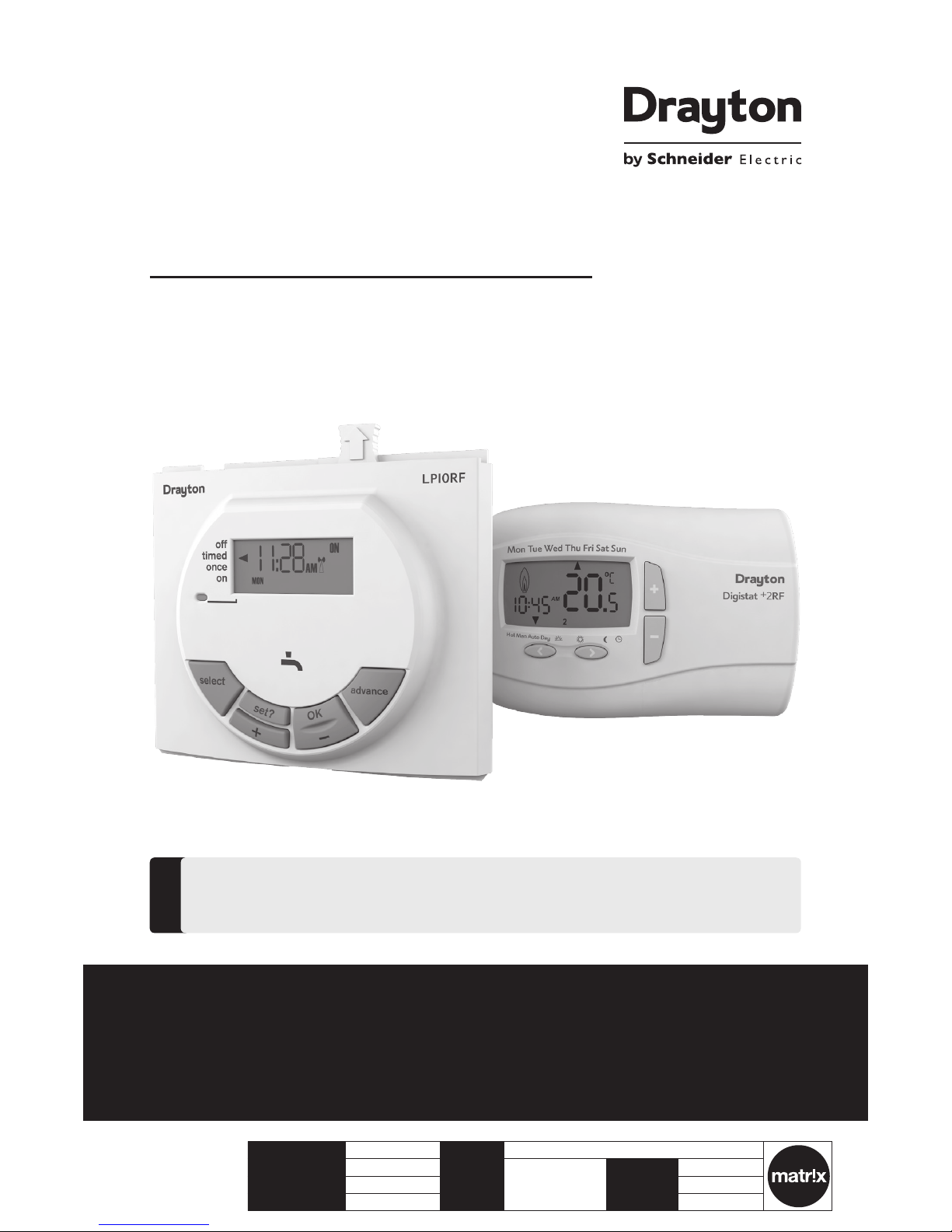
LP10RF & DIGISTAT+2RF
Radio frequency controlled programmable room
thermostat with domestic hot water programmer
Part number RF560DR
Installation & User Guide
For GREENSTAR CDi, GREENSTAR i JUNIOR and GREENSTAR Si MODELS also
GREENSTAR i SYSTEM and GREENSTAR CDi SYSTEM MODEL(only when used with
the optional integral diverter).
!
Spar es Part nu mber 2209 0
Spar es Part nu mber 225 89DR
Page 2
Support
PLEASE READ THES E INSTRUCTION S
CAREFULLY BEFORE STARTING.
These instructions are applicable to the
Drayton model(s) stated on the front
cover of this manual only and must not
be used with any other make or model.
These instructions apply in the UK only
and should be followed except for any
statutory obligation.
If you are in any doubt contact the
Drayton technical helpline.
This accessory must be tted by a
competent person. Failure to comply
could lead to prosecution.
Leave these instructions with the user
or at the appliance.
!
Abbreviations
CH = Central Heating
DHW = Domestic Hot Water
RF = Radio Frequency
DLS = Daylight Saving
BST = British Summer Time
GMT = Greenwich Mean Time
C = Celsius (Centigrade)
IP = Ingress Protection
V = Volt
m = metre
mA = milliAmpere
Denitions (DLS/BST)
Summe r time begins: L ast Sunda y in March at
1:00 am G MT (Clocks a re put forw ard by 1 hour)
Summer time ends: Last Sunday in October at
2:00 am B ST (Clocks are p ut back by 1 hour)
Protect your environment
Proper battery recycling
Elect ronic devic es and batte ries, rechar geable or not,
should not be dispos ed of into ordinary hou sehold was te.
Inst ead, they mus t be recycled p roperly to p rotect
the env ironment and c ut down the was te of precious
reso urces. Your local w aste management a uthority
can sup ply detail s concerning the prop er disposa l of
batteries.
Symbols
Dome stic Hot Water
Radio Fr equency (R F) Transmi tter
Sales: +4 4(0)845 1305 522
Technical: +44(0)845 1307722
customer.care@draytoncontrols.co.uk
www.draytoncontrols.co.uk
@DraytonHeating
/DraytonControls
Inst allation & User Gui de
06515086001 ISSC
Page 3
Client Drayton File Name 7542 Dra yto n LP 10RF & D IG IS TAT+2RF 0651508 60 01 ISS C
Artworker -
Proof Stage
PRINT
Finished Size A5 148x210mm
Creative Director Mike Lane Artwork % 100%
Modification Date 21/08/15 2:56PM Bleed 3mm
Table of contents
Technical Data .............................................................................................................................. 2
Installation Guide .......................................................................................................... 3
LP10RF Installation ...................................................................................................... 4
Wireless Commissioning & Signal Strength .................................................................. 5-6
Signal Strength ............................................................................................................7
Installer Options .......................................................................................................... 8-9
User Guide .......................................................................................................................10
DIGISTAT+2RF Room Thermostat ............................................................................................. 11
Controls and Display Layout ......................................................................................12
Basic Settings .............................................................................................................. 13-15
User Options ............................................................................................................... 15-19
Battery Change ........................................................................................................... 19
LP10RF Programmer & Receiver ................................................................................................ 20
The Standard Program ................................................................................................21
Changing the Program ................................................................................................ 22-25
Maintenance ................................................................................................................................. 25
1LP 10 RF & D IG IS TAT+2 RF
06515086001 ISSC
Page 4
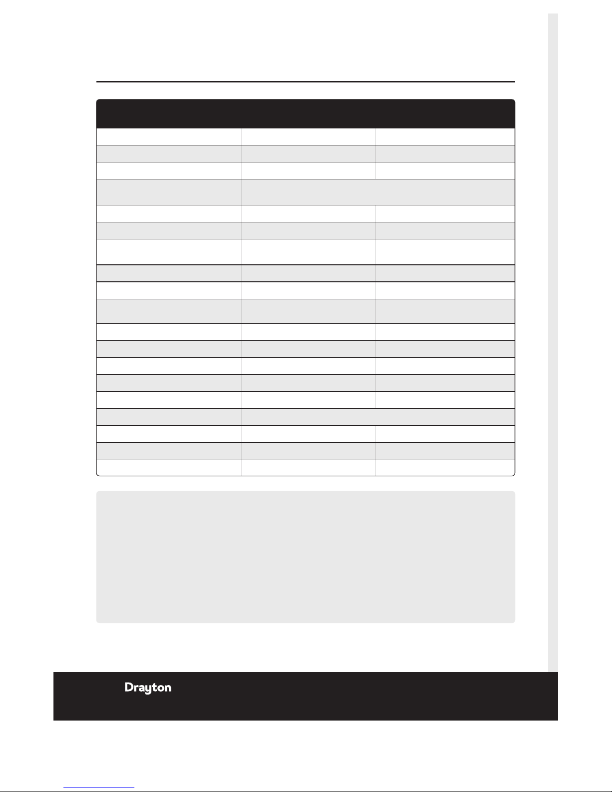
Digistat +2RF Transmitter
Thermostat
LP10RF Receiver
Dimensions 137mm x 96. 5mm x 31.3mm --
Power supply 2x AA 1.5V a lkaline bat teries 24Vd.c. less th an 65mA
Radio frequency 433 MHz 433 MHz
Radio s ignal range 30m ty pically. The r ange may be af fected by t he composition / den sity and
numbe r of walls bet ween the Digi stat+2RF and LP1 0RF.
Temperature range 5°C to 32°C --
Ambient operating temperature 0°C to +4 0°C 0°C to +50°C
Humidity operating range 25 - 90% non conde nsing up to
45°C
30 - 95% non conden sing up to 45°C
Clas s of operation -- II
Degrees of protection IP30 IP24
Control Accuracy +0.5°C @ 20°C Bet ter than ±1 se cond per day @
25°C
Bat tery life (with alk aline batt eries) approx. 2 years N/A
Bat tery back up time and date 10 yea rs min. 10 yea rs min.
Shortest switching period 1 minute 1 minute
Hot water pre-heat setti ngs -- 3 ON / 3 OFF
Central heating settings 6 per day --
Energy Class IV = 2% (Acc. EU 811/ 2013, 812/2013, 81 3/2013, 814/20 13)
Pollution Class 2 2
Software Class A A
Ball pressure test 90°C 90°C
Technical Data
Relevant EC Directives:
2006/9 5/EC Low Voltag e Direct ive
2004/108/EC Electromagnetic Compatibility Directive
1999/5/EC R&TTE Direc tive
2006/66/EC Battery Directive
2011 /6 5/EU RoHS Dire ctive
Applied Standards:
EN60730 -1; EN60730-2-7; EN60730-2-9
EN 300 2 20-2; EN 301 4 89-3
Pack Contents:
LP10 RF Progra mmer / RF receiver
Digistat+2RF transmitter
Screws (x 2)
Wall Plugs (x 2)
Instructions
Bat teries (x2) A A Alkaline
2 Inst allation & User Gui de
06515086001 ISSC
Page 5

Client Drayton File Name 7542 Dra yto n LP 10RF & D IG IS TAT+2RF 0651508 60 01 ISS C
Artworker -
Proof Stage
PRINT
Finished Size A5 148x210mm
Creative Director Mike Lane Artwork % 100%
Modification Date 21/08/15 2:56PM Bleed 3mm
Installation Guide
LP10RF & DIGISTAT+2RF
3LP 10 RF & D IG IS TAT+2 RF
06515086001 ISSC
Page 6
NOTE:
This accessory must be tted by a competent person.
Failure t o comply could lead to pr osecution.
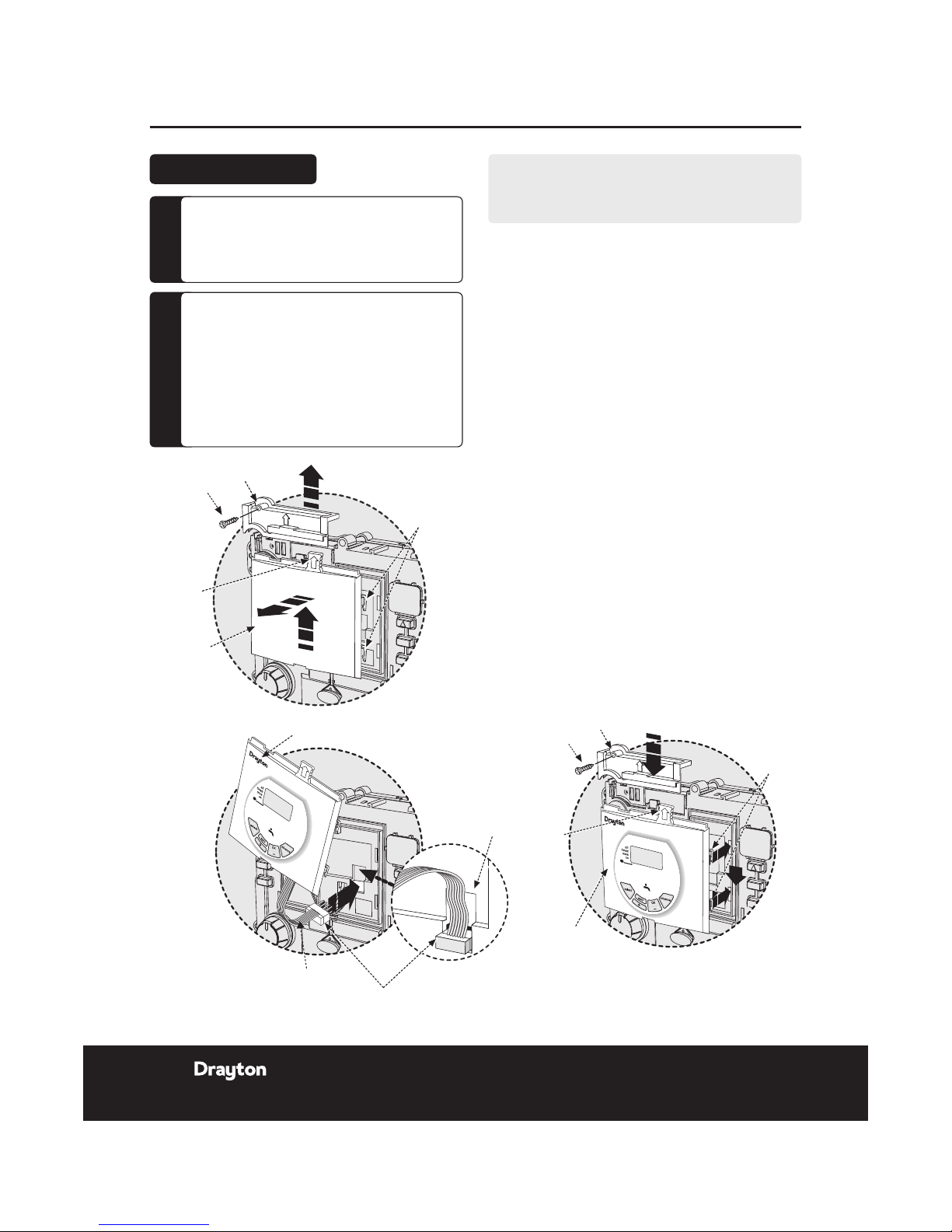
1.
Remove t he boiler out er casing and contro l panel
fascia to gain access to the boiler control p anel.
2.
Releas e the securin g screws.
3.
Pull the cover p anel up to remove.
4.
Grip the tab and p ull upwards t o disengage clips,
pull for ward to remove bl anking plat e or existin g
programmer.
5.
Align th e connecto r plug pins into s ocket on the
PCB an d push fully ho me.
6.
Feed the ribb on cable into th e recess.
7.
Align th e programme r and locate th e clips, push
into th e slots then down to se cure.
8.
Locate the cover pan el in place and s ecure with
the s crew.
9.
Repla ce fascia cove r and outer ca sing before
swit ching on the elec trical sup ply and boiler.
J
Switch boile r on when comple ted.
CAUTION:
Isolate the mains electricity supply
before star ting any work and observe
all relevant safety precautions.
Obser ve electro-static discharge
precautions: do not touch the pcb
circuit.
!
DANGER:
230 volts do not touch the electrical
components or circuits.
F
Installation Guide LP10RF Programmer & Receiver
Clips
Cover panel
Tab
Blanking
plate
Screw
Clips
Cover panel
Tab
Blanking
plate
Recess
Programmer
Ribbon cable
Connector plug
Screw
Clips
Cover panel
Tab
Blanking
plate
Tab
Cover panel
Clips
Screw
Programmer
Recess
Programmer
Ribbon cable
Connector plug
Screw
LP10RF Installation
4 Install ation & User Gu ide
06515086001 ISSC
Page 7
Client Drayton File Name 7542 Dra yto n LP 10RF & D IG IS TAT+2RF 0651508 60 01 ISS C
Artworker -
Proof Stage
PRINT
Finished Size A5 148x210mm
Creative Director Mike Lane Artwork % 100%
Modification Date 21/08/15 2:56PM Bleed 3mm
Installation Guide LP10RF & DIGISTAT+2RF
CLOCK?
Befo re fixing t he DIGIS TAT+2RF to the wal l it is
recom mended to f irst che ck the signal s trength f rom that
location.
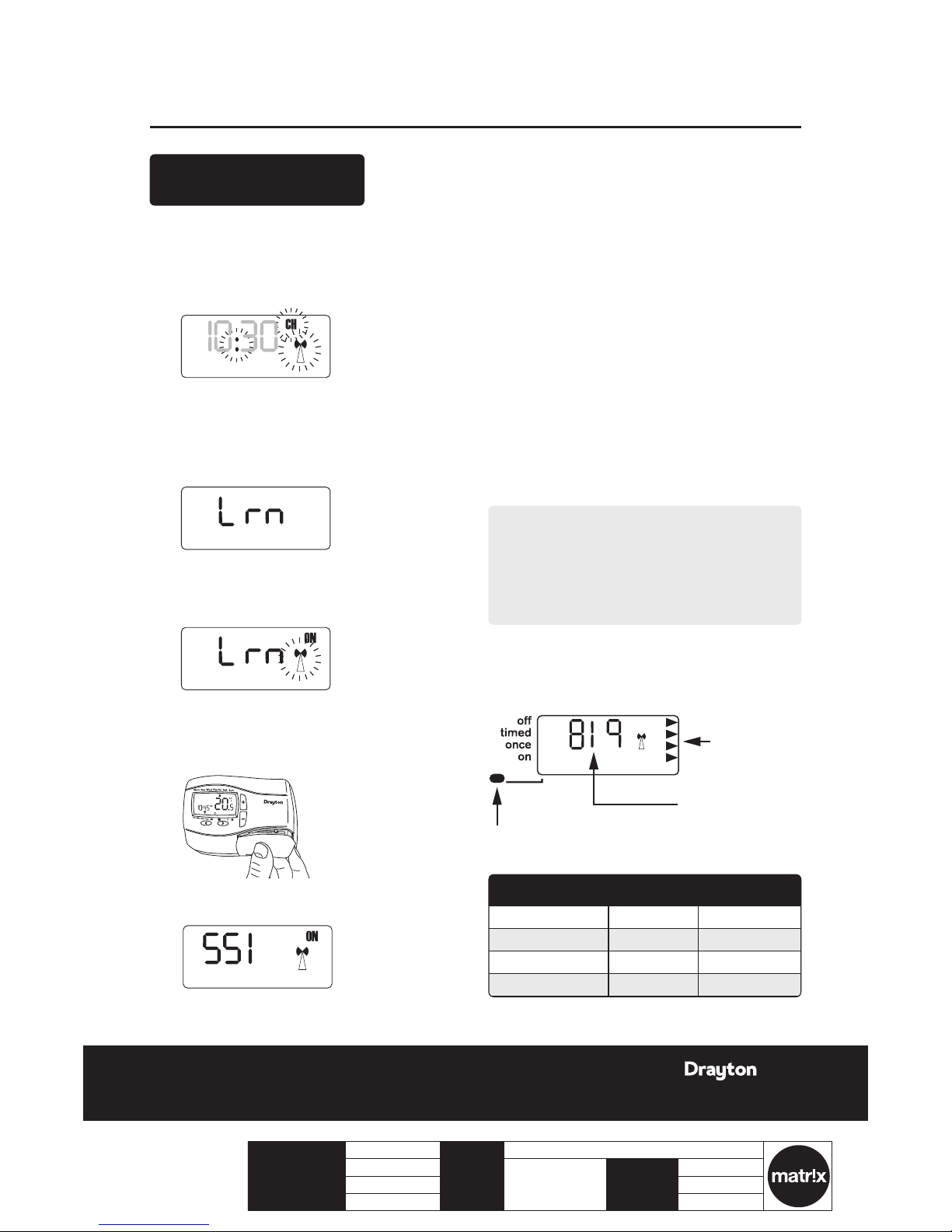
To do this, afte r initial st art up, the colo n, CH and a ntenna
symbols should be ashing on the LP10RF display.
1.
Pres s the set? button 4 time s.
2.
Pres s the OK butt on once.
3.
Pres s the set? button 4 time s; Lrn and O FF should
be displayed.
4.
Pres s the + button so the di splay shows ON and a
ashing antenna symbol. The learn mode is now
ready to receive a si gnal from the transmi tter
during t he next tw o minutes.
5.
Take the Digis tat+2RF uni t and stand ne ar the
boile r.
6.
Remove the battery cover and t the batteries.
7.
The symbols on the receiver will stop ashing and
the display w ill show ‘SSI, A ntenna and ON’.
8.
Pres s ‘SET’ on the re ceiver and the displ ay will
show ‘S SI and Antenn a’.
CLOCK?
10:30
OFF
CLOCK?
10:30
OFF
9.
Afte r a few seconds the display w ill show ‘- - -’.
Remove the batteries from the Digistat+2RF,
press and hold the ‘+’ button whilst retting the
batt eries, keep th e ‘+’ button held and aft er a few
secon ds the display will sh ow ‘rF’ which indicates
that th e DIGISTAT+2RF is continuou sly sending a
signal t o the LP10R F (recei ver).
The receive r display will now show the ‘lear nt’
trans mitter cod e and the antenn a’ as well as the
signal s trength as indicated b y the chevron s on the
right hand side of the dis play.
J
Place the transmitter in the desired nal position
and ret urn to the boiler to che ck the receiv er
displ ay. The ideal t ransmitt er position w ill result
in the re ceiver disp lay showing 4 ch evrons and the
LED will b e green.
K
If the LE D is red or no LED is s howing and the
displ ay indicate s 1 or 2 chevrons, the tra nsmitter
will ne ed to be re-posi tioned until the LED
change s to amber or gr een and 3 or 4 chev rons are
indicated on the display.
NOTE:
If ther e is no LED and the di splay show s ‘- - -’, there
is no signal being rece ived at all fro m the transmitter.
Transmissi on will resume o nce the trans mitter is reposit ioned in a par t of the house where an a mber or
green LED and 3 or 4 chevr ons are achiev ed.
L
Once yo u are happy tha t, when in the des ired
locat ion, the transmi tter is sen ding a good sig nal
to the re ceiver i.e. amber or gr een and 3 or 4
chevrons, the transmitter can be xed to the wall.
CLOCK?
6:30
10:30
OFF
LED Indication Chevrons RF Strength
Green 4 Very strong
Amber 3 Strong
Red 2 Weak
None 1 Ver y wea k
Signal strength
indicators
Transmitter code
(may be different)
LED indicator shows different colour depending
on signal strength (see table below)
Wireless Commissioning
& Signal Strength
5LP 10 RF & D IG IS TAT+2 RF
06515086001 ISSC
Page 8
Installation Guide LP10RF & DIGISTAT+2RF
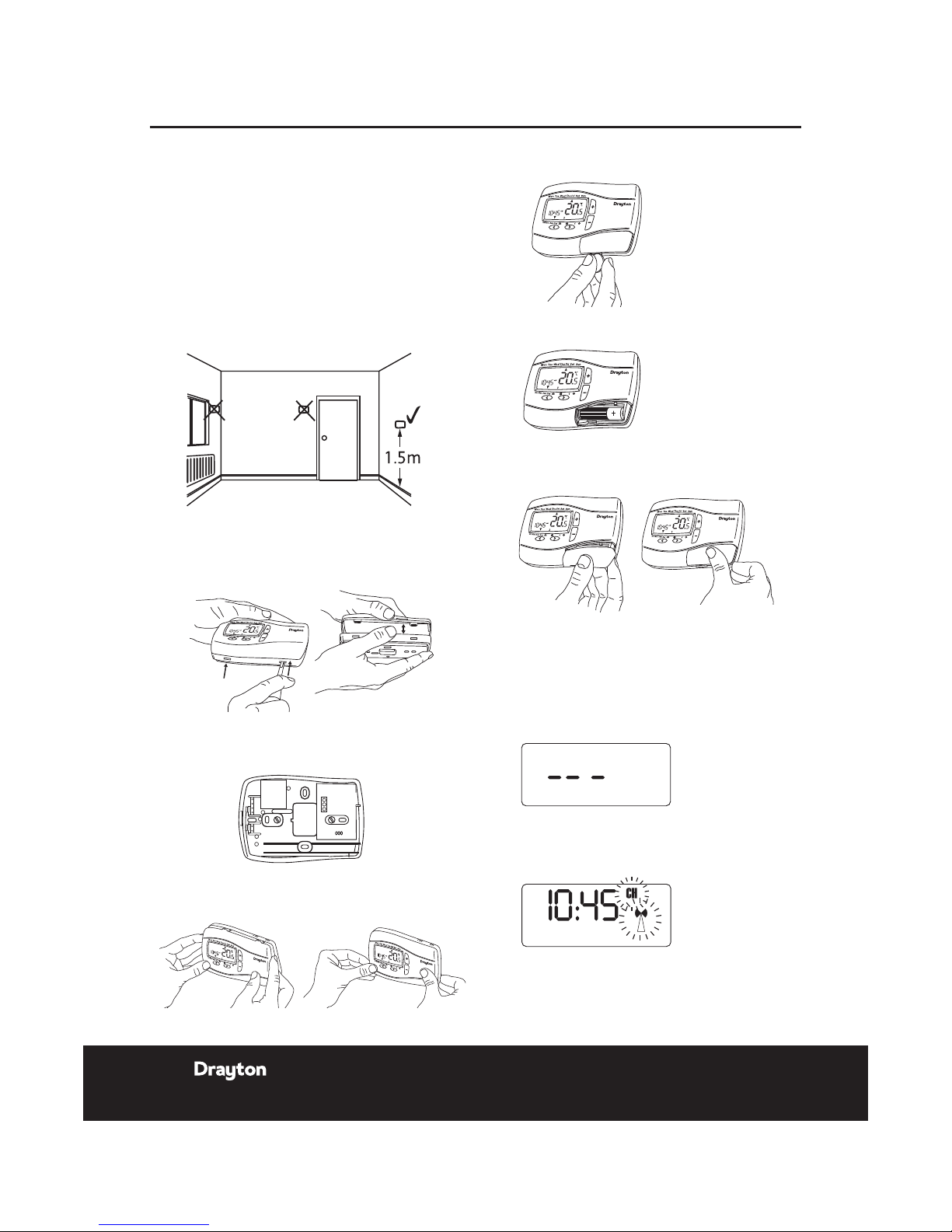
Positioning the Digistat +2RF room thermostat
The Dig istat is a radio fre quency devi ce which is very
exible for positioning as there is no need for hard wiring
to the ap pliance. The device s hould be mounted in an
open ar ea, no closer than 30cm fr om metal obj ects,
including wall boxes.
Mount t he Digista t+2R F on a wall which is not subj ect
to dire ct sunlight or draughts, pr eferably on an inside
wall, 1.5 metres above the oor. The Digistat+2RF must
also not be directly inuenced by radiators or other
applia nces giving o ff heat.
Mounting the Digistat +RF room thermostat
1.
Remove the front cover using a at screwdriver and
separ ate from back p late.
2.
Fix the b ack plate dir ectly onto t he wall using th e
allocated xing points and suitable wall plugs and
screws.
3.
Repla ce the front cover by lo cating in posi tion and
pushing fully o nto the back cover.
Digistat +2RF
D
i
g
i
s
t
a
t
+
2
R
F
Digistat +2RF
D
i
g
i
s
t
a
t
+
2
R
F
D
i
g
i
s
t
a
t
+
2
R
F
Digistat +2RF
D
i
g
i
s
t
a
t
+
2
R
F
D
i
g
i
s
t
a
t
+
2
R
F
Digistat +2RF
4.
Remove t he batter y cover using a coin
5.
Inst all the 2 AA ba tteries provid ed
6.
Replace battery cover
To cancel signal strength mode:
1.
Remove the batteries from the Digistat+2RF
trans mitter to cancel the cons tant trans mission.
2.
Afte r a few seconds the receive r display will show
‘---’ .
3.
Pres s ‘OK’ on the LP10 RF receiv er and the display
will re turn to the time with th e ‘CH and Antenna’
ashing.
4.
Re-insert the batt eries into th e transmit ter and the
RF link will be re-est ablished.
6 Inst allation & User Gui de
06515086001 ISSC
Page 9
Client Drayton File Name 7542 Dra yto n LP 10RF & D IG IS TAT+2RF 0651508 60 01 ISS C
Artworker -
Proof Stage
PRINT
Finished Size A5 148x210mm
Creative Director Mike Lane Artwork % 100%
Modification Date 21/08/15 2:56PM Bleed 3mm
Installation Guide LP10RF & DIGISTAT+2RF
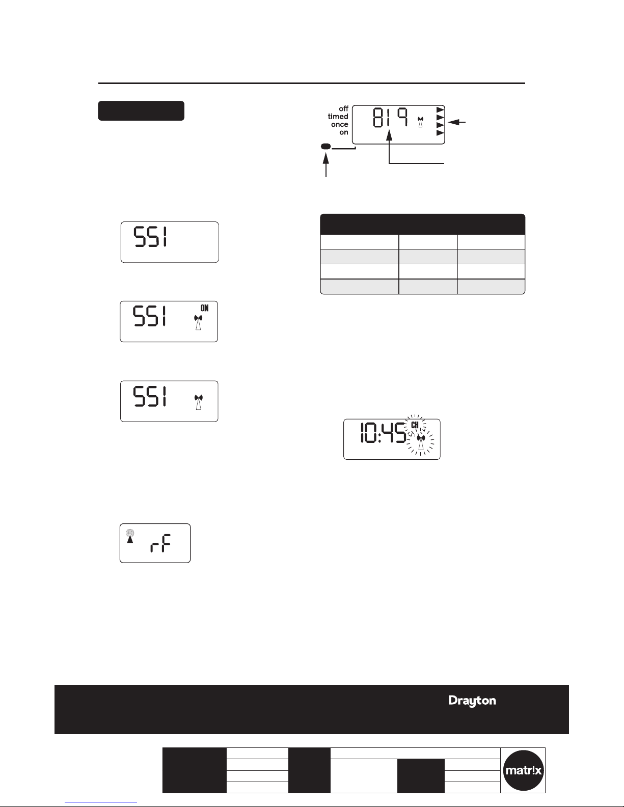
Signal Strength
To check signal strength on previously
installed and paired units:
1.
Pres s the ‘set’ but ton 4 times on th e LP10RF.
2.
Pres s ‘OK’ once.
3.
Pres s the ‘set’ but ton 5 times. The disp lay will show
‘SSI and OFF’.
4.
Pres s the ‘+’ butt on so that the di splay shows ‘SSI,
Antenna and ON’.
5.
Pres s the ‘set’ but ton so the disp lay shows ‘S SI and
Antenna’.
6.
Afte r a few seconds the display w ill show ‘---’.
7.
Remove the batteries from the Digistat+2RF
trans mitter and w ait until the dis play has fad ed
away.
8.
Pres s and hold the ‘+’ butt on on the trans mitter
while re-inser ting the bat teries and ke ep the button
depresse d until the disp lay shows ‘rF’ .
OFF
OFF
OFF
6:30
OFF
LED Indication Chevrons RF Strength
Green 4 Very strong
Amber 3 Strong
Red 2 Weak
None 1 Ver y wea k
To cancel signal strength mode:
1.
Remove t he batteries fro m the transmi tter to
cancel the constant transmission.
2.
Afte r a few seconds the receive r display will show
‘---’ .
3.
Pres s ‘OK’ on the receiver di splay and the d isplay
will re turn to the time with th e ‘CH and Antenna’
ashing.
4.
Re-insert the batt eries into th e transmit ter and the
RF link will be re-est ablished.
Signal strength
indicators
Transmitter code
(may be different)
LED indicator shows different colour depending
on signal strength (see table below)
Signal strength indicators
Signal Strength
7LP 10 RF & D IG IS TAT+2 RF
06515086001 ISSC
Page 10

Installation Guide DIGISTAT+2RF
Option 02 - Freeze Protection
Freeze p rotectio n will switch o n the heating if t he room
tempe rature fall s to 5°C and will then control the
tempe rature at 7°C even if the Digi stat is in OF F mode.
The Fre eze Protect ion default is O N.
To switch off t he Freeze Prot ection mod e enter the
Installer Options Menu (Refer to Installer Options 02)
and chan ge to OFF. Press to accept.
Option 04 & 05 - Low and High Limit
set points.
The use r temperat ure set point s defaults are High 32°C
and Low 5°C , to change these limit s enter the In staller
Optio ns Menu (Refer t o Installe r Options 04 & 0 5).
Option 06 - Intelligent Delayed Start
(Energy saving feature).
The Int elligent De layed Sta rt is an ener gy saving fea ture
which au tomatically redu ces the warm up t ime for the
heating system.
If you wish to change an y of the Insta ller Options a s
shown in the table below, enter th e Installe r Option
Menu fr om Auto mode b y pressing: a nd +
simultaneously for 5 seconds.
Pressing and + again for 5 seconds will exit the
Menu an d return to Aut o mode.
Once th e Installe r Options scr een has been s elected,
th
e
and buttons allow you to scroll
throu gh the Menu (show n below). The + and - allow you
to chan ge values.
Once a v alue has been ch anged pressing before
exiting the Menu will save the new setting. (The below
displ ay shows Option 02 OFF ).
Installer Options
Installer
Options
Function Select
Option
Default
02 Freeze
protection
On Off On
04 Low Set
Point °C
5 High
Limit
5
05 High Set
Point °C
Low
Limit
32 32
06 Delayed
Start
(Energy
saving
feature)
On Off Off
10 Valve
protection
On Off Off
11 Valve
protection
time (Mins)
1 53
12 Application
type
01 0
13 System
Capability
01 0
(* small 1 in lower half of screen
shows which time period is being set
e.g. 1=1st period, 2 = 2nd period etc)
o
r
(* small 1 in lower half of screen
shows which time period is being set
e.g. 1=1st period, 2 = 2nd period etc)
(* small 1 in lower half of screen
shows which time period is being set
e.g. 1=1st period, 2 = 2nd period etc)
(* small 1 in lower half of screen
shows which time period is being set
e.g. 1=1st period, 2 = 2nd period etc)
(* small 1 in lower half of screen
shows which time period is being set
e.g. 1=1st period, 2 = 2nd period etc)
(* small 1 in lower half of screen
shows which time period is being set
e.g. 1=1st period, 2 = 2nd period etc)
8 Inst allation & User Gui de
06515086001 ISSC
Page 11

Client Drayton File Name 7542 Dra yto n LP 10RF & D IG IS TAT+2RF 0651508 60 01 ISS C
Artworker -
Proof Stage
PRINT
Finished Size A5 148x210mm
Creative Director Mike Lane Artwork % 100%
Modification Date 21/08/15 2:56PM Bleed 3mm
Installation Guide DIGISTAT+2RF
If enab led, the star t time should b e set an hour ear lier
than the time yo u want the prop erty to re ach the set
temperature.
Intelligen t Start wil l delay that s tart time, by an amoun t
that it h as calculate d based on the a ctual and se t
temperature.
As the w eather beco mes milder, the star t time is del ayed,
so that f uel is not was ted bringing the roo m up to
temperature earlier than nece ssary.
The Dig istat calculate s approximat ely 10 minut es to raise
the tem perature b y 1°C, up to a maxim um of 6°C.
NOTE:
Intelligen t Delayed S tart only applie s in Auto mode.
Intelligen t Delayed S tart default is in OFF mode.
To switch ON In telligent D elayed St art enter t he
Installer Options Menu (see Installer Options 06).
NOTE:
The Int elligent De layed st art option is not sui table for
under oor application. Ensure Installer option 06 is
set to OFF before nal commissioning for underoor
application.
SPECIAL NOTE:
If the I ntelligen t delayed start f eature is en abled, (Off
chang ed to On in Ins taller opti on 06), please i nform
the end u ser of this fe ature.
The fol lowing special not e has been add ed to the user
instruction to explain the adjustment requirement:
When th e delay peri od is operating indicate d by the
ame symbol ashing, pressing any button returns the
Digis tat to auto mode allo wing normal button operation
until th e next time/ tempe rature event, when i t will
resum e the delay s tart mode o r follows the H oliday,
Manua l, Over ride or Off m odes as sele cted.
Chang es to the inst aller option s and pre-set progr ammes
must be made with the ame symbol not ashing.
Option 10 - Valve Protection
In some h eating sys tems there may be a re quirement to
prote ct the sys tem by opera ting it once a day, for a give n
period.
If valve p rotectio n is selecte d the syste m will be opera ted
for a per iod as shown in v alve protection tim e (m ins).
Valve protecti on time is ever y day at 10.00a m. Valve
prote ction defa ult is OFF.
To enable the valve prot ection mod e enter the Ins taller
Options Menu (Refer to Installer Option 10).
Option 11 - Valve Protection time (mins).
Valve protecti on time can be se t between 1 a nd 5 minutes
(default 3 min utes).
To change this on ce a day on time ent er the Inst aller
Options Menu (Refer to Installer Option 11).
Option 12 - Application Type
Digis tat+2RF can be us ed for differ ent applica tions.
In the in staller menu, selec t:
00 = Gas B oiler
0 1 = Oil Boiler
Option 13- System Capability
Adjus t this setti ng to suit the heating syste m capabilit y.
In the in staller menu, selec t:
00 = Fas t – the house usu ally reache s setpoint in ‹ 1 hour
0 1 = Slow – the house usually reac hes setpoin t in › 1 hour
Display Error code E1
When th e display sho ws an error code (E1) this indicate s
a sensor fault and the he ating syst em will remain O ff.
Pleas e contact your loc al heating ser vice engineer to
repl ace your Digi stat +2RF.
9LP 10 RF & D IG IS TAT+2 RF
06515086001 ISSC
Page 12

User Guide
LP10RF & DIGISTAT+2RF
10 Inst allation & User Gui de
06515086001 ISSC
Page 13

Client Drayton File Name 7542 Dra yto n LP 10RF & D IG IS TAT+2RF 0651508 60 01 ISS C
Artworker -
Proof Stage
PRINT
Finished Size A5 148x210mm
Creative Director Mike Lane Artwork % 100%
Modification Date 21/08/15 2:56PM Bleed 3mm
User Guide DIGISTAT+2RF Room Thermostat
DIGISTAT+2RF Room Thermostat
What is a programmable room thermostat?
...an explanation for householders
A programmab le room therm ostat is bo th a programm er
and a roo m thermost at. A progr ammer allows you to se t
‘On’ and ‘O ff’ time per iods to suit yo ur own lifest yle.
A room th ermosta t works by se nsing the air
tempe rature, switching o n the heating wh en the air
tempe rature fall s below the the rmostat s etting, and
swit ching it off onc e this set temp erature has been
reached.
So, a prog rammable room ther mostat let s you choose
what tim es you want th e heating to be o n, and what
tempe rature it should re ach while it is on. I t will allow
you to s elect diff erent temperatu res in your hom e at
different t imes of the day (and da ys of the week) to m eet
your pa rticular n eeds.
Turning a programmab le room therm ostat to a hig her
set ting will not make t he room heat up a ny faster. How
quickl y the room heats up de pends on the design of
the hea ting syste m, for exa mple, the size of boil er and
radiators.
Neither does the setti ng affect ho w quickly the ro om
cools down. Turning a progr ammable room t hermostat
to a lower s etting wil l result in the ro om being controlle d
at a lower t emperatur e, and saves ene rgy.
The way t o set and use yo ur programm able room
thermostat is to nd the lowest temperature settings
that yo u are comfortable w ith at the dif ferent times you
have cho sen, and then leav e it alone to do it s job. The
best way to do this is to set low temperatures rst, say
18°C, and then tu rn them up by one d egree each day until
you are c omfortable wit h the tempera tures. You won’t
have to adjust t he thermos tat furth er. A ny adjustme nts
above t hese sett ings will was te energy and cost y ou more
money.
If your h eating sys tem is a boiler with rad iators,
there w ill usually be only one programmab le room
therm ostat to con trol the whole hous e. But you can
have dif ferent tem perature s in individua l rooms by
installing thermostatic radiator valves (TRVs) on
indiv idual radiat ors. If you d on’t have TRVs, you should
choos e a temperature that is reasonab le for the whole
house. If you d o have TRVs, you can cho ose a slightl y
higher setting to make sure t hat even the coldest room
is comfo rtable, the n prevent any o verheating i n other
rooms by adju sting the TRVs.
The time on the pr ogrammer mu st be correc t. Some
type s have to be adjusted i n spring and aut umn at the
change s between Gree nwich Mean Time a nd British
Summer Time.
You may be able t o temporarily adjust the h eating
programme, for examp le, ‘Override’, ‘Advance’ or
‘Boo st’. These a re explaine d in the manufactur er’s
instructions.
Programmable room thermostats need a free ow of air
to sense the te mperature, so they m ust not be cove red
by cur tains or bloc ked by furniture. Ne arby elect ric
res, televisions, wall or table lamps may prevent the
thermostat from working properly.
Your Digistat +2RF
The Dig istat +2RF thermost at is a progra mmable
therm ostat 24-H our produc t (the same p rogram for
every day of the week) wh ich allows you t o set up to 6
time and temperature events per day.
Clock Setting
Your Digistat +2RF is tted with a real-time clock, which
is pre-s et at the fact ory. You will not have t o alter the
time se ttings. A sp ecial featur e of this real-time cloc k is
to auto matically up date the time d uring the summer/
winte r time change re moving the ne ed to manually a lter
the clock.
General Operation
With th e unit in Auto mode (the smal l arrow to bot tom
of scre en will point to A uto) the temperature c an be
change d for a short t ime by using the + o r - buttons .
Changi ng the temper ature in this w ay will keep the
Digis tat +2RF set to yo ur new temper ature until th e next
pre-pr ogrammed ev ent (at which time it wi ll revert t o
programmed temperature). The temperature you are
setting will ash on the screen. Once temperature is set,
the unit w ill revert to show ing the curren t temperature.
The indi cator will sh ow on the scree n if the heating i s
turned on.
A ashing ame indicates the product is in intelligent
delayed start mode.
(* small 1 in lower half of screen
shows which time period is being set
e.g. 1=1st period, 2 = 2nd period etc)
(Fig 3)
How to replace the batteries see fig 3.
Remove the battery cover using a coin. Replace the spent
batteries with 2 x 1.5V IEC LR6 (AA) Alkaline batteries ensuring
correct orientation. Replace the battery cover pressing fully home.
2. Once the time has been set
press to confirm and
use the + or – button to
adjust required temperature
(temperature shown flashing)
3. Once the temperature has
been set press to
confirm and move to the next
time and temperature periods
to be adjusted confirming
changes by pressing
button. (max 6 periods).
4. To exit press or
until you return to auto
mode with the bottom arrow
Drayto n
Digist at +2RF
Digist at +2RF
Digist at +2RF
Digist at +2RF
Drayto n
Drayto n
Drayto n
(* small 1 in lower half of screen
shows which time period is being set
e.g. 1=1st period, 2 = 2nd period etc)
How to replace the batteries see fig 3.
Remove the battery cover using a coin. Replace the spent
batteries with 2 x 1.5V IEC LR6 (AA) Alkaline batteries ensuring
correct orientation. Replace the battery cover pressing fully home.
2. Once the time has been set
press to confirm and
use the + or – button to
adjust required temperature
(temperature shown flashing)
3. Once the temperature has
been set press to
confirm and move to the next
time and temperature periods
to be adjusted confirming
changes by pressing
button. (max 6 periods).
Drayto n
Digist at +2RF
Digist at +2RF
Digist at +2RF
Digist at +2RF
Drayto n
Drayto n
Drayto n
11LP1 0R F & D IG IS TAT+2 RF
06515086001 ISSC
Page 14

Controls and Display Layout
Drayton
Digistat
+2
RF
+ or - buttons
for setting
adjustments
Clock
mode
RH (right hand)
button, moves the
pointer to the right,
selects and accepts
changes
Time/Temperature
Program events 1 to 6
in sequence, morning,
midday and night
LH (left hand) button,
moves the pointer to
the left for selection
Holiday,
Manual, Auto,
Day, Program
Pointer
(mode
indicator)
Time
Flame shows when
calling for heat
Pointer (day)
Days
Temperature
NOTE:
Temperature displayed is actual room temperature
unles s adjusting the + or - button w hen it displ ays
the set tempe rature. Onc e adjustment is comp lete
and af ter 5 seconds this wil l return to ac tual room
temperature.
User Guide DIGISTAT+2RF Room Thermostat
12 Inst allation & User Gui de
06515086001 ISSC
Page 15

Client Drayton File Name 7542 Dra yto n LP 10RF & D IG IS TAT+2RF 0651508 60 01 ISS C
Artworker -
Proof Stage
PRINT
Finished Size A5 148x210mm
Creative Director Mike Lane Artwork % 100%
Modification Date 21/08/15 2:56PM Bleed 3mm
Basic Settings
The Dig istat +2RF thermost at is a progra mmable
therm ostat 24-H our (the same pro gram for ever y day of
the wee k) and allows you t o set 6 time and te mperature
events per day.
Digistat +2RF Pre-set Program
Your Digist at +2RF com es with the following d efault
set tings pre-pro grammed for y our convenie nce:
Pre-set Program 1 (9 til 5)
As you can see, at 06:30 , th e heating will come on
to rais e the temper ature to 20º C. At 08:30, the
tempe rature set p oint is dropp ed from 20º C down
to 16º C, it stays at 16ºC throug hout the day, un til
16:30 wh en the tempe rature incre ases to 21ºC. T he
tempe rature then drops d own to a night-setb ack
tempe rature of 7º C until 06:30 wh en the cycle rep eats
for the next d ay.
Event 1 2 3 456
Time 6:30 8:30 12:00 14:00 16:30 22:30
Temp 20.0 16.0 16.0 16.0 21.0 7.0
123456
25°C
20°C
06:30 08:30 12:00 14:00 16:30 22:30
Time Period
Room Temp
15°C
10°C
5°C
To adjust these times and temperatures
1.
With th e product operating as no rmal in the Aut o
mode press twice until the display is ashing
as shown. The time will be ashing, use the + or -
buttons to adjus t the 1st time a s required.
2.
Once the time has been set press to conrm
and use t he + or – butt on to adjust r equired
temperature (temperature shown required ashing).
3.
Once th e temperature has b een set pre ss
to conrm and move to the next time and
temperature periods to be adjusted conrming
change s by pressing but ton. (max 6
periods).
4.
To exit pres s or until you r eturn to
auto mo de with the bo ttom chevr on pointing to
au to (a s sh own).
(* small 1 in lower half of screen
shows which time period is being set
e.g. 1=1st period, 2 = 2nd period etc)
(* small 1 in lower half of screen
shows which time period is being set
e.g. 1=1st period, 2 = 2nd period etc)
(* small 1 in lower half of screen
shows which time period is being set
e.g. 1=1st period, 2 = 2nd period etc)
o
r
(* small 1 in lower half of screen
shows which time period is being set
e.g. 1=1st period, 2 = 2nd period etc)
(* small 1 in lower half of screen
shows which time period is being set
e.g. 1=1st period, 2 = 2nd period etc)
(* small 1 in lower half of screen
shows which time period is being set
e.g. 1=1st period, 2 = 2nd period etc)
(* small 1 in lower half of screen
(* small 1 in lower half of screen
(* small 1 in lower half of screen
shows which time period is being set
e.g. 1=1st period, 2 = 2nd period etc)
Congratulations!
The unit is now set correctly to follow your required timings.
To set a constant room temperature (Manual mode):
1. Press once, the display
shows temperature flashing
(example
20 0C)
2. Press + or - buttons to
adjust the temperature as
required. The temperature
will stop flashing after 5
seconds and start controlling
at this temperature
3. To exit manual mode press
once, to return to auto.
To change temperature for a short period (Override):
1. Press + or - buttons to
adjust set temperature. Set
temperature shown flashing
2. After 5 seconds will start
controlling at selected set
point but displays actual room
temperature. 2 chrevons
indicates override mode.
3. To exit override press
once or wait until next change
in the pre-set program.
press to confirm and
use the + or – button to
adjust required temperature
(temperature shown flashing)
3. Once the temperature has
been set press to
confirm and move to the next
time and temperature periods
to be adjusted confirming
changes by pressing
button. (max 6 periods).
4. To exit press or
until you return to auto
mode with the bottom arrow
pointing to auto (as shown).
Digist at +2RF
Digist at +2RF
Drayto n
Drayto n
User Guide DIGISTAT+2RF Room Thermostat
NOTE:
The abo ve setting s can be under stood usin g the
char t below
NOTE:
The small 1 in the lower half of t he screen sho ws which
time pe riod is being s et e.g. 1=1s t period, 2 = 2nd
period, etc.
13L P1 0R F & DI GI STAT+2 RF
06515086001 ISSC
Page 16

To change temperature for a short period
(Override)
1.
Pres s + or - button s to adjust se t temperatu re.
Set temperature shown ashing.
2.
Afte r 5 seconds th e Digistat+2RF will st art
contr olling at the select ed setpoint but the d isplay
shows t he actual ro om temperature. 2 ch evrons
indicates override mode.
3.
To exit overri de press once or wait until
nex t change in the pr e-set progr am.
(* small 1 in lower half of screen
shows which time period is being set
e.g. 1=1st period, 2 = 2nd period etc)
To set a constant room temperature
(Manual mode)
1.
Pres s once, the displ ay shows temp erature
ashing (example 20.0°C).
(* small 1 in lower half of screen
shows which time period is being set
e.g. 1=1st period, 2 = 2nd period etc)
(* small 1 in lower half of screen
shows which time period is being set
e.g. 1=1st period, 2 = 2nd period etc)
2.
Pres s + or - button s to adjust the t emperature as
required. The temperature will stop ashing after
5 secon ds and star t controlli ng at this tempe rature.
3.
To exit manual m ode press on ce, to return
to auto.
User Guide DIGISTAT+2RF Room Thermostat
14 Ins tallatio n & User Guide
06515086001 ISSC
Page 17

Client Drayton File Name 7542 Dra yto n LP 10RF & D IG IS TAT+2RF 0651508 60 01 ISS C
Artworker -
Proof Stage
PRINT
Finished Size A5 148x210mm
Creative Director Mike Lane Artwork % 100%
Modification Date 21/08/15 2:56PM Bleed 3mm
To set holiday mode:
1.
Press twice, the display shows time ashing.
Time pe riods bet ween 1 to 23(Hr)ho urs and 1 to
199(d)days can be set.
2.
Pres s + or - button s to adjust the c ount down
time as required. Press once to conrm, the
display will show temperature ashing.
3.
Pres s + or - button s to adjust tempera ture and
pres s to start h oliday count d own time.
Altern atively af ter 10 seconds the t emperatur e
will stop ashing and holiday count down time will
star t. Displ ay shows coun t down time and ambient
room temperature.
4.
To exit the holi day mode pre ss or
once, to return t o auto.
(* small 1 in lower half of screen
shows which time period is being set
e.g. 1=1st period, 2 = 2nd period etc)
(* small 1 in lower half of screen
shows which time period is being set
e.g. 1=1st period, 2 = 2nd period etc)
(* small 1 in lower half of screen
shows which time period is being set
e.g. 1=1st period, 2 = 2nd period etc)
(* small 1 in lower half of screen
shows which time period is being set
e.g. 1=1st period, 2 = 2nd period etc)
(* small 1 in lower half of screen
shows which time period is being set
e.g. 1=1st period, 2 = 2nd period etc)
(Option 01)
How to change from 24hr to 12hr clock.
Enter user options, select option 01 and use + and – keys to select
desired option, 12 = 12hr and 24 = 24hr. Press > to accept change.
(Option 02)
How to change to another predefined program 1, 2 or 3.
Enter user options, select option 02 and use + and – keys to
select desired program 1, 2 or 3. 1 = program 1, 2 = program 2
Date and time setting.
Digistat +2RF comes with a pre-set clock, which also
automatically adjusts for summer/winter time changes. It is
activated automatically on 1st installation. There should be no
need to change these settings, however, should you wish to, it
can be done in Option 05.
(Option 05)
How to adjust date and time.
(Option 01)
How to change from 24hr to 12hr clock.
Enter user options, select option 01 and use + and – keys to select
desired option, 12 = 12hr and 24 = 24hr. Press > to accept change.
(Option 02)
How to change to another predefined program 1, 2 or 3.
Enter user options, select option 02 and use + and – keys to
select desired program 1, 2 or 3. 1 = program 1, 2 = program 2
and 3 = program 3. Press > to accept desired change.
Preset programs 2 and 3 are shown below:
Event 123456
Time 6:30 8:30 12:00 14:00 16:30 22:30
Pre-set Program 2. (Home for Lunch)
Date and time setting.
Digistat +2RF comes with a pre-set clock, which also
automatically adjusts for summer/winter time changes. It is
activated automatically on 1st installation. There should be no
need to change these settings, however, should you wish to, it
can be done in Option 05.
(Option 05)
How to adjust date and time.
Enter user options, select option 05 (fig 6)
To change the year press > once (fig 7)
To change the month press > again (fig 8)
To change the day press > again (fig 9)
To change the time press > again (fig 10)
Once you have selected your required display, to adjust press
+ or - and > to accept change.
To select option 06 press > until option 06 display is shown
(Option 01)
How to change from 24hr to 12hr clock.
Enter user options, select option 01 and use + and – keys to select
desired option, 12 = 12hr and 24 = 24hr. Press > to accept change.
(Option 02)
How to change to another predefined program 1, 2 or 3.
Enter user options, select option 02 and use + and – keys to
select desired program 1, 2 or 3. 1 = program 1, 2 = program 2
and 3 = program 3. Press > to accept desired change.
Preset programs 2 and 3 are shown below:
Event 123456
Time 6:30 8:30 12:00 14:00 16:30 22:30
Temperature 21.0 16.0 21.0 16.0 21.0 10.0
*The above settings can be understood using the chart below
25ºC
20ºC
15ºC
Pre-set Program 2. (Home for Lunch)
Date and time setting.
Digistat +2RF comes with a pre-set clock, which also
automatically adjusts for summer/winter time changes. It is
activated automatically on 1st installation. There should be no
need to change these settings, however, should you wish to, it
can be done in Option 05.
(Option 05)
How to adjust date and time.
Enter user options, select option 05 (fig 6)
To change the year press > once (fig 7)
To change the month press > again (fig 8)
To change the day press > again (fig 9)
To change the time press > again (fig 10)
Once you have selected your required display, to adjust press
+ or - and > to accept change.
To select option 06 press > until option 06 display is shown
(fig 11)
(Option 01)
How to change from 24hr to 12hr clock.
Enter user options, select option 01 and use + and – keys to select
desired option, 12 = 12hr and 24 = 24hr. Press > to accept change.
(Option 02)
How to change to another predefined program 1, 2 or 3.
Enter user options, select option 02 and use + and – keys to
select desired program 1, 2 or 3. 1 = program 1, 2 = program 2
and 3 = program 3. Press > to accept desired change.
Preset programs 2 and 3 are shown below:
Event 123456
Time 6:30 8:30 12:00 14:00 16:30 22:30
Temperature 21.0 16.0 21.0 16.0 21.0 10.0
*The above settings can be understood using the chart below
123456
25ºC
20ºC
15ºC
10ºC
5ºC
06:30 08:30 12:00 14:00 16:30 22:30
Time Period
Room Temp
Pre-set Program 2. (Home for Lunch)
Date and time setting.
Digistat +2RF comes with a pre-set clock, which also
automatically adjusts for summer/winter time changes. It is
activated automatically on 1st installation. There should be no
need to change these settings, however, should you wish to, it
can be done in Option 05.
(Option 05)
How to adjust date and time.
Enter user options, select option 05 (fig 6)
To change the year press > once (fig 7)
To change the month press > again (fig 8)
To change the day press > again (fig 9)
To change the time press > again (fig 10)
Once you have selected your required display, to adjust press
+ or - and > to accept change.
To select option 06 press > until option 06 display is shown
(fig 11)
(Fig 6)
As you can see, at 06:30, the heating will come on to raise the
To switch OFF the thermostat:
Pres s the + and – simult aneously for 5 secon ds until the
OFF is displayed.
The the rmostat an d heating sys tem will now be OFF
unles s the tempera ture in the controlle d space fall s
below 7 °C, the frost p rotection set p oint. Please note this
does not affect th e operation o f the domestic hot wa ter
where provided.
To switch ON th e thermost at, press any key to re turn to
auto mo de.
User Guide DIGISTAT+2RF Room Thermostat
User Options
If you wish to change an y User Option s (shown in t able
on nex t page) they can b e accessed f rom Auto or Ma n
by pre ssing and simu ltaneousl y for 3
secon ds. Once you h ave accesse d the User Opt ions Menu
(Fig 1) p ress to scro ll through se lectable o ptions.
The settings for ea ch option can be changed by pr essing
+ or - as require d. Press to acc ept the change a nd
move to t he next opt ion. To e xit press and
simultaneously for 3 seconds. Alternatively, not pressing
any but tons for 2 mins w ill cause the D igistat +2RF to
return to Aut o. (Fig 2) shows op tion 01 24 (24 hour
clock).
Only se lected options that have b een accept ed by
pressing will be changed.
shows time flashing
Time periods between 1 to
23(Hr)hours and 1 to
199(d)days can be set.
adjust the count down time
as required. Press once
to confirm, the display will
show temperature flashing.
adjust temperature and press
to start holiday count
down time. Alternatively after
10 seconds the temperature
will stop flashing and holiday
count down time will start.
Display shows count down
time and ambient room
temperature.
press the or
once, to return to auto.
(Option 01)
How to change from 24hr to 12hr clock.
Enter user options, select option 01 and use + and – keys to select
desired option, 12 = 12hr and 24 = 24hr. Press > to accept change.
(Option 02)
How to change to another predefined program 1, 2 or 3.
Enter user options, select option 02 and use + and – keys to
select desired program 1, 2 or 3. 1 = program 1, 2 = program 2
and 3 = program 3. Press > to accept desired change.
Preset programs 2 and 3 are shown below:
Event 123456
Time 6:30 8:30 12:00 14:00 16:30 22:30
Temperature 21.0 16.0 21.0 16.0 21.0 10.0
*The above settings can be understood using the chart below
123456
25ºC
20ºC
15ºC
10ºC
5ºC
06:30 08:30 12:00 14:00 16:30 22:30
Time Period
Room Temp
Event 123456
Time 6:00 8:30 12:00 14:00 17:30 22:30
Temperature 21.0 19.0 21.0 19.0 21.0 16.0
*The above settings can be understood using the chart below
123456
25ºC
20ºC
15ºC
10ºC
5ºC
06:00 08:30 12:00 14:00 17:30 22:30
Time Period
Room Temp
Pre-set Program 2. (Home for Lunch)
Pre-set Program 3. (Home Worker)
Date and time setting.
Digistat +2RF comes with a pre-set clock, which also
automatically adjusts for summer/winter time changes. It is
activated automatically on 1st installation. There should be no
need to change these settings, however, should you wish to, it
can be done in Option 05.
(Option 05)
How to adjust date and time.
Enter user options, select option 05 (fig 6)
To change the year press > once (fig 7)
To change the month press > again (fig 8)
To change the day press > again (fig 9)
To change the time press > again (fig 10)
Once you have selected your required display, to adjust press
+ or - and > to accept change.
To select option 06 press > until option 06 display is shown
(fig 11)
(Option 06)
How to change temperature offset.
The temperature displayed on the thermostat may not match
that of other temperature measuring devices in the controlled
space, because of its location. The displayed temperature may
be offset to bring it in line with other devices. To adjust the
temperature, enter the user options, select option 06. The
temperature may be offset by +/- 5 degrees by pressing the
+ and – keys. Press > to accept the desired change.
(Option 07)
How to restore the built in time temperature programs.
(Fig 6)
(Fig 11)
As you can see, at 06:30, the heating will come on to raise the
temperature to 21°C.
At 08:30, the temperature set point is dropped to 16°C, it stays at
16°C until 12:00 when the heating comes on to raise the
temperature to 21°C. The temperature stays at 21°C until 14:00
when it drops to 16°C. At 16:30 the heating comes on to raise the
temperature to 21°C where it stays until 22:30 when the
temperature drops down to a setback temperature of 10°C until
06:30 when the cycle repeats the next day.
As you can see, at 06:00, the heating will come on to raise the
temperature to 21°C.
At 08:30, the temperature set point is dropped to 19°C, it stays at
19°C until 12:00 when the heating comes on to raise the
(Option 01)
How to change from 24hr to 12hr clock.
Enter user options, select option 01 and use + and – keys to select
desired option, 12 = 12hr and 24 = 24hr. Press > to accept change.
(Option 02)
How to change to another predefined program 1, 2 or 3.
Enter user options, select option 02 and use + and – keys to
select desired program 1, 2 or 3. 1 = program 1, 2 = program 2
and 3 = program 3. Press > to accept desired change.
Preset programs 2 and 3 are shown below:
Event 123456
Time 6:30 8:30 12:00 14:00 16:30 22:30
Temperature 21.0 16.0 21.0 16.0 21.0 10.0
*The above settings can be understood using the chart below
123456
25ºC
20ºC
15ºC
10ºC
5ºC
06:30 08:30 12:00 14:00 16:30 22:30
Time Period
Room Temp
Event 123456
Time 6:00 8:30 12:00 14:00 17:30 22:30
Temperature 21.0 19.0 21.0 19.0 21.0 16.0
*The above settings can be understood using the chart below
123456
25ºC
20ºC
15ºC
10ºC
5ºC
06:00 08:30 12:00 14:00 17:30 22:30
Time Period
Room Temp
Pre-set Program 2. (Home for Lunch)
Pre-set Program 3. (Home Worker)
Date and time setting.
Digistat +2RF comes with a pre-set clock, which also
automatically adjusts for summer/winter time changes. It is
activated automatically on 1st installation. There should be no
need to change these settings, however, should you wish to, it
can be done in Option 05.
(Option 05)
How to adjust date and time.
Enter user options, select option 05 (fig 6)
To change the year press > once (fig 7)
To change the month press > again (fig 8)
To change the day press > again (fig 9)
To change the time press > again (fig 10)
Once you have selected your required display, to adjust press
+ or - and > to accept change.
To select option 06 press > until option 06 display is shown
(fig 11)
(Option 06)
How to change temperature offset.
The temperature displayed on the thermostat may not match
that of other temperature measuring devices in the controlled
space, because of its location. The displayed temperature may
be offset to bring it in line with other devices. To adjust the
temperature, enter the user options, select option 06. The
temperature may be offset by +/- 5 degrees by pressing the
+ and – keys. Press > to accept the desired change.
(Option 07)
How to restore the built in time temperature programs.
(Fig 10)(Fig 9)
(Fig 8)(Fig 7)
(Fig 6)
(Fig 11)
As you can see, at 06:30, the heating will come on to raise the
temperature to 21°C.
At 08:30, the temperature set point is dropped to 16°C, it stays at
16°C until 12:00 when the heating comes on to raise the
temperature to 21°C. The temperature stays at 21°C until 14:00
when it drops to 16°C. At 16:30 the heating comes on to raise the
temperature to 21°C where it stays until 22:30 when the
temperature drops down to a setback temperature of 10°C until
06:30 when the cycle repeats the next day.
As you can see, at 06:00, the heating will come on to raise the
temperature to 21°C.
At 08:30, the temperature set point is dropped to 19°C, it stays at
19°C until 12:00 when the heating comes on to raise the
Fig 1
Fig 2
(* small 1 in lower half of screen
shows which time period is being set
e.g. 1=1st period, 2 = 2nd period etc)
(* small 1 in lower half of screen
shows which time period is being set
e.g. 1=1st period, 2 = 2nd period etc)
(* small 1 in lower half of screen
shows which time period is being set
e.g. 1=1st period, 2 = 2nd period etc)
(* small 1 in lower half of screen
shows which time period is being set
e.g. 1=1st period, 2 = 2nd period etc)
(* small 1 in lower half of screen
shows which time period is being set
e.g. 1=1st period, 2 = 2nd period etc)
(* small 1 in lower half of screen
shows which time period is being set
e.g. 1=1st period, 2 = 2nd period etc)
(* small 1 in lower half of screen
shows which time period is being set
e.g. 1=1st period, 2 = 2nd period etc)
15LP 10 RF & D IG IS TAT+2 RF
06515086001 ISSC
Page 18

User Options What is it Min Max Default
01 Chang e 12h or 24h clock 12 24 24
02
Change to another pre-set
programme
1 3 1
03
Chang e the number of
programme events per day
2, 4 or 6 6
04
Switch on/off automatic
summer/winter time change
On Off On
05 Adjust d ate and time Facto ry Set
06 Chan ge tempera ture offs et °C -5 5 0
07 Restore pre-set programme On Off Off
08 To disable O ff function On Off On
09 Access protec tion lock On Off Off
Option 01 - How to change from 24hr to
12hr clock
Enter u ser options, s elect option 01 and u se + and – keys
to sele ct desired optio n, 12 = 12hr and 24 = 24hr. Press
to acce pt change.
Option 02 - How to change to another
predened program 1, 2 or 3
Enter u ser options, s elect option 02 and us e + and – keys
to sele ct desired program 1, 2 or 3. 1 = p rogram 1, 2 =
program 2 and 3 = p rogram 3. Pre ss to accept
desired change.
Pre-set Programs 2 and 3 are shown below:
Pre-set Program 2 (Home for Lunch)
Event 1 2 3 456
Time 6:30 8:30 12:00 14:00 16:30 22:30
Temp 21.0 16.0 21.0 16.0 21.0 10.0
25°C
20°C
Room Temp
15°C
10°C
5°C
123456
06:30 08:30 12:00 14:00 16:30 22:30
Time Period
As you can see, at 06:30, the h eating will come on to
raise the temperature to 21°C.
At 08:30, the t emperature set p oint is dropped to 16°C,
it st ays at 16°C until 12: 00 when the heating co mes on to
raise the temperature to 21°C. The temperature stays
at 21°C u ntil 14:00 whe n it drops to 16°C . At 16:30, the
heating come s on to raise the t emperatur e to 21°C wher e
it st ays until 22:3 0, when the temp erature dro ps down
to a setback te mperature o f 10°C until 06:3 0, when th e
cycle re peats the n ext day.
User Guide DIGISTAT+2RF Room Thermostat
NOTE:
The abo ve setting s can be under stood usin g the
char t to the right.
(* small 1 in lower half of screen
shows which time period is being set
e.g. 1=1st period, 2 = 2nd period etc)
(* small 1 in lower half of screen
shows which time period is being set
e.g. 1=1st period, 2 = 2nd period etc)
16 Ins tallation & User G uide
06515086001 ISSC
Page 19

Client Drayton File Name 7542 Dra yto n LP 10RF & D IG IS TAT+2RF 0651508 60 01 ISS C
Artworker -
Proof Stage
PRINT
Finished Size A5 148x210mm
Creative Director Mike Lane Artwork % 100%
Modification Date 21/08/15 2:56PM Bleed 3mm
User Guide DIGISTAT+2RF Room Thermostat
Pre-set Program 3 (Home Worker)
As you can see, at 06:00, the heating will co me on to
raise the temperature to 21°C.
At 08:30, the t emperature set p oint is dropped to 19 °C,
it st ays at 19°C until 12:00 w hen the heati ng comes on to
raise the temperature to 21°C. The temperature stays
at 21°C u ntil 14:00 whe n it drops to 19 °C. At 17:30, the
heating come s on to raise the t emperatur e to 21°C wher e
it st ays until 22:3 0, when the temp erature dro ps down
to a setback te mperature o f 16°C until 06:00, whe n the
cycle re peats the n ext day.
Option 03 - How to change the number of
program events per day
Enter u ser options, s elect option 03 and us e + and – keys
to sele ct desired optio n. 2 = 2 time / temp eve nts per day,
4 = 4 time / te mp events pe r day and 6 = 6 time / tem p
event s per day. Pre ss to accept d esired chang e.
Event 1 2 3 456
Time 6:00 8:30 12:00 14:00 17:30 22:30
Temp 21.0 19. 0 21.0 19.0 21.0 16.0
25°C
20°C
Room Temp
15°C
10°C
5°C
123456
06:00 08:30 12:00 14:00 17:30 22:30
Time Period
Option 04 - How to switch on/off the
automatic summer / winter time change
Twice a year the a ctual time is a utomatica lly changed
to keep i t in line with the s ummer / winter t ime change.
Default set ting is On. If yo u wish to disab le / enable this
feature enter user o ptions, sele ct option 04 and pre ss –
or + key to displ ay Off or On as d esired. Pre ss to
accept desired change.
NOTE:
Date an d time settin g.
Digis tat +2RF comes wi th a pre-set clock, which
also au tomatical ly adjusts f or summer/winter
time changes . It is activ ated automa tically on 1s t
inst allation. Th ere should be n o need to chang e these
set tings, howeve r, shou ld you wish to, it c an be done
in Option 05.
Option 05 - How to adjust date and time
Enter u ser options, s elect option 05 (Fi g 3)
To change the year press once (g 4)
To change the month press again (g 5)
To change the day press again (g 6)
To change the time press again (g 7)
Once yo u have selec ted your req uired displ ay, to adjust
pres s + or - and to accept change.
To select opt ion 06 press until option 06 di splay
is shown (g 8)
Date and time setting.
Digistat +2RF comes with a pre-set clock, which also
automatically adjusts for summer/winter time changes. It is
activated automatically on 1st installation. There should be no
need to change these settings, however, should you wish to, it
can be done in Option 05.
(Option 05)
How to adjust date and time.
Enter user options, select option 05 (fig 6)
To change the year press > once (fig 7)
To change the month press > again (fig 8)
To change the day press > again (fig 9)
To change the time press > again (fig 10)
Once you have selected your required display, to adjust press
+ or - and > to accept change.
To select option 06 press > until option 06 display is shown
(fig 11)
(Option 09)
How to lock the key pad - Access Protection Lock.
The access protection lock allows you to lock the Digistat +2RF so
that it cannot have any adjustments.
The default is OFF mode allowing you to adjust the Digistat +2RF.
To Lock the Digistat +2RF settings enter the User Options Menu
Option 09 and select On and press > to accept.
Once the User Options Menu is exited all buttons will be locked.
To switch off the Protection Lock enter the User Menu and change
to OFF. Press > to accept.
Once the User Menu is exited all buttons will be free to adjust.
Special Note:
The following only applies when the Intelligent delayed start
feature is enabled by the installer.
When the delay period is operating indicated by the flame symbol
flashing (Fig12), pressing any button returns the Digistat +2RF to
auto mode allowing normal button operation until the next time/
temperature event, when it will resume the delay start mode or
follows the Holiday, Manual, Override or Off modes as selected.
Changes to the installer options and pre-set programmes must be
Fig 3
Fig 4
Date and time setting.
Digistat +2RF comes with a pre-set clock, which also
automatically adjusts for summer/winter time changes. It is
activated automatically on 1st installation. There should be no
need to change these settings, however, should you wish to, it
can be done in Option 05.
(Option 05)
How to adjust date and time.
Enter user options, select option 05 (fig 6)
To change the year press > once (fig 7)
To change the month press > again (fig 8)
To change the day press > again (fig 9)
To change the time press > again (fig 10)
Once you have selected your required display, to adjust press
+ or - and > to accept change.
To select option 06 press > until option 06 display is shown
(fig 11)
(Fig 6)
(Option 09)
How to lock the key pad - Access Protection Lock.
The access protection lock allows you to lock the Digistat +2RF so
that it cannot have any adjustments.
The default is OFF mode allowing you to adjust the Digistat +2RF.
To Lock the Digistat +2RF settings enter the User Options Menu
Option 09 and select On and press > to accept.
Once the User Options Menu is exited all buttons will be locked.
To switch off the Protection Lock enter the User Menu and change
to OFF. Press > to accept.
Once the User Menu is exited all buttons will be free to adjust.
Special Note:
The following only applies when the Intelligent delayed start
feature is enabled by the installer.
When the delay period is operating indicated by the flame symbol
flashing (Fig12), pressing any button returns the Digistat +2RF to
auto mode allowing normal button operation until the next time/
temperature event, when it will resume the delay start mode or
follows the Holiday, Manual, Override or Off modes as selected.
Changes to the installer options and pre-set programmes must be
made with the flame symbol not flashing.
NOTE:
The abo ve setting s can be under stood usin g the
char t belo w.
(* small 1 in lower half of screen
shows which time period is being set
e.g. 1=1st period, 2 = 2nd period etc)
(* small 1 in lower half of screen
shows which time period is being set
e.g. 1=1st period, 2 = 2nd period etc)
(* small 1 in lower half of screen
shows which time period is being set
e.g. 1=1st period, 2 = 2nd period etc)
(* small 1 in lower half of screen
shows which time period is being set
e.g. 1=1st period, 2 = 2nd period etc)
(* small 1 in lower half of screen
shows which time period is being set
e.g. 1=1st period, 2 = 2nd period etc)
(* small 1 in lower half of screen
shows which time period is being set
e.g. 1=1st period, 2 = 2nd period etc)
(* small 1 in lower half of screen
shows which time period is being set
e.g. 1=1st period, 2 = 2nd period etc)
(* small 1 in lower half of screen
shows which time period is being set
e.g. 1=1st period, 2 = 2nd period etc)
17L P1 0R F & DI GI STAT+2 RF
06515086001 ISSC
Page 20

User Guide DIGISTAT+2RF Room Thermostat
Fig 5
Fig 6
Fig 7
Fig 8
(Option 09)
How to lock the key pad - Access Protection Lock.
The access protection lock allows you to lock the Digistat +2RF so
that it cannot have any adjustments.
The default is OFF mode allowing you to adjust the Digistat +2RF.
To Lock the Digistat +2RF settings enter the User Options Menu
Option 09 and select On and press > to accept.
Once the User Options Menu is exited all buttons will be locked.
To switch off the Protection Lock enter the User Menu and change
to OFF. Press > to accept.
Once the User Menu is exited all buttons will be free to adjust.
Special Note:
The following only applies when the Intelligent delayed start
feature is enabled by the installer.
When the delay period is operating indicated by the flame symbol
flashing (Fig12), pressing any button returns the Digistat +2RF to
auto mode allowing normal button operation until the next time/
temperature event, when it will resume the delay start mode or
follows the Holiday, Manual, Override or Off modes as selected.
Changes to the installer options and pre-set programmes must be
made with the flame symbol not flashing.
Date and time setting.
Digistat +2RF comes with a pre-set clock, which also
automatically adjusts for summer/winter time changes. It is
activated automatically on 1st installation. There should be no
need to change these settings, however, should you wish to, it
can be done in Option 05.
(Option 05)
How to adjust date and time.
Enter user options, select option 05 (fig 6)
To change the year press > once (fig 7)
To change the month press > again (fig 8)
To change the day press > again (fig 9)
To change the time press > again (fig 10)
Once you have selected your required display, to adjust press
+ or - and > to accept change.
To select option 06 press > until option 06 display is shown
(fig 11)
(Fig 8)(Fig 7)
(Fig 6)
(Option 09)
How to lock the key pad - Access Protection Lock.
The access protection lock allows you to lock the Digistat +2RF so
that it cannot have any adjustments.
The default is OFF mode allowing you to adjust the Digistat +2RF.
To Lock the Digistat +2RF settings enter the User Options Menu
Option 09 and select On and press > to accept.
Once the User Options Menu is exited all buttons will be locked.
To switch off the Protection Lock enter the User Menu and change
to OFF. Press > to accept.
Once the User Menu is exited all buttons will be free to adjust.
Special Note:
The following only applies when the Intelligent delayed start
feature is enabled by the installer.
When the delay period is operating indicated by the flame symbol
flashing (Fig12), pressing any button returns the Digistat +2RF to
auto mode allowing normal button operation until the next time/
temperature event, when it will resume the delay start mode or
follows the Holiday, Manual, Override or Off modes as selected.
Changes to the installer options and pre-set programmes must be
made with the flame symbol not flashing.
What is Intelligent delayed start?
Intelligent Delayed Start (Energy saving feature)
The Intelligent Delayed Start is an energy saving feature which
automatically reduces the warm up time for the heating system. As
(Fig 12)
(Fig 8)(Fig 7)
(Option 09)
How to lock the key pad - Access Protection Lock.
The access protection lock allows you to lock the Digistat +2RF so
that it cannot have any adjustments.
The default is OFF mode allowing you to adjust the Digistat +2RF.
To Lock the Digistat +2RF settings enter the User Options Menu
Option 09 and select On and press > to accept.
Once the User Options Menu is exited all buttons will be locked.
To switch off the Protection Lock enter the User Menu and change
to OFF. Press > to accept.
Once the User Menu is exited all buttons will be free to adjust.
Special Note:
The following only applies when the Intelligent delayed start
feature is enabled by the installer.
When the delay period is operating indicated by the flame symbol
flashing (Fig12), pressing any button returns the Digistat +2RF to
auto mode allowing normal button operation until the next time/
temperature event, when it will resume the delay start mode or
follows the Holiday, Manual, Override or Off modes as selected.
Changes to the installer options and pre-set programmes must be
made with the flame symbol not flashing.
What is Intelligent delayed start?
Intelligent Delayed Start (Energy saving feature)
The Intelligent Delayed Start is an energy saving feature which
automatically reduces the warm up time for the heating system. As
(Fig 12)
Date and time setting.
Digistat +2RF comes with a pre-set clock, which also
automatically adjusts for summer/winter time changes. It is
activated automatically on 1st installation. There should be no
need to change these settings, however, should you wish to, it
can be done in Option 05.
(Option 05)
How to adjust date and time.
Enter user options, select option 05 (fig 6)
To change the year press > once (fig 7)
To change the month press > again (fig 8)
To change the day press > again (fig 9)
To change the time press > again (fig 10)
Once you have selected your required display, to adjust press
+ or - and > to accept change.
To select option 06 press > until option 06 display is shown
(fig 11)
(Fig 10)(Fig 9)
(Fig 8)(Fig 7)
(Fig 6)
(Option 09)
How to lock the key pad - Access Protection Lock.
The access protection lock allows you to lock the Digistat +2RF so
that it cannot have any adjustments.
The default is OFF mode allowing you to adjust the Digistat +2RF.
To Lock the Digistat +2RF settings enter the User Options Menu
Option 09 and select On and press > to accept.
Once the User Options Menu is exited all buttons will be locked.
To switch off the Protection Lock enter the User Menu and change
to OFF. Press > to accept.
Once the User Menu is exited all buttons will be free to adjust.
Special Note:
The following only applies when the Intelligent delayed start
feature is enabled by the installer.
When the delay period is operating indicated by the flame symbol
flashing (Fig12), pressing any button returns the Digistat +2RF to
auto mode allowing normal button operation until the next time/
temperature event, when it will resume the delay start mode or
follows the Holiday, Manual, Override or Off modes as selected.
Changes to the installer options and pre-set programmes must be
made with the flame symbol not flashing.
What is Intelligent delayed start?
Intelligent Delayed Start (Energy saving feature)
The Intelligent Delayed Start is an energy saving feature which
automatically reduces the warm up time for the heating system. As
the weather becomes milder, Intelligent Start will delay the heating
start times so that the fuel is not wasted bringing the room up to
temperature earlier than necessary.
(Fig 12)
Option 06 - How to change temperature
offset
The tem perature di splayed on t he thermos tat may not
match that of oth er temperature me asuring dev ices in
the controlled spac e, beca use of its loc ation. The
displ ayed tempe rature may b e offset to b ring it in line
with ot her devices. To adjust the temperatu re, enter the
user option s, select opt ion 06. The temperat ure may be
offset by +/- 5 degre es by pressi ng the + and – keys .
Pres s to accept the d esired chang e.
Option 07 - How to restore the built in time
temperature programs
Enter u ser options, s elect option 07 and us e + and –
keys to selec t desired op tion. Off = cu rrent programs
retained. O n = restore f actory pr ogram settings .
Pres s to select th e desired change. Th e Option 07
displ ay automati cally rever ts back to OFF. Please note
enabli ng this funct ion will lose any user ch anges to the
preset programs.
Option 08 - How to disable the OFF function
To disable the O FF function, enter u ser options, s elect
optio n 08 and use + or – key s to select O ff. Press
to acce pt change. It is n ow not possib le to switch th e
Digis tat+2RF OFF usin g the + and- keys as p reviousl y
descr ibed. To enable the OF F function re turn to optio n
08 and se lect ON. Press to a ccept change.
Option 09 - How to lock the key pad - Access
Protection Lock
The access pr otection lo ck allows you to lock the
Digis tat +2RF so that it c annot have any ad justment s.
The def ault is OFF mod e allowing you t o adjust the
Digis tat +2RF. To Loc k the Digist at +2RF set tings ente r
the User Opti ons Menu Opti on 09 and selec t On and
pres s to accept. O nce the User Op tions Menu
is exited all b uttons will be locked. To switch of f the
Prote ction Lock e nter the User Menu an d change to OFF.
Pres s to accept. Once the U ser Menu is ex ited all
buttons wi ll be free to adj ust.
SPECIAL NOTE:
The foll owing only applies wh en the Intelligent
dela yed star t feature is en abled by the in staller.
When th e delay peri od is operating indicate d by the
ame symbol ashing (Fig 9), pressing any button
returns the D igistat +2RF to auto mode allow ing normal
button operati on until the next tim e/ temperat ure event,
when it w ill resume th e delay sta rt mode or fo llows the
Holiday, Manual, Override or Off modes as selected.
Chang es to the inst aller option s and pre-set progr ammes
must be made with the ame symbol not ashing.
(* small 1 in lower half of screen
shows which time period is being set
e.g. 1=1st period, 2 = 2nd period etc)
(* small 1 in lower half of screen
shows which time period is being set
e.g. 1=1st period, 2 = 2nd period etc)
(* small 1 in lower half of screen
shows which time period is being set
e.g. 1=1st period, 2 = 2nd period etc)
(* small 1 in lower half of screen
shows which time period is being set
e.g. 1=1st period, 2 = 2nd period etc)
(* small 1 in lower half of screen
shows which time period is being set
e.g. 1=1st period, 2 = 2nd period etc)
(* small 1 in lower half of screen
shows which time period is being set
e.g. 1=1st period, 2 = 2nd period etc)
18 Ins tallation & U ser Guide
06515086001 ISSC
Page 21

Client Drayton File Name 7542 Dra yto n LP 10RF & D IG IS TAT+2RF 0651508 60 01 ISS C
Artworker -
Proof Stage
PRINT
Finished Size A5 148x210mm
Creative Director Mike Lane Artwork % 100%
Modification Date 21/08/15 2:56PM Bleed 3mm
User Guide DIGISTAT+2RF Room Thermostat
Battery Change
How do I know when to change the batteries.
When th e batterie s start t o run low a batte ry icon will
ash in the display, to indicate “low battery” during this
time the Digistat will function normally.
Replace with 2 x 1.5V (AA) Alkaline batteries.
When th e battery i con alone is shown in the di splay, the
batt eries are com pletely exhausted and t he Digist at will
cease t o function. R e-activate by rep lacing the bat teries
The RF li nk will automatica lly be re-es tablished.
How to replace the batteries
Remove t he batter y cover using a coin. Repl ace the spent
batt eries with 2 x 1 .5V (AA) Alk aline batte ries ensuring
correct orientation. Replace the battery cover pressing
fully home.
Fig 9
What is Intelligent delayed start?
Intelligent Delayed Start
(Energy saving feature)
The Int elligent De layed Sta rt is an ener gy saving fea ture
which au tomatically redu ces the warm up t ime for
the hea ting syste m. As the weath er becomes milder,
Intelligen t Start wil l delay the he ating star t times so
that th e fuel is not was ted bringing the ro om up to
temperature earlier than nece ssary.
19L P1 0R F & DI GI STAT+2 RF
06515086001 ISSC
Page 22

User Guide LP10RF Programmer & Receiver
Press OK to adjust each
program setting
Pre-heat advance button:
turns ON until next OFF time OR
turns OFF until next ON time
Mode indicator
+ and - changes ON/OFF
programmed times
Press to select each setting:
date, time, program and
holiday function
Time and day
indication
RF link
LP10RF
Modes:
off = continuously off.
timed = on for up to 3
periods a day as
program
once = on for 1 period a
day, from the start of
1st ON to the end of
3rd OFF as program.
on = continuously ON
Hot water
pre-heat
ON LED
Hot water pre-heat
select button, moves
the mode indicator up
and down to select
and accept changes
If the en gineer has se t your progr am and timings – y ou do
not nee d to do anythin g else. Jus t keep this guid e in a safe
place f or future referen ce.
Introduction
The pro grammer will autom atically sw itch your hot
water on and of f at times that s uit you.
The gre en light on the f ront of the pro grammer show s
when it i s on. LP10R F has a 7-day progr am allowing for
different t imings on each day of the week, for up to 3
heating peri ods each day.
If the en gineer hasn’t set your timing s for you, your
programme r will work with a s tandard pr ogram that ha s
been s et at the fact ory. If this do esn’t suit you, it ’s very
easy to change i t.
Normal Operation
Durin g normal ope ration the r eceiver wi ll flash t he red
LED, appro ximately ev ery five m inutes. Th is indicate s that a
radio s ignal is bein g receive d from the Dig istat tra nsmitte r.
Radio Signal Loss
If the red LED does not ash approximately every ve
minutes then the receiver will show a ashing green
LED together with the ashing antenna symbol and the
Centr al Heating indicat or arrow will po int to OFF. This
situa tion indicat es that the rad io signal link fr om the
Digis tat transm itter has been los t. This may be r emedied
by tting new batteries in the Digistat transmitter. If
tting new batteries does not restore the link, then
tempo rarily move th e Digistat trans mitter clos e to the
applia nce, if this does n ot restore the link, t hen technic al
help mu st be sought t o remedy the f ailed radio si gnal link.
Temporary Override
While th e RF link is lost, th e Central He ating can be
swit ched ON by pre ssing the OK butt on once and
swit ched OFF by pr essing the O K button ag ain. In this
mode th e room tempe rature will not be con trolled.
LP10RF Programmer & Receiver
NOTE:
Advance
has no
effect with
constantly
on or of f is
selected on
the receive r
or when
there i s no
demand
from the
transmitter.
20 Inst allation & User Gui de
06515086001 ISSC
Page 23

Client Drayton File Name 7542 Dra yto n LP 10RF & D IG IS TAT+2RF 0651508 60 01 ISS C
Artworker -
Proof Stage
PRINT
Finished Size A5 148x210mm
Creative Director Mike Lane Artwork % 100%
Modification Date 21/08/15 2:56PM Bleed 3mm
User Guide LP10RF Programmer & Receiver
LP10RF
NOTE:
The ON/OFF periods pr e-programm ed for Hot
Water pre-heat ar e shown in the ta ble opposit e. The
fact ory installed se ttings can b e used witho ut any
further pr ogramming of t he receiver. The date and
time are pre-pr ogrammed and should not req uire
adjustment.
If you need to resto re the factor y pre-set pr ogram
times then:
Pres s the + and - butt ons together, for three se conds or
longe r, to re store the de fault program times to thos e
shown in the table opp osite.
Switching
Weekdays Weekends
HW HW
1st ON - start of rst timed period 6.30am 7.00a m
1st OFF - end of rst timed period 8.30am 9.00am
2nd ON - s tart of second tim ed period 12.00pm 12.00pm
2nd OFF - end of se cond timed pe riod 12.00pm 12.00pm
3rd ON - s tart of thi rd timed peri od 4.30pm 4.00pm
3rd OF F - nal swith-of f of the day 10.30pm 11.00pm
NOTE:
Two ON/OFF peri ods can be use d instead of three,
by set ting the sec ond ON/OFF per iods to 12:00 a s
shown in the def ault program t able.
One ON/O FF period can be achie ved by setting the
secon d and third ON/OF F periods to the same t ime.
See Changing the Program on the nex t page, if chang es
are required to the clo ck time or pre-pr ogrammed
settings.
The Standard Program
21L P1 0R F & DI GI STAT+2 RF
06515086001 ISSC
Page 24

Setting MON - FRI
1.
Press set? until SE T and PROG? are sho wn in the
display.
2.
Press OK to enter program.
3.
Press OK to select MON-F RI.
4.
Pres s + or - to change the ON time.
5.
Press set? t o set the ON time and select th e
OFF tim e.
6.
Pres s + or - to change the OFF tim e.
7.
Press se t? to set the OF F time and selec t the next
ON time.
NOTE:
Spee d up the displa y by holding dow n the + or buttons.
PROG?
PROG?
PROG?
MON TUE WED THU FRI
PROG?
PROG?
MON TUE WED THU FRI
PROG?
MON TUE WED THU FRI
PROG
MON TUE WED THU FRI
6:30
6:30
PROG?
PROG?
MON TUE WED THU FRI
PROG?
MON TUE WED THU FRI
PROG
MON TUE WED THU FRI
6:30
PROG
OFF
MON TUE WED THU FRI
8:30
6:30
User Guide LP10RF Programmer & Receiver
Changing the Program
Repea t operation s 4 to 7 to set the se cond and third O N/
OFF tim es.
NOTE:
Afte r pressing set? f or the third hot w ater pre-hea t
OFF tim e the display shows S ET MON
Setting individual weekdays:
NOTE:
If you do not req uire individual we ekday times,
then pr ess set? u ntil SET SAT-SUN are di splayed
and cont inue on the nex t page. If yo u do not wish
to chang e the setting for the day dis played, then
press set? until the rst day you want to change is
displayed.
1.
Pres s OK to select weekday.
2.
Press OK to select rst ON time.
3.
Pres s + or - to change the ON time.
4.
Press set? t o set the ON time and select th e OFF
time.
5.
Pres s + or - to change the OFF tim e.
6.
Press set? t o set the OFF time and se lect the nex t
ON time.
Repea t operation s 3 to 6 to set the se cond and third O N/
OFF tim es.
NOTE:
Spee d up the displa y by holding dow n the + or buttons.
PROG?
MON TUE WED THU FRI
PROG?
PROG?
MON
MON
MON TUE WED THU FRI
PROG
6:30
PROG?
PROG?
MON
MON
MON
MON TUE WED THU FRI
PROG
6:30
PROG
OFF
8:30
6:30
NOTE:
Afte r pressing set? f or the third OF F time, SET and
the next we ekday are disp layed aft er completin g the
step s above for FRI the display shows S ET SAT-SUN.
see ne xt page....
22 Ins tallatio n & User Guide
06515086001 ISSC
Page 25

Client Drayton File Name 7542 Dra yto n LP 10RF & D IG IS TAT+2RF 0651508 60 01 ISS C
Artworker -
Proof Stage
PRINT
Finished Size A5 148x210mm
Creative Director Mike Lane Artwork % 100%
Modification Date 21/08/15 2:56PM Bleed 3mm
User Guide LP10RF Programmer & Receiver
Repea t operation s 3 to 6 to set the se cond and third O N/
OFF tim es.
NOTE:
Afte r pressing set? f or the third OF F time, SET
SAT are displ ayed. If you do not req uire individual
weekend times, then press set? until the normal
display is resumed.
Setting SAT - SUN:
1.
Pres s OK to select weekend.
2.
Pres s + or - to change the ON time.
3.
Press set? t o set the ON time and select th e OFF
time.
4.
Pres s + or - to change the OFF tim e.
5.
Press set? t o set the OFF time and se lect the nex t
ON time.
PROG?
SAT SUN
PROG?
SAT SUN
SAT SUN
PROG
PROG?
SAT SUN
SAT SUN
SAT SUN
PROG
PROG
OFF
9:00
6:30
NOTE:
Spee d up the displa y by holding dow n the + or buttons.
Repea t operation s 3 to 6 to set the se cond and third O N/
OFF tim es.
NOTE:
Afte r pressing set? f or the third hot w ater pre-hea t
off tim e for SAT, the display w ill show SET SU N. Press
OK to se t SUN or pres s set? until the display returns
to norm al mode.
Setting individual weekend days:
NOTE:
If you do not req uire individual we ekend day time s,
then pr ess set? until the normal display is shown.
If you do not wis h to change the setti ngs for SAT, the n
pres s set? to move to SU N.
Setting individual weekend days:
1.
Pres s OK to select the day displ ayed.
2.
Pres s + or - to change the ON time.
3.
Press set? t o set the ON time and select th e OFF
time.
4.
Pres s + or - to change the OFF tim e.
5.
Press set? t o set the OFF time and se lect the nex t
ON time.
PROG?
SAT SUN
PROG?
SAT SUN
PROG
6:30
PROG?
SAT
PROG?
SAT SUN
PROG
PROG
OFF
9:00
6:30
PROG?
SAT
23LP1 0R F & D IG IS TAT+2 RF
06515086001 ISSC
Page 26

Setting holidays:
1.
Pres s the set? but ton until SE T and HDAY? are
displayed.
2.
Pres s OK and the disp lay shows 00.
3.
Pres s + or - to set the num ber of days yo u require
the system t o be off.
4.
Press set? t hen HDAY is shown in the di splay and
no dema nd for heating will be ma de from the
programme r. The p rogram will r eturn to norm al
afte r the set number of day s. To cancel the holiday
set ting and retur n to normal ope ration, pres s any
button.
NOTE:
The pro grammer cou nts each pas s through midnight
as a day. e.g. if you do not wa nt heating fro m Saturday
mornin g until Tuesd ay morning, set for thre e days.
HDAY?
HDAY?
00
HDAY?
00
6:30
03
HDAY?
HDAY
00
6:30
03
Setting the clock and time
1.
Pres s the set? bu tton until S ET and CLOCK ? are
shown in the display.
2.
Pres s OK to displa y 24hr and O N.
3.
Pres s + to switch be tween 24hr an d 12hr display .
4.
Decid e between 24 hour or 12 hour display and
press set? to select, now the hours will ash.
5.
Pres s + or - to set the cor rect hour.
6.
When th e correct ho ur has been se lected, pre ss
set? to select, now the minutes will ash.
7.
Pres s + or - to set the cor rect minut es.
8.
When th e correct min utes have be en set, press set?
to sele ct that set ting.
Now SE T and DAT E will be displ ayed.
If the day and dat e needs rese tting, refe r to
the next pa ge for SETT ING THE DATE.
If the day and dat e are correc t, press set? to
return to the normal display.
NOTE:
Spee d up the displa y by holding dow n the + or buttons.
CLOCK?
CLOCK?
CLOCK?
6:30
CLOCK?
6:30
CLOCK?
DATE?
36
6:30
User Guide LP10RF Programmer & Receiver
24 In stallati on & User Guide
06515086001 ISSC
Page 27

Client Drayton File Name 7542 Dra yto n LP 10RF & D IG IS TAT+2RF 0651508 60 01 ISS C
Artworker -
Proof Stage
PRINT
Finished Size A5 148x210mm
Creative Director Mike Lane Artwork % 100%
Modification Date 21/08/15 2:56PM Bleed 3mm
Setting the date:
1.
Pres s the set? bu tton until S ET and DATE? are
displayed.
2.
Press the OK button once, the year ashes on the
display.
3.
Pres s + or - to set the cor rect year, e.g. 04.
4.
When th e correct year has b een chosen, pr ess set?
to select, now the month will ash.
5.
Pres s + or - to select t he correct m onth, e.g. 08.
6.
When th e correct mo nth has been ch osen, press
set? to select, now the day will ash.
7.
Pres s + or - to select t he correct d ay, e.g. 16.
DATE?
DATE?
DATE
8:08
DATE?
DATE
DATE
8:08
DATE?
DATE
DATE
DATE
8:08
DATE?
DATE
DATE
DATE
DATE
8:08
8.
When the correct day has been chosen, press set?
to sele ct, now dLS wi ll be display ed and ON will
ash.
9.
Pres s + or - to switch b etween ON o r OFF. If you
choos e ON then the clock will au tomaticall y adjust
the time for Day light saving . If you choose O FF
then th e time will not cha nge to take account of th e
Dayli ght Saving tim e change twice a year.
J
Press set? t wice to return to the normal display.
NOTE:
dLS = Day Light Savin gs time
DATE?
DATE
DATE
DATE
DATE
?
8:08
DATE?
DATE
DATE
DATE
DATE
MON
?
36
8:08
User Guide LP10RF Programmer & Receiver
Maintenance
The Digistat+2RF requires no maintenance.
The outer casing can be wipe d clean using a dr y cloth.
DO NOT us e polish or det ergents .
These units c an not be ser viced.
Shoul d the existing unit s fail to funct ion correc tly,
check th at the:
LP10 RF Receive r times and pro gram sett ings are
correct.
RF signal link is s et up (Refer to p age 2 for RF sign al
range details).
Digis tat +2RF Room ther mostat batteries ar e the
correct type, tted correctly and are not exhausted.
Fit new batt eries if in dou bt.
Digistat+2RF Thermostat
part number 22090
LP10RF Programmer & Receiver
part number 22589DR
25L P1 0R F & DI GI STAT+2 RF
06515086001 ISSC
Page 28

06515086001 ISSC
Support
Sales: +4 4(0)845 1305 522
Technical: +44(0)845 1307722
customer.care@draytoncontrols.co.uk
www.draytoncontrols.co.uk
@DraytonHeating
/DraytonControls
 Loading...