

Page 1
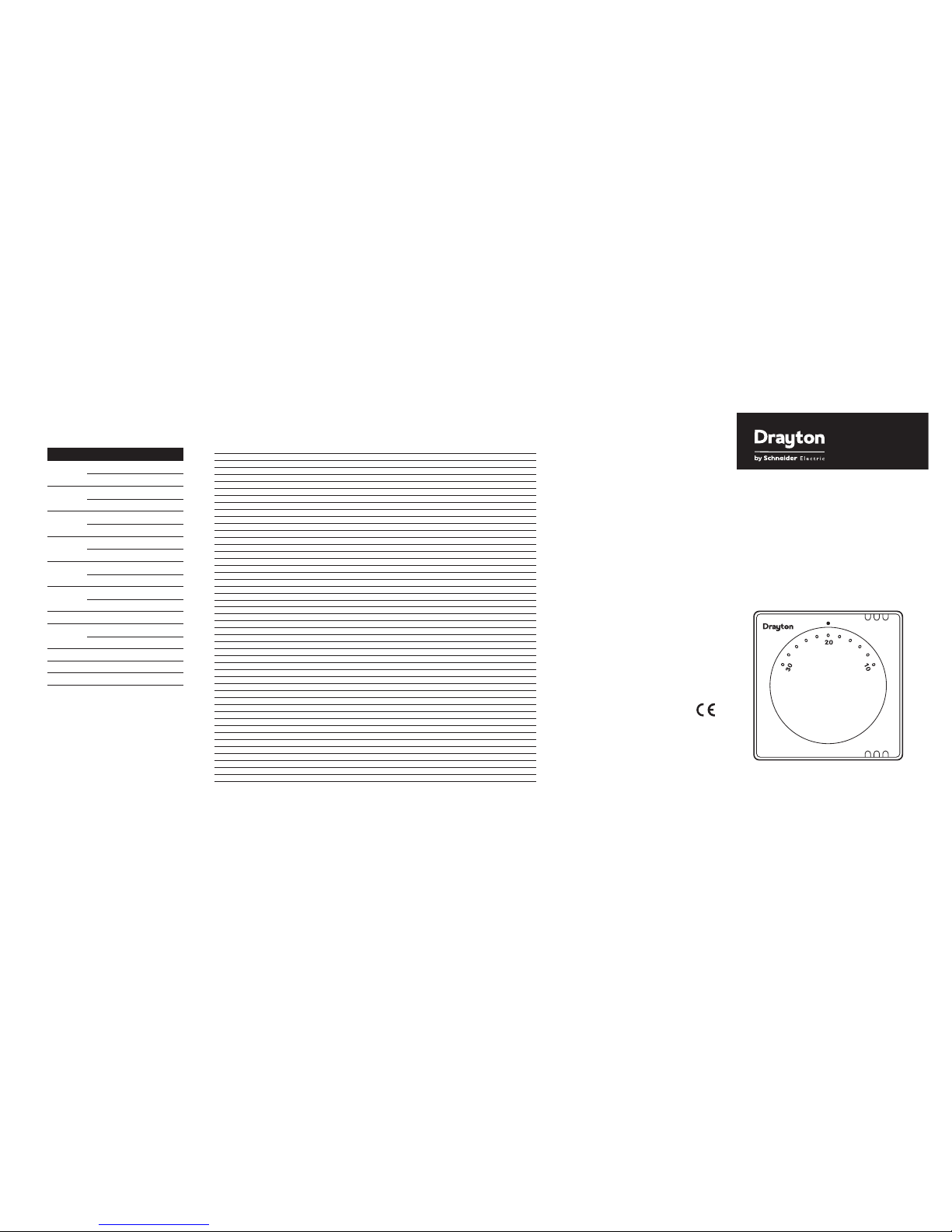
Combi-Stat RTS8
Room Thermostat
Installation
instructions
RELEVANT EC DIRECTIVES:
2006/95/EC Low Voltage Directive
2004/108/EC Electromagnetic Compatibility
2011/65/EU RoHS Directive
APPLIED STANDARDS:
EN60730-1, EN60730-2-9
Energy Class I = 1% (According to EU 811/2013,
812/2013, 813/2013, 814/2013)
Telephone: +44 (0) 845 130 5522
Facsimile: +44 (0) 845 130 0622
Technical Helpline: +44 (0) 845 130 7722
Website: www.draytoncontrols.co.uk
Email: customer.care@draytoncontrols.co.uk
6490018-1 Iss D
0503
Drayton Controls reserve the right
to make changes without notice
and cannot accept liability for errors.
THERMOSTAT INTERCHANGE GUIDE
deifsitaSdnameDnommoCeviLlartueNhtraEledoMekaM
3LN1SRsaG hsitirB
British Gas RS2 (for 2 wire connectionwith loads of 0.1 to 0.6 A) L 2
British Gas RS2 (for 2 wire connection with loads 0.6 to 6A) L 3
British Gas RS2 (for 3 wire connection with loads under 2A) N L 3
231LN4SR saG hsitirB
Drayton RTS7 and RTS8 (for 2 wire connection with loads of 0.1 to 0.6 A) L 2
Drayton RTS7 and RTS8 (for 2 wire connection with loads 0.6 to 6A) L 3
Drayton RTS7 and RTS8 (for 3 wire connection with loads under 2A) N L 3
3LN 1 STRnotyarD
3LN 2 STRnotyarD
231 LN4 STRnotyarD
214E241 STelytsefiL LCA
2315053 AT elytsefiL LCA
Drayton (old version) 3214 TR
Drayton (old version) 4ETR 123
3214032TMRlladnaR ssofnaD
43LN032TERlladnaR ssofnaD
Danfoss Randall RT1 132
2143DR lladnaR ssofnaD
214A3DR lladnaR ssofnaD
213NECTR lladnaR ssofnaD
213NEMTR lladnaR ssofnaD
213NERSR lladnaR ssofnaD
213N405R lladnaR ssofnaD
Honeywell T4360B 1 3
4312B0606T llewyenoH
4312B1606T llewyenoH
4312B3606T llewyenoH
4312B0636T llewyenoH
214E1TRH nnamtsroH
Horstmann Centuarstat 123
321E1 DAR ryG & sidnaL
Landis & Gyr RAD 1N 123
Landis & Gyr RAD 1EM 123
HLN1 TRP notrettoP
HLTN 2 TRP notrettoP
HLTNTS 001 TRP notrettoP
CHLTNTD 001 TRP notrettoP
134E2222 XLTcivnuS
13/LNE9522 XLT civnuS
213NE6532 XLT civnuS
134E4562 XLTcivnuS
2134E2582 XLTcivnuS
231E053 AT capoS
2314E153 AT capoS
23152 TRS retsamhctiwS
214ESS rewoT
NOTE: British Gas RS2 & Drayton RTS7 details are for guide use only. ALWAYS follow above instructions.
TECHNICAL DATA
Electrical supply 24V-230V AC/DC
Double insulated no earth
required
Temperature range 10°C to 30°C
Switch type SPST 6(2)A
See Figs 5 to 7 for supply
voltage and maximum loads
which are dependant on
wiring configuration used
Temperature sensor Bi metallic
Continued from overleaf
Combi-Stat boiler compatibilty information
Make Model
Alpha 240 2 wire
Ocean 80 3 wire
Ariston Genus 27 2 wire
Euro Combi 27 2 wire
Biasi Prisma 2 wire
Riva 3 wire
Chaffoteaux Britony Combi 80 3 wire
Celtic FF 3 wire
Ferrolli Domina 80 2 wire
Modena 80 2 wire
Halstead Finest 2 wire
Finest Gold 2 wire
Radiant RSF 24 2 wire
Ravenheat RSF 820/20 2 wire
CSI 85 Condensing 2 wire
Saunier Duval 623 Combi 2 wire
Myson Midas BF 2 wire
Elm Le Blanc 2 wire
CombiStat
Page 2

2. Undo the captive
restraining screw
3. Hinge from bottom
and pull top
forward. Lower
outer cover to
remove
4. Fix directly to a flat wall or onto a flush mounting
conduit box or optional Pattress box using suitable
screws
RTS8 Combi-Stat Thermostat
The RTS8 is a 24V-230V AC/DC mechanical thermostat
that can be used for either 2 or 3 wire applications,
making it suitable for replacement of older 2 wire
thermostats with no Neutral, or 3 wire thermostat
replacement where a Neutral connection has been
used. (Optimum performance is attained with 3 wire
connection.)
IMPORTANT NOTES
The installation instructions must be followed for this
thermostat to operate correctly. Failure to do so may
result in inadequate room temperature control.
Particular attention should be paid to the sections on
wiring and set up.
All electrical work should be carried out by a
competent person to conform to all relevant standards
and regulations.
Isolate/disconnect the power supply to the appliance
and/or system before commencing any electrical work.
A switch having a contact separation of at least 3mm
on both Live and Neutral poles must be incorporated
in the fixed wiring of the system to provide full
isolation of the mains supply.
Ensure that the system fuse is the correct rating. For
Gas fired radiator heating systems this is 3A.
INSTALLATION INSTRUCTIONS
Location
Care should be taken to mount the thermostat in a
position, which is not subject to direct sunlight or
draughts. Preferably it should be mounted on an inside
wall about 1.5m (5ft) above the floor in a position
where it can respond to room temperature but away
from the direct influence of radiators or other
appliances giving off heat.
Fixing
Standard cable entry
can be from the rear
or top, if bottom
entry or extra space
for cabling is
required use the
optional Pattress box.
1. Pull temperature
setting knob
forward to remove.
Set up to be followed when wiring to Fig 6 only
The thermostat utilises a series resistor as a heat
anticipator when wired in accordance with Fig 6
diagram.
To avoid inaccurate room temperature control it
is VERY IMPORTANT that the following set up
procedure is followed.
An electrical multimeter will be required for the
following procedure.
• Isolate electrical supply
• Mount base unit to wall
• Connect wires to L and 2
• Turn red setting shaft until switch contact opens
(see Fig 4)
• Set meter to 1 amp, current range
• Carry out electrical safety checks on the system/
appliance and turn system ON
• Put meter probes across L and 2
• Read current. Expected reading for Gas CH
systems = 0.1A to 0.6A
• If reading is BELOW 0.6Awire as Fig 6 (isolate
electric supply before rewiring)
• If reading is ABOVE 0.6Awire as Fig 7 (isolate
electric supply before rewiring)
• Reset the red setting shaft so that the small slot
is vertically downwards
• Reassemble thermostat
Range limiting
The setting range may be limited or a particular
setting locked through the use of the mechanism
to be found under the control knob.
To set the range limits:
1. Set thermostat to the desired temperature
2. Remove the setting knob by carefully pulling it
forward
3. Lift and rotate the two limiting arms to
reposition them in the required notches
4. Replace the knob in its previous position
Continued overleaf
Earth loop
connection
Red
setting
shaft
Screw
slots
Fig 1
Fig 4
N
2
3
L
Acc.
Acc.
Call for heat
LOAD
L
N
N
230V AC 50Hz
Fused 3A
Fig 5. 3 wire connection. Max load = 2A
Suitable for most wet CH systems
N
2
3
L
Acc.
Acc.
Call for heat
LOADLN
24V-230V AC/DC
Fused 3A
N
2
3
L
Acc.
Acc.
Call for heat
LOAD
L
N
24V-230V AC/DC
Suitably rated
fuse
Fig 7. 2 wire connection. No Neutral. Load = 0.6A to 6A
Typically for higher loads (ie electric heating)
Fig 3
Fig 2
Fig 6. 2 wire connection. No Neutral. Load = 0.1A to 0.6A
Suitable for most wet CH systems
Note: Use this connection for gas CH systems, where there is
no neutral wire, and follow set-up procedure. If current
reading above 0.6 amps, wire as Fig 7. 2 wire
connection no Neutral.
Wiring
The RTS8 is double insulated and does not require an
earth, if there are existing earth wires that need to be
connected, use the Earth loop connection (Fig 4).
Terminate the wiring as shown in diagrams (Figs 5 to
7), ensure that the correct diagram is followed to match
the current load (Amps) and cabling of the heating
system. If unsure of current load, follow Set up
procedure to determine it.
Combi-Stat boiler compatibilty information
Make Model
Worcester Series 2/3 wire*
CDi Series 2/3 wire*
Si Series 2/3 wire*
Vaillant EcoMax 2/3 wire*
TurboMax 2/3 wire*
Ideal Isar 2 wire
Response 2 wire
Mini 2 wire
Glow-Worm Energysaver 2/3 wire*
Compact E 2/3 wire*
Baxi 80 Eco 3 wire recommended
by Baxi across range
Combi 80E 3 wire recommended
by Baxi across range
105E 3 wire recommended
by Baxi across range
Maxflow 3 wire recommended
by Baxi across range
Potterton Bahama 3 wire recommended
by Pott’s across range
Puma 3 wire recommended
by Pott’s across range
Combi 3 wire recommended
by Pott’s across range
* Where 2/3 wire is indicated use 3 wire connection for
optimum performance.
This information is for guidance only as the boiler
manufacturer may change the mode of operation at any
time without warning. For further information please
refer to the boiler manufacturers handbook.
Combi-Stat boiler compatibilty information
Make Model
Worcester Series 2/3 wire*
CDi Series 3 wire
Si Series 2/3 wire*
Vaillant EcoMax 2/3 wire*
TurboMax 2/3 wire*
Ideal Isar 2 wire
Response 2 wire
Mini 2 wire
Glow-Worm Energysaver 2/3 wire*
Compact E 2/3 wire*
Baxi 80 Eco 3 wire recommended
by Baxi across range
Combi 80E 3 wire recommended
by Baxi across range
105E 3 wire recommended
by Baxi across range
Maxflow 3 wire recommended
by Baxi across range
Potterton Bahama 3 wire recommended
by Pott’s across range
Puma 3 wire recommended
by Pott’s across range
Combi 3 wire recommended
by Pott’s across range
* Where 2/3 wire is indicated use 3 wire connection for
optimum performance.
This information is for guidance only as the boiler
manufacturer may change the mode of operation at any
time without warning. For further information please
refer to the boiler manufacturers handbook.
 Loading...