

Drayton RF701, 22092, RF700, 22090, Digistat RF700/22090 Installation Instructions Manual
...
Installation Instructions
WARNING
If you do not have the knowledge to install the SCR safely then
you must arrange for a competent electrician to install it for
you. Wiring must conform to the current IEE regulations.
Prior to commencing the installation you must ensure the
mains supply is switched off.
INSTALLATION OF SCR RECEIVER
Read all installation and commissioning instructions before
proceeding. Do not switch on until ready to commission.
The system wiring must be able to be fully disconnected from the
mains supply by a switch incorporated in the fixed wiring having a
contact separation of at least 3mm on both poles. Fused at 3A.
LOCA
TION
The Digistat SCR (receiver) should be mounted in a convenient
position, close to the boiler or central heating system.
For the best performance install in an open space, at least
30cm distance from any metal objects including wall boxes
and boiler housing.
It is recommended that the SCR is mounted on the wall nearest
the final location of the Digistat+RF programmable room
thermostat and not less than 30cm from the boiler side panel.
Warning: Installing the SCR too close to the metal side
panel or mains cables may interfere with the radio signal.
ON
RECEIVE / ALARM
OVERRIDE
LEARN
MODE
1
2
This product is double insulated and does not require an earth
connection. The SCR should be wired to the boiler or central
heating wiring using the correct type of cable or flex. The SCR
should be wired in to replace hard wired room or programmable
thermostats shown on the system or boiler wiring diagrams. Always
check other manufacturers instructions for compatibility.
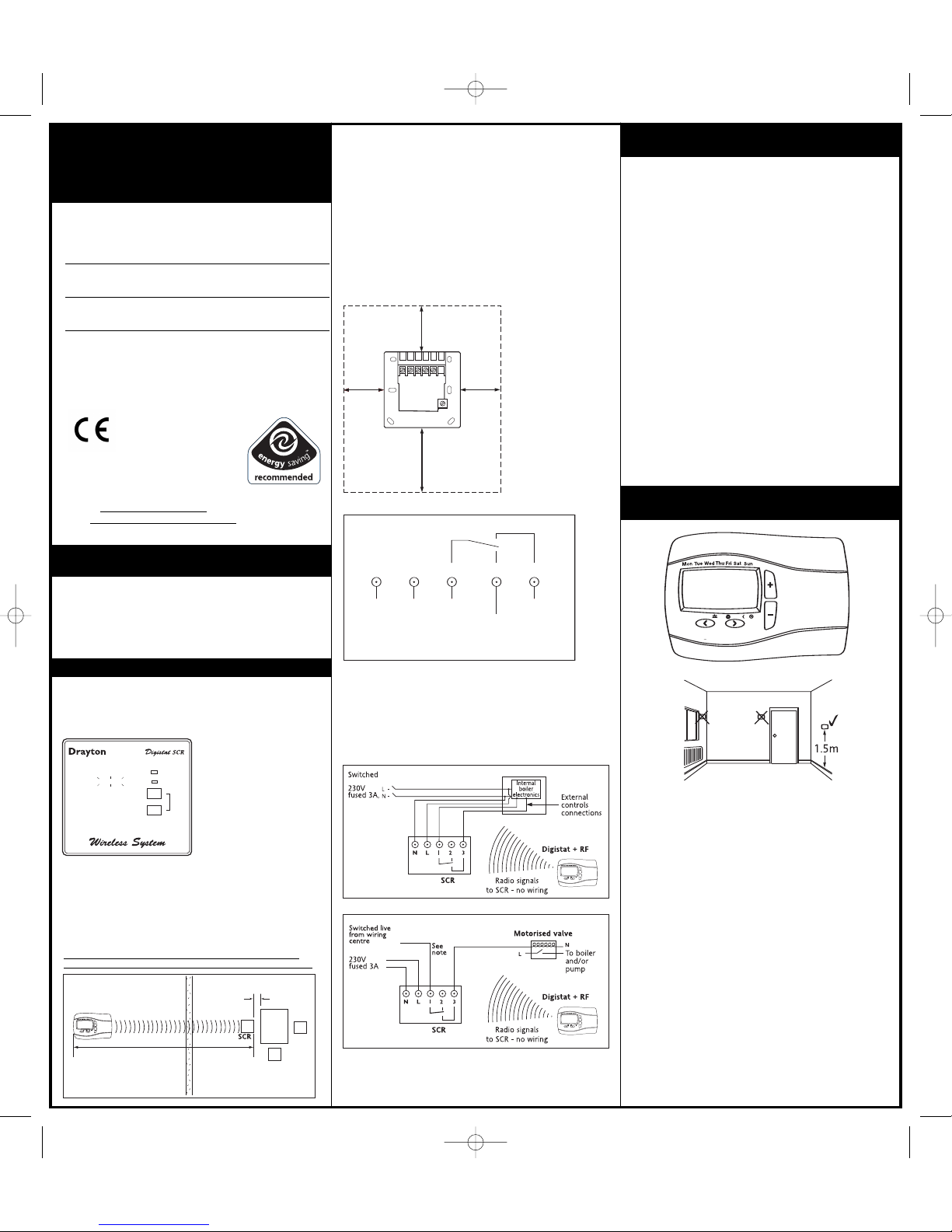
S
CR wallplate clearances
Electrical
Dra yton
Digistat +2RF/+3RF
Invensys Controls Europe
Customer Service Tel: 0845 130 5522
C
ustomer Service Fax: 0845 130 0622
T
echnical Helpline Tel: 0845 130 7722
W
ebsite: www
.
draytoncontrols.co.uk
Email: customer.care@invensyscontrols.com
User Guide 06490099001 IssA
Programmable Room
Thermostat Wireless
Model: RF700/22090
Model: RF701/22092
Power Supply:
Battery - Thermostat
Mains - Digistat SCR
Certification Mark
N L 1 2 3 4
50 mm
minimum
c
learance
40 mm
minimum
clearance
40 mm
minimum
clearance
70 mm
minimum
clearance
Combi boiler basic wiring layout
Zone control basic wiring layout
Note: If the Digistat +2RF or +3RF is used without a separate
programmer
, or the programmer is set constantly on it would be
acceptable to link ‘L’ to ‘1’ provided the output voltage required
is 230V ac.
H
o
l
Ma
n
A
ut
oD
a
y
Drayton
Digistat +2RF
Ho
l
Ma
n
Auto
Da
y
Drayton
Digistat +2RF
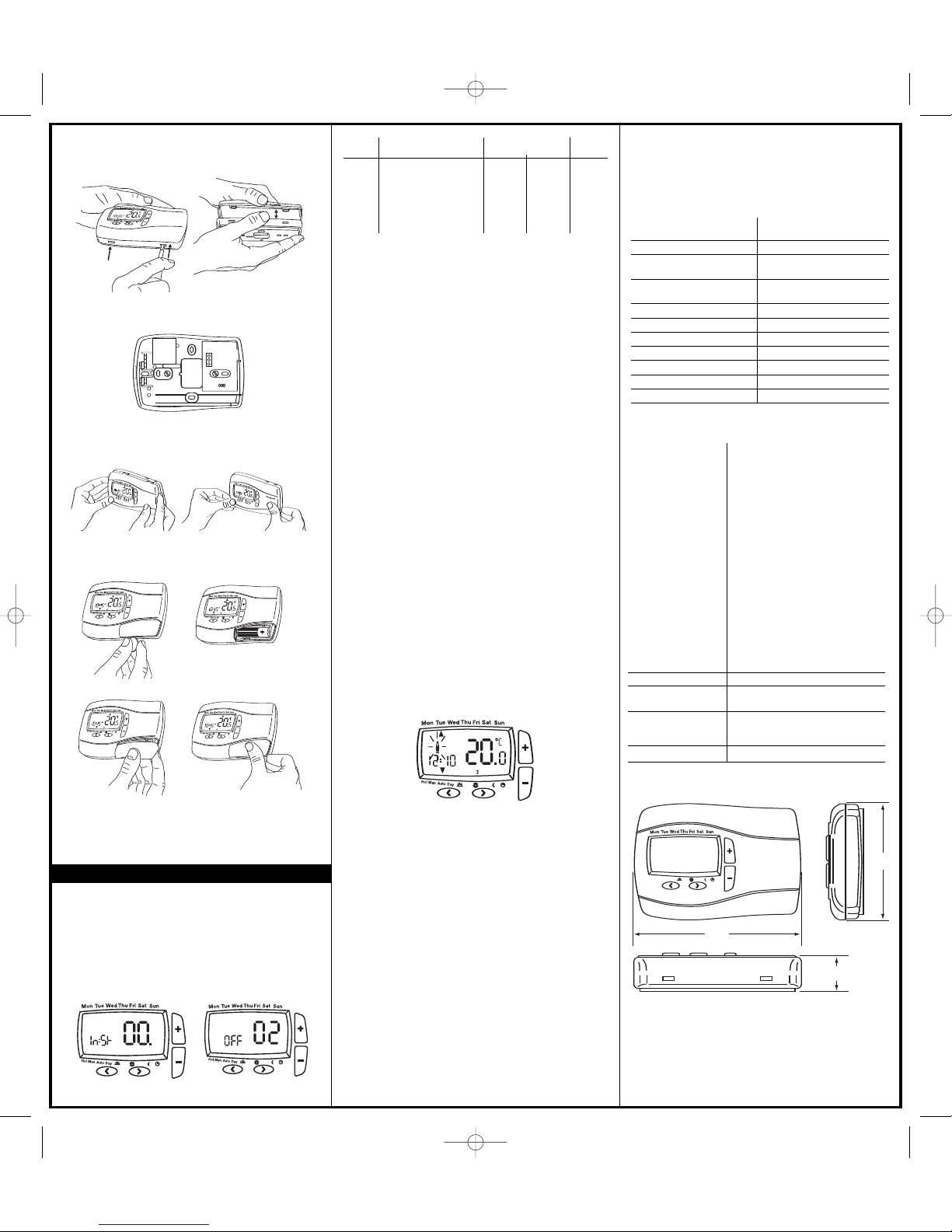
FIXING (
minimum wall plate clearances shown)
1
.
L
oosen the securing screws, remove the wallplate, and if
surface wiring is to be used, snap out the cable entry strip
o
n the bottom edge of the wallplate with a pair of pliers.
2. Fix the wallplate, terminals at the top, either direct onto the
f
lat wall using wall plugs and no 6 x1” wood screws or on a
plastic flush mounting single conduit box using M3.5 x 14 screws.
M
inimum wallplate clearances are shown.
3.C
omplete the wiring to the SCR wallplate in accordance
with the relevant diagram, to comply with current IEE
r
egulations.
4. Place the SCR onto the wallplate and tighten the securing
s
crews.
N L 1 2 3
230V ac 50Hz
Fused 3A
Common
heating
satisfied
or call for
cooling
Call for
heat
V
olt free contacts
ac
ac
Location
The Digistat +2RF/+3RF is a radio frequency device and for best
performance should be mounted in an open space, not less
than 30cm distance from any metal objects, including wall
boxes.
Care should be taken to mount the
Digistat +2RF/+3RF on a
wall, in a postion which is not subject to direct sunlight or
draughts. Preferably it should be mounted on an inside wall
about 1.5m (5ft) above the floor in a position where it can
respond to room temperature, but away from the direct
influence of radiators or other appliances giving off heat.
Signal Strength
Before fixing the Digistat +2RF/+3RF to the wall it is
recommended to first check the signal strength from that
location.
To do this, remove the batteries, press and hold the + button
whilst refitting the batteries. The display now shows rF which
indicates that the
Digistat +2RF/+3RF is continuously sending an
OFF signal to the SCR (receiver). Leave the
Digistat +2RF/+3RF
in position and return to view the SCR. If the RED LED is
continuously flashing, this indicates a good signal. If the RED
LED is not flashing, this indicates a poor signal and you need to
reposition the
Digistat +2RF/+3RF until the RED LED is flashing.
When the signal strength has been confirmed remove the
batteries to cancel the test and follow the installation
instructions 1-7 as follows.
1. Turn off the power supply to the Digistat SCR (receiver unit)
a
nd leave for 5 seconds.
2.T
urn on power to SCR unit and check red light is on.
3.P
ress override button No.2 and check the green light comes
o
n and boiler fires.
4.P
ress & hold down button No.1 (Keep depressed), then
p
ress No.2 and keep depressed. {The Red LED light will flash
a couple of times and then it will go out}
5. Now release both the buttons – {the two LED lights should
c
ome back on}
6. Get the Digistat+2RF/+3RF unit and stand two metres away
f
rom the SCR unit with the Digistat+2RF/+3RF unit in your hand.
7.R
emove the battery cover and fit the batteries.
8.T
he Red LED light on the SCR will now flash for approx. 7
s
econds.
9.T
his confirms that the radio signal is being sent and
r
eceived.
10.T
he Digistat+2RF/+3RF and the SCR are now successfully
linked by a dedicated RF address.
11. Install the Digistat+2RF/+3RF as follows:
COMMISSIONING THE DIGISTAT +2RF or
+3RF ‘WIRELESS SYSTEM’
I
MPORTANT: MULTIZONE INSTALLATIONS ONLY
I
f more than one ‘wireless system’ is fitted within the same
property ie. for controlling 2 or more zones (multi-zone) it is
essential that the Digistat +RF units are matched correctly to
the relevant SCR. This is easily achieved by commissioning each
D
igistat +RF and SCR in turn.
INSTALLATION OF THE DIGISTAT +2RF or
+3RF PROGRAMMABLE THERMOSTAT
Hol
Man
Auto
Day
Drayton
Digistat +2RF
Ho
l
M
an
Au
to
Da
y
Drayton
Digistat +2RF
BOILER
✔
✔
✘
✘
30cm Min
Preferred side of boiler
The range may be affected by
composition/density and number of walls
between the Digistat +RF and SCR
Radio Signal Range:
30m Typically
06490099001 IssA 24-1-07 13/2/07 12:05 Page 1
(
Option 02)
F
reeze Protection
Freeze protection will switch on the heating if the room
t
emperature falls to 5ºC and will then control the temperature at
7
ºC even if the
D
igistat+2RF/+3RFis in OFF mode.
The Freeze Protection default in ON.
To switch off the Freeze Protection mode enter the Installer
O
ptions Menu (Refer to Installer Options 02) and change to OFF.
P
ress > to accept.
(
Option 04 & 05)
L
ow and High Limit set points.
The user temperature set points defaults are High 32ºC and Low
5
ºC, to change these limits enter the Installer Options Menu
(
Refer to Installer Options 04 & 05).
(
Option 06)
I
ntelligent Delayed Start (Energy saving feature).
T
he Intelligent Delayed Start is an energy saving feature which
automatically reduces the warm up time for the heating system.
As the weather becomes milder, Intelligent Start will delay the
h
eating start times so that fuel is not wasted bringing the room
up to temperature earlier than necessary.
Note: Intelligent Delayed Start only applies in Auto mode.
I
ntelligent Delayed Start default is in OFF mode.
T
o switch ON Intelligent Delayed Start enter the Installer Options
Menu (Refer to Installer Options 06).
Note the Intelligent Delayed start option is not suitable for
H
ydronic underfloor application.
Ensure Installer option 06 is set to OFF before final commissioning
for Hydronic underfloor application.
Special Note:
If the Intelligent delayed start feature is enabled, (Off
changed to On in Installer option 06), please inform the end
user of this feature.
The following special note has been added to the user
instruction to explain the adjustment requirement:
When the delay period is operating indicated by the flame symbol
flashing (Fig12), pressing any button returns the Digistat +2/3RF
to auto mode allowing normal button operation until the next
time/ temperature event, when it will resume the delay start
mode or follows the Holiday, Manual, Override or Off modes as
selected.
Changes to the installer options and pre-set programmes must be
made with the flame symbol not flashing.
(Option 10)
Valve Protection
In some hydronic heating systems there may be a requirement to
protect the valve by operating it once a day, for a given period,
without bringing on the heating system.
If valve protection is selected the valve will be operated for a
period as shown in V
alve protection time (mins).
Valve protection time every day at 10.00am.
V
alve protection default is OFF
.
T
o enable the valve protection mode enter the Installer Options
Menu (Refer to Installer Option 10).
(Option 11)
Valve Protection time (mins).
Valve protection time can be set between 1 and 5 minutes
(default 3 minutes).
To change this once a day on time enter the Installer Options
Menu (Refer to Installer Option 11).
Digistat +RF Programmable Room Thermostats are available
in 2 models.
Digistat +2RF = 24 Hour,Programs are the same every day
(Monday to Sunday)
Digistat +3RF = 5-2 day
/
7day
,
allows you to set programs for
week days and weekends or different programs for every day of
the week.
Display Error code E1
Installer
O
ptions What is it Select between Default
0
2 Freeze Protection On Off On
0
4 Low Set Point °C 5 High Limit 5
05 High Set Point °C Low Limit 32 32
0
6 Delayed Start
(
Energy saving feature) On Off Off
1
0 Valve Protection On Off Off
11 Valve Protection Time
(Mins) 15 3
(Fig 7)
(Fig 8)
INSTALLER OPTIONS
If you wish to change any of the Installer Options as shown
below, enter the Installer Option Menu from Auto mode by
pressing < and + simultaneously for 5 seconds.
Pressing < and + again for 5 seconds will exit the Menu and
return to Auto mode.
Once the Installer Options screen has been selected (Fig 7), the
< and > buttons allow you to scroll through the Menu (shown
below). The + and - allow you to change values. Once a value
has been changed pressing > before exiting the Menu will save
the new setting. (Fig 8 shows Option 02 OFF).
7. The Digistat +2RF/+3RF is now installed and will automatically
start to control the room temperature according to the
pre-set program 1 as shown in the User Guide.
The display shows the correct time and date which is
automatically set together with the actual room temperature.
(Fig 6)
Dig
ist
at +
2R
F
Dig
ist
at +
2R
F
Dra
yto
n
Dra
yto
n
Dig
is
t
at
+2
RF
Dra
yto
n
6. Replace battery cover (fig 6).
4. Re
move the battery cover using a coin (Fig 4).
5. Install the 2 AA batteries provided (Fig 5).
(Fig 5)
(Fig 4)
D
r
a
yt
on
D
i
g
i
s
t
at +
2R
F
D
i
g
i
s
t
at +
2R
F
D
ig
is
t
at
+2R
F
D
ig
is
t
at +2R
F
D
r
a
yt
on
Dra
yto
n
Dra
yto
n
Dra
yto
n
D
ig
ist
at +2
R
F
D
ig
ist
at
+2
R
F
Dra
yto
n
Installation
1.
Remove the front cover using a flat screwdriver and separate
f
rom back plate (Fig 1).
(Fig 3)
Dr
a
y
t
o
n
(Fig 2)
D
ra
yt
on
(Fig 1)
3.R
eplace the front cover by locating in position and pushing
fully onto the back cover (Fig 3).
2.F
ix the back plate directly onto the wall using suitable wall
p
lugs and screws (Fig 2).
Hol
Man
Auto
Day
96.5
31.3
137.0
Drayton
Digistat +2RF
P
ower supply 2 X 1.5V IEC LR6 (AA)
a
lkaline batteries
B
attery life 2 years typical
A
mbient temperature Operating 0°C to 40°C
S
torage – 20°C to 55°C
A
mbient humidity Operating 25% to 90%
(
non condensing) Storage 15% to 95%
T
emperature range 5°C to 32°C
Accuracy (between 5°C & 32°C) 0.5K
Timing resolution 1 minute
Temperature resolution 0.5K
B
all pressure test 75 °C
P
ollution situation Degree 2
Protection level IP30
Dimensions
Technical Data Digistat +2RF/+3RF
Technical Data SCR (Receiver)
Applicable Standards: BS EN60730-1
BS EN60730-2-7
B
S EN60730-2-9
E
TSI EN 300 220-3
Electromagnetic compatibility and
radio spectrum Matters (ERM);
Short Range Devices (SRD).
ETSI EN 301 489-3
Electromagnetic compatibility and
radio spectrum Matters (ERM); EMC
s
tandard for radio equipment and
services; Part 3: Specific conditions for
Short Range Devices (SRD) operating
on frequencies between 6 kHz and
40 GHz.
73/23/EEC Low Voltage Directive
89/336/EEC EMC Directive
93/68/EEC Marking Directive
1999/5/EC R&TTE Directive
Power Supply: 230V ac 50Hz
Switch Type & Rating: SPDT (voltage free) 2(1)A 230V ac
or 24V ac/dc
Wiring: Designed for fixed wiring only, to
comply with current IEE
regulations.
Reception Frequency: 433 MHz
(Fig 12)
When the display shows an error code (E1) this indicates a
s
ensor fault and the heating system will remain Off. Please
c
ontact your local heating service engineer to replace your
D
igistat +2RF/3RF.
06490099001 IssA 24-1-07 13/2/07 12:05 Page 2
 Loading...