

Page 1
Models:
13616/13618/13619
Page 2
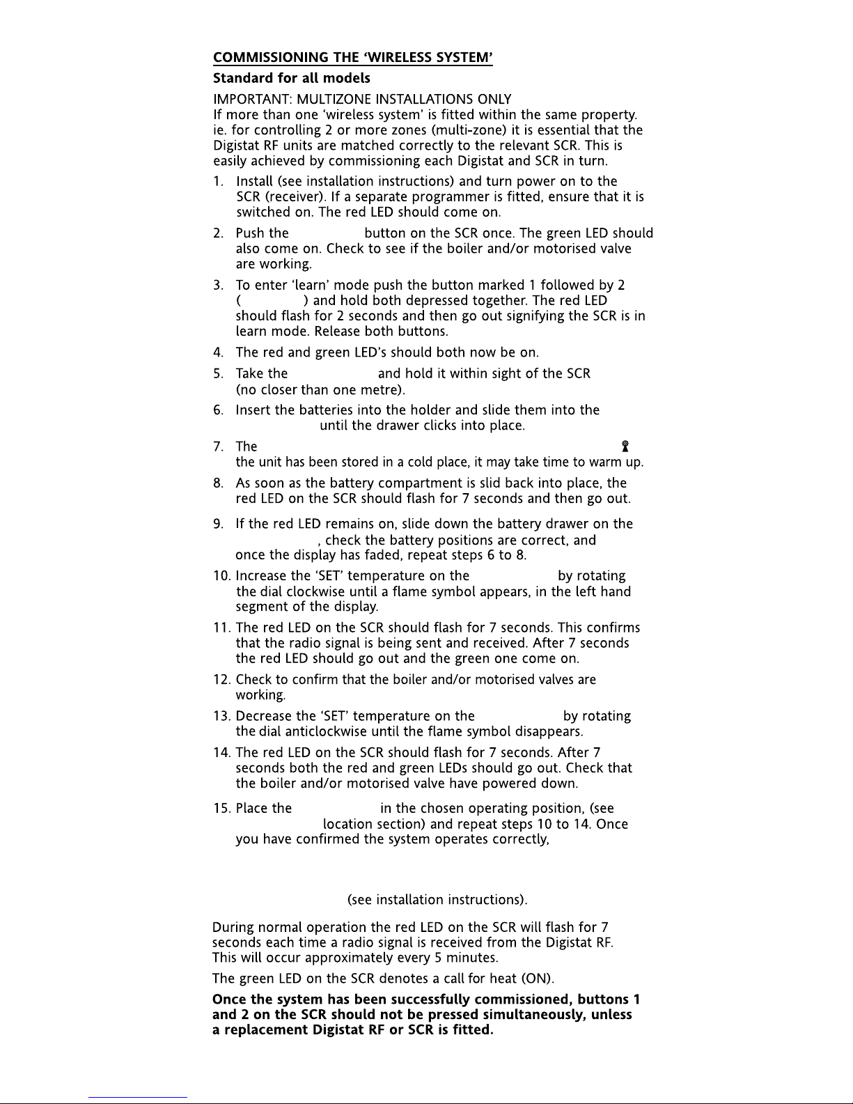
On
Receive / Alarm
Boost 1 Hr
1
2
Learn
Mode
Digistat+C
SCR
Wireless System
Page 3
BOILER
4
4
8
8
3
0cm Min
Preferred side of boiler
The range may be affected by
composition/density and number of walls
between the Digistat +CRF and SCR
Radio Signal Range:
30m Typically
S
CR
Page 4
230V a.c.
Heating
DHW Cylinder Thermostat
230V a.c.
Digistat+C RF
Page 5
‘Boost 1 Hr’
Digistat+C RF
Digistat+C RF
Digistat+C RF should now display the ‘E2’ and the RF symbol ‘ ’. If
Digistat+C RF
Digistat+C RF
Digistat+C RF
Digistat+C RF
the
Digistat+C RF transmitter unit and sensor can be installed.
When the sensor is wired to the transmitter unit, the display will
change after approx. 30 seconds to show the current setpoint and
‘E2’ will disappear
Digistat+C RF
Boost 1 Hr
Page 6

To assist with commissioning or checking the system operation,
there is a positive OFF setting outside the temperature scale on the
cylinder thermostat. First adjust the minimum temperature setting
to 40oC as described in the user guide, then rotate the dial fully
anticlockwise for OFF.
‘
Signal Strength
Before fixing the Digistat+C RF to the wall it is recommended to first
check the signal strength from that location.
To do this, remove the batteries, press and hold the ‘set’ button whilst
refitting the batteries, keep the ‘set’ button held and after a few
seconds the display will show ‘rF’ which indicates that the Digistat+C RF
is continuously sending an OFF signal to the SCR (receiver). Leave the
Digistat+C RF in position and return to view the SCR. If the red LED is
continuously flashing, this indicates a good signal. If the red LED is not
flashing, this indicates a poor signal and you need to reposition the
Digistat+C RF until the red LED is flashing.
When the signal strength has been confirmed remove the batteries to
cancel the test and follow the installation instructions.
Page 7

Unclip the housing to show the terminal block. First, connect a 2-core
cable to the Digistat+C RF transmitter, cut to the required length to
reach the sensor position. Connect to the sensor in the position shown
and fold wires back through the cable grip & out through the cable
entry, re-assemble the housing.
Page 8

Page 9

Relevant EC Directives:
Applied Standards:
230V a.c.
of walls between the Digistat +C RF and SCR.
+0/-8
230V a.c.
24V a.c./d.c.
(BS7671).
2006/95/EC Low Voltage Directive
2004/108/EC Electromagnetic Compatibility
Directive
1999/5/EC R&TTE Directive
2006/66/EC Battery Directive
EN60730-1; EN60730-2-9
ETSI EN 300 220-3, ETSI EN 301 489-3
Page 10

Models:
13616/13618/13619
Page 11

Simple Setting or Operating
To set the required temperature
•The display normally shows the current setpoint.
•To adjust the required temperature, turn the
dial clockwise to increase or anti-clockwise to
decrease, (1 click = 5ºC), the LCD will display
the temperature setpoint as it is being
adjusted and ‘SET’ will be displayed. After a
few seconds the display will return
to normal
operation and will display the current setpoint.
Page 12

Default Settings
The maximum and minimum setpoints are preset in the factory to
65
o
C and 60oC respectively.
Page 13

The hot water can be manually switched on and off by using the
‘Boost 1 Hr’ button on the SCR in a fault situation, even though
the red LED will stay on until a satisfactory signal is reinstated.
When the hot water is turned on by pressing the ‘Boost 1 Hr’
button, it will time out after 1 hour and return to OFF.
the Digistat+C RF unit.
the Digistat+C RF unit are
the Digistat+C RF
the Digistat+C RF
P
Page 14

Proper Battery Recycling
Electronic devices and batteries, rechargeable or not, should not be
disposed of into ordinary household waste. Instead, they must be
recycled properly to protect the environment and cut down the waste
of precious resources. Your local waste management authority can
supply details concerning the proper disposal of batteries.
In compliance with the EU Directive 2006/66/EC, the button cell
battery located on the printed circuit board inside this product, can be
removed at the end of product life, by professional personnel only.
Page 15

 Loading...