

Page 1
i
Page 2

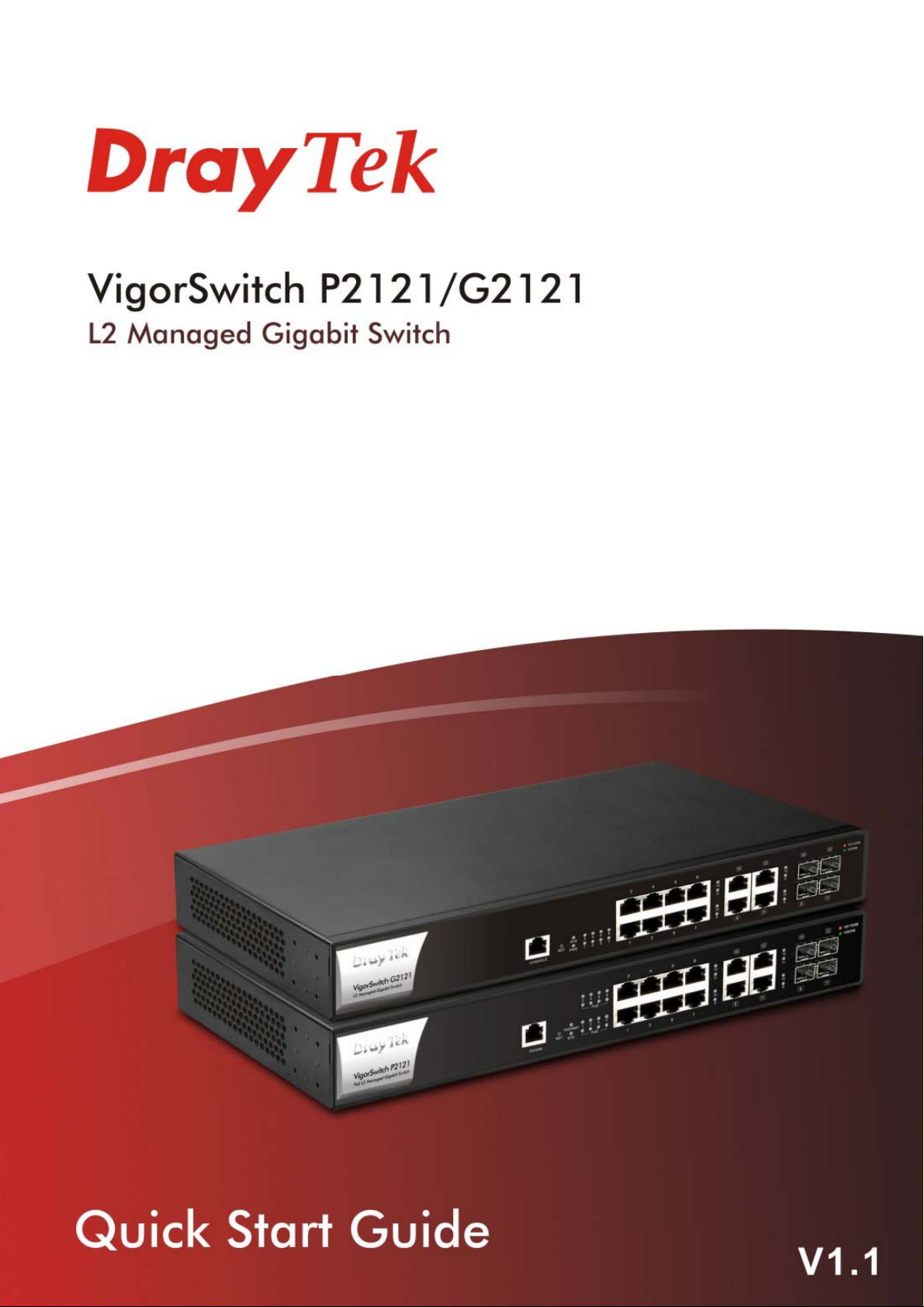
VigorSwitch P2121/G2121
L2 Managed Gigabit Switch
Quick Start Guide
Version: 1.1
Firmware Version: V2.5.1
(For future update, please visit DrayTek web site)
Date: December 25, 2019
ii
Page 3

Intellectual Property Rights (IPR) Information
Copyrights
Trademarks
© All rights reserved. This publication contains information that is protected
by copyright. No part may be reproduced, transmitted, transcribed, stored in
a retrieval system, or translated into any language without written permission
from the copyright holders.
The following trademarks are used in this document:
Microsoft is a registered trademark of Microsoft Corp.
Windows, Windows 95, 98, Me, NT, 2000, XP, Vista, 7, 8 and Explorer are
trademarks of Microsoft Corp.
Apple and Mac OS are registered trademarks of Apple Inc.
Other products may be trademarks or registered trademarks of their
respective manufacturers.
Safety Instructions and Approval
Safety
Instructions
Read the installation guide thoroughly before you set up the switch.
The switch is a complicated electronic unit that may be repaired only be
authorized and qualified personnel. Do not try to open or repair the
switch yourself.
Do not place the switch in a damp or humid place, e.g. a bathroom.
Do not stack the switches.
The switch should be used in a sheltered area, within a temperature
range of 0 to +45 Celsius.
Do not expose the switch to direct sunlight or other heat sources. The
housing and electronic components may be damag ed by dire ct sunlight or
heat sources.
Do not deploy the cable for LAN connection outdoor to prevent electronic
shock hazards.
Keep the package out of reach of children.
When you want to dispose of the switch, please follow local regulations
on conservation of the environment.
Warranty
We warrant to the original end user (purchaser) that the switch will be free
from any defects in workmanship or materials for a period of one (1) year from
the date of purchase from the dealer. Please keep your purchase receipt in a
safe place as it serves as proof of date of purchase. During the warranty
period, and upon proof of purchase, should the product have indications of
failure due to faulty workmanship and/or materials, we will, at our discretion,
repair or replace the defective products or components, without charge for
either parts or labor, to whatever extent we deem necessary tore-store the
product to proper operating condition. Any replacement will consist of a new
or re-manufactured functionally equivalent product of equal value, and will
be offered solely at our discretion. This warranty will not apply if the produ ct
is modified, misused, tampered with, damaged by an act of God, or subjected
to abnormal working conditions. The warranty does not cover the bundled or
licensed software of other vendors. Defects which do not significantly affect
the usability of the product will not be covered by the warranty. We reserve
the right to revise the manual and online documentation and to make changes
from time to time in the contents hereof without obligation to notify any
person of such revision or changes.
iii
Page 4
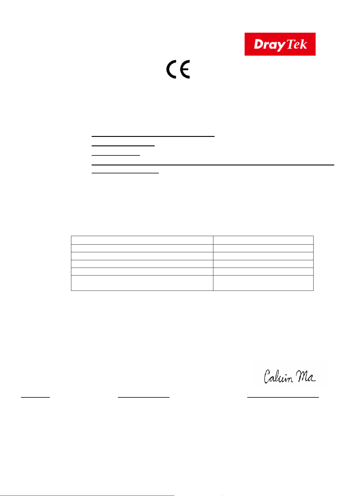
EU Declaration of Conformity
We DrayTek Corp. , office at No.26, Fu Shing Road, HuKou County, Hsin-Chu Industry Park, Hsinchu
300, Taiwan , R.O.C., declare under our sole responsibility that the product
Product name: 8 + 4 Combo GbE Ports PoE Switch
Model number: VigorSwitch P2121
Manufacturer: DrayTek Corp.
Address: No.26, Fu Shing Road, HuKou County, Hsin-Chu Industry Park, Hsinchu
300, Taiwan , R.O.C.
is in conformity with the relevant Union harmonisation legislation:
EMC Directive 2014/30/EU, Low Voltage Directive 2014/35/EU and RoHS 2011/65/EU with
reference to the following standards
Standard Version / Issue date
EN 55032 2012+AC:2013 class A
EN 61000-3-2 2014 Class A
EN 61000-3-3 2013
EN 55035 2017
EN 62368-1 2014 +A11:2017 (Second
Edition)
Hsinchu October 3, 2019 Calvin Ma / President
(place) (date) (Legal Signature)
iv
Page 5
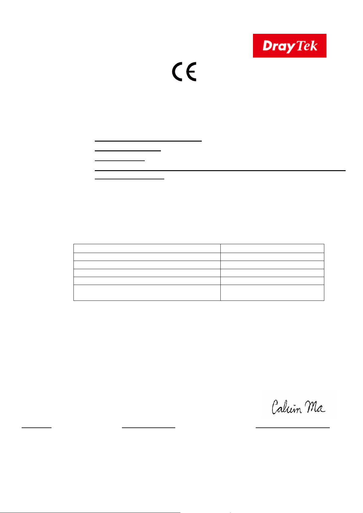
EU Declaration of Conformity
We DrayTek Corp., office at No.26, Fu Shing Road, HuKou County, Hsin-Chu Industry Park, Hsinchu
300, Taiwan , R.O.C., declare under our sole responsibility that the product
Product name: 8 + 4 Combo GbE Ports Switch
Model number: VigorSwitch G2121
Manufacturer: DrayTek Corp.
Address: No.26, Fu Shing Road, HuKou County, Hsin-Chu Industry Park, Hsinchu
300, Taiwan , R.O.C.
is in conformity with the relevant Union harmonisation legislation:
EMC Directive 2014/30/EU, Low Voltage Directive 2014/35/EU and RoHS 2011/65/EU with
reference to the following standards
Standard Version / Issue date
EN 55032 2012+AC:2013 class A
EN 61000-3-2 2014 Class A
EN 61000-3-3 2013
EN 55035 2017
EN 62368-1 2014 +A11:2017 (Second
Edition)
Hsinchu October 3, 2019 Calvin Ma / President
(place) (date) (Legal Signature)
v
Page 6

Regulatory Information
Federal Communication Commission Interference Statement
This equipment has been tested and found to comply with the limits for a Class A digital device,
pursuant to Part 15 of the FCC Rules. These limits are designed to provide reasonable protection
against harmful interference in a residential installation. This equipment generates, uses and can
radiate radio frequency energy and, if not installed and used in accordance with the instructions, may
cause harmful interference to radio communications. However, there is no guarantee that
interference will not occur in a particular installation. If this equipment does cause harmful
interference to radio or television reception, which can be determined by turning the equipment off
and on, the user is encouraged to try to correct the interference by one of the following measures:
Reorient or relocate the receiving antenna.
Increase the separation between the equipment and receiver.
Connect the equipment into an outlet on a circuit different from that to which the receiver
is connected.
Consult the dealer or an experienced radio/TV technician for help.
This device complies with Part 15 of the FCC Rules. Operation is subject to the following two
conditions:
(1) This device may not cause harmful interference, and
(2) This device may accept any interference received, including interference that may cause
undesired operation.
Company name ABP International Inc.
USA Local
Representative
Caution: Any changes or modifications not expressly approved by the party responsible for
compliance could void the user's authority to operate the equipment.
Address 13988 Diplomat Drive Suite 180 Dallas TX 75234
ZIP Code 75234 E-mail [email protected]
Contact Person Mr. Robert
Messer
Tel. 19728311600
More update, please visit www.draytek.com
.
v
Page 7

Be a Registered Owner
Web registration is preferred. You can register your Vigor switch via http://www.draytek.com.
Firmware & Tools Updates
Due to the continuous evolution of DrayTek technology, all switches will be regularly upgraded.
Please consult the DrayTek web site for more information on newest firmware, tools and
documents. http://www.draytek.com
vi
Page 8
Paacckkaaggee
P
The 8 ports + 4 Combo UTP/SFP ports, L2 Managed Gigabit Ports Switch is a
standard switch that meets both IEEE 802.3u/ab Fast Ethernet and Gigabit
Ethernet specifications.
The network administrator can logon the switch to monitor, configure and
control each port’s activity. In addition, the switch implements the QoS (Quality
of Service) and VLAN. It is suitable for office application.
Coonntteenntt
C
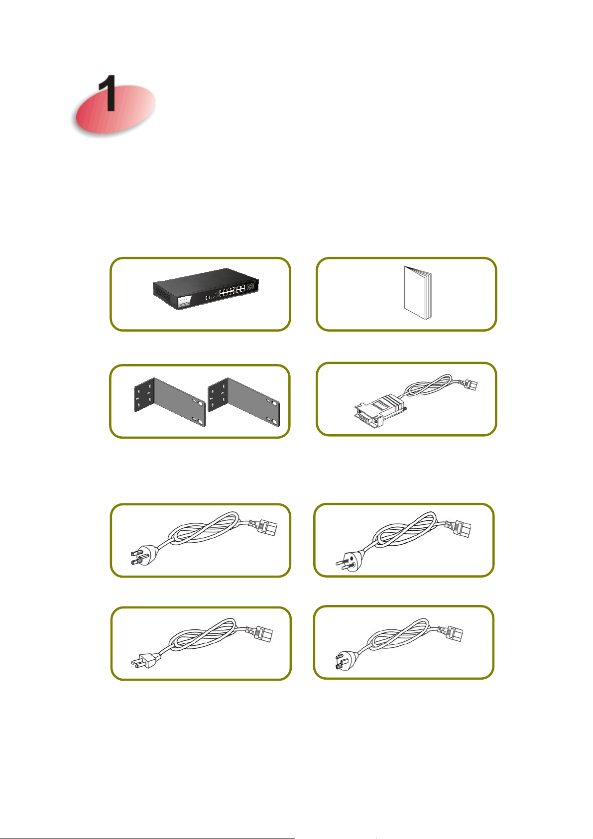
VigorSwitch
Rack Mount Kit (brackets)
The type of the power cord depends on the country that the switch will be
installed.
UK-type Power Cord
EU-type Power Cord
Quick Start Guide
Console Cable
USA/Taiwan-type Power Cord
If any of these items is found missing or damaged, please contact your local
supplier for replacement.
AU/NZ-type Power Cord
1
Page 9
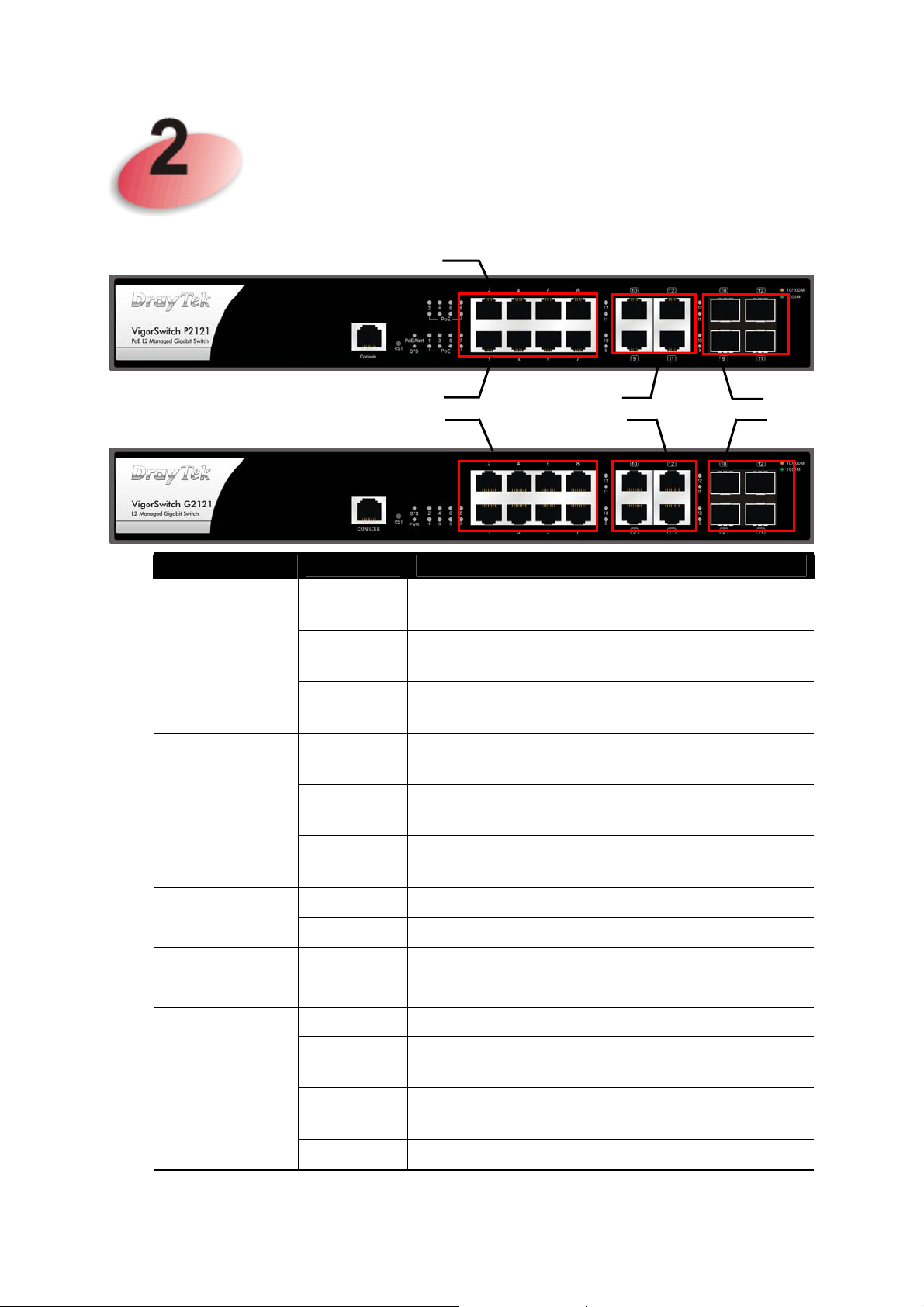
Paanneell
P
PoE for Port 1 to Port 8
Exxppllaannaattiioonn
E
RJ45 LNK/ACT
LED
PoE/Alert
(for P2121)
Port 1 to Port 8
Status Explanation
On (Green) Devices connected over the PoE maximum
power budget.
Blinking
(Green)
More than 80% of maximum power budget is
supplied for PoE device(s).
Combo
Port
SFP
LNK/ACT
SYS
PWR
PoE 1~8
RJ 45 LNK/ACT
Port 1 ~ 8
Off Devices connected within the PoE maximum
power budget.
On (Green)
Blinking
(Green)
Off
On The device is powered on.
Off The device is powered off.
On (Green) The port is supplied with PoE power.
Off No PoE power is supplied on the port.
On (Green) The device is connected with 1000Mbps.
On
(Amber)
Blinking The system is sending or receiving data
The switch finishes system booting and the
system is ready.
The switch is powered on and starts system
booting.
The power is off or the system is not ready /
malfunctioning.
The device is connected with 10/100Mbps.
through the port.
Off The port is disconnected or the link is failed.
2
Page 10
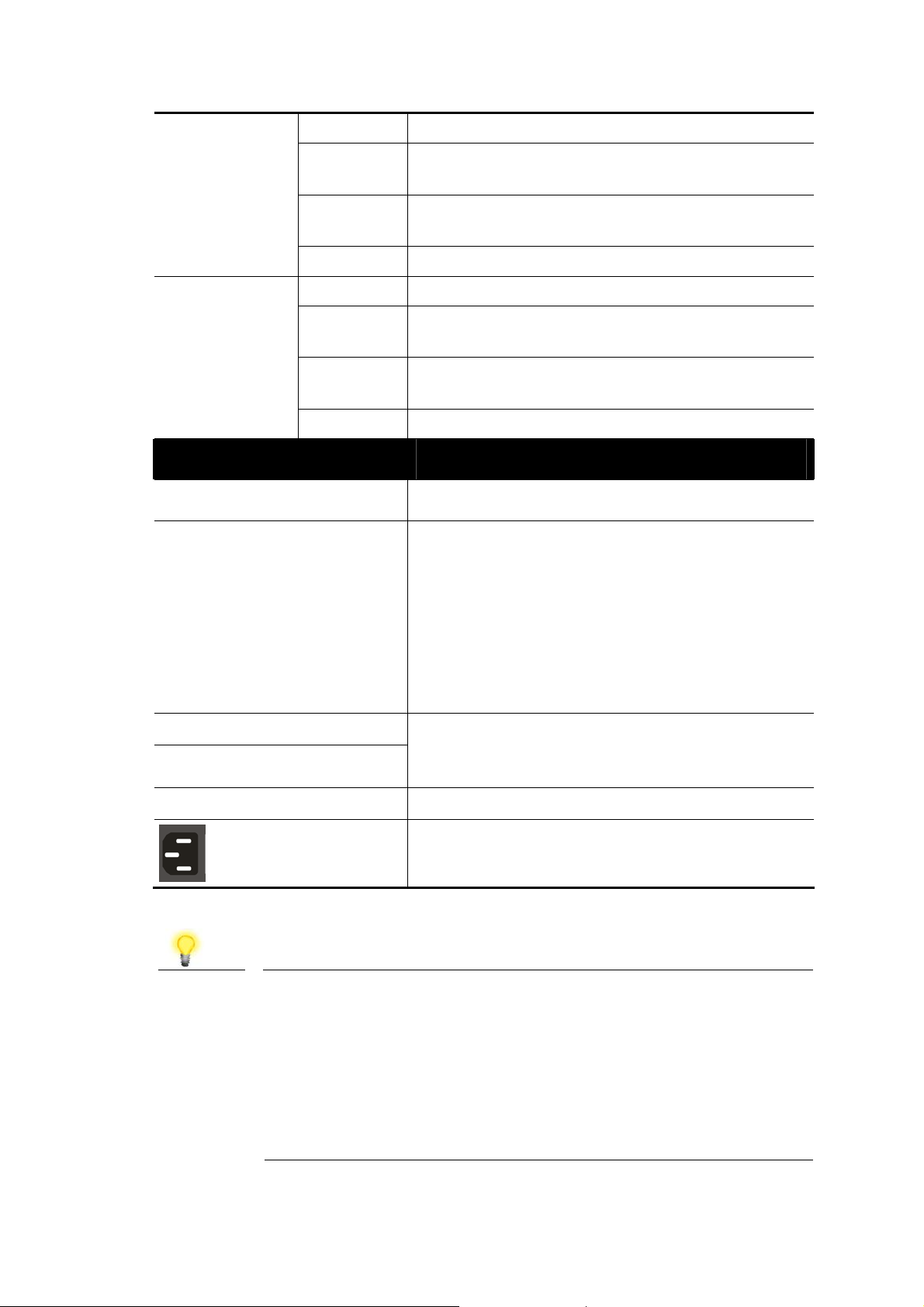
Combo for Port
9 ~ 12
(RJ 45
On (Green) The device is connected with 1000Mbps.
On
The device is connected with 10/100Mbps.
(Amber)
LNK/ACT)
Blinking The system is sending or receiving data
through the port.
Off The port is disconnected or the link is failed.
SFP LNK/ACT
On (Green) The device is connected with 1000Mbps.
On
The device is connected with 10/100Mbps.
(Amber)
Blinking The system is sending or receiving data
through the port.
Off
The port is disconnected or the link is failed.
Interface Description
Console
RST
Used to perform telnet command control.
Factory reset button.
Press it to reboot the system. (<5 seconds)
The PoE/Alert and SYS LEDs will blink too.
Press it to reset the system with factory
default settings. (5~20 seconds)
The PoE/Alert and SYS LEDs will be off if
RST button is pressed between 5 seconds
and 10 seconds.
RJ 45 LNK/ACT Port 1 ~ 8
PoE for Port 1 ~ 8
SFP LNK/ACT Port 9 ~ 12
Note
The following limitation is suitable for VigorSwitch P2121
Power Output --
IEEE 802.3af Max. 15.4W Output Supported
IEEE 802.3at Max. 30W Output Supported
PoE Power Budget –-
140 Watts (Max)
Port 1 to Port 8 can be used for Ethernet
connection and PoE connection, depending on
the device connected
.
Port 9 to Port 12 are used for fiber connection.
Power inlet for AC input (100~240V/AC,
50/60Hz).
3
Page 11
Haarrdd
H
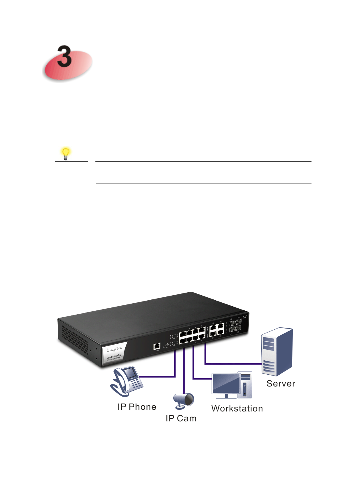
This section will guide you to install the switch through hardware connection and
configure the switch’s settings through web browser.
Before starting to configure the switch, you have to connect your devices
correctly.
Note
33..11 NNeettwwoorrkk CCoonnnneeccttiioonn
Use a Cat. 5e twisted-pair cable to connect a PoE device to the port (1~8) of
this switch.
The switch will supply power to PoE Device over the twisted-pair cable.
Please note that Power Device must comply with IEEE 802.3af/at.
Power the device to this switch and get 54V power source through
Cat. 5e Cable.
waarree IInnssttaallllaattiioonn
w
Other PCs, servers and network devices can be connected to the switch using
a standard ‘straight through’ twisted pair cable.
(Take VigorSwitch P2121 as an example.)
4
Page 12
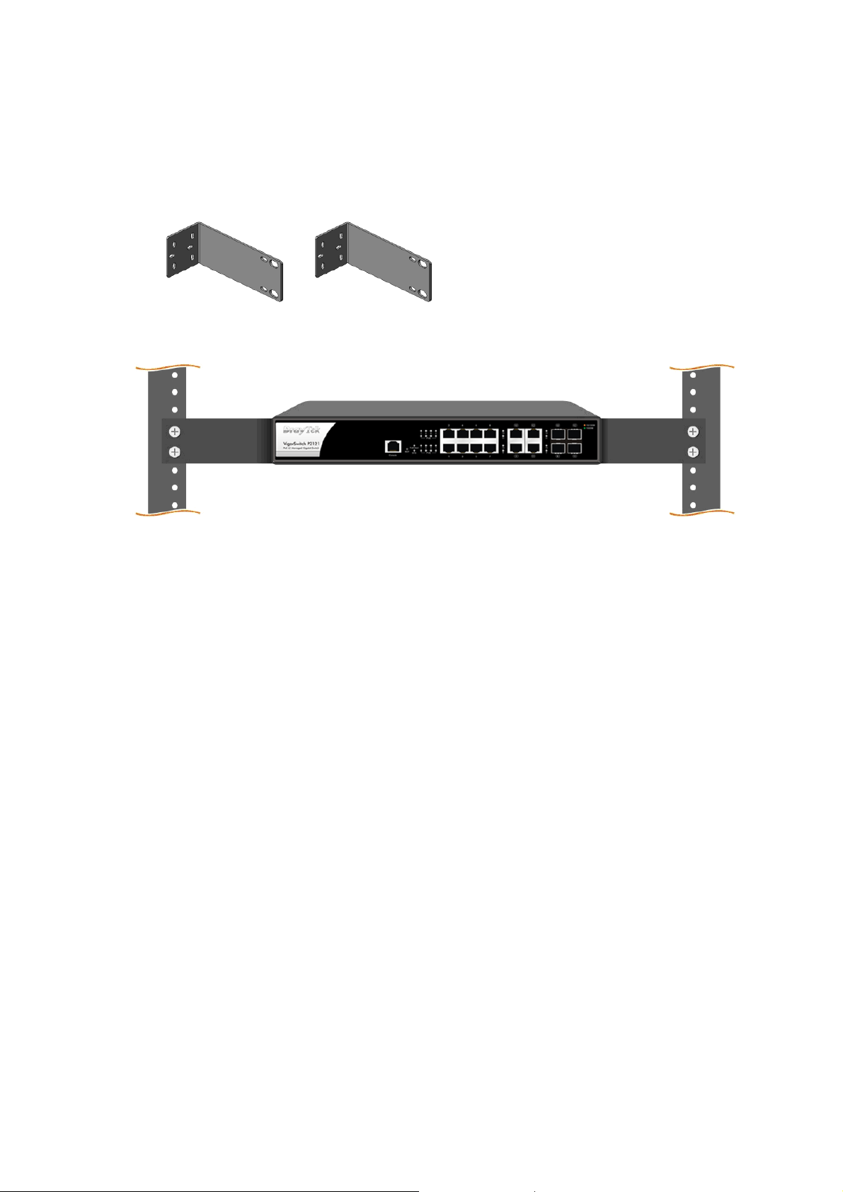
33..22 RRaacckk--MMoouunntteedd IInnssttaallllaattiioonn
The switch can be installed easily by using rack mount kit.
1. Attach the brackets to the chassis of a 19- or a 23-inch rack. The second
bracket attaches the other side of the chassis as above procedure.
2. After the bracket installation, the VigorSwitch’s chassis can be installed in a
rack by using four screws for each side of the rack.
(Take VigorSwitch P2121 as an example.)
5
Page 13
Soofftt
S
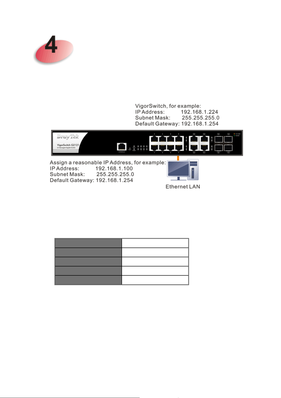
In this section, we take VigorSwitch G2121 as an example:
Before using the switch, perform the following steps:
waarree
w
Coonnffiigguurraattiioonn
C
1. Set up a physical path between the configured the switch and a PC by a
qualified UTP Cat. 5e cable with RJ-45 connector.
If a PC directly connects to the switch, you have to setup the same subnet mask for
PC and the switch.
IP Address 192.168.1.224
Subnet Mask
DHCP Client Enabled (On)
Username admin
Password admin
2. After configuring correct IP address on your PC, open your web browser and
access switch's IP address.
Default values of the managed switch are listed as follows:
255.255.255.0
6
Page 14
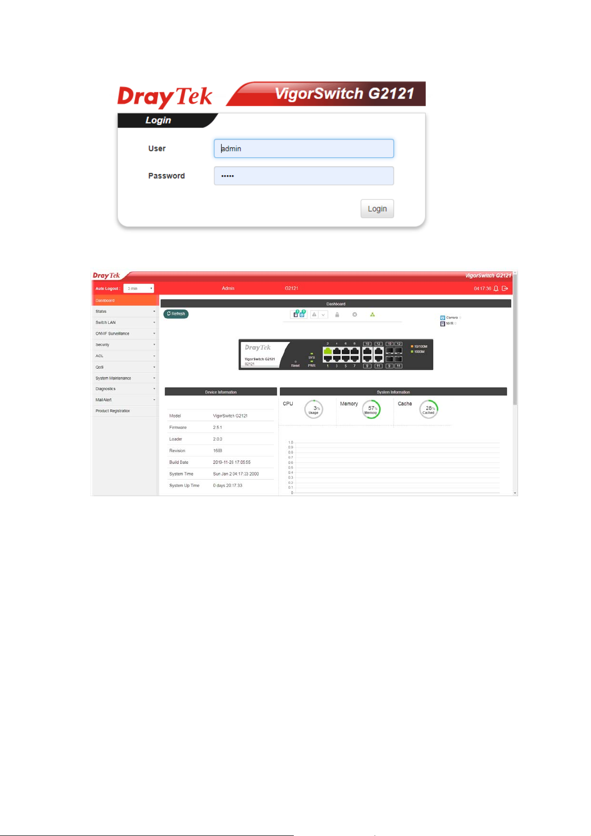
The home page of VigorSwitch will be shown as below:
7
Page 15

CCuussttoommeerr SSeerrvviiccee
If the switch cannot work correctly after trying many efforts, please contact your
dealer for further help right away. For any questions, please feel free to send
e-mail to [email protected].
GPL Notice This DrayTek product uses software partially or completely licensed under
the terms of the GNU GENERAL PUBLIC LICENSE. The author of the software
does not provide any warranty. A Limited Warranty is offered on DrayTek
products. This Limited Warranty does not cover any software applications or
programs.
To download source codes please visit:
http://gplsource.draytek.com
GNU GENERAL PUBLIC LICENSE:
https://gnu.org/licenses/gpl-2.0
Version 2, June 1991
For any question, please feel free to contact DrayTek technical support at
[email protected] for further information.
8
 Loading...