

Page 1
i
Page 2

VigorAP 912C
802.11ac Ceiling-mount Access
Point
Quick Start Guide
Version: 1.1
Firmware Version: V1.3.2
(For future update, please visit DrayTek web site)
Date: February 27, 2020
ii
Page 3

Intellectual Property Rights (IPR) Information
Copyrights
Trademarks
© All rights reserved. This publication contains information that is protected
by copyright. No part may be reproduced, transmitted, transcribed, stored in
a retrieval system, or translated into any language without written permission
from the copyright holders.
The following trademarks are used in this document:
Microsoft is a registered trademark of Microsoft Corp.
Windows, Windows 8, 10 and Explorer are trademarks of Microsoft Corp.
Apple and Mac OS are registered trademarks of Apple Inc.
Other products may be trademarks or registered trademarks of their
respective manufacturers.
Safety Instructions and Approval
Safety
Instructions
Read the installation guide thoroughly before you set up the device.
The device is a complicated electron ic unit that may be repair ed only be
authorized and qualified personnel. Do not try to open or repair the
device yourself.
Do not place the device in a damp or humid place, e.g. a bathroom.
Do not stack the devices.
The device should be used in a sheltered area, within a temperature
range of 0 to +45 Celsius.
Do not expose the device to direct sunlight or other heat sources. The
housing and electronic components may be damaged by direct sunlight
or heat sources.
Do not deploy the cable for LAN connection outdoor to prevent
electronic shock hazards.
Keep the package out of reach of children.
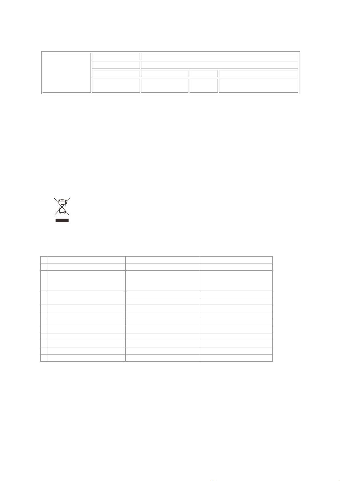
When you want to dispose of the device, please follow local regulations
on conservation of the environment.
Warranty
We warrant to the original end user (purchaser) that the device will be free
from any defects in workmanship or materials for a period of one (1) year from
the date of purchase from the dealer. Please keep your purchase receipt in a
safe place as it serves as proof of date of purchase. During the warranty
period, and upon proof of purchase, should the product have indications of
failure due to faulty workmanship and/or materials, we will, at our discretion,
repair or replace the defective products or components, without charge for
either parts or labor, to whatever extent we deem necessary tore-store the
product to proper operating condition. Any replacement will consist of a new
or re-manufactured functionally equivalent product of equal value, and will
be offered solely at our discretion. This warranty will not apply if the produ ct
is modified, misused, tampered with, damaged by an act of God, or subjected
to abnormal working conditions. The warranty does not cover the bundled or
licensed software of other vendors. Defects which do not significantly affect
the usability of the product will not be covered by the warranty. We reserve
the right to revise the manual and online documentation and to make changes
from time to time in the contents hereof without obligation to notify any
person of such revision or changes.
i
Page 4
Declaration of Conformity
Hereby, DrayTek Corporation declares that the radio equipment type VigorAP 912C is in compliance
with Directive 2014/53/EU.
The full text of the EU declaration of conformity is available at the following internet address:
http://www.draytek.com.tw/ftp/VigorAP 912C/Document/CE/
Manufacturer: DrayTek Corp.
Address: No. 26, Fu Shing Road, HuKou Township, HsinChu Industrial Park, Hsin-Chu County,
Taiwan 303
Product: VigorAP 912C
Frequency Information for Europe area:
2.4G WLAN 2412MHz - 2472 MHz, max. TX power: 19.98dBm *1
5G WLAN 5160MHz - 5340 MHz, max. TX power: 22 dBm ;
5480MHz - 5720 MHz, max. TX power: 29 dBm
(*1: for 2.4G WLAN model; *2: for 5G WLAN model)
This product is designed for 2.4GHz and 5GHz WLAN network throughout the EC region.
Regulatory Information
Federal Communication Commission Interference Statement
This equipment has been tested and found to comply with the limits for a Class B digital device,
pursuant to Part 15 of the FCC Rules. These limits are designed to provide reasonable protection
against harmful interference in a residential installation. This equipment generates, uses and can
radiate radio frequency energy and, if not installed and used in accordance with the instructions, may
cause harmful interference to radio communications. However, there is no guarantee that
interference will not occur in a particular installation. If this equipment does cause harmful
interference to radio or television reception, which can be determined by turning the equipment off
and on, the user is encouraged to try to correct the interference by one of the following measures:
Reorient or relocate the receiving antenna.
Increase the separation between the equipment and receiver.
Connect the equipment into an outlet on a circuit different from that to which the receiver
is connected.
Consult the dealer or an experienced radio/TV technician for help.
This device complies with Part 15 of the FCC Rules. Operation is subject to the following two
conditions:
(1) This device may not cause harmful interference, and
(2) This device may accept any interference received, including interference that may cause
undesired operation.
ii
Page 5
Company name ABP International Inc.
USA Local
Representative
Caution
Any changes or modifications not expressly approved by the grantee of this device could void the
user's authority to operate the equipment.
Any changes or modifications not expressly approved by the party responsible for compl iance could
void the user's authority to operate this equipment.
This transmitter must not be co-located or operating in conjunction with any other antenna or
transmitter.
Radiation Exposure Statement: This equipment complies with FCC radiation exposure limits set forth
for an uncontrolled environment. This equipment should be installed and operated with minimum
distance 20cm between the radiator & your body.
Address 13988 Diplomat Drive Suite 180 Dallas TX 75234
ZIP Code 75234 E-mail rmesser@abptech.com
Contact Person Mr. Robert
Messer
Tel. 19728311600
Operations in the 5.15-5.25GHz band are restricted to indoor usage only.
More update, please visit www.draytek.com.
* The external power supply used for each product will be model dependent.
1 2
A Manufacturer DVE DVE
No.5, Baogao Rd, Xindian
B Address
C Model identifier
D Input voltage 100~240V 100~240V
Input AC frequency 50/60Hz 50/60Hz
E
Output voltage DC 12.0V 12.0V
F Output current 1.0A 1.5A
G Output power 12.0W 18.0W
H Average active efficiency 83.3% 85.5%
I Efficiency at low load 10% 80.8% 83.7%
J No-load power consumption 0.06W 0.07W
Dist, New Taipei City
(23144), Taiwan
DSA-12PF09-12 FUK DSA-18PFR-12 FUK
DSA-12PF09-12 FEU DSA-18PFR-12 FEU
No.5, Baogao Rd, Xindian
Dist, New Taipei City
(23144), Taiwan
* External power supply (Power Adapter) information. For more update, please visit www.draytek.com.
iii
Page 6

TTaabbllee ooff CCoonntteennttss
1. Package Content .................................................................................................. 1
2. Panel Explanation................................................................................................. 2
3. Installation............................................................................................................. 3
3.1 Ceiling-mount Installation (Wooden Ceiling).............................................................................. 3
3.2 Ceiling-mount Installation (Plasterboard Ceiling)....................................................................... 4
3.3 Suspended Ceiling (Lightweight Steel Frame) Installation.........................................................5
3.4 Wall-Mounted Installation........................................................................................................... 7
4. Connection and Configuration............................................................................ 8
4.1 Notifications for Hardware Connection.......................................................................................8
4.2 Connect to a Vigor Router using AP Management.................................................................... 9
4.3 Web Configurations.................................................................................................................. 10
Connected As a Mesh Node (in Mesh Network).................................................................. 10
Connected As an Access Point............................................................................................ 10
5. Customer Service............................................................................................... 13
Be a Registered Owner.................................................................................................................. 13
Firmware & Tools Updates............................................................................................................. 13
iv
Page 7

11.. PPaacckkaaggee CCoonntteenntt
Take a look at the package content. If there is anything missed or damaged,
please contact DrayTek or dealer immediately.
VigorAP 912C Main Unit Ceiling mount bracket & Quick Start
Guide
T-Rail Mounting Kits
(Used for suspended ceiling)
Fixings and Screws
(for ceiling mounting)
RJ-45 Cable (Ethernet) Screw set (for wall mounting)
The type of the power adapter depends on the country that the AP will be
installed:
UK-type Power Adapter
EU-type Power Adapter
USA/Taiwan-type Power Adapter
AU/NZ-type Power Adapter
The maximum power consumption is 10 Watt.
1
Page 8

22.. PPaanneell EExxppllaannaattiioonn
LED Factory
Reset
Ethernet Port
Power Jack (DC IN)
LED Status Explanation
Blue LED
On The system is in boot-loader mode.
Off The system is not ready or fails.
Blinking The system is in AP mode and work normally.
Green LED Blinking The system is in Mesh mode or Range Extender mode
and works normally.
Orange LED Blinking The system is in TFTP mode.
Off Off VigorAP is turned off or not functioning.
Interface Explanation
Ethernet Port Connects to LAN or router.
Supports PoE power & Gigabit (1000BaseT).
Power Jack (DC IN) Connecter for a power adapter.
Hole Explanation
Factory Reset Restores the unit back to factory default settings.
To use, insert a small item such as an unbent
paperclip into the hole. You will feel the button
inside depress gently. Hold it for 5 seconds.
The VigorAP will restart with the factory default
configuration and the LED will blink blue.
Note
For the sake of security, make the accessory kit away from
children.
Remove the protective film from the access point before use
to ensure ventilation.
2
Page 9

33.. IInnssttaallllaattiioonn
VigorAP can be installed under certain locations: wooden ceiling, plasterboard
ceilings, light-weighted steel frame and wall.
33..11 CCeeiilliinngg--mmoouunntt IInnssttaallllaattiioonn ((WWooooddeenn CCeeiilliinngg))
1. Place the bracket under the wooden ceiling and fasten two screws firmly (as
shown in Figure below, Step 1).
2. When the bracket is in place, fasten two screws firmly (as shown in Figure
below, Step 2) on the bottom of VigorAP.
3. Make the device just below the bracket. Put the screws installed in Step 2 on
the holes of the bracket (as shown in Figure below, Step 3).
4. Gently rotate the device to make screws slide into the notches of the
bracket and move forward till it is firmly fixed.
Bracket
Step 3
Step 1
Step 2
3
Page 10

33..22 CCeeiilliinngg--mmoouunntt IInnssttaallllaattiioonn ((PPllaasstteerrbbooaarrdd CCeeiilliin
1. Place the bracket under the plasterboard ceiling and fasten two turnbuckles
firmly (as shown in Figure below, Step 1).
2. Make the screws pass through the bracket and insert into the turnbuckles (as
shown in Figure below, Step 2). Fasten them to offer more powerful
supporting force.
3. When the bracket is in place, fasten two screws firmly (as shown in Figure
below, Step 3) on the bottom of VigorAP.
4. Make the device just below the bracket. Put the screws installed in Step 3 on
the screw holes of the bracket (as shown in Figure below, Step 4).
5. Gently rotate the device to make screws slide into the notches of the
bracket and move forward till it is firmly fixed.
Step 1
ngg))
Bracket
Step 4
Step 2
Step 3
4
Page 11

33..33 SSuussppeennddeedd CCeeiilliinngg ((LLiigghhttwweeiigghhtt SStteeeell FFrraammee))
sttaallllaattiioonn
IInns
You cannot screw into ceiling tiles as they are weak and not suitable for bearing
loads. Your VigorAP is supplied with mounts (T-Rail brackets) which attach
directly to the metal grid (‘T-Rail’) of your suspended ceiling.
1. Choose one set of T-Rail mounting kits from the bundled package.
2. Put the T-Rail brackets on the holes of the bottom side of the device. Fasten
them with suitable screws.
T-Rail Bracket
T-Rail Bracket
3. If a larger gap is required between the ceiling and the VigorAP, use the
extension pieces to extend the height of the brackets.
Extension Piece
Extension Piece
5
Page 12

4. Attach the T-Rail brackets to the ceiling frame.
Note
Warning: The screw set shown below is for wall mounting only.
Do not use such set for ceiling mounting due to the danger of
falling.
6
Page 13

33..44 WWaallll--MMoouunntteedd IInnssttaallllaattiioonn
For wall-mounting, the VigorAP has keyhole type mounting slots on the underside.
You can fit the AP at any axis (i.e. 12, 3, 6 or 9 O’Clock) to allow for cable entry
from the most convenient location if you are using side entry – note the position
of the side entry cable cutout.
1. A template is provided on the VigorAP’s packaging box to enable you to
space the screws correctly on the wall.
2. Place the template on the wall and drill the holes according to the
recommended instruction.
3. Fit screws into the wall using the appropriate type of wall plug (as shown in
the ceiling section) but do not use the ceiling bracket – the VigorAP hangs
directly onto the screws.
Wall (wooden, concrete,
plasterboard or others)
7
Page 14

44.. CCoonnnneeccttiioonn aanndd CCoonnffiigguurraattiioonn
44..11 NNoottiiffiiccaattiioonnss ffoorr HHaarrddwwaarree CCoonnnneeccttiioonn
If required, remove the protective cap of VigorAP to create extra space
for the cables to pass through.
Connect VigorAP to Vigor router (via LAN port) with Ethernet cable.
Connect VigorAP to PoE switch (via LAN port) with Ethernet cable. For
connecting with PoE switch, do not connect the power adapter. VigorAP
will get the power from the switch directly.
8
Page 15

44..22 CCoonnnneecctt ttoo aa VViiggoorr RRoouutteerr uussiinngg AAPP MMaannaaggeemmeenntt
Your VigorAP can be used with Vigor routers which support AP management (such
as the Vigor2862 or Vigor2926 series). AP Management enables you to monitor
and manage multiple DrayTek APs from a single interface.
1. Connect one end of the power adapter to power port of VigorAP, and the
other side into a wall outlet.
2. Access into the web user interface of Vigor router. Here we take Vigor2862
as an example. Open Central Management>>AP>>Status.
3. Locate VigorAP 912C. Click the IP address assigned by Vigor router to access
into web user interface of VigorAP 912C.
4. After typing username and password (admin/admin), the main screen will be
displayed.
9
Page 16

44..33 WWeebb CCoonnffiigguurraattiioonnss
This section will guide you to install the AP and make configuration for VigorAP.
CCoonnnneecctteedd AAss aa MMeesshh NNooddee ((iinn MMeesshh NNeettwwoorrkk))
Install VigorAP on to the ceiling.
As a mesh node, settings related to VigorAP 912C must be configured
by a remote Mesh Root (e.g., VigorAP 903) within the mesh network.
The user must detect VigorAP 912C via a Mesh Root to add it as a mesh
node.
CCoonnnneecctteedd AAss aann AAcccceessss PPooiinntt
As an access point, VigorAP 912C must be connected to a router and configured
in AP (Access Point) / Range Extender mode.
Install VigorAP on to the ceiling.
Use a twisted-pair cable with RJ-45 plugs at both ends, and plug into
Ethernet device (e.g., Vigor router) and Ethernet port of VigorAP.
10
Page 17

There are two methods to configure VigorAP.
Method 1:
(a) First, open a web browser on your PC and type https://192.168.1.2. A
pop-up window will open to ask for username and password.
Note
You may either simply set up your computer to get IP
dynamically from the router or set up the IP address of the
computer to be in the same subnet as the IP address of
VigorAP 912C.
If there is no DHCP server on the network, then VigorAP
912C will have an IP address of 192.168.1.2.
If there is DHCP available on the network, then VigorAP
912C will receive its IP address via the DHCP server.
If you connect to VigorAP by wireless LAN, you could try
to access the web user interface through
http://vigorap.com.
(b) After clicking Login, Quick Start Wizard for configuring wireless
settings will appear as follows.
11
Page 18

(c) Follow the on-screen steps to finish the network connection.
Method 2:
(a) Use a mobile phone to scan the QR code named with DrayTek Wirel ess
App to download DrayTek Wireless APP.
(b) After downloading, run the APP.
(c) Click Quick Start Wizard. Next, scan the QR code named with Connect
SSID. Later, click Connect to access into the APP user interface of
VigorAP 912C to set the device in AP or Range Extender mode.
12
Page 19

55.. CCuussttoommeerr SSeerrvviiccee
If the device cannot work correctly after trying many efforts, please contact
your dealer/DrayTek for further help right away. For any questions, please feel
free to send e-mail to “support@draytek.com”.
BBee aa RReeggiisstteerreedd OOwwnneerr
Web registration is preferred. You can register your Vigor router via
http://www.draytek.com.
FFiirrmmwwaarree && TToooollss UUppddaatteess
Due to the continuous evolution of DrayTek technology, all routers will be
regularly upgraded. Please consult the DrayTek web site for more information on
newest firmware, tools and documents.
http://www.draytek.com
GPL Notice This DrayTek product uses software partially or completely licensed
under the terms of the GNU GENERAL PUBLIC LICENSE. The author of
the software does not provide any warranty. A Limited Warranty is
offered on DrayTek products. This Limited Warranty does not cover
any software applications or programs.
To download source codes please visit:
http://gplsource.draytek.com
GNU GENERAL PUBLIC LICENSE:
https://gnu.org/licenses/gpl-2.0
Version 2, June 1991
For any question, please feel free to contact DrayTek technical
support at support@draytek.com for further information.
13
 Loading...