

Page 1
i
VigorAP 910C User’s Guide
Page 2

VViiggoorrAAPP 991100CC
880022..1111aacc CCeeiilliinngg--m
UUsseerr’’ss GGuuiiddee
moouunntt AAcccceessss PPooiinntt
Version: 2.5
Firmware Version: V1.2.8
(For future update, please visit DrayTek web site)
Date: May 03, 2019
VigorAP 910C User’s Guide
ii
Page 3

Intellectual Property Rights (IPR) Information
Copyrights
Trademarks
© All rights reserved. This publication contains information that is protected by copyright.
No part may be reproduced, transmitted, transcribed, stored in a retrieval system, or
translated into any language without written permission from the copyright holders.
The following trademarks are used in this document:
Microsoft is a registered trademark of Microsoft Corp.
Windows, Windows 95, 98, Me, NT, 2000, XP, Vista, 7 and Explorer are trademarks of
Microsoft Corp.
Apple and Mac OS are registered trademarks of Apple Inc.
Other products may be trademarks or registered trademarks of their respective
manufacturers.
Safety Instructions and Approval
Safety
Instructions
Read the user guide thoroughly before you set up the device.
The access point is a complicated electronic unit that may be repaired only be
authorized and qualified personnel. Do not try to open or repair the modem yourself.
Do not place the access point in a damp or humid place, e.g. a bathroom.
The modem should be used in a sheltered area, within a temperature range of +5 to +40
Celsius.
Do not expose the access point to direct sunlight or other heat sources. The housing and
electronic components may be damaged by direct sunlight or heat sources.
Do not deploy the cable for LAN connection outdoor to prevent electronic shock
hazards.
Keep the package out of reach of children.
When you want to dispose of the access point, please follow local regulations on
conservation of the environment.
Warranty
Be a Registered
Owner
Firmware & Tools
Updates
We warrant to the original end user (purchaser) that the access point will be free from any
defects in workmanship or materials for a period of one (1) year from the date of purchase
from the dealer. Please keep your purchase receipt in a safe place as it serves as proof of date
of purchase. During the warranty period, and upon proof of pur ch a se, should the product
have indications of failure due to faulty workmanship and/or materials, we will, at our
discretion, repair or replace the defective products or components, without charge for either
parts or labor, to whatever extent we deem necessary tore-store the product to proper
operating condition. Any replacement will consist of a new or re-manufactured functionally
equivalent product of equal value, and will be offered solely at our discretion. This warranty
will not apply if the product is modified, misused, tampered with, damaged by an act of God,
or subjected to abnormal working conditions. The warranty does not cover the bundled or
licensed software of other vendors. Defects which do not significantly affect the usability of
the product will not be covered by the warranty. We reserve the right to revise the manual
and online documentation and to make changes from time to time in the contents hereof
without obligation to notify any perso n of such revi si o n o r chan ges.
Web registration is preferred. You can register your Vigor AP via http://www.draytek.com.
Due to the continuous evolution of DrayTek technology, all access points will be regularly
upgraded. Please consult the DrayTek web site for more information on newest firmware,
tools and documents.
http://www.draytek.com
iii
VigorAP 910C User’s Guide
Page 4

FCC RF Radiation Exposure Statement
1. This Transmitter must not be co-located or operating in conjunction with any other antenna or transmitter.
2. This equipment complies with FCC RF radiation exposure limits set forth for an uncontrolled environment.
This equipment should be installed and operated with a minimum distance of 20 centimeters between the
radiator and your body.
GPL Notice
This DrayTek product uses software partial ly or completely licensed under the terms of the GNU GENERAL
PUBLIC LICENSE. The author of the software does not provide any warranty. A Limited Warranty is offered on
DrayTek products. This Limited Warranty does not cover any software applications or programs.
To download source codes please visit:
http://gplsource.draytek.com
GNU GENERAL PUBLIC LICENSE:
https://gnu.org/licenses/gpl-2.0
Version 2, June 1991
For any question, please feel free to contact DrayTek technical support at support@draytek.com for further
information.
VigorAP 910C User’s Guide
iv
Page 5

TTaabbllee ooff CCoonntteennttss
Introduction .................................................................................................1
1.1 Introduction ............................................................................................................................. 1
1.2 LED Indicators and Connectors.............................................................................................. 3
1.3 Hardware Installation .............................................................................................................. 4
1.3.1 Ceiling-mount Installation (Wooden Ceiling) .................................................................... 4
1.3.2 Ceiling-mount Installation (Plasterboard Ceiling)............................................................. 5
1.3.3 Suspended Ceiling (Lightweight Steel Frame) Installation............................................... 6
1.3.4 Wall Mounting Installation................................................................................................. 8
1.4 Notifications for Hardware Connection ................................................................................... 9
1.5 Connect to a Vigor Router using AP Management............................................................... 10
1.6 Connect to a Vigor Router without AP Management.............................................................11
1.7 Connect without a DrayTek Router/LAN............................................................................... 12
1.8 Connecting to PC Directly..................................................................................................... 13
Network Configuration..............................................................................15
2.1 Windows 7 IP Address Setup................................................................................................ 15
2.2 Windows 2000 IP Address Setup.......................................................................................... 17
2.3 Windows XP IP Address Setup............................................................................................. 18
2.4 Windows Vista IP Address Setup.......................................................................................... 19
2.5 Accessing to Web User Interface.......................................................................................... 20
2.6 Changing Password.............................................................................................................. 21
2.7 Quick Start Wizard................................................................................................................ 22
2.7.1 Configuring Wireless Settings – General........................................................................ 22
2.7.2 Configuring 2.4GHz Wireless Settings Based on the Operation Mode.......................... 23
2.7.3 Configuring 5GHz Wireless Settings Based on the Operation Mode............................. 30
2.7.4 Finishing the Wireless Settings Wizard.......................................................................... 35
2.8 Online St atus......................................................................................................................... 36
Advanced Configuration.................................................................................37
3.1 Operation Mode .................................................................................................................... 38
3.2 LAN .......................................................................................................................................39
3.2.1 General Setup................................................................................................................. 39
3.2.2 Web Portal...................................................................................................................... 43
3.3 Central AP Management.......................................................................................................46
v
VigorAP 910C User’s Guide
Page 6

3.3.1 General Setup................................................................................................................. 46
3.3.2 APM Log......................................................................................................................... 47
3.3.3 Function Support List...................................................................................................... 47
3.3.4 Overload Management................................................................................................... 48
3.3.5 Status of Settings............................................................................................................ 49
3.4 General Concepts for Wireless LAN (2.4GHz/5GHz)........................................................... 50
3.5 Wireless LAN (2.4GHz) Settings for AP Mode...................................................................... 53
3.5.1 General Setup................................................................................................................. 53
3.5.2 Security........................................................................................................................... 55
3.5.3 Access Control................................................................................................................ 58
3.5.4 WPS................................................................................................................................ 59
3.5.5 Advanced Setting............................................................................................................ 60
3.5.6 AP Discovery.................................................................................................................. 62
3.5.7 WMM Configuration........................................................................................................ 64
3.5.8 Bandwidth Management................................................................................................. 66
3.5.9 Airtime Fairness.............................................................................................................. 67
3.5.10 Station Control.............................................................................................................. 69
3.5.11 Roaming ....................................................................................................................... 70
3.5.12 Band Steering............................................................................................................... 72
3.5.13 Station List.................................................................................................................... 77
3.6 Wireless LAN (2.4GHz) Settings for S tation-Infrastructure Mode.......................................... 79
3.6.1 General Setup................................................................................................................. 79
3.6.2 Site Survey ..................................................................................................................... 84
3.6.3 Statistics.......................................................................................................................... 85
3.6.4 WPS (Wi-Fi Protected Setup)......................................................................................... 85
3.7 Wireless LAN (2.4GHz) Settings for AP Bridge-Point to Point/AP Bridge-Point to Multi-Point
Mode ...........................................................................................................................................87
3.7.1 General Setup................................................................................................................. 87
3.7.2 Advanced Setting............................................................................................................ 90
3.7.3 AP Discovery.................................................................................................................. 93
3.7.4 WDS AP Status .............................................................................................................. 94
3.8 Wireless LAN (2.4GHz) Settings for AP Bridge-WDS Mode................................................. 95
3.8.1 General Setup................................................................................................................. 95
3.8.2 Security........................................................................................................................... 98
3.8.3 Access Control.............................................................................................................. 101
3.8.4 WPS.............................................................................................................................. 102
3.8.5 Advanced Setting.......................................................................................................... 103
3.8.6 AP Discovery................................................................................................................ 106
3.8.7 WDS AP Status ............................................................................................................ 107
3.8.8 WMM Configuration...................................................................................................... 108
3.8.9 Bandwidth Management............................................................................................... 110
3.8.10 Airtime Fairness.......................................................................................................... 111
3.8.11 Station Control............................................................................................................ 113
3.8.12 Roaming ..................................................................................................................... 114
3.8.13 Band Steering............................................................................................................. 116
3.8.14 Station List.................................................................................................................. 121
3.9 Wireless LAN (2.4GHz) Settings for Universal Repeater Mode......................................... 123
3.9.1 General Setup............................................................................................................... 123
3.9.2 Security......................................................................................................................... 125
3.9.3 Access Control.............................................................................................................. 128
3.9.4 WPS.............................................................................................................................. 129
3.9.5 Advanced Setting.......................................................................................................... 130
3.9.6 AP Discovery................................................................................................................ 133
3.9.7 Universal Repeater....................................................................................................... 134
VigorAP 910C User’s Guide
vi
Page 7

3.9.8 WMM Configuration...................................................................................................... 137
3.9.9 Bandwidth Management............................................................................................... 139
3.9.10 Airtime Fairness.......................................................................................................... 140
3.9.11 Station Control............................................................................................................ 142
3.9.12 Roaming ..................................................................................................................... 143
3.9.13 Band Steering............................................................................................................. 145
3.9.14 Station List.................................................................................................................. 150
3.10 Wireless LAN (5GHz) Settings for AP Mode..................................................................... 152
3.10.1 General Setup............................................................................................................. 152
3.10.2 Security....................................................................................................................... 154
3.10.3 Access Control............................................................................................................ 157
3.10.4 WPS............................................................................................................................ 158
3.10.5 Advanced Setting........................................................................................................ 159
3.10.6 AP Discovery.............................................................................................................. 161
3.10.7 WMM Configuration.................................................................................................... 163
3.10.8 Bandwidth Management............................................................................................. 164
3.10.9 Airtime Fairness.......................................................................................................... 165
3.10.10 Station Control.......................................................................................................... 167
3.10.11 Roaming ................................................................................................................... 168
3.10.12 Station List................................................................................................................ 170
3.11 Wireless LAN (5GHz) Settings for AP Bridge-WDS Mode................................................ 171
3.11.1 General Setup............................................................................................................. 172
3.11.2 Security....................................................................................................................... 174
3.11.3 Access Control............................................................................................................ 177
3.11.4 WPS............................................................................................................................ 178
3.11.5 Advanced Setting........................................................................................................ 179
3.11.6 AP Discovery.............................................................................................................. 181
3.11.7 WDS AP Status .......................................................................................................... 182
3.11.8 WMM Configuration.................................................................................................... 183
3.11.9 Bandwidth Management............................................................................................. 185
3.11.10 Airtime Fairness........................................................................................................ 186
3.11.11 Station Control.......................................................................................................... 188
3.11.12 Roaming ................................................................................................................... 189
3.11.13 Station List................................................................................................................ 191
3.12 Wireless LAN (5GHz) Settings for Universal Repeater Mode ..........................................193
3.12.1 General Setup............................................................................................................. 193
3.12.2 Security....................................................................................................................... 195
3.12.3 Access Control............................................................................................................ 198
3.12.4 WPS............................................................................................................................ 199
3.12.5 Advanced Setting........................................................................................................ 200
3.12.6 AP Discovery.............................................................................................................. 202
3.12.7 Universal Repeater..................................................................................................... 204
3.12.8 WMM Configuration.................................................................................................... 206
3.12.9 Bandwidth Management............................................................................................. 208
3.12.10 Airtime Fairness........................................................................................................ 209
3.12.11 Station Control.......................................................................................................... 211
3.12.12 Roaming ................................................................................................................... 212
3.12.13 Station List................................................................................................................ 214
3.13 RADIUS Setting ................................................................................................................215
3.13.1 RADIUS Server........................................................................................................... 215
3.13.2 Certificate Management ............................................................................................. 216
3.14 Applications....................................................................................................................... 219
3.14.1 Schedule..................................................................................................................... 219
3.14.2 Apple iOS Keep Alive ................................................................................................. 221
3.14.3 Wi-Fi Auto On/Off ....................................................................................................... 222
vii
VigorAP 910C User’s Guide
Page 8

3.15 Mobile Device Management ............................................................................................. 223
3.15.1 Detection..................................................................................................................... 223
3.15.2 Policies ....................................................................................................................... 224
3.15.3 Statistics ..................................................................................................................... 225
3.16 System Maintenance......................................................................................................... 226
3.16.1 System Status............................................................................................................. 226
3.16.2 TR-069........................................................................................................................ 228
3.16.3 Administration Password............................................................................................ 230
3.16.4 Configuration Backup ................................................................................................. 231
3.16.5 Syslog/Mail Alert......................................................................................................... 233
3.16.6 Time and Date............................................................................................................ 234
3.16.7 SNMP.......................................................................................................................... 235
3.16.8 Management............................................................................................................... 236
3.16.9 Reboot System........................................................................................................... 237
3.16.10 Firmware Upgrade.................................................................................................... 237
3.17 Diagnostics........................................................................................................................ 238
3.17.1 System Log................................................................................................................. 238
3.17.2 Speed Test ................................................................................................................. 238
3.17.3 Traffic Graph............................................................................................................... 239
3.17.4 Where am I................................................................................................................. 239
3.17.5 Data Flow Monitor....................................................................................................... 240
3.17.6 WLAN (2.4GHz) Statistics ..........................................................................................241
3.17.7 WLAN(5GHz) Statistics .............................................................................................. 241
3.17.8 Station Statistics......................................................................................................... 242
3.17.9 Interference Monitor.................................................................................................... 244
3.18 Support Area..................................................................................................................... 246
Trouble Shooting.....................................................................................247
4.1 Checking If the Hardware Status Is OK or Not....................................................................247
4.2 Checking If the Network Connection Settings on Your Computer Is OK or Not ................. 248
4.3 Pinging the VigorAP from Your Computer........................................................................... 251
4.4 Backing to Factory Default Setting If Necessary ................................................................ 252
4.5 Contacting DrayTek............................................................................................................. 253
Index ...............................................................................................................................255
VigorAP 910C User’s Guide
viii
Page 9
IInnttrroodduuccttiioonn
11..11 IInnttrroodduuccttiioonn
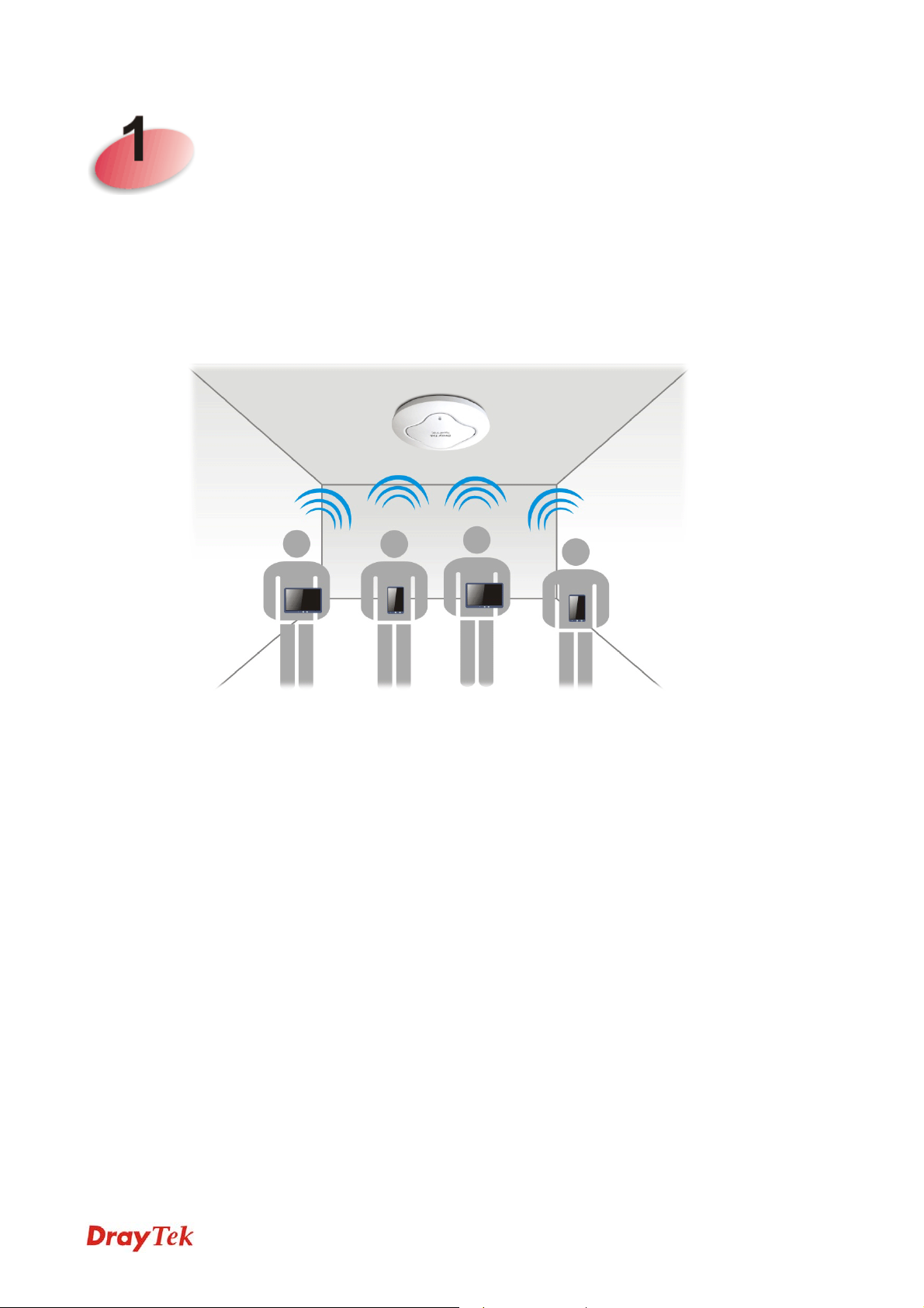
Thank you for purchasing this VigorAP 910C! With this high cost-efficiency VigorAP 910C,
computers and wireless devices which are compati ble with 802.11n can connect to existing
wired Ethernet network via this VigorAP 910C, at the speed of 300Mbps.
VigorAP 910C can operate in standalone mode for your office network or a classroom;
connected to your LAN and offering you with wireless access.
It makes high density with quality-performance be feasible for users as it is going to be
implemented with DrayTek central wireless management (AP Management) supports
configuration, firmware upgrade, status, monitoring, and load-balancing.
The Power of Ethernet (PoE) on VigorAP 910C relieves the installation of power plug. The
massive deployment of VigorAP 910C for hospitalities and school environment will be
much easier.
With the optimized antennas built-in, DrayTek VigorAP 910C ceiling-mount wireless access
point is ideal for hospitalities, small offices and small campus.
1
VigorAP 910C User’s Guide
Page 10
Easy install procedures allows any computer users to setup a network environment in very
short time - within minutes, even inexperienced users. Just follow the instructions given in
this user manual, you can complete the setup procedure and release the power of this access
point all by yourself!
VigorAP 910C User’s Guide
2
Page 11
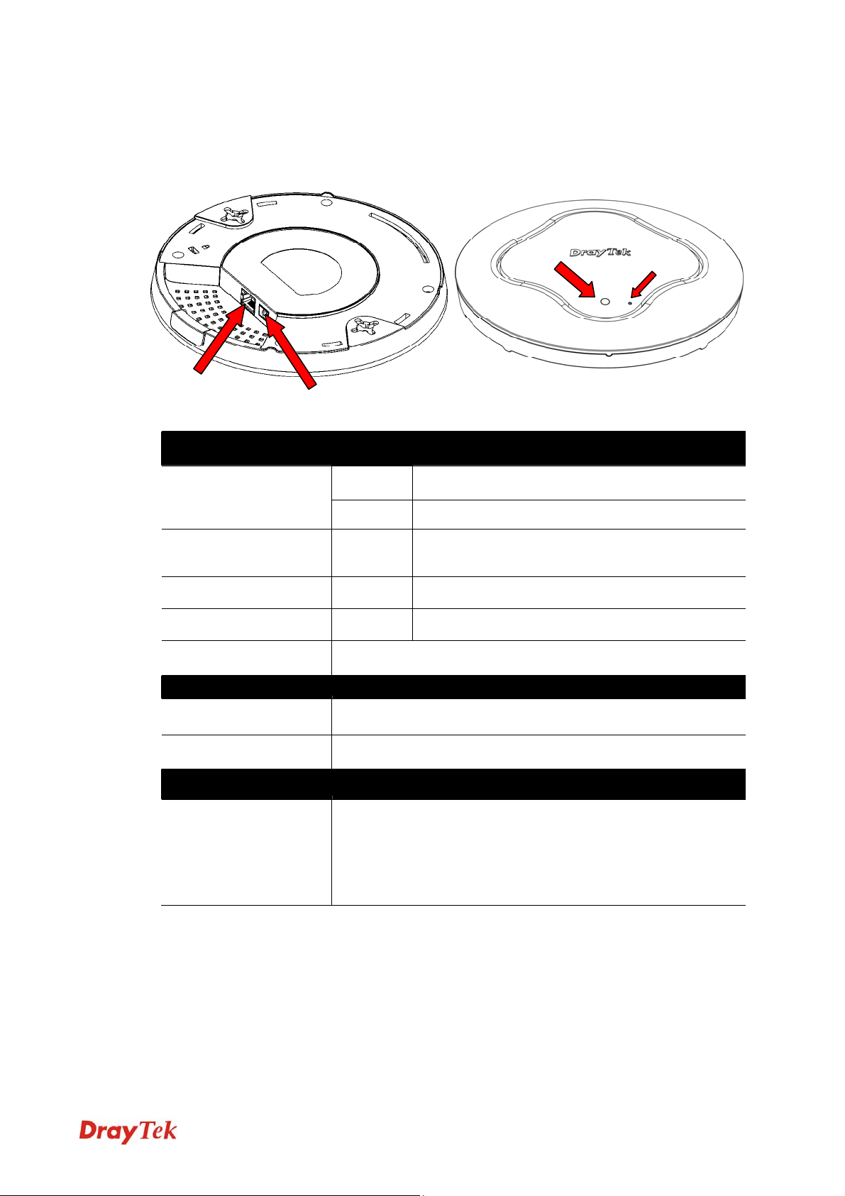
11..22 LLEEDD IInnddiiccaattoorrss aanndd CCoonnnneeccttoorrss
Before you use the Vigor modem, please get acquainted with the LED indicators and
connectors first.
Ethernet Port
LED Status Explanation
Power Jack (DC IN)
Blinking VigorAP is ready and can work normally. Blue LED
Off VigorAP is not ready or fails.
LED
Factory
Reset
Purple LED On Power adapter is plugged in and VigorAP is
initiating.
Orange LED Blinking The firmware upgrade is in process.
Off Off VigorAP is powered off.
USB Connector for a printer.
Interface Explanation
Ethernet Port Connecter for xDSL / Cable modem (Giga level) or router.
Power Jack (DC IN) Connecter for a power adapter.
Hole Explanation
Factory Reset Restore the default settings when any error occurs in VigorAP.
Usage: Use sharp article (e.g., paperclip or pin) to insert into the
hole and keep for more than 10 seconds. Then VigorAP will
restart with the factory default configuration. When purple LED
is On again, it means VigorAP has restarted and is ready to use.
3
VigorAP 910C User’s Guide
Page 12
11..33 HHaarrddwwaarree IInnssttaallllaattiioonn
VigorAP can be installed under certain locations: wooden ceiling, plasterboard ceilings,
light-weighted steel frame and wall.
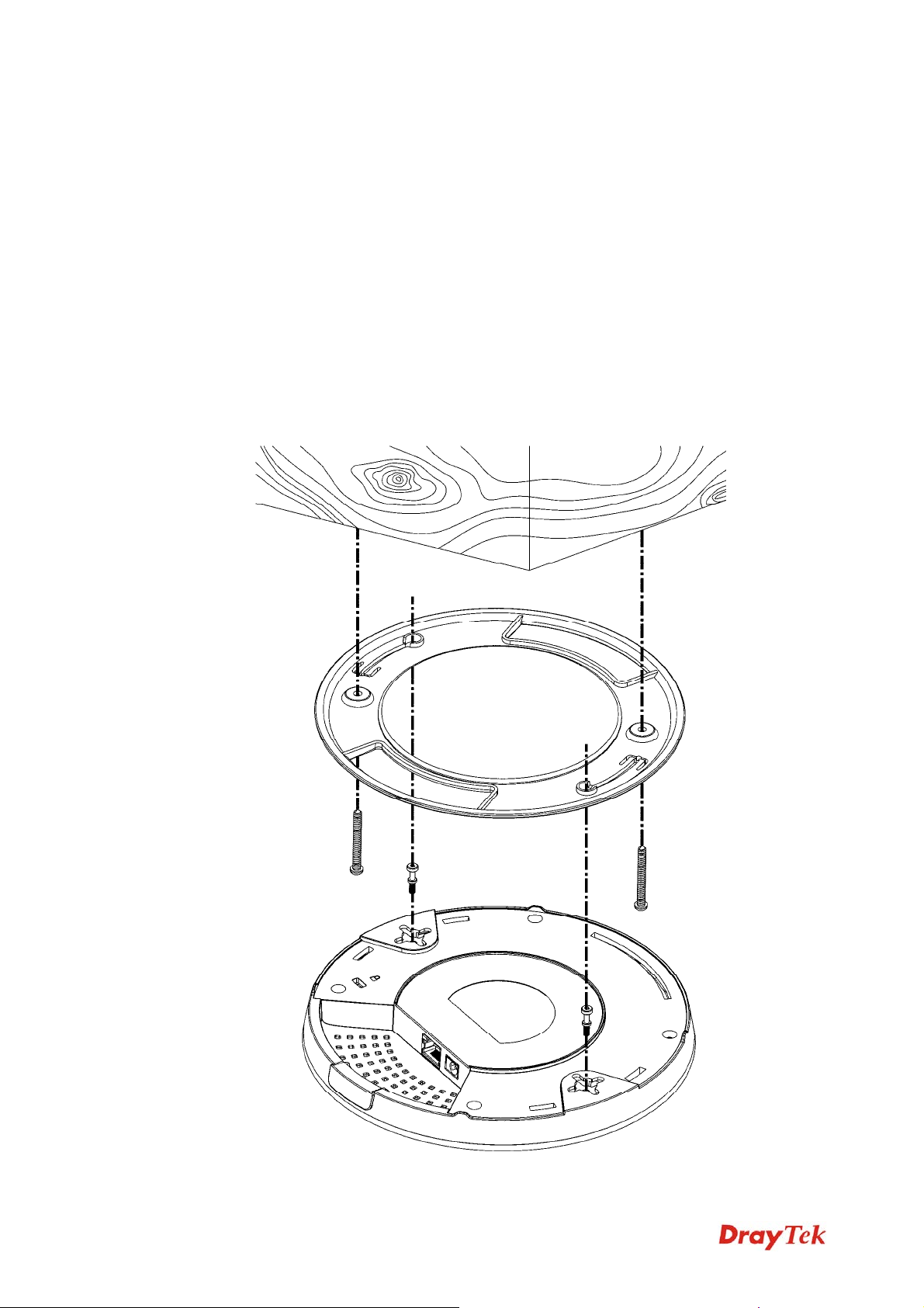
11..33..11 CCeeiilliinngg--mmoouunntt IInnssttaallllaattiioonn ((WWooooddeenn CCeeiilliinngg))
1. Place the bracket under the wooden ceiling and fasten two screws firmly (as shown in
Figure below, Step 1).
2. When the bracket is in place, fasten two screws firmly (as shown in Figure below, Step
2) on the bottom of VigorAP.
3. Make the device just below the bracket. Put the screws installed in Step 2 on the holes
of the bracket (as shown in Figure below, Step 3).
4. Gently rotate the device to make screws slide into the notches of the bracket and move
forward till it is firmly fixed.
Step 3
Bracket
Step 1
Step 2
VigorAP 910C User’s Guide
4
Page 13
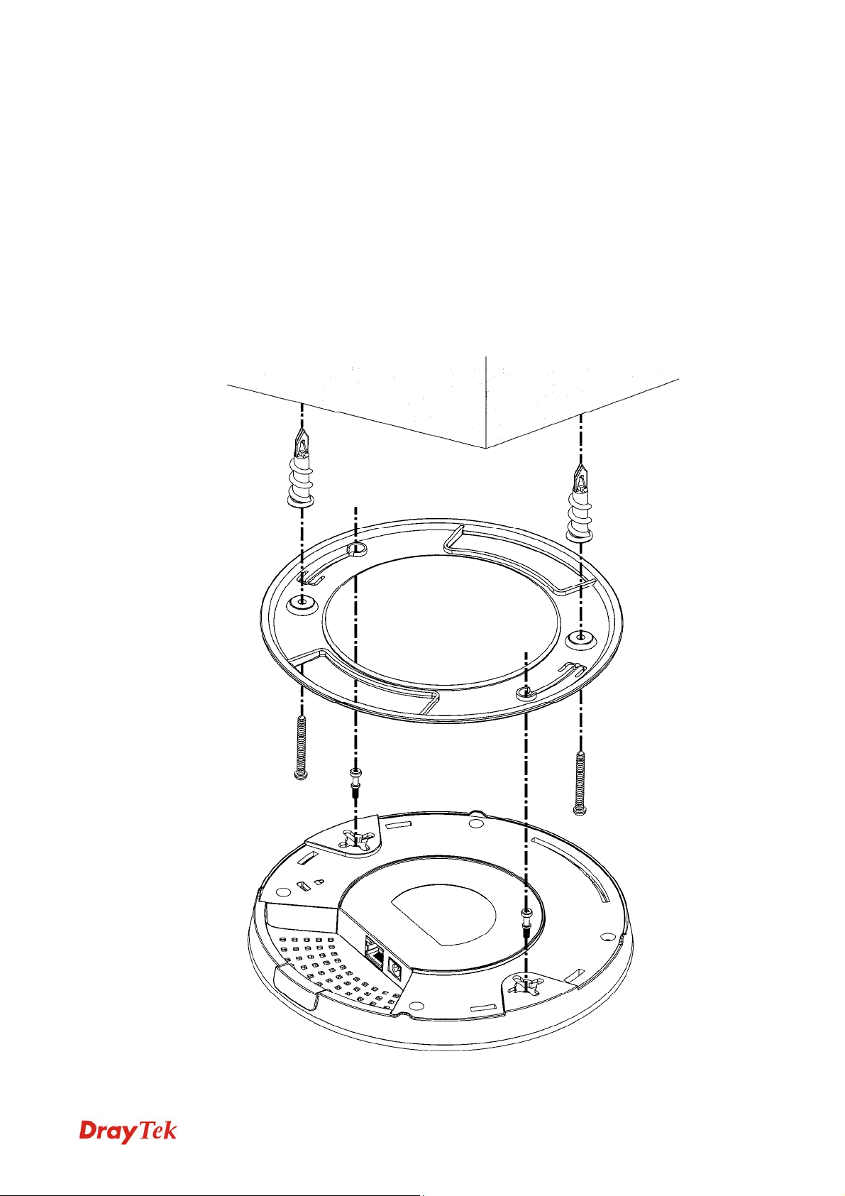
11..33..22 CCeeiilliinngg--mmoouunntt IInnssttaallllaattiioonn ((PPllaasstteerrbbooaarrdd CCeei
1. Place the bracket under the plasterboard ceiling and fasten two turnbuckles firmly (as
shown in Figure below, Step 1).
2. Make the screws pass through the bracket and insert into the turnbuckles (as shown in
Figure below, Step 2). Fasten them to offer more powerful supporting force.
3. When the bracket is in place, fasten two screws firmly (as shown in Figure below, Step
3) on the bottom of VigorAP.
4. Make the device just below the bracket. Put the screws installed in Step 3 on the screw
holes of the bracket (as shown in Figure below, Step 4).
5. Gently rotate the device to make screws slide into the notches of the bracket and move
forward till it is firmly fixed.
Step 1
illiinngg))
Step 4
Bracket
Step 2
Step 3
5
VigorAP 910C User’s Guide
Page 14
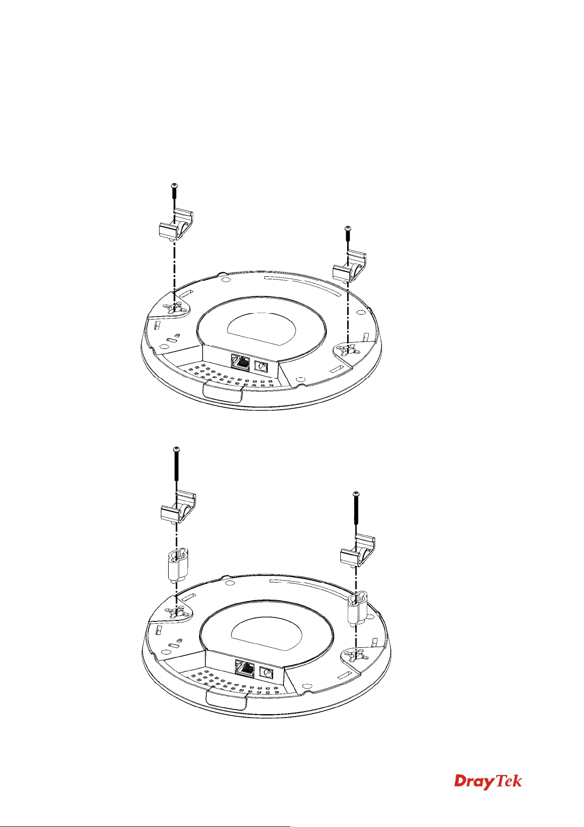
11..33..33 SSuussppeennddeedd CCeeiilliinngg ((LLiigghhttwweeiigghhtt SStteeeell FFrraammee)) I
You cannot screw into ceiling tiles as they are weak and not suitable for bearing loads. Your
VigorAP is supplied with mounts (T-Rail brackets) which attach directly to the metal grid
(‘T-Rail’) of your suspended ceiling.
1. Choose one set of T-Rail mounting kits from the bundled package.
2. Put the T-Rail brackets on the holes of the bottom side of the device. Fasten them with
suitable screws.
T-Rail Bracket
Innssttaallllaattiioonn
T-Rail Bracket
3. If a larger gap is required between the ceiling and the VigorAP, use the extension
pieces to extend the height of the brackets.
Extension Piece
Extension Piece
VigorAP 910C User’s Guide
6
Page 15
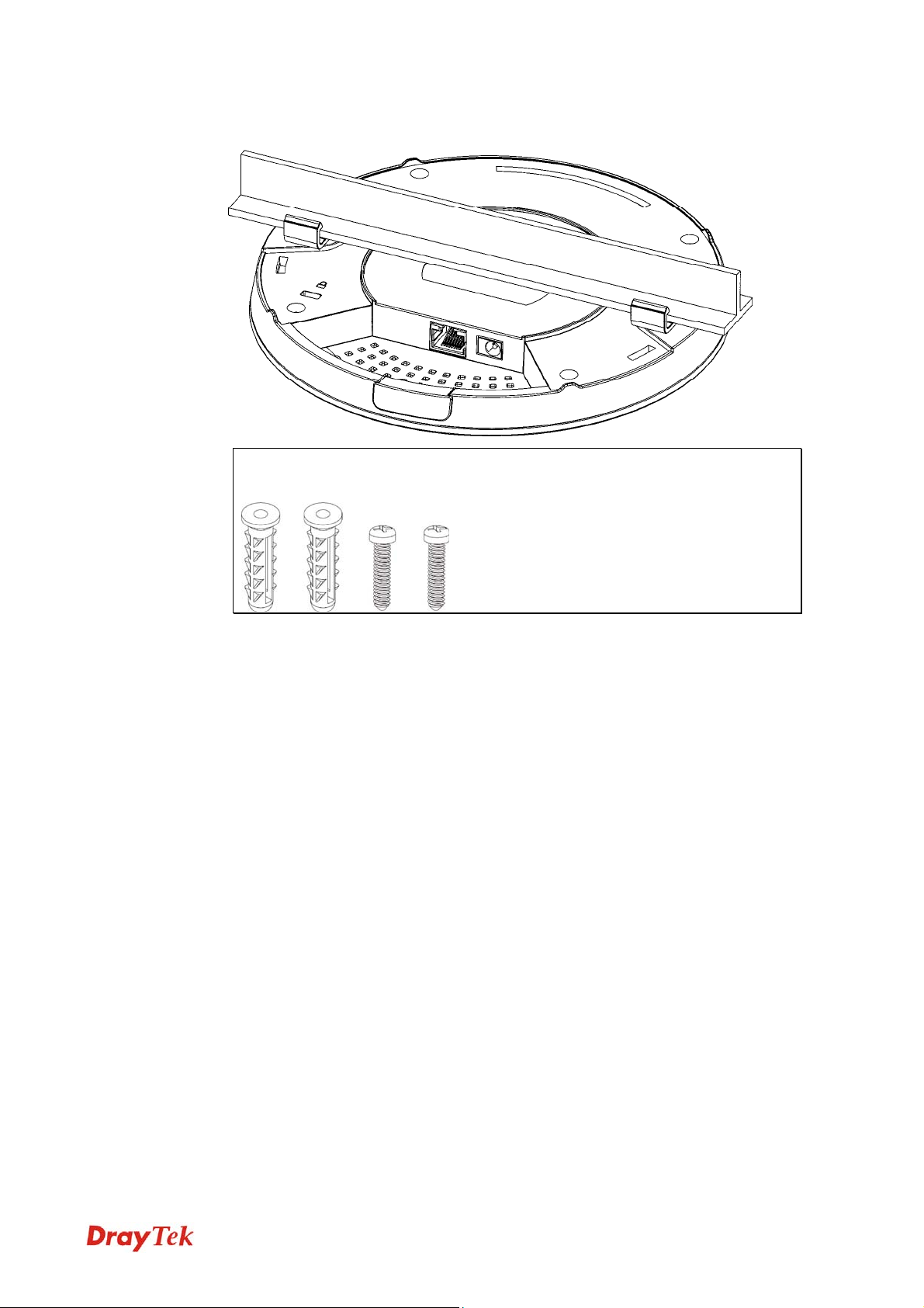
4. Use the T-Rail brackets to fasten the device on Light-weighted Steel Frame.
Warning: The screw set shown below is for wall mounting only. Do
not use such set for ceiling mounting due to the danger of falling.
7
VigorAP 910C User’s Guide
Page 16
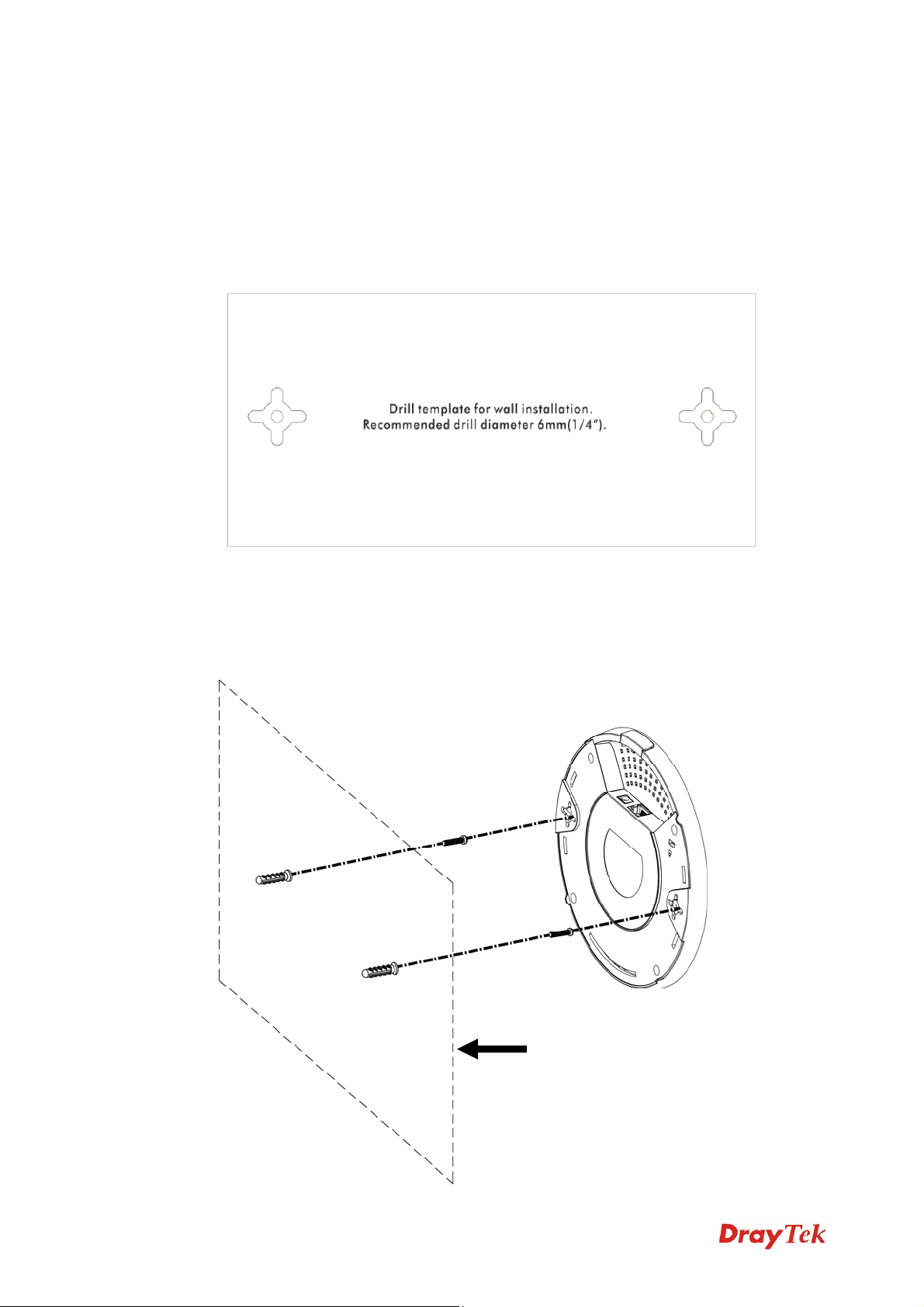
11..33..44 WWaallll MMoouunnttiinngg IInnssttaallllaattiioonn
For wall-mounting, the VigorAP has keyhole type mounting slots on the underside. You can
fit the AP at any axis (i.e. 12, 3, 6 or 9 O’Clock) to allow for cable entry from the most
convenient location if you are using side entry – note the position of the side entry cable
cutout.
1. A template is provided on the VigorAP’s packaging box to enable you to space the
screws correctly on the wall
2. Place the template on the wall and drill the holes according to the recommended
instruction.
.
3. Fit screws into the wall using the appropriate type of wall plug (as shown in the ceiling
section) but do not use the ceiling bracket – the VigorAP hangs directly onto the
screws.
Wall (wooden, concrete,
plasterboard or others)
VigorAP 910C User’s Guide
8
Page 17
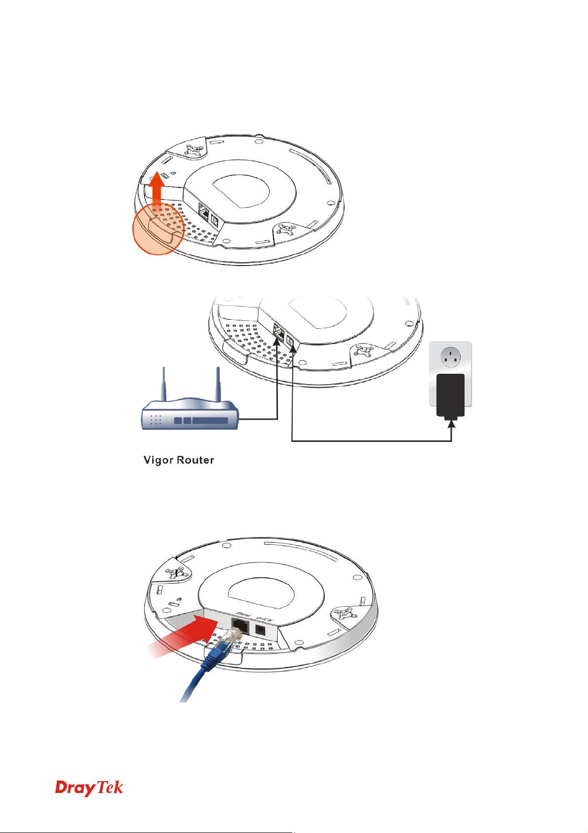
11..44 NNoottiiffiiccaattiioonnss ffoorr HHaarrddwwaarree CCoonnnneeccttiioonn
If required, remove the protective cap of VigorAP to create extra space for the cables to
pass through.
Connect VigorAP to Vigor router (via LAN port) with Ethernet cable.
Connect VigorAP to PoE switch (via LAN port) with Ethernet cable. For connecting with
PoE switch, do not connect the power adapter. VigorAP will get the power from the
switch directly.
9
VigorAP 910C User’s Guide
Page 18
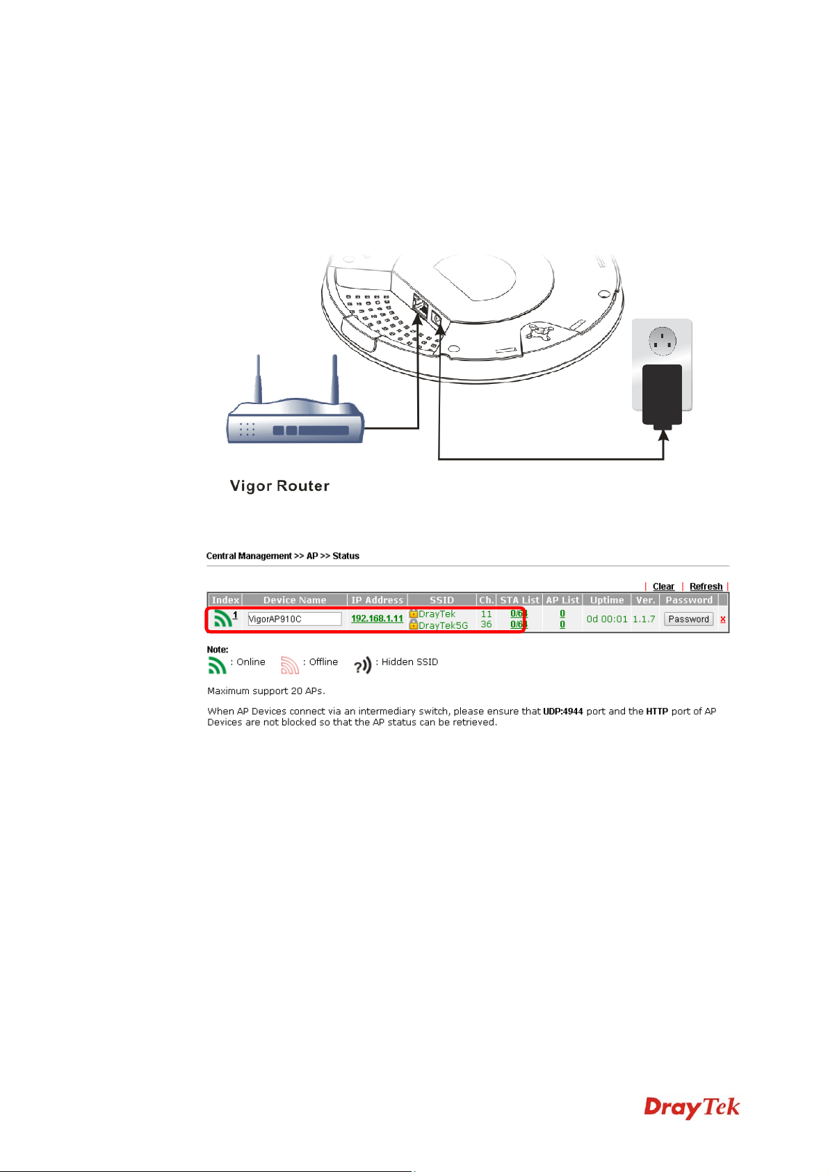
11..55 CCoonnnneecctt ttoo aa VViiggoorr RRoouutteerr uussiinngg AAPP MMaannaaggeemmeenntt
Your VigorAP can be used with Vigor routers which support AP management (such as the
Vigor 2862 or Vigor 2926 series). AP Management enables you to monitor and manage
multiple DrayTek APs from a single interface.
1. Connect one end of the power adapter to power port of VigorAP, and the other side into
a wall outlet.
2. Access into the web user interface of Vigor router. Here we take Vigor2862 as an
example. Open Central Management>> AP >>Status.
3. Locate VigorAP 910C. Click the IP address assigned by Vigor router to access into
web user interface of VigorAP 910C.
4. After typing username and password (admin/admin), the main screen will be displayed.
VigorAP 910C User’s Guide
10
Page 19
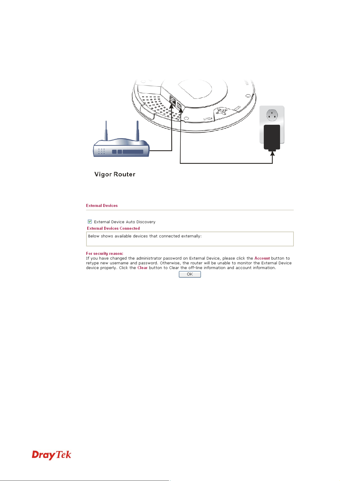
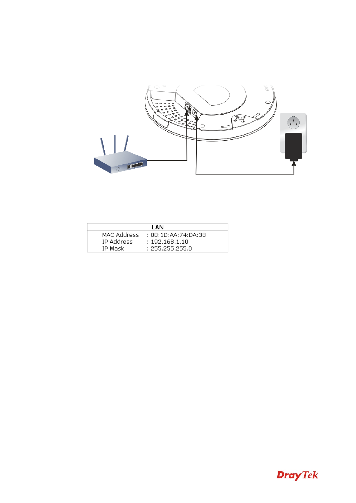
11..66 CCoonnnneecctt ttoo aa VViiggoorr RRoouutteerr wwiitthhoouutt AAPP MMaannaaggeemmeenntt
1. Connect one end of the power adapter to power port of VigorAP, and the other side into
a wall outlet.
2. Access into the web user interface of Vigor router. Here we take Vigor2830 as an
example. Open External Devices.
3. Check the box of External Device Auto Discovery and click OK. When the IP address
assigned by Vigor router appears, click it to access into web user interface of VigorAP
910C.
4. After typing username and password (admin/admin), the main screen will be displayed.
11
VigorAP 910C User’s Guide
Page 20
11..77 CCoonnnneecctt wwiitthhoouutt aa DDrraayyTTeekk RRoouutteerr//LLAANN
1. Connect one end of the power adapter to power port of VigorAP, and the other side into
a wall outlet.
2. Access into the web user interface of the router.
3. Check that DHCP table to find an entry with a MAC address matching the VigorAP –
the VigorAP’s MAC address is printed on a label on the base. Once you have the
VigorAP’s IP address, you can access its own web interface, as shown in section 4.6
4. After getting the IP address of VigorAP 910C, access into the web user interface of
VigorAP 910C through the web page of non-Vigor router.
VigorAP 910C User’s Guide
12
Page 21
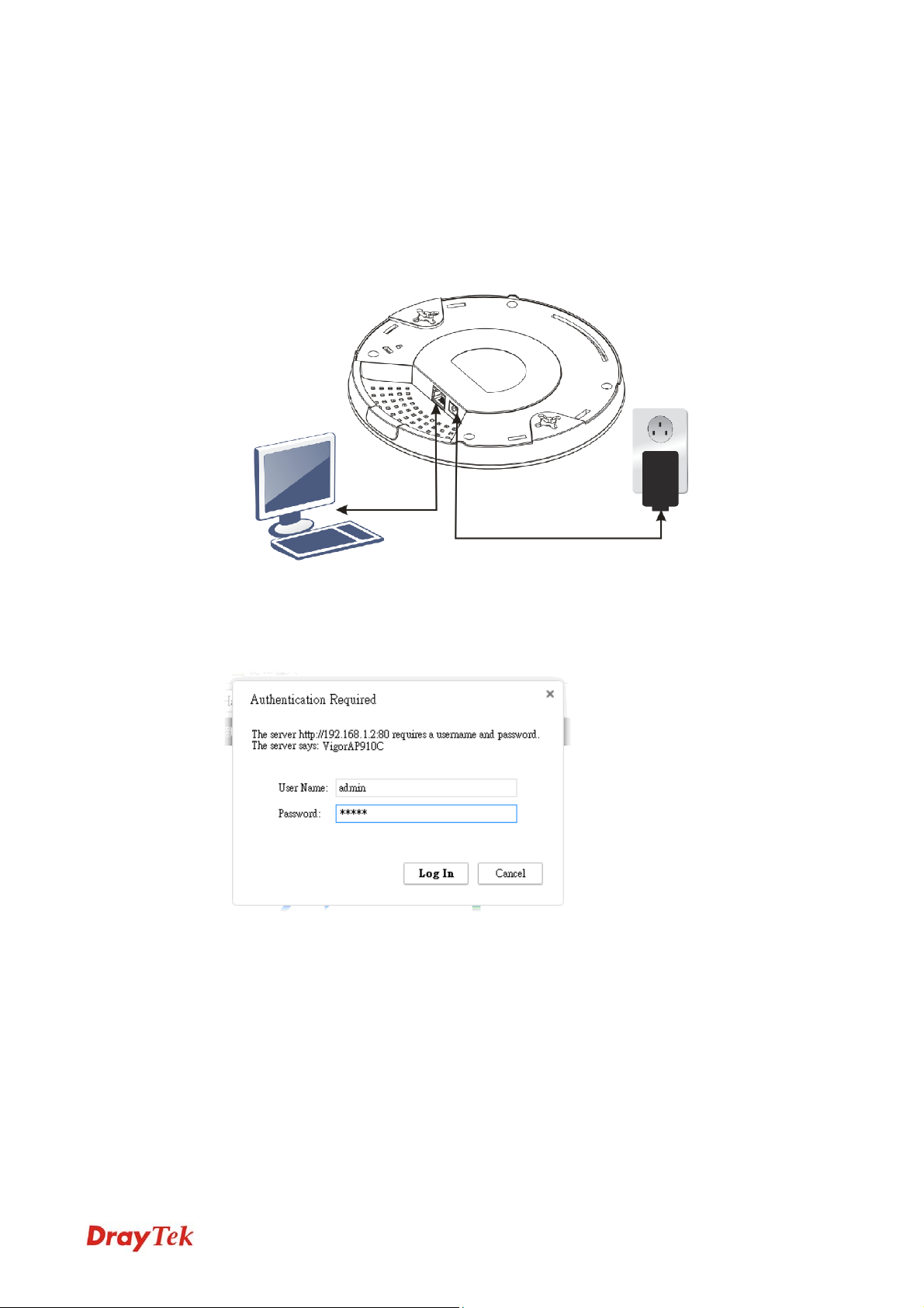
11..88 CCoonnnneeccttiinngg ttoo PPCC DDiirreeccttlly
1. Connect one end of an Ethernet cable (RJ-45) to one of the LAN ports of the VigorAP
and the other end of the cable (RJ-45) into the Ethernet port on your computer.
2. Connect one end of the power adapter to VigorAP’s power port on the bottom of the
device, and the other side into a wall outlet.
3. Wait for VigorAP initiation. When VigorAP is ready, the LED will blink in blue.
y
4. Set the IP address of the PC as “192.168.1.x (x means any number, ranges from 3 to
100).
5. Open a web browser on your PC and type http://192.168.1.2. The following window
will be open to ask for username and password. Type “admin/admin” and click Login.
6. Main screen will be displayed.
Before using VigorAP, finish the following web configuration first.
Configuring LAN IP address(es)
SSID and Security setting for 2.4G and 5GHz.
Administrator’s name and password.
Time and date.
For detailed, refer to Section 2.5 Accessing to Web User Interface.
13
VigorAP 910C User’s Guide
Page 22

This page is left blank.
VigorAP 910C User’s Guide
14
Page 23

Neett
N
After the network connection is built, the next step you should do is setup VigorAP 910C
with proper network parameters, so it can work properly in your network environment.
Before you can connect to the access point and start configuration procedures, your
computer must be able to get an IP address automatically (use dynamic IP address). If it’s set
to use static IP address, or you’re unsure, please follow the following instructions to
configure your computer to use dynamic IP address:
For the default IP address of this AP is set “192.168.1.2”, we recommend you to use
“192.168.1.X (except 2)” in the field of IP address on this section for your computer.
If the operating system of your computer is…
Windows 7 - please go to section 2.1
Windows 2000 - please go to section 2.2
Windows XP - please go to section 2.3
Windows Vista - please go to section 2.4
22..11 WWiinnddoowwss 77 IIPP AAddddrreessss SSeettuupp
Click Start button (it should be located at lower-left corner of your computer), then click
Control Panel. Double-click Network and Internet, and the following window will appear.
Click Network and Sharing Center.
woorrkk
w
Coonnffiigguurraattiioonn
C
Next, click Change adapter settings and click Local Area Connection.
15
VigorAP 910C User’s Guide
Page 24
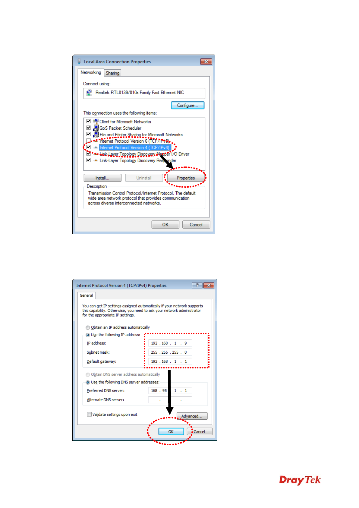
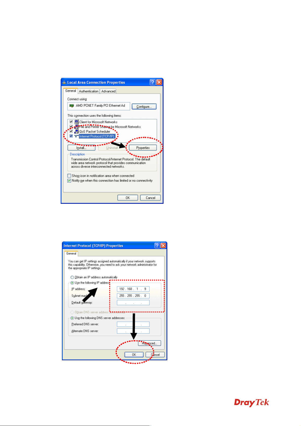
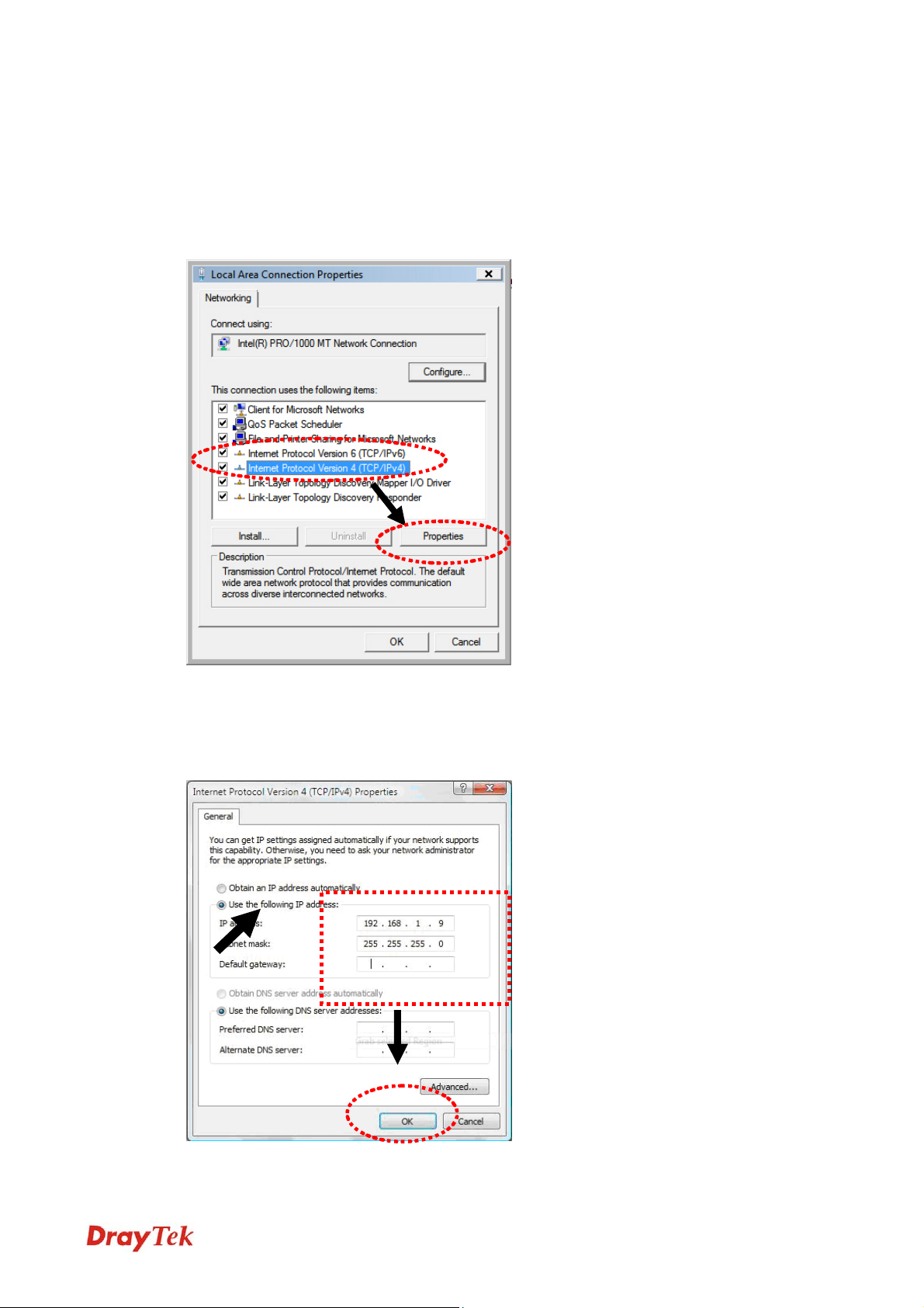
Then, select Internet Protocol Version 4 (TCP/IPv4) and click Properties.
Under the General tab, click Use the following IP address. Then input the following
settings in respective field and click OK when finish.
IP address: 192.168.1.9
Subnet Mask: 255.255.255.0
VigorAP 910C User’s Guide
16
Page 25
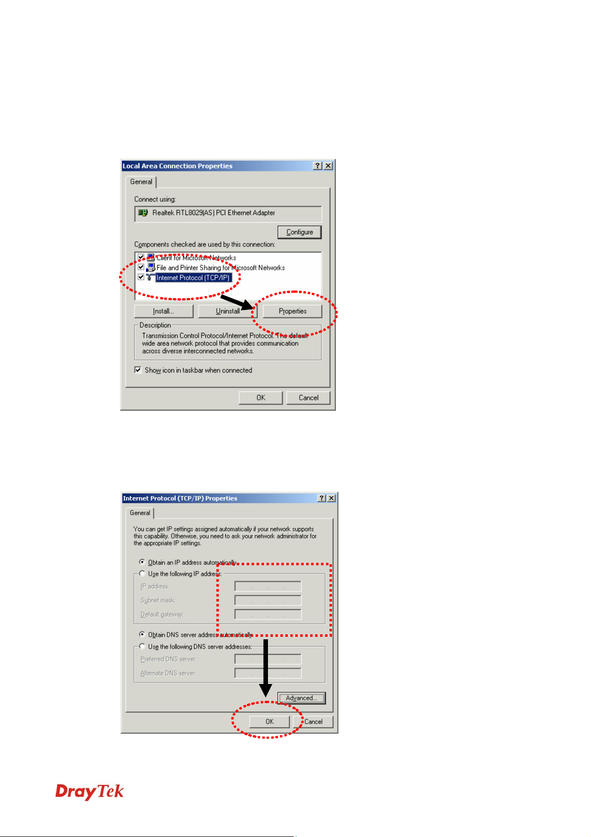
22..22 WWiinnddoowwss 22000000 IIPP AAddddrreessss SSeettuupp
Click Start button (it should be located at lower-left corner of your computer), then click
control panel. Double-click Network and Dial-up Connections icon, double click Local
Area Connection, and Local Area Connection Properties window will appear. Select
Internet Protocol (TCP/IP), then click Properties.
Select Use the following IP address, then input the following settings in respective field and
click OK when finish.
IP address: 192.168.1.9
Subnet Mask: 255.255.255.0
17
VigorAP 910C User’s Guide
Page 26
22..33 WWiinnddoowwss XXPP IIPP AAddddrreessss SSeettuupp
Click Start button (it should be located at lower-left corner of your computer), then click
control panel. Double-click Network and Internet Connections icon, click Network
Connections, and then double-click Local Area Connection, Local Area Connection
Status window will appear, and then click Properties.
Select Use the following IP address, then input the following settings in respective field and
click OK when finish:
IP address: 192.168.1.9
Subnet Mask: 255.255.255.0.
VigorAP 910C User’s Guide
18
Page 27
22..44 WWiinnddoowwss VViissttaa IIPP AAddddrreessss SSeettuupp
Click Start button (it should be located at lower-left corner of your computer), then click
control panel. Click View Network Status and Tasks, then click Manage Network
Connections. Right-click Local Area Netwrok, then select ‘Properties’. Local Area
Connection Properties window will appear, select Internet Protocol Version 4 (TCP /
IPv4), and then click Properties.
Select Use the following IP address, then input the following settings in respective field and
click OK when finish:
IP address: 192.168.1.9
Subnet Mask: 255.255.255.0.
19
VigorAP 910C User’s Guide
Page 28
22..55 AAcccceessssiinngg ttoo WWeebb UUsseerr IInntteerrffaaccee
All functions and settings of this access point must be configured via web user interface.
Please start your web browser (e.g., IE).
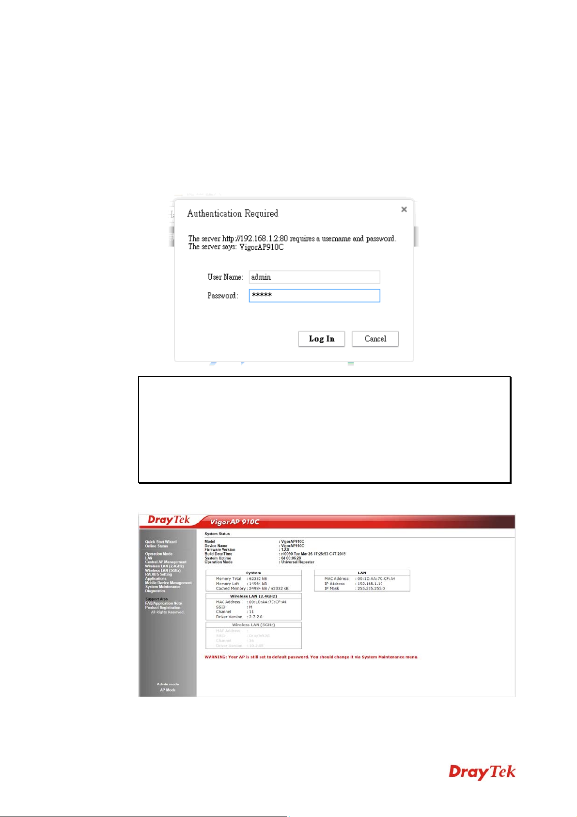
1. Make sure your PC connects to the VigorAP 910C correctly.
2. Open a web browser on your PC and type http://192.168.1.2. A pop-up window will
open to ask for username and password. Pease type “admin/admin” on
Username/Password and click OK.
Note: You may either simply set up your computer to get IP dynamically from the
router or set up the IP address of the computer to be in the same subnet as the IP
address of VigorAP 910C.
If there is no DHCP server on the network, then VigorAP 910C will have an IP
address of 192.168.1.2.
If there is DHCP available on the network, then VigorAP 910C will receive it’s
IP address via the DHCP server.
3. The Main Screen will pop up.
VigorAP 910C User’s Guide
20
Page 29
Note: If you fail to access to the web configuration, please go to “Trouble
Shooting” for detecting and solving your problem. For using the device properly, it
is necessary for you to change the password of web configuration for security and
adjust primary basic settings.
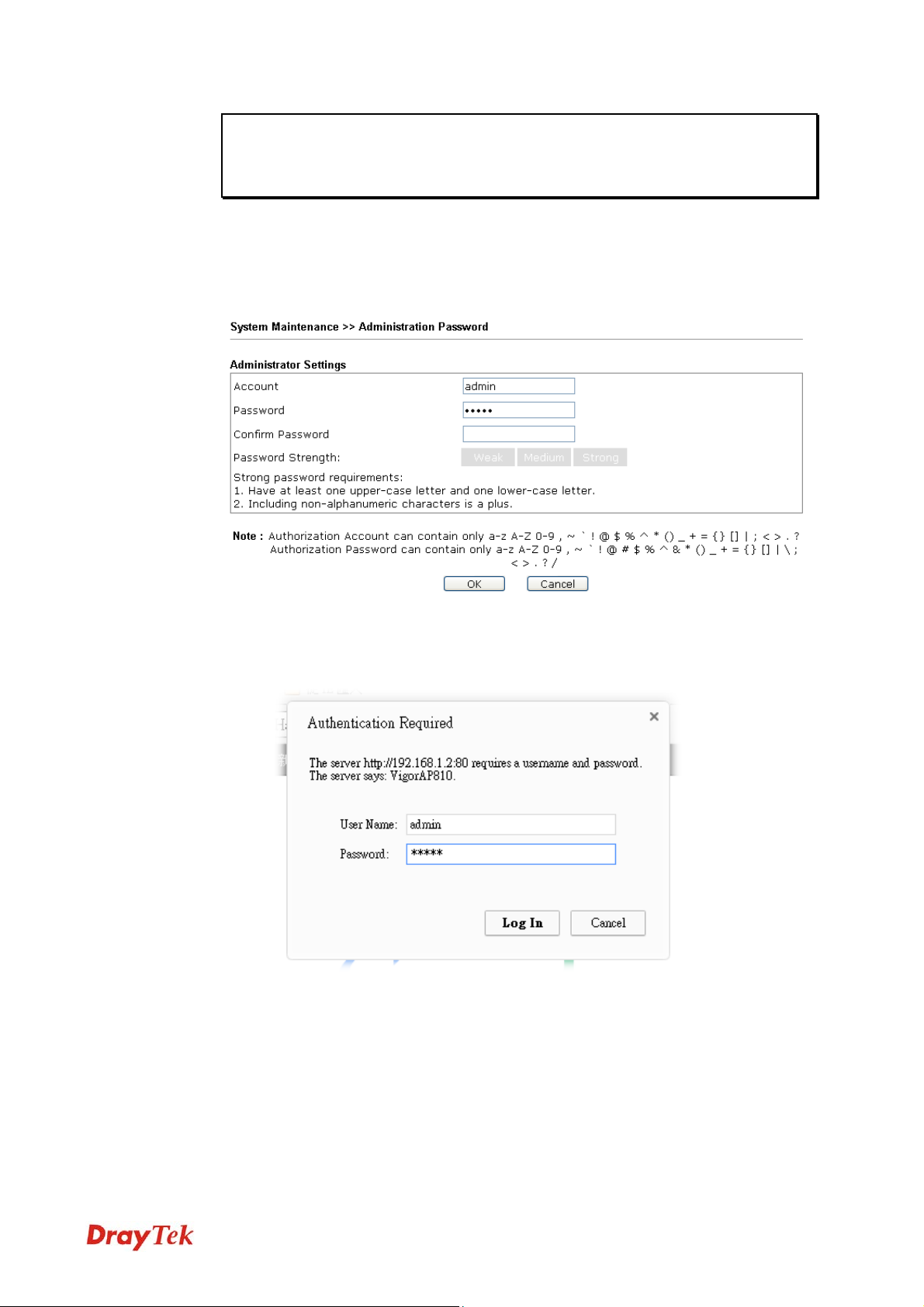
22..66 CChhaannggiinngg PPaasssswwoorrdd
1. Please change the password for the original security of the modem.
2. Go to System Maintenance page and choose Administration Password.
3. Enter the new login password on the field of Password. Then click OK to continue.
4. Now, the password has been changed. Next time, use the new password to access the
Web User Interface for this modem.
21
VigorAP 910C User’s Guide
Page 30
22..77 QQuuiicckk SSttaarrtt WWiizzaarrdd
Quick Start Wizard will guide you to configure 2.4G wireless setting, 5G wireless setting
and other corresponding settings for Vigor Access Point step by step.
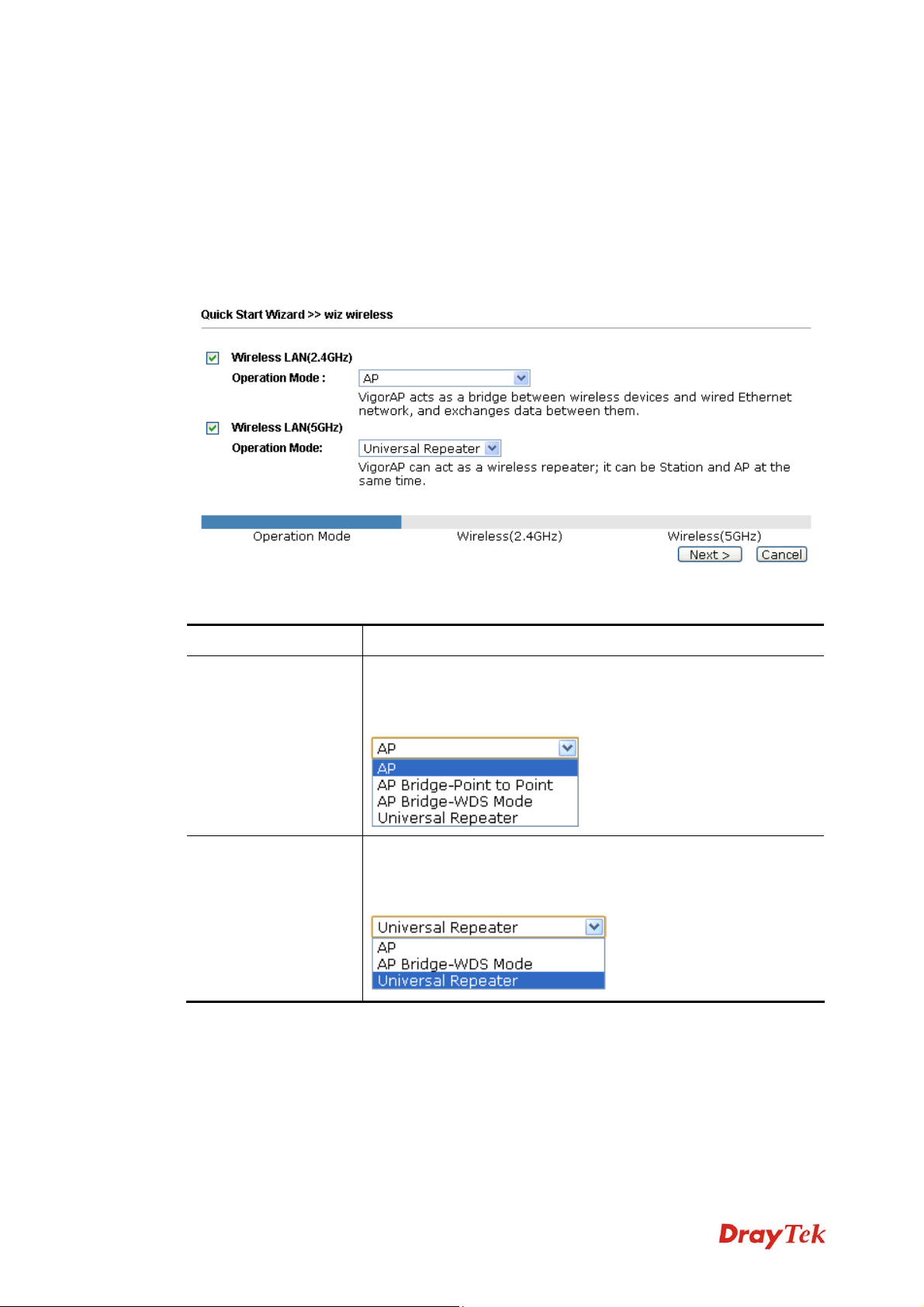
22..77..11 CCoonnffiigguurriinngg WWiirreelleessss SSeettttiinnggss –– GGeenneerraall
This page displays general settings (enable/disable wireless LAN 2.4GHz/5GHz) for the
operation mode selected.
Available settings are explained as follows:
Item Description
Wireless LAN
(2.4GHz)
Wireless LAN
(5GHz)
Check the box to enable WLAN 2.4GHz for VigorAP.
Operation Mode - There are four operation modes for wireless
connection. Settings for each mode are different.
Check the box to enable WLAN 5GHz for VigorAP.
Operation Mode - There are two operation modes for wireless
connection. Settings for each mode are different.
VigorAP 910C User’s Guide
22
Page 31

22..77..22 CCoonnffiigguurriinngg 22..44GGHHzz WWiirreelleessss SSeettttiinnggss BBaasseedd oon
In this page, the advanced settings will vary according to the operation mode chosen on
2.7.1.
SSeettttiinnggss ffoorr AAPP
When you choose AP as the operation mode for wireless LAN (2.4GHz), you will need to
configure the following page.
Available settings are explained as follows:
n tthhee OOppeerraattiioonn MMooddee
Item Description
Channel
Main SSID
Security Key
Means the channel frequency of the wireless LAN. The default
channel is 6. You may switch channel if the selected channel is
under serious interference. If you have no idea of choosing the
frequency, please select AutoSelect to let system determine for
you.
Set a name for VigorAP 910C to be identified.
Type 8~63 ASCII characters, such as 012345678..(or 64
Hexadecimal digits leading by 0x, such as "0x321253abcde...").
Enable Guest
Wireless
Check the box to enable the guest wireless setting.
Such feature is especially useful for free Wi-Fi service. For
example, a coffee shop offers free Wi-Fi service for its guests
23
VigorAP 910C User’s Guide
Page 32

for one hour every day.
SSID – Set a name for VigorAP 910C which can be identified
and connected by wireless guest.
Security Key– Set 8~63 ASCII characters or 8~63 ASCII
characters which can be used for logging into VigorAP 910C by
wireless guest.
Enable Bandwidth Limit – Check the box to define the
maximum speed of the data uploading/downloading which will
be used for the guest connecting to Vigor device with the same
SSID.
Upload Limit – Scroll the radio button to choose the
value you want.
Download Limit –Scroll the radio button to choose
the value you want.
Enable Station Control – Check the box to set the duration for
the guest connecting /reconnecting to Vigor device.
Connection Time –Scroll the radio button to choose
the value you want.
Reconnection Time –Scroll the radio button to
choose the value you want.
SSeettttiinnggss ffoorr AAPP BBrriiddggee--PPooiinntt ttoo PPooiinntt
When you choose AP Bridge-Point to Point as the operation mode for wireless LAN
(2.4GHz), you will need to configure the following page.
Available settings are explained as follows:
Item Description
AP Discovery
VigorAP 910C User’s Guide
Click this button to open the AP Discovery dialog. VigorAP
910C can scan all regulatory channels and find working APs in
the neighborhood.
24
Page 33

Phy Mode
Security
Peer MAC Address
Data will be transmitted via HTMIX mode.
Each access point should be setup to the same Phy Mode for
connecting with each other.
Select WEP, TKIP or AES as the encryption algorithm.
Type 8~63 ASCII characters, such as 012345678..(or 64
Hexadecimal digits leading by 0x, such as "0x321253abcde...").
Type the peer MAC address for the access point that VigorAP
910C connects to.
25
VigorAP 910C User’s Guide
Page 34

AAddvvaanncceedd SSeettttiinnggss ffoorr AAPP BBrriiddggee--WWDDSS
When you choose AP Bridge-WDS as the operation mode for wireless LAN (2.4GHz), you
will need to configure the following page.
Available settings are explained as follows:
Item Description
AP Discovery
Click this button to open the AP Discovery dialog. VigorAP
910C can scan all regulatory channels and find working APs in
the neighborhood.
Phy Mode
Data will be transmitted via HTMIX mode.
Each access point should be setup to the same Phy Mode for
connecting with each other.
Security
Select WEP, TKIP or AES as the encryption algorithm. Type the
key number if required.
Peer MAC Address
Type the peer MAC address for the access point that VigorAP
connects to.
Main SSID
Security Key
Set a name for VigorAP 910C to be identified.
Type 8~63 ASCII characters, such as 012345678..(or 64
Hexadecimal digits leading by 0x, such as "0x321253abcde...").
VigorAP 910C User’s Guide
26
Page 35

SSeettttiinnggss ffoorr UUnniivveerrssaall RReeppeeaatteerr
When you choose Universal Repeater as the operation mode for wireless LAN (2.4GHz),
you will need to configure the following page.
Available settings are explained as follows:
Item Description
Universal Repeater Parameters
AP Discovery
Click this button to open the AP Discovery dialog. VigorAP
910C can scan all regulatory channels and find working APs in
the neighborhood.
SSID / MAC Address
(Optional)
SSID means the identification of the wireless LAN. After
choosing one of the AP from AP Discovery window and
clicking OK, the settings (SSID and MAC Address) related to
the selected AP will be displayed on these fields automatically.
Later, VigorAP 910C will be allowed to access Internet through
the selected AP, by using SSID displayed here.
Channel
Means the channel of frequency of the wireless LAN. You may
switch channel if the selected channel is under serious
interference. If you have no idea of choosing the frequency,
please select AutoSelect to let system determine for you.
Security Mode
There are several modes provided for you to choose. Each mode
will bring up different parameters (e.g., WEP keys, Pass Phrase)
for you to configure.
27
VigorAP 910C User’s Guide
Page 36

Encryption Type for
Open/Shared
This option is available when Open/Shared is selected as
Security Mode.
Choose None to disable the WEP Encryption. Data sent to the
AP will not be encrypted. To enable WEP encryption for data
transmission, please choose WEP.
WEP Keys - Four keys can be entered here, but only one key
can be selected at a time. The format of WEP Key is restricted to
5 ASCII characters or 10 hexadecimal values in 64-bit
encryption level, or restricted to 13 ASCII characters or 26
hexadecimal values in 128-bit encryption level. The allowed
content is the ASCII characters from 33(!) to 126(~) except '#'
and ','.
Encryption Type for
WPA/PS K and
WPA2/PSK
Security Key
Use the same SSID
and Security Key as
Above
This option is available when WPA/PSK or WPA2/PSK is
selected as Security Mode.
Select TKIP or AES as the algorithm for WPA.
Type 8~63 ASCII characters, such as 012345678..(or 64
Hexadecimal digits leading by 0x, such as "0x321253abcde...").
Such feature is available for WPA/PSK or WPA2/PSK mode.
In general, under the network environment, same SSID and
security key can be used for the host (wireless client) and the
repeater (VigorAP 910C) in Universal Repeater mode. Check it
to use the same SSID and security key configured as above.
SSID - SSID can be any text numbers or various special
characters. For VigorAP 910C is set as “Repeater”, the purpose
of the device is to extend the Wi-Fi service. Therefore, the
characters set here will be regarded as “main SSID”. Other
wireless client can receive the wireless signal from VigorAP
910C by using the SSID configured here.
Security Key- Set 8~63 ASCII characters or 64 Hexadecimal
digits which can be used for logging into VigorAP 910C by
other wireless client.
Enable Guest
VigorAP 910C User’s Guide
Check the box to enable the guest wireless setting.
28
Page 37

Wireless
SSID – Set a name for VigorAP 910C. Wireless guest is allowed
to access into Internet via VigorAP 910C with the SSID
configured here.
Security – Set 8~63 ASCII characters or 64 Hexadecimal digits
which can be used for logging into VigorAP 910C by wireless
guest.
Enable Bandwidth Limit – Check the box to define the
maximum speed of the data uploading/downloading which will
be used for the guest connecting to Vigor device with the same
SSID.
Upload Limit –Scroll the radio button to choose the
value you want.
Download Limit –Scroll the radio button to choose
the value you want.
Enable Station Control – Check the box to set the duration for
the guest connecting /reconnecting to Vigor device.
Connection Time –Scroll the radio button to choose
the value you want.
Reconnection Time –Scroll the radio button to
choose the value you want.
After finishing this web page configuration, please click Next to continue.
29
VigorAP 910C User’s Guide
Page 38

22..77..33 CCoonnffiigguurriinngg 55GGHHzz WWiirreelleessss SSeettttiinnggss BBaasseedd oonn t
VigorAP 910C offers 5GHz wireless connection capability. You can setup 5G features in
Quick Start Wizard first. Once the USB 5GHz wireless dongle connects to VigorAP 910C, it
can work immediately.
SSeettttiinnggss ffoorr AAPP
After finished the configuration for wireless LAN (2.4GHz) and click Next, you will need to
configure the following page if you choose AP as the operation mode for wireless LAN
(5GHz).
thhee OOppeerraattiioonn MMooddee
Available settings are explained as follows:
Item Description
Channel
Main SSID
Security Key
Enable Guest
Wireless
Means the channel of frequency of the wireless LAN. The
default channel is 36. You may switch channel if the selected
channel is under serious interference.
Set a name for VigorAP 910C to be identified.
Type 8~63 ASCII characters, such as 012345678..(or 64
Hexadecimal digits leading by 0x, such as "0x321253abcde...").
Check the box to enable the guest wireless setting.
SSID – Set a name for VigorAP 910C which can be identified
and connected by wireless guest.
Security Key– Set 8~63 ASCII characters or 8~63 ASCII
characters which can be used for logging into VigorAP 910C by
wireless guest.
Enable Bandwidth Limit – Check the box to define the
maximum speed of the data uploading/downloading which will
be used for the guest connecting to Vigor device with the same
SSID.
VigorAP 910C User’s Guide
Upload Limit –Scroll the radio button to choose the
30
Page 39

value you want.
Download Limit –Scroll the radio button to choose
the value you want.
Enable Station Control – Check the box to set the duration for
the guest connecting /reconnecting to Vigor device.
Connection Time –Scroll the radio button to choose
the value you want.
Reconnection Time –Scroll the radio button to
choose the value you want.
After finishing this web page configuration, please click Next to continue.
SSeettttiinnggss ffoorr AAPP BBrriiddggee--WWDDSS MMooddee
After finished the configuration for wireless LAN (2.4GHz) and click Next, you will need to
configure the following page if you choose AP Bridge-WDS as the operation mode for
wireless LAN (5GHz).
Available settings are explained as follows:
Item Description
Security
Select WEP, TKIP or AES as the encryption algorithm.
Key – Enter a string as security key.
Peer Mac Address
Main SSID
Security Key
Enter the MAC address for the peer.
Set a name for VigorAP 910C to be identified.
Type 8~63 ASCII characters, such as 012345678..(or 64
Hexadecimal digits leading by 0x, such as "0x321253abcde...").
31
VigorAP 910C User’s Guide
Page 40

SSeettttiinnggss ffoorr UUnniivveerrssaall RReeppeeaatteerr
After finished the configuration for wireless LAN (2.4GHz) and click Next, you will need to
configure the following page if you choose Universal Repeater as the operation mode for
wireless LAN (5GHz).
Available settings are explained as follows:
Item Description
AP Discovery
Click this button to open the AP Discovery dialog. VigorAP
910C can scan all regulatory channels and find working APs in
the neighborhood.
SSID / MAC Address
(Optional)
SSID means the identification of the wireless LAN. After
choosing one of the AP from AP Discovery window and
clicking OK, the settings (SSID and MAC Address) related to
the selected AP will be displayed on these fields automatically.
Later, VigorAP 910C will be allowed to access Internet through
the selected AP, by using SSID displayed here.
Channel
Means the channel of frequency of the wireless LAN. The
default channel is 36. You may switch channel if the selected
channel is under serious interference.
Security Mode
There are several modes provided for you to choose. Each mode
will bring up different parameters (e.g., WEP keys, Pass Phrase)
for you to configure.
VigorAP 910C User’s Guide
32
Page 41

Encryption Type for
Open/Shared
This option is available when Open/Shared is selected as
Security Mode.
Choose None to disable the WEP Encryption. Data sent to the
AP will not be encrypted. To enable WEP encryption for data
transmission, please choose WEP.
WEP Keys - Four keys can be entered here, but only one key
can be selected at a time. The format of WEP Key is restricted to
5 ASCII characters or 10 hexadecimal values in 64-bit
encryption level, or restricted to 13 ASCII characters or 26
hexadecimal values in 128-bit encryption level. The allowed
content is the ASCII characters from 33(!) to 126(~) except '#'
and ','.
Encryption Type for
WPA/PS K and
WPA2/PSK
Security Key
Use the same SSID
and Security Key as
Above
This option is available when WPA/PSK or WPA2/PSK is
selected as Security Mode.
Select TKIP or AES as the algorithm for WPA.
Type 8~63 ASCII characters, such as 012345678..(or 64
Hexadecimal digits leading by 0x, such as "0x321253abcde...").
Such feature is available for WPA/PSK or WPA2/PSK mode.
In general, under the network environment, same SSID and
security key can be used for the host (wireless client) and the
repeater (VigorAP 910C) in Universal Repeater mode. Check it
to use the same SSID and security key configured as above.
SSID - SSID can be any text numbers or various special
characters. For VigorAP 910C is set as “Repeater”, the purpose
of the device is to extend the Wi-Fi service. Therefore, the
characters set here will be regarded as “main SSID”. Other
wireless client can receive the wireless signal from VigorAP
910C by using the SSID configured here.
Security Key - Set 8~63 ASCII characters or 64 Hexadecimal
digits which can be used for logging into VigorAP 910C by
other wireless client.
Enable Guest
Check the box to enable the guest wireless setting.
33
VigorAP 910C User’s Guide
Page 42

Wireless
SSID – Set a name for VigorAP 910C Wireless guest is allowed
to access into Internet via VigorAP 910C with the SSID
configured here.
Security – Set 8~63 ASCII characters or 64 Hexadecimal digits
which can be used for logging into VigorAP 910C by wireless
guest.
Enable Bandwidth Limit – Check the box to define the
maximum speed of the data uploading/downloading which will
be used for the guest connecting to Vigor device with the same
SSID.
Upload Limit –Scroll the radio button to choose the
value you want.
Download Limit –Scroll the radio button to choose
the value you want.
Enable Station Control – Check the box to set the duration for
the guest connecting /reconnecting to Vigor device.
Connection Time –Scroll the radio button to choose
the value you want.
Reconnection Time –Scroll the radio button to
choose the value you want.
After finishing this web page configuration, please click Next to continue.
VigorAP 910C User’s Guide
34
Page 43
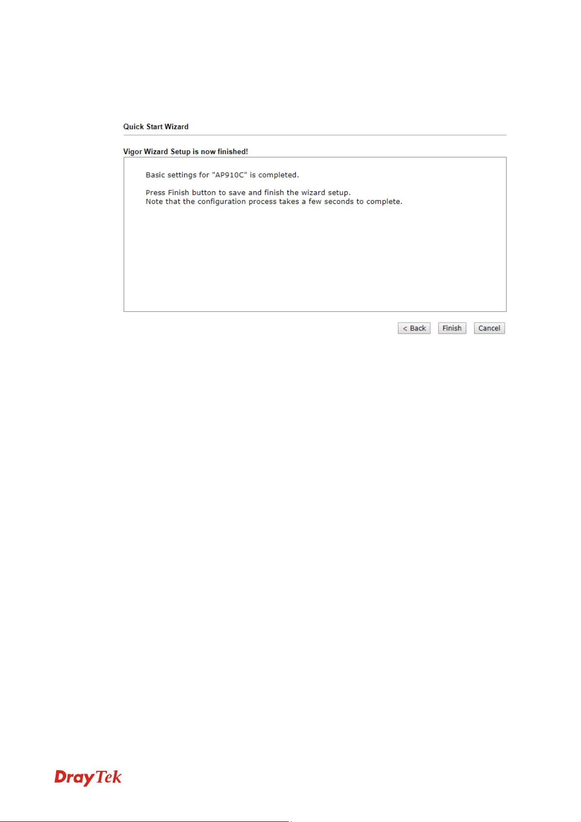
22..77..44 FFiinniisshhiinngg tthhee WWiirreelleessss SSeettttiinnggss WWiizzaarrdd
When you see this page, it means the wireless setting wizard is almost finished. Just click
Finish to save the settings and complete the setting procedure.
35
VigorAP 910C User’s Guide
Page 44

22..88 OOnnlliinnee SSttaattuuss
The online status shows the LAN status, Station Link Status for such device.
Detailed explanation is shown below:
Item Description
IP Address
TX Packets
RX Packets
Displays the IP address of the LAN interface.
Displays the total transmitted packets at the LAN interface.
Displays the total number of received packets at the LAN
interface.
TX Bytes
RX Bytes
Displays the total transmitted size at the LAN interface.
Displays the total number of received size at the LAN interface.
.
VigorAP 910C User’s Guide
36
Page 45

Addvvaanncceedd
A
This chapter will guide users to execute advanced (full) configuration. As for other examples
of application, please refer to chapter 5.
1. Open a web browser on your PC and type http://192.168.1.2. The window will ask for
typing username and password.
2. Please type “admin/admin” on Username/Password for administration operation.
Now, the Main Screen will appear. Be aware that “Admin mode” will be displayed on the
bottom left side.
Coonnffiigguurraattiioonn
C
37
VigorAP 910C User’s Guide
Page 46

33..11 OOppeerraattiioonn MMooddee
This page provides several available modes for you to choose for different conditions. Click
any one of them and click OK. The system will configure the required settings
automatically.
Available settings are explained as follows:
Item Description
Wireless LAN(2.4GHz)
AP
Station-Infrastructure
AP Bridge-Point to
Point
AP Bridge-Point to
Multi-Point
VigorAP 910C User’s Guide
This mode allows wireless clients to connect to access point and
exchange data with the devices connected to the wired network.
Enable the Ethernet device such as TV and Game player
connected to the VigorAP 910C to an access point.
This mode can establish wireless connection with another
VigorAP 910C using the same mode, and link the wired network
which these two VigorAP 910Cs connected together. Only one
access point can be connected in this mode.
This mode can establish wireless connection with other VigorAP
910Cs using the same mode, and link the wired network which
these VigorAP 910Cs connected together. Up to 4 access points
38
Page 47

can be connected in this mode.
AP Bridge-WDS
Universal Repeater
Wireless LAN(5GHz)
AP
AP Bridge-WDS
Universal Repeater
This mode is similar to AP Bridge to Multi-Point, but access
point is not work in bridge-dedicated mode, and will be able to
accept wireless clients while the access point is working as a
wireless bridge.
This product can act as a wireless range extender that will help
you to extend the networking wirelessly. The access point can
act as Station and AP at the same time. It can use Station
function to connect to a Root AP and use AP function to service
all wireless clients within its coverage.
This mode allows wireless clients to connect to access point and
exchange data with the devices connected to the wired network.
This mode is similar to AP Bridge to Multi-Point, but access
point is not work in bridge-dedicated mode, and will be able to
accept wireless clients while the access point is working as a
wireless bridge.
This product can act as a wireless range extender that will help
you to extend the networking wirelessly. The access point can
act as Station and AP at the same time. It can use Station
function to connect to a Root AP and use AP function to service
all wireless clients within its coverage.
Note: The Wireless LAN settings will be changed according to the Operation Mode
selected here. For the detailed information, please refer to the section of Wireless LAN.
33..22 LLAANN
Local Area Network (LAN) is a group of subnets regulated and ruled by modem.
33..22..11 GGeenneerraall SSeettuupp
Click LAN to open the LAN settings page and choose General Setup.
Note: Such page will be changed according to the Operation Mode selected. The
following screen is obtained by choosing AP as the operation mode.
39
VigorAP 910C User’s Guide
Page 48

Available settings are explained as follows:
Item Description
LAN IP Network
Configuration
Enable DHCP Client – When it is enabled, VigorAP 910C will
be treated as a client and can be managed / controlled by AP
Management server offered by Vigor router (e.g., Vigor2862).
IP Addr ess – Type in private IP address for connecting to a local
private network (Default: 192.168.1.2).
Subnet Mask – Type in an address code that determines the size
of the network. (Default: 255.255.255.0/ 24)
Default Gateway - In general, it is not really necessary to
specify a gateway for VigorAP 902. However, if it is required,
simply type an IP address as the gateway for VigorAP 902. It
will be convenient for the access point to acquire more service
(e.g., accessing NTP server) from Vigor router.
Enable Management VLAN – VigorAP 910C supports
tag-based
VLAN for wireless clients accessing Vigor device. Only the
clients with the specified VLAN ID can access into VigorAP
910C.
DHCP Server
Configuration
VigorAP 910C User’s Guide
VLAN ID – Type the number as VLAN ID tagged on the
transmitted packet. “0” means no VALN tag.
DHCP stands for Dynam ic Host Configuration Protocol. DHCP
server can automatically dispatch related IP settings to any local
user configured as a DHCP client.
will
Enable Server – When it is enabled, VigorAP
assign
req u i r e d i n f o rmatio n ( e . g . , IP address, DNS server) to every host
in LAN.
40
Page 49

Start IP Address - Enter a value of the IP address pool for
the
DHCP server to start with when issuing IP addresses. If
the 1st
IP address of your modem is 192.168.1.2, the
starting IP address
must be 192.168.1.3 or greater, but
smaller than 192.168.1.254.
End IP Address - Enter a value of the IP address pool for
the
DHCP server to end with w hen issuing IP addresses.
Subnet Mask - Typ e in an address code that dete rmine s the
size of the network. (Default: 255.255.255.0/ 24)
Default Gateway - Enter a value of the gateway IP address
the DHCP serve r.
for
Lease Time - It allows you to set the leased time for the
specified PC.
Primary DNS Server - You must specify a DNS server IP
address here because your ISP should provide you with
usually
provide it, the
Server IP address:
more than one DNS Se r ve r . If your ISP does not
modem will automati cally apply default DNS
194.109.6.66 to this field.
Secondary DNS Server - Y o u can specify secondary DNS
server
more than
the modem will
IP address here because your ISP often provide s you
one DNS Server. If your ISP does not provide it,
automatically apply default secondary DNS
Server IP address: 194.98.0.1 to this field.
Disable Server - Disable Server lets you manually use other
DHCP server to
assign IP address to every host in the LAN.
Trust DHCP Server IP for WLAN - When the built-in
DHCP server of VigorAP is disabled, the wireless client
might get IP address from other DHCP server. Sometimes,
it might cause wireless client obtaining wrong IP or unable
to access internet. To solve this problem, simply specify a
DHCP server in this field. Then, the wireless client
connecting to such VigorAP will get IP address from this
specified DHCP server only.
DNS Server IP
Address
Relay Agent - Specify which subnet that DHCP server is located
the relay agent should redirect the DHCP request to.
DHCP Relay Agent - It is available
Agent is selected. Set the IP address of the
you are going to use so the Relay Agent can help
when Enable Relay
DHCP server
to forward
the DHCP request to the DHCP server.
Set the DNS server IP address for VigorAP.
Primary IP A d d r e s s- Yo u must specify a DNS server IP
address here because your ISP should provide you with
usually
provide it, the
Server IP address:
Secondary IP A d d r es s - Y ou can specify secondary
more than one DNS Se r ve r . If your ISP does not
modem will automati cally apply default DNS
194.109.6.66 to this field.
DNS server IP address here because your ISP often
provides you more than one DNS Server. If your ISP
41
VigorAP 910C User’s Guide
Page 50

does not provide it, the modem will automatically
apply default secondary DNS Server IP address:
194.98.0.1 to this field.
After finishing this web page configuration, please click OK to save the settings.
VigorAP 910C User’s Guide
42
Page 51

33..22..22 WWeebb PPoorrttaall
This page allows you to configure a profile with specified URL for accessing into or display
a message when a wireless/LAN user connects to Internet through this router. No matter
what the purpose of the wireless/LAN client is, he/she will be forced into the URL
configured here while trying to access into the Internet or the desired web page through this
router. That is, a company which wants to have an advertisement for its products to users can
specify the URL in this page to reach its goal.
Each item is explained as follows:
Item Description
Index
Display the number link which allows you to configure the
profile.
Enable
Comments
Check the box to enable such profile.
Display the content (Disable, URL Redirect or Message) of the
profile.
Login Mode
Interface
Preview
Display the login mode that a client uses to access into Internet.
Display the applied interfaces of the profile.
Open a preview window according to the configured settings.
After finishing this web page configuration, please click OK to save the settings.
43
VigorAP 910C User’s Guide
Page 52

To configure the profile, click any index number link to open the following page.
Available settings are explained as follows:
Item Description
Enable
Comments
Welcome message
Check the box to enable this function.
Enter a brief comment to explain such web portal profile.
Enter words or sentences here. The message will be displayed on
the screen for several seconds when the wireless users access
into the web page through the router.
Default – Click it to restore the default content.
Redirect Page
None - User can access into Internet directly.
URL Redirect - Any user who wants to access into Internet
through this router will be redirected to the URL specified here
first. It is a useful method for the purpose of advertisement. For
example, force the wireless user(s) in hotel to access into the
web page that the hotel wants the user(s) to visit.
Authentication
None – User can access into Internet directly without
authentication.
Button Click – When a client tries to access into Internet, a
welcome message page with a button named “Accept” will
appear on the screen first. The client must click that button
(Accept) and then he/she is allowed to access Internet.
Applied Interfaces
VigorAP 910C User’s Guide
Check the box(es) representing different interfaces to be applied
by such profile.
44
Page 53

LAN – If it is selected and Universal Repeater is specified
as connection mode for such AP, both LAN client and
WLAN client can access into Internet via web portal. Yet,
if AP mode is selected, only wireless LAN client shall
access into Internet via web portal.
WLAN 2.4GHz/5GHz - The advantage is that each SSID
(1/2/3/4) for wireless network can be applied with different
web portal separately.
After finishing all the settings here, please click OK to save the configuration.
45
VigorAP 910C User’s Guide
Page 54

33..33 CCeennttrraall AAPP MMaannaaggeemmeenntt
Central AP Management allows you to configure VigorAP 910C to be managed by
Vigor2862 series.
33..33..11 GGeenneerraall SSeettuupp
Available settings are explained as follows:
Item Description
Enable AP
Management
Enable Auto
Provision
Check the box to enable the function of AP Management.
VigorAP 910C can be controlled under Central AP Management
in Vigor2862 series. When both Vigor2862 series and VigorAP
910C have such feature enabled, once VigorAP 910C is
registered to Vigor2862 series, the WLAN profile
pre-configured on VigorAP2860 series will be applied to
VigorAP 910C immediately. Thus, it is not necessary to
VigorAP 910C User’s Guide
46
Page 55

configure VigorAP 910C separately.
33..33..22 AAPPMM LLoogg
This page will display log information related to wireless stations connected to VigorAP
910C and central AP management.
Such information also will be delivered to Vigor router (e.g., Vigor2862 or Vigor2926 series)
and be shown on Central AP Management>>Event Log of Vigor router.
33..33..33 FFuunnccttiioonn SSuuppppoorrtt LLiisstt
This page lists the AP management functions that the Access Points support under different
firmware versions.
Note: DrayTek central wireless management (AP Management) lets control, efficiency,
monitoring and security of your company-wide wireless access easier be managed. Inside
the web user interface, we call “central wireless management” as Central AP Management
which supports mobility, client monitoring/reporting and load-balancing to multiple APs.
47
VigorAP 910C User’s Guide
Page 56

For central wireless management, you will need a Vigor2862 or Vigor2926 series router;
there is no per-node licensing or subscription required. With the unified user interface of
Vigor2862 Combo WAN series and Vigor2926 Triple WAN series, the multiple
deployment of VigorAP 910C can be clear at the first sight. For multiple wireless clients,
to apply the AP Load Balancing to the multiple APs will manage wireless traffic with
smooth flow and enhanced efficiency.
33..33..44 OOvveerrllooaadd MMaannaaggeemmeenntt
Load Balance can help to distribute the traffic for all of the access points (e.g., VigorAP
910C) registered to Vigor router. Thus, the bandwidth will not be occupied by certain access
points.
However, traffic overload might be occurred if too many wireless stations connected to
VigorAP 910C for data incoming and outgoing. Therefore, “Force Overload Disassociation”
is required to terminate the network connection of the client’s station to release network
traffic. When the function of “Force Overload Disassociation” in web user interface of Vigor
router (e.g., Vigor2862 or Vigor2926 series) is enabled, wireless clients specified in black
list of such web page will be disassociated to solve the problem of traffic overload.
The following web page is used to configure white list and black list for wireless stations.
Available settings are explained as follows:
Item Description
White List/Black List
Client’s MAC
Address
VigorAP 910C User’s Guide
Display the information (such as index number, MAC address
and comment) for all of the members in White List/Black List.
Wireless stations listed in Black List will be forcefully
disconnected first when traffic overload occurs and “Force
Overload Disassociation” is enabled.
Specify the MAC Address of the remote/local client.
48
Page 57

Apply to
Comment
Add
Delete
Edit
Cancel
33..33..55 SSttaattuuss ooff SSeettttiinnggss
Load Balance can help to distribute the traffic for all of the access points (e.g.,
VigorAP910C) registered to Vigor2862 or Vigor2926 series. This web page displays the
settings related to Load Balance for VigorAP 910C. In which, By Station Number, By
Traffic and Force Overload Disassociation indicate settings configured in Vigor2862 or
Vigor2926 series.
White List – MAC address listed inside Client’s MAC Address
will be categorized as one of members in White List.
Black List - MAC address listed inside Client’s MAC Address
will be categorized as one of members in Black List.
Type any words as notification.
Add a new MAC address into the White List/Black List.
Delete the selected MAC address in the White List/Black List.
Edit the selected MAC address in the White List/Black List.
Give up the configuration.
49
VigorAP 910C User’s Guide
Page 58

33..44 GGeenneerraall CCoonncceeppttss ffoorr WWiirreelleessss LLAANN ((22..44GGHHzz//55GGHHzz))
VigorAP 910C is equipped with a wireless LAN interface compliant with 5GHz 802.11ac or
2.4/5 GHz 802.11n WLAN applications. To boost its performance further, the VigorAP
910C is also loaded with advanced wireless technology to lift up data rate up to 300 Mbps*.
Hence, you can finally smoothly enjoy stream music and video.
Note:
* The actual data throughput will vary according to the network conditions and
environmental factors, including volume of network traffic, network overhead and
building materials.
In an Infrastructure Mode of wireless network, VigorAP 910C plays a role as an Access
Point (AP) connecting to lots of wireless clients or Stations (STA). All the STAs will share
the same Internet connection via VigorAP 910C. The General Setup will set up the
information of this wireless network, including its SSID as identification, located channel
etc.
SSeeccuurriittyy OOvveerrvviieeww
WEP (Wired Equivalent Privacy) is a legacy method to encrypt each frame transmitted via
radio using either a 64-bit or 128-bit key. Usually access point will preset a set of four keys
and it will communicate with each station using only one out of the four keys.
WPA (Wi-Fi Protected Access), the most dominating security mechanism in industry, is
separated into two categories: WPA-personal or called WPA Pre-Share Key (WPA/PSK),
and WPA-Enterprise or called WPA/802.1x.
In WPA-Personal, a pre-defined key is used for encryption during data transmission. WPA
applies Temporal Key Integrity Protocol (TKIP) for data encryption while WPA2 applies
AES. The WPA-Enterprise combines not only encryption but also authentication.
Since WEP has been proved vulnerable, you may consider using WPA for the most secure
connection. You should select the appropriate security mechanism according to your needs.
No matter which security suite you select, they all will enhance the over-the-air data
protection and /or privacy on your wireless network. The VigorAP 910C is very flexible and
can support multiple secure connections with both WEP and WPA at the same time.
VigorAP 910C User’s Guide
50
Page 59
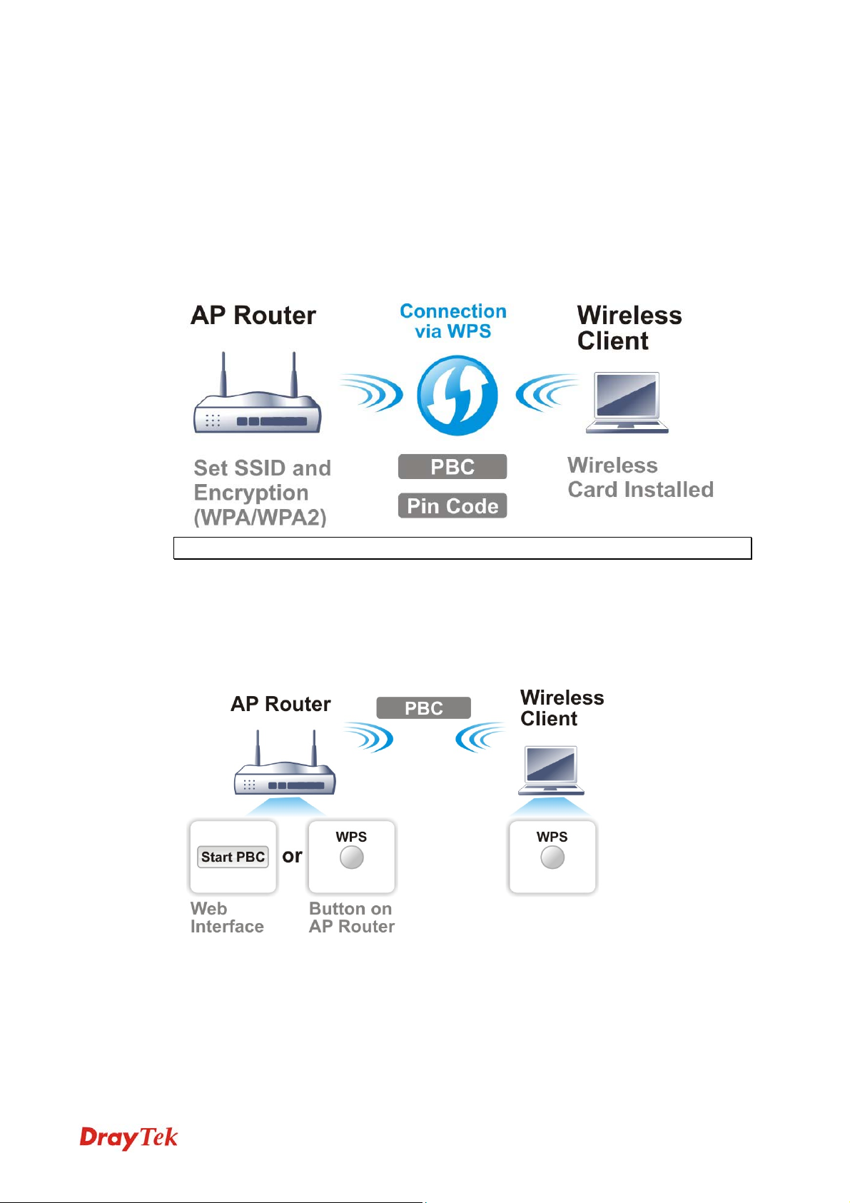
WWPPSS IInnttrroodduuccttiioonn
WPS (Wi-Fi Protected Setup) provides easy procedure to make network connection
between wireless station and wireless access point (VigorAP 910C) with the encryption of
WPA and WPA2.
It is the simplest way to build connection between wireless network clients and VigorAP
910C. Users do not need to select any encryption mode and type any long encryption
passphrase to setup a wireless client every time. He/she only needs to press a button on
wireless client, and WPS will connect for client and VigorAP 910C automatically.
Note: Such function is available for the wireless station with WPS supported.
There are two methods to do network connection through WPS between AP and Stations:
pressing the Start PBC button or using PIN Code.
On the side of VigorAP 910C series which served as an AP, press WPS button once on the
front panel of VigorAP 910C or click Start PBC on web configuration interface. On the side
of a station with network card installed, press Start PBC button of network card.
51
VigorAP 910C User’s Guide
Page 60

If you want to use PIN code, you have to know the PIN code specified in wireless client.
Then provide the PIN code of the wireless client you wish to connect to the VigorAP 910C.
VigorAP 910C User’s Guide
52
Page 61

33..55 WWiirreelleessss LLAANN ((22..44GGHHzz)) SSeettttiinnggss ffoorr AAPP MMooddee
When you choose AP as the operation mode, the Wireless LAN menu items will include
General Setup, Security, Access Control, WPS, Advanced Setting, AP Discovery, WMM
Configuration, Bandwidth Management, Airtime Fairness, Station Control, Roaming, Band
Steering and Station List.
Note: The Wireless LAN
Operation Mode selected in section 3.1.
(2.4GHz) settings will be changed according to the
33..55..11 GGeenneerraall SSeettuupp
By clicking the General Setup, a new web page will appear so that you could configure the SSID and the wireless channel. Please refer to the following figure for more information.
Available settings are explained as follows:
53
VigorAP 910C User’s Guide
Page 62

Item Description
Enable Wireless LAN
Enable Client Limit
Enable Client Limit
per SSID
Mode
Channel
Extension Channel
Enable
Hide SSID
Check the box to enable wireless function.
Check the box to set the maximum number of wireless stations
which try to connect Internet through Vigor AP. The number
you can set is from 3 to 64.
Define the maximum number of wireless stations per SSID
which try to connect to Internet through Vigor device. The
number you can set is from 3 to 64.
VigorAP 910C can connect to stations su p por ting 11b only, 11g
only,
11n only, Mixed (11b+11g), Mixed (11g+11n) and Mixed
(11b+11g+11n) for 2.4GHz simultaneously.
Means the channel of frequency of the wireless LAN. You may
switch channel if the selected channel is under serious
interference. If you have no idea of choosing the frequency,
please select AutoSelect to let system determine for you.
With 802.11n, there is one option to double the bandwidth per
channel. The available extension channel options will be varied
according to the Channel selected above. Configure the
extension channel you want.
Check the box to enable the SSID configuration.
Check it to prevent from wireless sniffing and make it harder
for unauthorized clients or STAs to join your wireless LAN.
Depending on the wireless utility, the user may only see the
44information except SSID or just cannot see any thing about
VigorAP 910C while site surveying. The system allows you to
set three sets of SSID for different usage.
SSID
Set a name for VigorAP 910C to be identified. Default settings
are DrayTek.
Isolate Member
Check this box to make the wireless clients (stations) with the
same SSID not accessing for each other.
VLAN ID
Type the value for such SSID. Packets transferred from such
SSID to LAN will be tagged with the number.
If your network uses VLANs, you can assign the SSID to a
VLAN on your network. Client devices that associate using the
SSID are grouped into this VLAN. The VLAN ID range is
from 3 to 4095. The VLAN ID is 0 by default, it means
disabling the VLAN function for the SSID.
After finishing this web page configuration, please click OK to save the settings.
VigorAP 910C User’s Guide
54
Page 63

33..55..22 SSeeccuurriittyy
This page allows you to set security with different modes for SSID 1, 2, 3 and 4 respectively.
After configuring the correct settings, please click OK to save and invoke it.
By clicking the Security Settings, a new web page will appear so that you could configure
the settings.
Available settings are explained as follows:
Item Description
Mode
There are several modes provided for you to choose.
Disable - The encryption mechanism is turned off.
WEP - Accepts only WEP clients and the encryption key
should be entered in WEP Key.
WPA/PSK or WPA2/PSK or Mixed (WPA+WPA2)/PSK -
Accepts only WPA clients and the encryption key should be
entered in PSK. The WPA encrypts each frame transmitted
from the radio using the key, which either PSK (Pre-Shared
Key) entered manually in this field below or automatically
negotiated via 802.1x authentication.
55
VigorAP 910C User’s Guide
Page 64

WEP/802.1x - The built-in RADIUS client feature enables
VigorAP 910C to assist the remote dial-in user or a wireless
station and the RADIUS server in performing mutual
authentication. It enables centralized remote access
authentication for network management.
The WPA encrypts each frame transmitted from the radio
using the key, which either PSK (Pre-Shared Key) entered
manually in this field below or automatically negotiated via
802.1x authentication. Select WPA, WPA2 or Auto as WPA
mode.
WPA/802.1x - The WPA encrypts each frame transmitted
from the radio using the key, which either PSK (Pre-Shared
Key) entered manually in this field below or automatically
negotiated via 802.1x authentication.
WPA2/802.1x - The WPA encrypts each frame transmitted
from the radio using the key, which either PSK (Pre-Shared
Key) entered manually in this field below or automatically
negotiated via 802.1x authentication.
WP A Algorithms
Pass Phrase
Key Renewal Interval
EAPOL Key Retry
Select TKIP, AES or TKIP/AES as the algorithm for WPA.
Such feature is available for WPA2/802.1x, WPA/802.1x,
WPA/PSK or WPA2/PSK or Mixed (WPA+WPA2)/PSK
mode.
Either 8~63 ASCII characters, such as 012345678(or 64
Hexadecimal digits leading by 0x, such as
"0x321253abcde..."). Such feature is available for WPA/PSK
or WPA2/PSK or Mixed (WPA+WPA2)/PSK mode.
WPA uses shared key for authentication to the network.
However, normal network operations use a different
encryption key that is randomly generated. This randomly
generated key that is periodically replaced. Enter the renewal
security time (seconds) in the column. Smaller interval leads to
greater security but lower performance. Default is 3600
seconds. Set 0 to disable re-key. Such feature is available for
WPA2/802.1,WPA/802.1x, WPA/PSK or WPA2/PSK or
Mixed (WPA+WPA2)/PSK mode.
EAPOL means Extensible Authentication Protocol over LAN.
Enable - The default setting is "Enable". It can make sure that
the key will be installed and used once in order to prevent key
reinstallation attack.
Key 1 – Key 4
VigorAP 910C User’s Guide
Four keys can be entered here, but only one key can be
selected at a time. The format of WEP Key is restricted to 5
ASCII characters or 10 hexadecimal values in 64-bit
encryption level, or restricted to 13 ASCII characters or 26
hexadecimal values in 128-bit encryption level. The allowed
content is the ASCII characters from 33(!) to 126(~) except '#'
and ','. Such feature is available for WEP mode.
56
Page 65

802.1x WEP
Disable - Disable the WEP Encryption. Data sent to the AP
will not be encrypted.
Enable - Enable the WEP Encryption.
Such feature is available for WEP/802.1x mode.
Click the link of RADIUS Server to access into the following page for more settings.
Available settings are explained as follows:
Item Description
Use internal RADIUS
Server
There is a RADIUS server built in VigorAP 910C which is
used to authenticate the wireless client connecting to the access
point. Check this box to use the internal RADIUS server for
wireless security.
Besides, if you want to use the external RADIUS server for
authentication, do not check this box.
Please refer to the section, 3.13 RADIUS Server to configure
settings for internal server of VigorAP 910C.
IP Addr ess
Port
Enter the IP address of external RADIUS server.
The UDP port number that the external RADIUS server is
using. The default value is 1812, based on RFC 2138.
Shared Secret
The external RADIUS server and client share a secret that is
used to authenticate the messages sent between them. Both
sides must be configured to use the same shared secret.
Session Timeout
Set the maximum time of service provided before
re-authentication. Set to zero to perform another authentication
immediately after the first authentication has successfully
completed. (The unit is second.)
After finishing this web page configuration, please click OK to save the settings.
57
VigorAP 910C User’s Guide
Page 66

33..55..33 AAcccceessss CCoonnttrrooll
For additional security of wireless access, the Access Control facility allows you to restrict the network access right by controlling the wireless LAN MAC address of client. Only the valid MAC address that has been configured can access the wireless LAN interface. By clicking the Access Control, a new web page will appear, as depicted below, so that you could edit the clients' MAC addresses to control their access rights (deny or allow).
Available settings are explained as follows:
Item Description
Policy
Select to enable any one of the following policy or disable the
policy. Choose Activate MAC address filter to type in the
MAC addresses for other clients in the network manually.
Choose Blocked MAC address filter, so that all of the devices
with the MAC addresses listed on the MAC Address Filter
table will be blocked and cannot access into VigorAP 910C.
MAC Address Filter
Client’s MAC
Display all MAC addresses that are edited before.
Manually enter the MAC address of wireless client.
Address
Add
Delete
Edit
Add a new MAC address into the list.
Delete the selected MAC address in the list.
Edit the selected MAC address in the list.
VigorAP 910C User’s Guide
58
Page 67

Cancel
Backup
Restore
After finishing this web page configuration, please click OK to save the settings.
33..55..44 WWPPSS
Open Wireless LAN>>WPS to configure the corresponding settings.
Give up the access control set up.
Click it to store the settings (MAC addresses on MAC Address
Filter table) on this page as a file.
Click it to restore the settings (MAC addresses on MAC
Address Filter table) from an existed file.
Available settings are explained as follows:
Item Description
Enable WPS
WPS Configured
Check this box to enable WPS setting.
Display related system information for WPS. If the wireless
security (encryption) function of VigorAP 910C is properly
configured, you can see ‘Yes’ message here.
WPS SSID
WPS Auth Mode
Display current selected SSID.
Display current authentication mode of the VigorAP 910C.
Only WPA2/PSK and WPA/PSK support WPS.
WPS Encrypt Type
Display encryption mode (None, WEP, TKIP, AES, etc.) of
VigorAP 910C.
Configure via Push
Button
Click Start PBC to invoke Push-Button style WPS setup
procedure. VigorAP 910C will wait for WPS requests from
wireless clients about two minutes. (You need to setup WPS
within two minutes)
Configure via Client
PinCode
Type the PIN code specified in wireless client you wish to
connect, and click Start PIN button. (You need to setup WPS
within two minutes).
59
VigorAP 910C User’s Guide
Page 68

33..55..55 AAddvvaanncceedd SSeettttiinngg
This page is to determine which algorithm will be selected for wireless transmission rate.
Available settings are explained as follows:
Item Description
Channel Width
20 MHz- VigorAP will use 20MHz for data transmission and
receiving between the AP and the stations.
Auto 20/40 MHz - VigorAP will scan for nearby wireless AP
to determine which channel width (20MHz or 40MHz) shall be
used to meet the air situation. Usually, 40MHz would have
better performance under the clean wireless environment (e.g.,
less wireless traffic / contention). When the air condition is not
satisfied (e.g., dirty air), 20MHz will be used by VigorAP
automatically to ensure smooth network transmission.
40 MHz - VigorAP will use 40MHz for data transmission and
receiving between the AP and the stations.
Packet-OVERDRIVE
This feature can enhance the performance in data transmission
about 40%* more (by checking Tx Burst). It is active only
when both sides of Access Point and Station (in wireless
client) invoke this function at the same time. That is, the
wireless client must support this feature and invoke the
function, too.
VigorAP 910C User’s Guide
Note: Vigor N61 wireless adapter supports this function.
Therefore, you can use and install it into your PC for matching
with Packet-OVERDRIVE (refer to the following picture of
Vigor N61 wireless utility window, choose Enable for
TxBURST on the tab of Option).
60
Page 69

Antenna
Tx Power
Rate Adaptation
Algorithm
Fragment Length
RTS Threshold
Country Code
VigorAP can be attached with two antennas to have good data
transmission via wireless connection. However, if you have
only one antenna attached, please choose 1T1R.
The default setting is the maximum (100%). Lowering down
the value may degrade range and throughput of wireless.
Wireless transmission rate is adapted dynamically. Usually,
performance of “new” algorithm is better than “old”.
Set the Fragment threshold of wireless radio. Do not modify
default value if you don’t know what it is, default value is 2346.
Minimize the collision (unit is bytes) between hidden stations
to improve wireless performance.
Set the RTS threshold of wireless radio. Do not m odif y default
value if you don’t know what it is, default value is 2347.
VigorAP broadcasts country codes by following the 802.11d
standard. However, some wireless stations will detect / scan
the country code to prevent conflict occurred. If conflict is
detected, wireless station will be warned and is unable to make
network connection. Therefore, changing the country code to
ensure successful network connection will be necessary for
some clients.
Auto Channel
Reselect
Auto Channel
Filtered Out List
IGMP Snooping
Enable – Usually, wireless channel determined by AutoSelect
(Wireless LAN>>General Setup) means Vigor router will
search for a channel with low interference automatically once
the system reboots. However, when the channel utilization is
more than 70% (refer to Diagnostics >> Interference
Monitor), Vigor router will search for and switch another
channel with low interference to obtain better wireless signal
again.
The selected wireless channels will be discarded if AutoSelect
is selected as Channel selection mode in Wireless
LAN>>General Setup.
Check Enable to enable IGMP Snooping. Multicast traffic will
be forwarded to ports that have members of that group.
Disabling IGMP snooping will make multicast traffic treated in
the same manner as broadcast traffic.
61
VigorAP 910C User’s Guide
Page 70

Isolate 2.4GHz and
5GHz bands
Isolate members with
IP
MAC Clone
The default setting is “Enable”. It means that the wireless
client using 2.4GHz band is unable to connect to the wireless
client with 5GHz band, and vice versa.
For WLAN 2.4GHz and 5GHz set with the same SSID name:
No matter such function is enabled or disabled, clients
using WLAN 2.4GHz and 5GHz can communicate for
each other if Isolate Member (in Wireless
LAN>>General Setup) is NOT enabled for such SSID.
Yet, if the function of Isolate Member (in Wireless
LAN>>General Setup) is enabled for such SSID, clients
using WLAN 2.4GHz and 5GHz will be unable to
communicate with each other.
The default setting is “Disable”.
If it is enabled, VigorAP will isolate different wireless clients
according to their IP address(es).
Click Enable and manually enter the MAC address of the
device with SSID 1. The MAC address of other SSIDs will
change based on this MAC address.
33..55..66 AAPP DDiissccoovveerryy
VigorAP 910C can scan all regulatory channels and find working APs in the neighborhood.
Based on the scanning result, users will know which channel is clean for usage. Also, it can
be used to facilitate finding an AP for a WDS link. Notice that during the scanning process
(about 5 seconds), no client is allowed to connect to Vigor.
This page is used to scan the existence of the APs on the wireless LAN. Please click Scan to
discover all the connected APs.
Each item is explained as follows:
VigorAP 910C User’s Guide
62
Page 71

Item Description
Enable AP Monitor
Mode
SSID
BSSID
RSSI
Channel
Encryption
Authentication
Mode
This function can help to get and keep the records of APs
detected by such device after clicking Scan.
In general, only the available AP will be detected by Vigor
device. Once the AP is unavailable, it will be deleted from the
Access Point List immediately. However, if such function is
enabled, the system will keep the record of the AP (once
detected by Vigor device) until it is available for Vigor device
again.
Display the SSID of the AP scanned by VigorAP 910C.
Display the MAC address of the AP scanned by VigorAP
910C.
Display the signal strength of the access point. RSSI is the
abbreviation of Receive Signal Strength Indication.
Display the wireless channel used for the AP that is scanned by
VigorAP 910C.
Display the encryption mode for the scanned AP.
Display the authentication type that the scanned AP applied.
Display the wireless connection mode that the scanned AP
used.
Ch. Width
Scan
Channel Statistics
Display the channel width that the scanned AP used.
It is used to discover all the connected AP. The results will be
shown on the box above this button
It displays the statistics for the channels used by APs.
63
VigorAP 910C User’s Guide
Page 72

33..55..77 WWMMMM CCoonnffiigguurraattiioonn
WMM is an abbreviation of Wi-Fi Multimedia. It defines the priority levels for four access
categories derived from 802.1d (prioritization tabs). The categories are designed with
specific types of traffic, voice, video, best effort and low priority data. There are four
accessing categories - AC_BE , AC_BK, AC_VI and AC_VO for WMM.
Available settings are explained as follows:
Item Description
WMM Capable
To apply WMM parameters for wireless data transmission,
please click the Enable radio button.
Aifsn
It controls how long the client waits for each data transmission.
Please specify the value ranging from 1 to 15. Such parameter
will influence the time delay for WMM accessing categories.
For the service of voice or video image, please set small value
for AC_VI and AC_VO categories For the service of e-mail or
web browsing, please set large value for AC_BE and AC_BK
categories.
CWMin/CWMax
CWMin means contention Window-Min and CWMax means
contention Window-Max. Please specify the value ranging from
1 to 15. Be aware that CWMax value must be greater than
CWMin or equals to CWMin value. Both values will influence
the time delay for WMM accessing categories. The difference
between AC_VI and AC_VO categories must be smaller;
however, the difference between AC_BE and AC_BK categories
must be greater.
Txop
ACM
VigorAP 910C User’s Guide
It means transmission opportunity. For WMM categories of
AC_VI and AC_VO that need higher priorities in data
transmission, please set greater value for them to get highest
transmission opportunity. Specify the value ranging from 0 to
65535.
It is an abbreviation of Admission control Mandatory. It can
restrict stations from using specific category class if it is
64
Page 73

checked.
Note: VigorAP 910C provides standard WMM configuration in
the web page. If you want to modify the parameters, please refer
to the Wi-Fi WMM standard specification.
AckPolicy
“Uncheck” (default value) the box means the AP will answer the
response request while transmitting WMM packets through
wireless connection. It can assure that the peer must receive the
WMM packets.
“Check” the box means the AP will not answer any response
request for the transmitting packets. It will have better
performance with lower reliability.
After finishing this web page configuration, please click OK to save the settings.
65
VigorAP 910C User’s Guide
Page 74

33..55..88 BBaannddwwiiddtthh MMaannaaggeemmeenntt
The downstream or upstream from FTP, HTTP or some P2P applications will occupy large
of bandwidth and affect the applications for other programs. Please use Bandwidth
Management to make the bandwidth usage more efficient.
Available settings are explained as follows:
Item Description
SSID
Enable
Upload Limit
Display the specific SSID name of the AP.
Check this box to enable the bandwidth management for clients.
Define the maximum speed of the data uploading which will be
used for the wireless stations connecting to Vigor AP with the
same SSID.
Use the drop down list to choose the rate. If you choose User
defined, you have to specify the rate manually.
Download Limit
Define the maximum speed of the data downloading which will
be used for the wireless station connecting to Vigor AP with the
same SSID.
Use the drop down list to choose the rate. If you choose User
defined, you have to specify the rate manually.
Auto Adjustment
Check this box to have the bandwidth limit determined by the
system automatically.
Total Upload Limit
When Auto Adjustment is checked, the value defined here will
be treated as the total bandwidth shared by all of the wireless
stations with the same SSID for data uploading.
Total Download
Limit
When Auto Adjustment is checked, the value defined here will
be treated as the total bandwidth shared by all of the wireless
stations with the same SSID for data downloading.
After finishing this web page configuration, please click OK to save the settings.
VigorAP 910C User’s Guide
66
Page 75

33..55..99 AAiirrttiimmee FFaaiirrnneessss
Airtime fairness is essential in wireless networks that must support critical enterprise
applications.
Most of the applications are either symmetric or require more downlink than uplink capacity;
telephony and email send the same amount of data in each direction, while video streaming
and web surfing involve more traffic sent from access points to clients than the other way
around. This is essential for ensuring predictable performance and quality-of-service, as well
as allowing 802.11n and legacy clients to coexist on the same network. Without airtime
fairness, offices using mixed mode networks risk having legacy clients slow down the entire
network or letting the fastest client(s) crowd out other users.
With airtime fairness, every client at a given quality-of-service level has equal access to the
network's airtime.
The wireless channel can be accessed by only one wireless station at the same time.
The principle behind the IEEE802.11 channel access mechanisms is that each station has
equal probability to access the channel. When wireless stations have similar data rate, this
principle leads to a fair result. In this case, stations get similar channel access time which is
called airtime.
However, when stations have various data rate (e.g., 11g, 11n), the result is not fair. The
slow stations (11g) work in their slow data rate and occupy too much airtime, whereas the
fast stations (11n) become much slower.
Take the following figure as an example, both Station A(11g) and Station B(11n) transmit
data packets through VigorAP 910C. Although they have equal probability to access the
wireless channel, Station B(11n) gets only a little airtime and waits too much because Station
A(11g) spends longer time to send one packet. In other words, Station B(fast rate) is
obstructed by Station A(slow rate).
To improve this problem, Airtime Fairness is added for VigorAP 910C. Airtime Fairness
function tries to assign similar airtime to each station (A/B) by controlling TX traffic. In the
following figure, Station B(11n) has higher probability to send data packets than Station
A(11g). By this way, Station B(fast rate) gets fair airtime and it's speed is not limited by
Station A(slow rate).
67
VigorAP 910C User’s Guide
Page 76

It is similar to automatic Bandwidth Limit. The dynamic bandwidth limit of each station
depends on instant active station number and airtime assignment. Please note that Airtime
Fairness of 2.4GHz and 5GHz are independent. But stations of different SSIDs function
together, because they all use the same wireless channel. IN SPECIFIC ENVIRONMENTS,
this function can reduce the bad influence of slow wireless devices and improve the overall
wireless performance.
Suitable environment:
(1) Many wireless stations.
(2) All stations mainly use download traffic.
(3) The performance bottleneck is wireless connection.
Available settings are explained as follows:
Item Description
Enable Airtime
Fairness
Try to assign similar airtime to each wireless station by
controlling TX traffic.
Airtime Fairness – Click the link to display the following
screen of airtime fairness note.
After finishing this web page configuration, please click OK to save the settings.
VigorAP 910C User’s Guide
Triggering Client Number –Airtime Fairness function is
applied only when active station number achieves this number.
68
Page 77
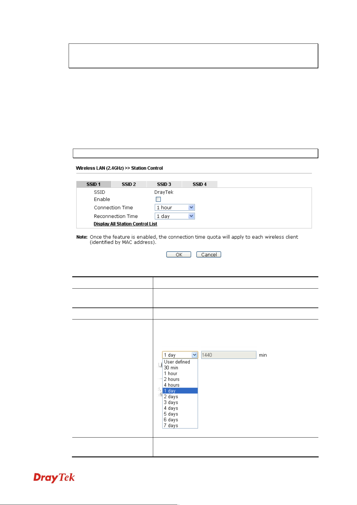
Note: Airtime Fairness function and Bandwidth Limit function should be mutually
exclusive. So their webs have extra actions to ensure these two functions are not enabled
simultaneously.
33..55..1100 SSttaattiioonn CCoonnttrrooll
Station Control is used to specify the duration for the wireless client to connect and
reconnect VigorAP. If such function is not enabled, the wireless client can connect VigorAP
until it shuts down.
Such feature is especially useful for free Wi-Fi service. For example, a coffee shop offers
free Wi-Fi service for its guests for one hour every day. Then, the connection time can be set
as “1 hour” and reconnection time can be set as “1 day”. Thus, the guest can finish his job
within one hour and will not occupy the wireless network for a long time.
Note: Up to 300 Wireless Station records are supported by VigorAP.
Available settings are explained as follows:
Item Description
SSID
Display the SSID that the wireless station will use it to
connect with Vigor router.
Enable
Connection Time /
Reconnection Time
Check the box to enable the station control function.
Use the drop down list to choose the duration for the
wireless client connecting /reconnecting to Vigor router. Or,
type the duration manually when you choose User defined.
Display All Station
Control List
All the wireless stations connecting to Vigor router by using
such SSID will be listed on Station Control List.
69
VigorAP 910C User’s Guide
Page 78

After finishing all the settings here, please click OK to save the configuration.
33..55..1111 RRooaammiinngg
The network signal for a single wireless access point might be limited by its coverage range.
Therefore, if you want to expand the wireless network in a large exhibition with a quick
method, you can install multiple access points with enabling the Roaming feature for each
AP to reach the purpose of expanding wireless signals seamlessly.
These access points connecting for each other shall be verified by pre-authentication. This
page allows you to enable the roaming feature and the pre-authentication.
Available settings are explained as follows:
Item Description
AP-assisted Client
Roaming Parameters
When the link rate of wireless station is too low or the signal
received by the wireless station is too worse, VigorAP 910C will
automatically detect (based on the link rate and RSSI
requirement) and cut off the network connection for that wireless
station to assist it to connect another Wireless AP to get better
signal.
Minimum Basic Rate – Check the box to use the drop down list
to specify a basic rate (Mbps). When the link rate of the wireless
station is below such value, VigorAP 910C will terminate the
network connection for that wireless station.
Disable RSSI Requirement - If it is selected, VigorAP will not
terminate the network connection based on RSSI.
Strictly Minimum RSSI - VigorAP uses RSSI (received signal
strength indicator) to decide to terminate the network connection
of wireless station. When the signal strength is below the value
(dBm) set here, VigorAP 910C will terminate the network
connection for that wireless station.
Minimum RSSI - When the signal strength of the wireless
station is below the value (dBm) set here and adjacent AP (must
be DrayTek AP and support such feature too) with higher signal
strength value (defined in the field of With Adjacent AP RSSI
over) is detected by VigorAP 910C, VigorAP 910C will
terminate the network connection for that wireless station. Later,
VigorAP 910C User’s Guide
70
Page 79

the wireless station can connect to the adjacent AP (with better
RSSI).
With Adjacent AP RSSI over – Specify a value as a
threshold.
Fast Roaming
(WPA/802.1x)
Enable – Check the box to enable fast roaming configuration.
PMK Cache Period - Set the expire time of WPA2 PMK
(Pairwise master key) cache. PMK Cache manages the list from
the BSSIDs in the associated SSID with which it has
pre-authenticated. Such feature is available for WPA2/802.1
mode.
Pre-Authentication - Enables a station to authenticate to
multiple APs for roaming securer and faster. With the
pre-authentication procedure defined in IEEE 802.11i
specification, the pre-four-way-handshake can reduce handoff
delay perceivable by a mobile node. It makes roaming faster and
more secure. (Only valid in WPA2)
Enable - Enable IEEE 802.1X Pre-Authentication.
Disable - Disable IEEE 802.1X Pre-Authentication.
After finishing this web page configuration, please click OK to save the settings.
71
VigorAP 910C User’s Guide
Page 80

33..55..1122 BBaanndd SStteeeerriinngg
Band Steering detects if the wireless clients are capable of 5GHz operation, and steers them
to that frequency. It helps to leave 2.4GHz band available for legacy clients, and improves
users experience by reducing channel utilization.
If dual-band is detected, the AP will let the wireless client connect to less congested wireless
LAN, such as 5GHz to prevent from network congestion.
Note: To make Band Steering work successfully, SSID and security on 2.4GHz also
MUST be broadcasted on 5GHz.
VigorAP 910C User’s Guide
72
Page 81

Open Wireless LAN (2.4GHz)>>Band Steering to get the following web page:
Available settings are explained as follows:
Item Description
Enable Band Steering
If it is enabled, VigorAP will detect if the wireless client is
capable of dual-band or not within the time limit.
Check Time…. – If the wireless station does not have the
capability of 5GHz network connection, the system shall
wait and check for several seconds (15 seconds, in default)
to make the 2.4GHz network connection. Specify the time
limit for VigorAP to detect the wireless client.
5GHz Minimum RSSI – The wireless station has the
capability of 5GHz network connection, yet the signal
performance might not be satisfied. Therefore, when the
signal strength is below the value set here while the
wireless station connecting to VigorAP, VigorAP will allow
the client to connect to 2.4GHz network.
After finishing this web page configuration, please click OK to save the settings.
73
VigorAP 910C User’s Guide
Page 82

Below shows how Band Steering works.
HHooww ttoo UUssee BBaanndd SStteeeerriinngg??
1. Open Wireless LAN(2.4GHz)>>Band Steering.
2. Check the box of Enable Band Steering and use the default value (15) for check time
setting.
3. Click OK to save the settings.
VigorAP 910C User’s Guide
74
Page 83

4. Open Wireless LAN (2.4GHz)>>General Setup and Wireless LAN (5GHz)>>
General Setup. Configure SSID as ap910C-BandSteering for both pages. Click OK to
save the settings.
Same value
for 2.4GHz
and 5GHz
75
VigorAP 910C User’s Guide
Page 84

Same value
for 2.4GHz
and 5GHz
5. Open Wireless LAN (2.4GHz)>>Security and Wireless LAN (5GHz)>>Security.
Configure Security as 12345678 for both pages. Click OK to save the settings.
6. Now, VigorAP 910C will let the wireless clients connect to less congested wireless LAN,
such as 5GHz to prevent from network congestion.
VigorAP 910C User’s Guide
76
Page 85

33..55..1133 SSttaattiioonn LLiisstt
Station List provides the knowledge of connecting wireless clients now along with its status code.
General
Display general information (e.g., MAC Address, SSID, Auth, Encrypt, TX/RX Rate) for the
station.
Available settings are explained as follows:
Item Description
MAC Address
SSID
Auth
Display the MAC Address for the connecting client.
Display the SSID that the wireless client connects to.
Display the authentication that the wireless client uses for
connection with such AP.
Encrypt
Tx Rate/Rx Rate
Refresh
Add to Access
Control
Display the encryption mode used by the wireless client.
Display the transmission /receiving rate for packets.
Click this button to refresh the status of station list.
Client’s MAC Address - For additional security of wireless
access, the Access Control facility allows you to restrict the
network access right by controlling the wireless LAN MAC
address of client. Only the valid MAC address that has been
configured can access the wireless LAN interface.
Add
Click this button to add current typed MAC address into Access
Control.
77
VigorAP 910C User’s Guide
Page 86

Advanced
Display more information (e.g., AID, PSM, WMM, RSSI PhMd, BW, MCS, Rate) for the
station.
Control
Display connection and reconnection time of the wireless stations.
Neighbor
Display more information for the neighboring wireless stations.
VigorAP 910C User’s Guide
78
Page 87

Wireless LAN ((22..44GGHHzz)) Settings for Station-Infrastructure
33..66
Mode
When you choose Station-Infrastructure as the operation mode, the Wireless LAN menu
items will include General Setup, Site Surv ey, Stat isti cs and WPS.
33..66..11 GGeenneerraall SSeettuupp
By clicking the General Setup, a new web page will appear so that you could configure the wireless profile and choose proper mode. Pl ea se refer to the foll owing figure for mor e information.
Available settings are explained as follows:
Item Description
Enable Wireless LAN
Mode
Add
Delete
Edit
Connect
Check the box to enable wireless function.
At present, VigorAP 910C can connect to 11 b only, 11 g only,
11 n only, Mixed (11b+11g), Mixed (11b+11g+11n) and Mixed
(11g+11n) stations simultaneously. Simply choose
(11b+11g+11n) mode.
Click this button to add new wireless profiles.
Click this button to delete the selected wireless profile.
Click this button to modify the existing wireless profile.
Click this button to connect the wireless station to AP with the
selected profile.
79
Mixed
VigorAP 910C User’s Guide
Page 88

Packet-OVERDRI
VE
This feature can enhance the performance in data transmission
about 40%* more (by che ck ing Tx B urs t). It is active only when
both sides of Access Point and Station (in wireless
this function at the same time. That is, the
support this feature and invoke the
wireless client must
function, too.
Note: Vigor N61 wireless adapter supports this function.
Therefore, you can use and install it into your PC for matching
with Packet-OVERDRIVE (refer to the following picture of
Vigor N61 wireless utility window, choose Enable for
client) invoke
TxBURST on the tab of Option).
MAC Clone
Check this box and manually enter the MAC address for
Station
mode driver.
After finishing this web page configuration, please click OK to save the settings.
AAdddd aa NNeeww WWiirreelleessss PPrrooffiillee
To add a new wireless profile for the stations, click Add. The following dialog box will
appear.
VigorAP 910C User’s Guide
80
Page 89

Available settings are explained as follows:
Item Description
Profile Name
SSID
Type a name for the new profile.
Type the name for such access point that can be used for
connection by the stations.
Network Type
Infrastructure - In this mode, you can connect the access
point to Ethernet device such as TV and Game player to
enable
the Ethernet device as a wireless station and join to a
wireless
network through an access point or AP router.
802.11 Ad Hoc – An ad-hoc network is a network where
wireless stations can communicate with peer to peer (P2P).
Power Saving Mode
Choose the power saving mode for such device.
CAM – Choose this item if it is not necessary to perform
81
VigorAP 910C User’s Guide
Page 90

power saving job.
Power Saving Mode – Choose this item to get into the power
saving status when there is no data passing through the access
point.
RTS Threshold
Set the RTS threshold of wireless radio. Do not m odif y default
value if you don’t know what it is, default value is 2347.
Fragment Threshold
Security Mode
Set the Fragment threshold of wireless radio. Do not modify
default value if you don’t know what it is, default value is
2346.
802.11 standard defines two mechanisms for authentication of
wireless LAN clients: Open Authentication and Shared Key
Authentication.
Choose one of the security modes from the drop down list. If
you choose OPEN or SHARED, you have to type WEP
information.
OPEN – Open authentication is basically null authentication
algorithm, which mea ns that there is no verification of the
user.
SHARED – It works simi lar to Open authentication with onl y
one major difference. If you choose OPEN with WEP
encryption key, the WEP keys is used to encrypt and decrypt
the data but not for authentication. In Shared key
authentication, WEP encryption will be used for
authentication.
WEP
If you choose WPA-Personal or WPA2-Personal, the
corresponding WPA settings will be listed as follows. You
have to choose the WPA algorithms and type the pass phrase
for such security mode.
WPA Algorithms – Choose Temporal Key Integ rity P rotocol
(TKIP) or AES for data encryption.
Pass Phrase – Please type 8 to 63 alphanumerical characters
here.
WEP Key Length - WEP (Wired Equivalent Privacy) is a
common encryption mo de. It is safe enough for hom e and
personal use. However, if you need higher level of security,
please consider using WPA encryption (see next section).
Some wireless clients do not support WPA, but support WEP.
Therefore WEP is still a good choice for you if you have such
kind of client in your networ k env ironm ent.
WEP Key Entry Method - There are two types of WEP key
VigorAP 910C User’s Guide
82
Page 91

length: 64-bit and 128-bit. Using 128-bit is safer than 64-bit,
but it will reduce some data transfer performance.
There are two types of key method: ASCII and Hex. When
you
select a key format, the number of characters of key will
be
displayed. For example, if you select 64-bit as key length,
and
Hex as key format, you’ll see the message at the right of
Key
Format is ‘Hex (10 characters) which means the length of
WEP key is 10 characters.
WEP Keys (Key 1 – Key 4) - Four keys can be entered here,
but only one key can be selected at a time. The format of WEP
Key is restricted to 5 ASCII characters or 10 hexadecimal
values in 64-bit encryption level, or restricted to 13 ASCII
characters or 26 hexadecimal values in 128-bit encryption
level. The allowed content is the ASCII characters from 33(!)
to 126(~) except '#' and ','. Such feature is available for WEP
mode.
Default Key – Choose one of the key sett ing s.
Below shows an example for a wireless profile created.
83
VigorAP 910C User’s Guide
Page 92

33..66..22 SSiittee SSuurrvveeyy
The page will list the access points nearby as VigorAP 910C is set to Station mode. You can
select one of the access points to associate.
Available settings are explained as follows:
Item Description
SSID
BSSID
RSSI
Display the SSID name of the access point.
Display the BSSID (MAC Address) of the access point.
Display the signal strength of the access point. RSSI is the
abbreviation of Receive Signal Strength Indication.
Channel
Encryption
Display the channel number of the access point.
Display the encryption setting of the access points. If you have
selected the access point with security setting, you have to go
to 2-7 Wireless Security to set the same security with the
access point you want to associate.
Authentication
Scan/Rescan
Connect
Add Profile
Display the authentication type of the access point.
Search the stations connected to such access point.
Connect to the wireless AP that you choose.
The system will add a profile automatically for you t o connect
with the wireless AP that you choose.
VigorAP 910C User’s Guide
84
Page 93

33..66..33 SSttaattiissttiiccss
This page displays the statistics for data transmission and receiving between the access point
and the stations.
33..66..44 WWPPSS ((WWii--FFii PPrrootteecctteedd SSeettuupp))
Wi-Fi Protected Setup (WPS) is the simplest way to build connection between wireless
network clients and the access point. You don’t have to select encryption mode and input a
long encryption passphrase every time when you need to setup a wireless client. You only
have to press a button on wireless client and the access point, and the WPS will do the setup
for you.
VigorAP 910C supports two types of WPS: Push-Button Configurati on (PBC), and PIN code.
If you want to use PBC, you have to switch VigorAP 910C to WPS m ode and push a specific
button on the wireless client to start WPS mode. You can push Reset/WPS button of this
VigorAP 910C, or click PBC Start button in the web configuration interface to do this; if you
want to use PIN code, you have to provide the PIN code of the wireless client you wish to
connect to this access point and then switch the wireless client to WPS mode.
Note: WPS function of VigorAP 910C will not work for those wireless AP/clients do not
support WPS.
To use WPS function to set encrypted connection between VigorAP 910C and WPS-enabled
wireless AP, please open Wireless LAN >>WPS. The following information will be
displayed:
85
VigorAP 910C User’s Guide
Page 94

Available settings are explained as follows:
Item Description
SSID
BSSID
RSSI
Display the SSID name of the access point.
Display the BSSID (MAC Address) of the access point.
Display the signal strength of the access point. RSSI is the
abbreviation of Receive Signal Strength Indication.
Ch. (Channel)
Auth.
Display the channel number of the access point.
Display the authentication type of the access point.
(Authentication)
Encrypt (Encryption)
Display the encryption setting of the access points. If you have
selected the access point with security setting, you have to go
to 2-7 Wireless Security to set the same security with the
access point you want to associate.
Ver. (Version)
Status
Refresh
Display the version of WPS.
Display the status of WPS access point.
Click this button to refresh the AP site survey.
Start PBC
Start PIN
Renew PIN
VigorAP 910C User’s Guide
Click Start PBC to make a WPS connec tion within 2 minutes.
When using PinCode method, it is required to enter PIN Code
(Personal Identification Number Code, 8-digit numbe rs) into
Registrar. When the wireless station is Enrollee, the users can
use Renew PIN to re-generate a new PIN code.
Click this button to re-genera te a new PIN code.
86
Page 95
Note: When you’re using PBC type WP S setup, you m ust press PBC button (hardware or
software) of wireless client within 2 minutes. If you didn’t press PBC button of wireless
client within this time period, please press PBC button (hardware or software) of this
access point again.
33..77 WWiirreelleessss LLAANN ((22..44GGHHzz)) SSeettttiinnggss ffoorr AAPP BBrriiddggee--PPooiinntt ttoo
PPooiinntt//AAPP BBrriiddggee--PPooiinntt ttoo MMuullttii--PPooiinntt MMooddee
When you choose AP Bridge-Point to Point or Point-to Multi-Point Mode as the operation
mode, the Wireless LAN menu items will include General Setup, AP Discovery, WDS AP
Status and Roaming.
AP Bridge-Point to Point allows VigorAP 910C to connect to another VigorAP 910C which
uses the same mode. All wired Ethernet clients of both VigorAP 910Cs will be connected
together.
Point-to Multi-Point Mode allows VigorAP 910C to connect up to four VigorAP 910Cs
which uses the same mode. All wired Ethernet clients of every VigorAP 910C will be
connected together.
33..77..11 GGeenneerraall SSeettuupp
By clicking the General Setup, a new web page will appear so that you could configure the PHY Mode, security, Tx Burst and choose proper mode. Please refer to the following figure for more information.
87
VigorAP 910C User’s Guide
Page 96

Available settings are explained as follows:
Item Description
Enable Wireless LAN
Mode
Check the box to enable wireless function.
At present, VigorAP 910C can connect to 11b only, 11g only,
11n only, Mixed (11b+11g), Mixed (11g+11n) and Mixed
(11b+11g+11n) stations simultaneously. Simply choose Mixed
(11b+11g+11n) mode.
Channel
Means the channel of frequency of the wireless LAN. The
default channel is 11. You may switch channel if the selected
channel is under serious interference. If you have no idea of
choosing the frequency, please select AutoSelect to let system
determine for you.
VigorAP 910C User’s Guide
88
Page 97

Extension Channel
With 802.11n, there is one option to double the bandwidth per
channel. The available extension channel options will be varied
according to the Channel selected above.
PHY Mode
Security
HTMIX (11b/g/n mixed mode) is specified VigorAP 910C.
Select WEP, TKIP or AES as the encryption algorithm. Type the
key number if required. Or click Disabled to ignore such feature.
Peer Mac Address
Type the peer MAC address for the access point that VigorAP
910C connects to.
After finishing this web page configuration, please click OK to save the settings.
89
VigorAP 910C User’s Guide
Page 98

33..77..22 AAddvvaanncceedd SSeettttiinngg
This page is to determine which algorithm will be selected for wireless transmission rate.
Available settings are explained as follows:
Item Description
Channel Width
20 MHZ- the device will use 20MHz for data transmission and
receiving between the AP and the stations.
Auto 20/40 MHZ – VigorAP will scan for nearby wireless AP
to determine which channel width (20MHz or 40MHz) shall be
used to meet the air situation. Usually, 40MHz would have
better performance under the clean wireless environment (e.g.,
less wireless traffic / contention). When the air condition is not
satisfied (e.g., dirty air), 20MHz will be used by VigorAP
automatically to ensure smooth network transmission.
40 MHZ- the device will use 40MHz for data transmission and
receiving between the AP and the stations.
Packet-OVERDRIVE
This feature can enhance the performance in data transmission
about 40%* more (by checking Tx Burst). It is active only
when both sides of Access Point and Station (in wireless
client) invoke this function at the same time. That is, the
wireless client must support this feature and invoke the
function, too.
VigorAP 910C User’s Guide
Note: Vigor N61 wireless adapter supports this function.
Therefore, you can use and install it into your PC for matching
with Packet-OVERDRIVE (refer to the following picture of
Vigor N61 wireless utility window, choose Enable for
TxBURST on the tab of Option).
90
Page 99

Antenna
Tx Power
Rate Adaptation
Algorithm
Fragment Length
RTS Threshold
Country Code
VigorAP 910C can be attached with two antennas to have good
data transmission via wireless connection. However, if you
have only one antenna attached, please choose 1T1R.
The default setting is the maximum (100%). Lower down the
value may degrade range and throughput of wireless.
Wireless transmission rate is adapted dynamically. Usually,
performance of “new” algorithm is better than “old”.
Set the Fragment threshold of wireless radio. Do not modify
default value if you don’t know what it is, default value is 2346.
Minimize the collision (unit is bytes) between hidden stations
to improve wireless performance.
Set the RTS threshold of wireless radio. Do not m odif y default
value if you don’t know what it is, default value is 2347.
VigorAP broadcasts country codes by following the 802.11d
standard. However, some wireless stations will detect / scan
the country code to prevent conflict occurred. If conflict is
detected, wireless station will be warned and is unable to make
network connection. Therefore, changing the country code to
ensure successful network connection will be necessary for
some clients.
Auto Channel
Reselect
Auto Channel
Filtered Out List
IGMP Snooping
Enable – Usually, wireless channel determined by AutoSelect
(Wireless LAN>>General Setup) means Vigor router will
search for a channel with low interference automatically once
the system reboots. However, when the channel utilization is
more than 70% (refer to Diagnostics >> Interference
Monitor), Vigor router will search for and switch another
channel with low interference to obtain better wireless signal
again.
The selected wireless channels will be discarded if AutoSelect
is selected as Channel selection mode in Wireless
LAN>>General Setup.
Check Enable to enable IGMP Snooping. Multicast traffic will
be forwarded to ports that have members of that group.
Disabling IGMP snooping will make multicast traffic treated in
91
VigorAP 910C User’s Guide
Page 100

the same manner as broadcast traffic.
Isolate 2.4GHz and
5GHz bands
Isolate members with
IP
MAC Clone
The default setting is “Enable”. It means that the wireless
client using 2.4GHz band is unable to connect to the wireless
client with 5GHz band, and vice versa.
For WLAN 2.4GHz and 5GHz set with the same SSID name:
No matter such function is enabled or disabled, clients
using WLAN 2.4GHz and 5GHz can communicate for
each other if Isolate Member (in Wireless
LAN>>General Setup) is NOT enabled for such SSID.
Yet, if the function of Isolate Member (in Wireless
LAN>>General Setup) is enabled for such SSID, clients
using WLAN 2.4GHz and 5GHz will be unable to
communicate with each other.
The default setting is “Disable”.
If it is enabled, VigorAP will isolate different wireless clients
according to their IP address(es).
Click Enable and manually enter the MAC address of the
device with SSID 1. The MAC address of other SSIDs will
change based on this MAC address.
VigorAP 910C User’s Guide
92
 Loading...