

Page 1

i
VigorAP 800 User’s Guide
Page 2

VigorAP 800 User’s Guide
ii
Page 3

VViiggoorrAAPP 880000
Wiirreelleessss AAcccceessss PPooiinntt
W
UUsseerr’’ss GGuuiiddee
Version: 1.51
Firmware Version: V1.1.0
Date: April 9, 2014
iii
VigorAP 800 User’s Guide
Page 4

Copyright Information
Copyright
Declarations
Trademarks
Copyright© 2014 All rights reserved. This publication contains information that is
protected by copyright. No part may be reproduced, transmitted, transcribed, stored in a
retrieval system, or translated into any language without written permission from the
copyright holders.
The following trademarks are used in this document:
Microsoft is a registered trademark of Microsoft Corp.
Windows, Windows 95, 98, Me, NT, 2000, XP, Vista and Explorer are
trademarks of Microsoft Corp.
Apple and Mac OS are registered trademarks of Apple Inc.
Other products may be trademarks or registered trademarks of their respective
manufacturers.
Safety Instructions and Approval
Safety
Instructions
Warranty
Read the installation guide thoroughly before you set up the modem.
The modem is a complicated electronic unit that may be repaired only be
authorized and qualified personnel. Do not try to open or repair the modem
yourself.
Do not place the modem in a damp or humid place, e.g. a bathroom.
The modem should be used in a sheltered area, within a temperature range of +5
to +40 Celsius.
Do not expose the modem to direct sunlight or other heat sources. The housing
and electronic components may be damaged by direct sunlight or heat sources.
Do not deploy the cable for LAN connection outdoor to prevent electronic shock
hazards.
Keep the package out of reach of children.
When you want to dispose of the modem, please follow local regulations on
conservation of the environment.
We warrant to the original end user (purchaser) that the modem will be free from any
defects in workmanship or materials for a period of one (1) year from the date of
purchase from the dealer. Please keep your purchase receipt in a safe place as it serves
as proof of date of purchase. During the warranty period, and upon proof of purchase,
should the product have indications of failure due to faulty workmanship and/or
materials, we will, at our discretion, repair or replace the defective products or
components, without charge for either parts or labor, to whatever extent we deem
necessary tore-store the product to proper operating condition. Any replacement will
consist of a new or re-manufactured functionally equivalent product of equal value, and
will be offered solely at our discretion. This warranty will not apply if the product is
modified, misused, tampered with, damaged by an act of God, or subjected to abnormal
working conditions. The warranty does not cover the bundled or licensed software of
other vendors. Defects which do not significantly affect the usability of the product will
not be covered by the warranty. We reserve the right to re vi se the ma nual and onli ne
documentation and to make changes from time to time in the contents hereof without
obligation to notify any person of such revision or changes.
Be a Registered
Owner
Firmware & Tools
Updates
VigorAP 800 User’s Guide
Web registration is preferred. You can register your Vigor modem via
http://www.draytek.com.
Due to the continuous evolution of DrayTek technology, all modems will be regularly
upgraded. Please consult the DrayTek web site for more information on newest
firmware, tools and documents.
http://www.draytek.com
iv
Page 5

European Community Declarations
Manufacturer: DrayTek Corp.
Address: No. 26, Fu Shing Road, Hukou Township, Hsinchu Industrial Park, Hsinchu County, Taiwan 303
Product: VigorAP 800
DrayTek Corp. declares that VigorAP 800 is in compliance with the following essential requirements and other
relevant provisions of R&TTE Directive 1999/5/EEC.
The product conforms to the requirements of Electro-Magnetic Compatibility (EMC) Directive 2004/108/EC by
complying with the requirements set forth in EN55022/Class B and EN55024/Class B.
The product conforms to the requirements of Low Voltage (LVD) Directive 2006/95/EC by complying with the
requirements set forth in EN60950-1.
Federal Communication Commission Interference Statement
This equipment has been tested and found to comply with the limits for a Class B digital device, pursuant to Part
15 of the FCC Rules. These limits are designed to provide reasonable protection against harmful interference in a
residential installation. This equipment generates, uses and can radiate radio frequency energy and, if not installed
and used in accordance with the instructions, may cause harmful interference to radio communications. However,
there is no guarantee that interference will not occur in a particular installation. If this equipment does cause
harmful interference to radio or televisi o n recept i on , whi ch can be determined by turning the equipment of f and
on, the user is encouraged to try to correct the interference by one of the following measures:
Reorient or relocate the receiving antenna.
Increase the separation between the equipment and receiver.
Connect the equipment into an outlet on a circuit different from that to which the receiver is connected.
Consult the dealer or an experienced radio/TV technician for help.
This device complies with Part 15 of the FCC Rules. Operation is subject to the following two conditions:
(1) This device may not cause harmful interference, and
(2) This device may accept any interference received, including interference that may cause undesired operation.
This product is designed for 2.4GHz WLAN network throughout the EC region and Switzerland with restrictions
in France.
You are cautioned that changes or modifications not expressly approved by the party responsible for compliance
could void your authority to operate the equipment.
FCC RF Radiation Exposure Statement
1. This Transmitter must not be co-located or operating in conjunction with any other antenna or transmitter.
2. This equipment complies with FCC RF radiation exposure limits set forth for an uncontrolled environment.
This equipment should be installed and operated with a minimum distance of 20 centimeters between the
radiator and your body.
v
VigorAP 800 User’s Guide
Page 6

VigorAP 800 User’s Guide
vi
Page 7

TTaabbllee ooff CCoonntteennttss
Preface.........................................................................................................1
1.1 Introduction ............................................................................................................................. 1
1.2 LED Indicators and Connectors.............................................................................................. 2
1.3 Hardware Installation .............................................................................................................. 4
1.3.1 Wired Connection for PC in LAN...................................................................................... 4
1.3.2 Wired Connection for Notebook in WLAN........................................................................ 5
1.3.2 Wireless Connection......................................................................................................... 6
1.3.3 POE Connection............................................................................................................... 7
Network Configuration................................................................................9
2.1 Windows 95/98/Me IP Address Setup..................................................................................... 9
2.2 Windows 2000 IP Address Setup...........................................................................................11
2.3 Windows XP IP Address Setup............................................................................................. 12
2.4 Windows Vista IP Address Setup.......................................................................................... 13
2.5 Accessing to Web User Interface.......................................................................................... 14
2.6 Changing Password.............................................................................................................. 15
2.7 Quick Start Wizard................................................................................................................ 16
2.7.1 Configuring 2.4G Wireless Settings – General............................................................... 16
2.7.2 Configuring 2.4G Wireless Settings based on the Operation Mode............................... 18
2.7.3 Configuring 5G Wireless Settings................................................................................... 25
2.7.4 Configuring 5G Security Settings ................................................................................... 27
2.7.5 Finishing the Wireless Settings Wizard.......................................................................... 29
2.8 Online St atus......................................................................................................................... 30
Advanced Configuration.................................................................................31
3.1 Operation Mode .................................................................................................................... 32
3.2 LAN .......................................................................................................................................33
3.3 General Concepts for Wireless LAN..................................................................................... 35
3.4 Wireless LAN Settings for AP Mode..................................................................................... 37
3.4.1 General Setup................................................................................................................. 37
3.4.2 Security........................................................................................................................... 42
3.4.3 Access Control................................................................................................................ 45
3.4.4 WPS................................................................................................................................ 46
3.4.5 AP Discovery.................................................................................................................. 47
3.4.6 WMM Configuration........................................................................................................ 48
3.4.7 Station List...................................................................................................................... 50
vii
VigorAP 800 User’s Guide
Page 8

3.4.8 Bandwidth Management................................................................................................. 51
3.5 Wireless LAN Settings for Station-Infrastructure Mode ........................................................ 52
3.5.1 General Setup................................................................................................................. 52
3.5.2 Site Survey ..................................................................................................................... 58
3.5.3 Statistics.......................................................................................................................... 59
3.5.4 WPS (Wi-Fi Protected Setup)......................................................................................... 59
3.6 Wireless LAN Settings for AP Bridge-Point to Point/AP Bridge-Point to Multi-Point Mode .. 61
3.6.1 General Setup................................................................................................................. 62
3.6.2 AP Discovery.................................................................................................................. 65
3.6.3 WDS AP Status .............................................................................................................. 66
3.7 Wireless LAN Settings for AP Bridge-WDS Mode ................................................................ 66
3.7.1 General Setup................................................................................................................. 67
3.7.2 Security........................................................................................................................... 71
3.7.3 Access Control................................................................................................................ 74
3.7.4 WPS................................................................................................................................ 75
3.7.5 AP Discovery.................................................................................................................. 76
3.7.6 WDS AP Status .............................................................................................................. 77
3.7.7 WMM Configuration........................................................................................................ 77
3.7.8 Station List...................................................................................................................... 78
3.7.9 Bandwidth Management................................................................................................. 79
3.8 Wireless LAN Settings for Universal Repeater Mode........................................................... 80
3.8.1 General Setup................................................................................................................. 81
3.8.2 Security........................................................................................................................... 85
3.8.3 Access Control................................................................................................................ 88
3.8.4 WPS................................................................................................................................ 90
3.8.5 AP Discovery.................................................................................................................. 91
3.8.6 Universal Repeater......................................................................................................... 92
3.8.7 WMM Configuration........................................................................................................ 95
3.8.8 Station List...................................................................................................................... 97
3.8.9 Bandwidth Management................................................................................................. 98
3.9 Wireless LAN (5G) Settings for AP Mode ............................................................................. 99
3.9.1 General Setup................................................................................................................. 99
3.9.2 Security......................................................................................................................... 101
3.9.3 Access Control.............................................................................................................. 104
3.9.4 AP Discovery................................................................................................................ 105
3.9.5 Station List.................................................................................................................... 106
3.9.6 Bandwidth Management............................................................................................... 107
3.10 RADIUS Server................................................................................................................. 108
3.1 1 Applications....................................................................................................................... 109
3.11.1 Schedule..................................................................................................................... 109
3.12 System Maintenance..........................................................................................................111
3.12.1 System Status............................................................................................................. 111
3.12.2 TR-069........................................................................................................................ 113
3.12.3 Administrator Password.............................................................................................. 115
3.12.4 Configuration Backup ................................................................................................. 116
3.12.5 Time and Date............................................................................................................ 117
3.12.6 Reboot System........................................................................................................... 118
3.12.7 Firmware Upgrade...................................................................................................... 119
3.13 Diagnostics.........................................................................................................................119
3.13.1 System Log................................................................................................................. 119
3.13.2 Speed Test ................................................................................................................. 120
VigorAP 800 User’s Guide
viii
Page 9

Application and Exampl es......................................................................121
4.1 How to set different segments for different SSIDs in VigorAP 800..................................... 121
Trouble Shooting.....................................................................................125
5.1 Checking If the Hardware Status Is OK or Not....................................................................125
5.2 Checking If the Network Connection Settings on Your Computer Is OK or Not ................. 126
5.3 Pinging the Modem from Your Computer............................................................................ 128
5.4 Backing to Factory Default Setting If Necessary ................................................................ 129
5.5 Contacting Your Dealer....................................................................................................... 130
ix
VigorAP 800 User’s Guide
Page 10

Page 11
Prreeffaaccee
P
11..11 IInnttrroodduuccttiioonn
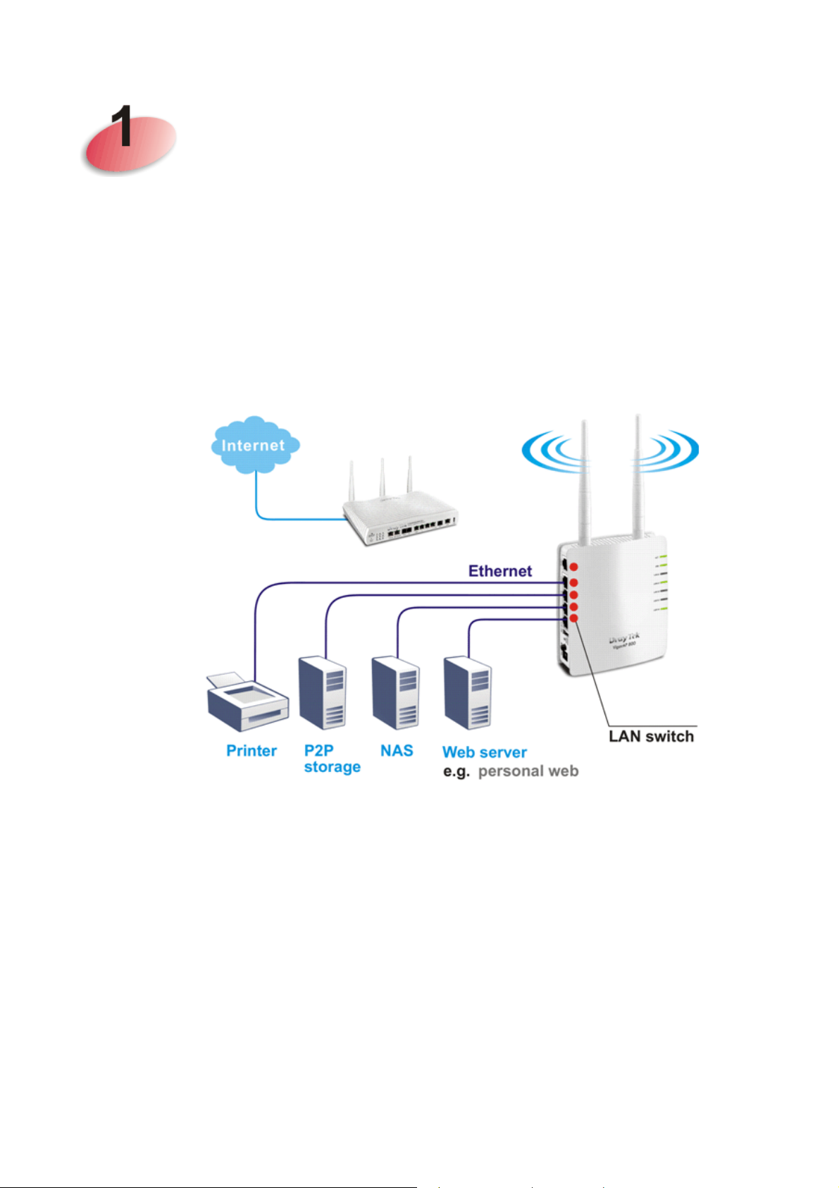
Thank you for purchasing this VigorAP 800! With this high cost-efficiency VigorAP 800,
computers and wireless devices which are compatible with 802.11n can connect to existing
wired Ethernet network via this VigorAP 800, at the speed of 300Mbps.
Easy install procedures allows any computer users to setup a network environment in very
short time - within minutes, even inexperienced users. Just follow the instructions given in
this user manual, you can complete the setup procedure and release the power of this access
point all by yourself!
1
VigorAP 800 User’s Guide
Page 12
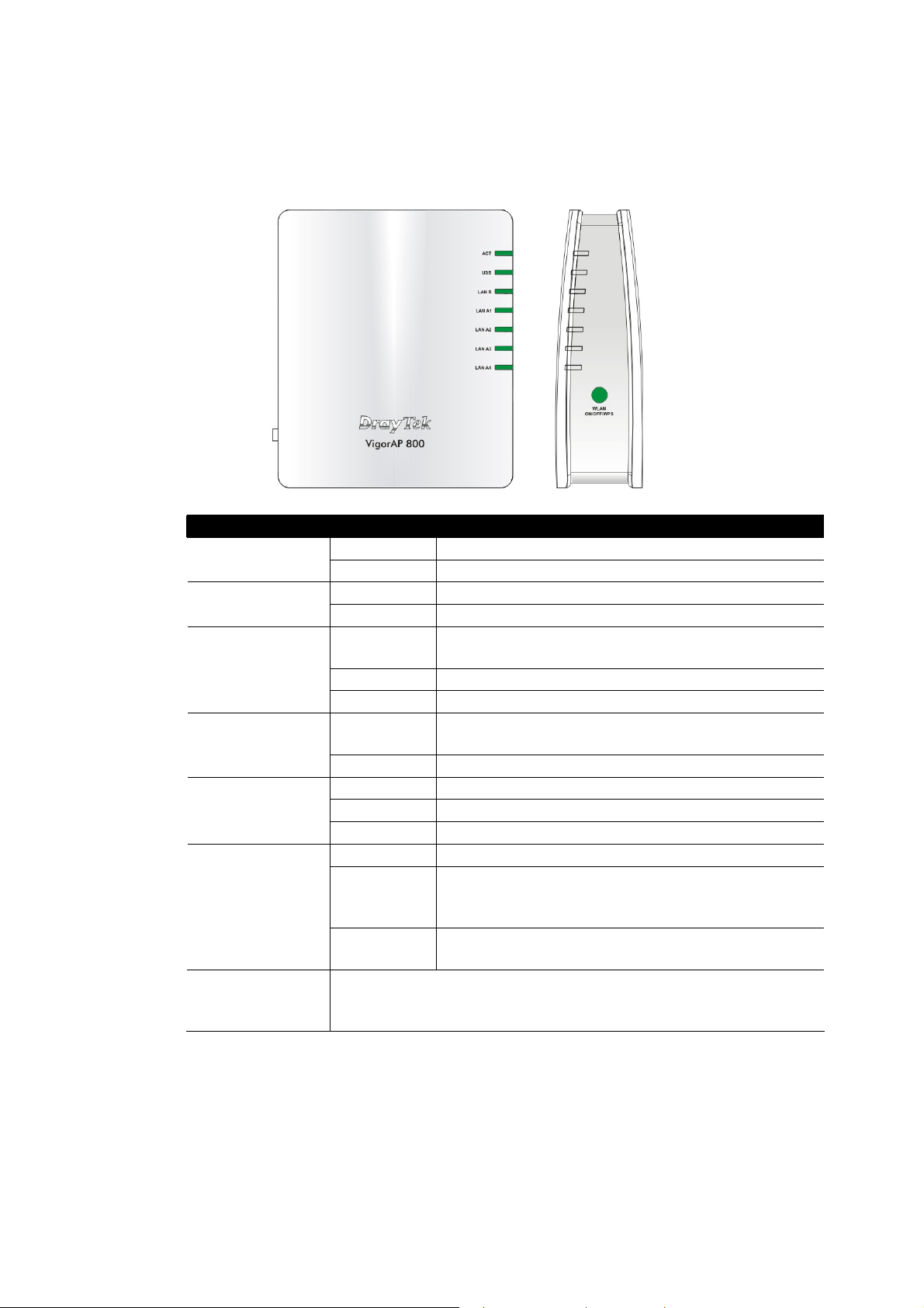
11..22 LLEEDD IInnddiiccaattoorrss aanndd CCoonnnneeccttoorrss
Before you use the Vigor modem, please get acquainted with the LED indicators and
connectors first.
LED Status Explanation
Off The system is not ready or is failed. ACT
Blinking The system is ready and can work normally.
On A USB device is connected and active. USB
Blinking The data is transmitting.
LAN B
LAN A1 - A4
WLAN
(Green LED) on
WLAN button
WPS
(Orange LED) on
WLAN button
WPS Button Press this button for 2 seconds to wait for client device making
On A normal connection is through its corresponding
port.
Off LAN is disconnected.
Blinking Data is transmitting (sending/receiving).
On A normal connection is through its corresponding
port.
Off LAN is disconnected.
On Wireless function is ready.
Off Wireless function is not ready.
Blinking Data is transmitting (sending/receiving).
Off The WPS is off.
Blinking
(Orange)
Blink with 1 second cycle for 2 minutes - - WPS is
enabled and waiting for wireless client to connect
with it.
Blinking
Data is transmitting (sending/receiving).
(Orange)
network connection through WPS. When the orange LED lights up,
the WPS will be on.
VigorAP 800 User’s Guide
2
Page 13
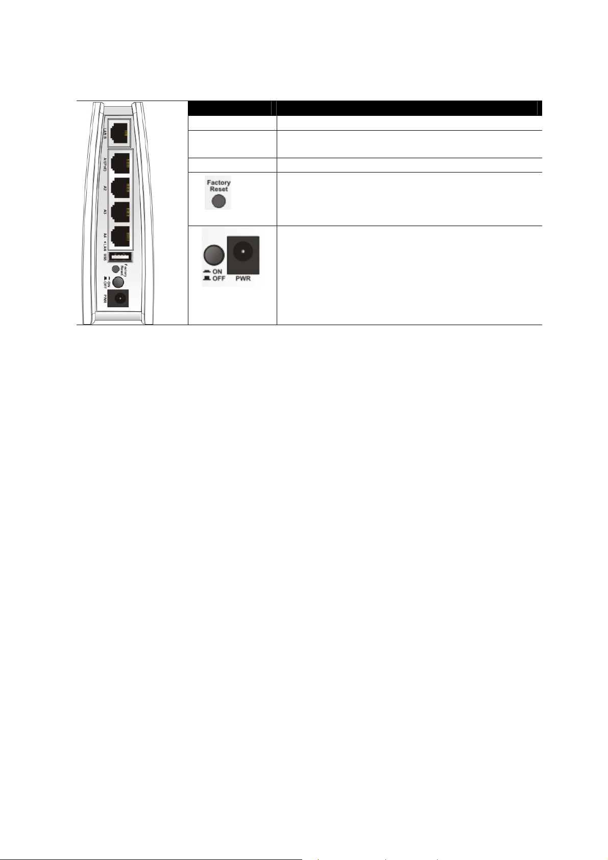
Interface Description
LAN B Connecter for xDSL / Cable modem or router.
LAN A1 (PoE) -
Connecter for xDSL / Cable modem or router.
A4
USB Connector for future use.
Restore the default settings. Usage: Turn on VigorAP
800. Press the button and keep for more than 10
seconds. Then VigorAP 800 will restart with the
factory default configuration.
ON/OFF: Power switch.
PWR: Connecter for a power adapter.
3
VigorAP 800 User’s Guide
Page 14
11..33 HHaarrddwwaarree IInnssttaallllaattiioonn
This section will guide you to install the modem through hardware connection and configure
the modem’s settings through web browser.
Before starting to configure the modem, you have to connect your devices correctly.
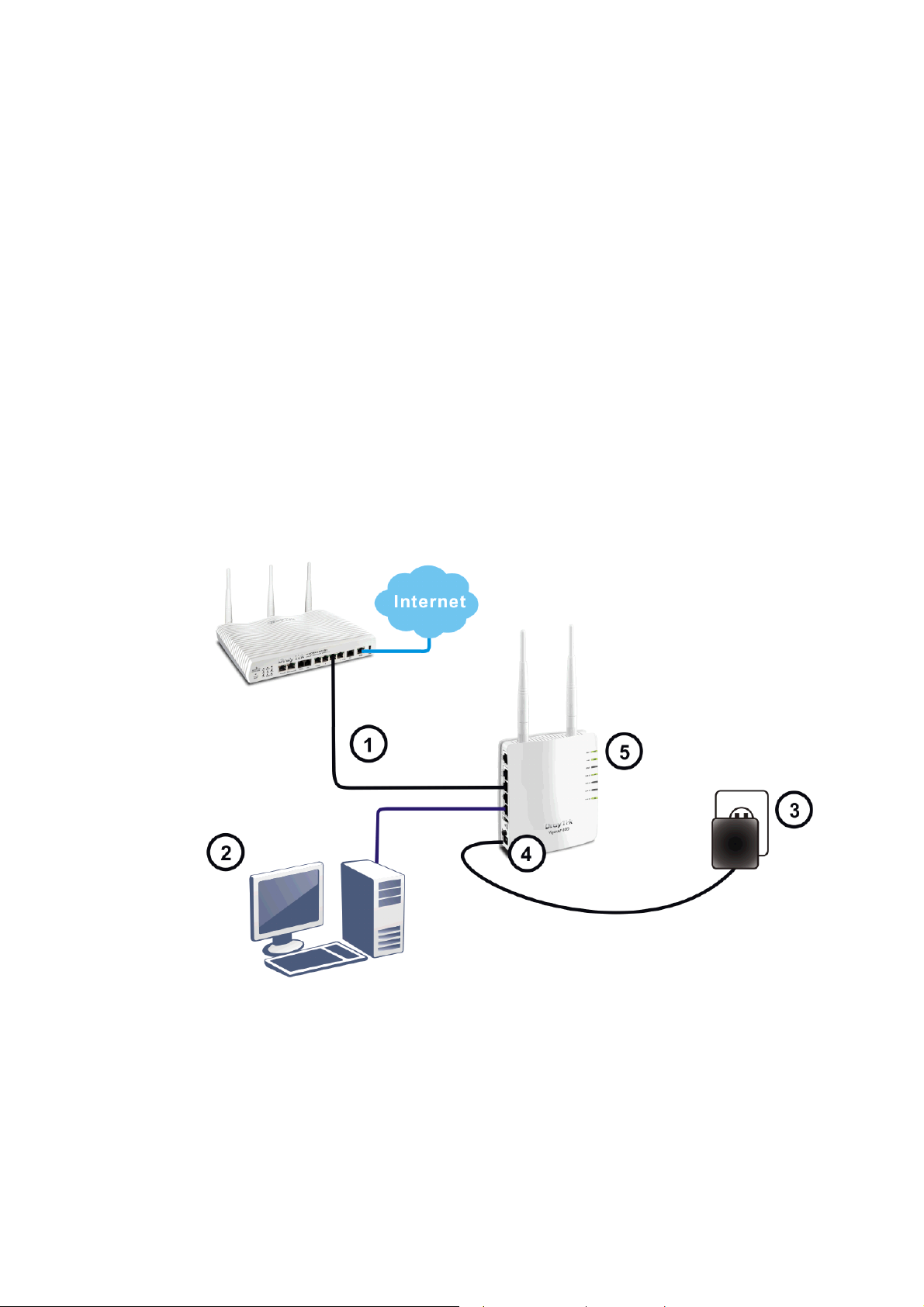
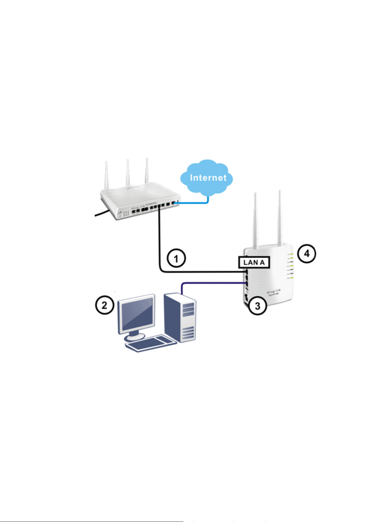
11..33..11 WWiirreedd CCoonnnneeccttiioonn ffoorr PPCC iinn LLAANN
1. Connect VigorAP 800 to ADSL modem, router, or switch/hub in your network through
the LAN A port of the access point by Ethernet cable.
2. Connect a computer to other available LAN A port. Make sure the subnet IP address of
the PC is the same as VigorAP 800 management IP, e.g., 192.168.1.X.
3. Connect the A/C power adapter to the wall socket, and then connect it to the PWR
connector of the access point.
4. Power on VigorAP 800.
5. Check all LEDs on the front panel. ACT LED should be steadily on, LAN LEDs
should be on if the access point is correctly connected to the ADSL modem or router.
(For the detailed information of LED status, please refer to section 1.2.)
VigorAP 800 User’s Guide
4
Page 15
11..33..22 WWiirreedd CCoonnnneeccttiioonn ffoorr NNootteebbooookk iinn WWLLAANN
1. Connect VigorAP 800 to ADSL modem or router in your network through the LAN A
port of the access point by Ethernet cable.
2. Connect the A/C power adapter to the wall socket, and then connect it to the PWR
connector of the access point.
3. Power on VigorAP 800.
4. Check all LEDs on the front panel. ACT LED should be steadily on, LAN LEDs
should be on if the access point is correctly connected to the ADSL modem or router.
(For the detailed information of LED status, please refer to section 1.2.)
5
VigorAP 800 User’s Guide
Page 16
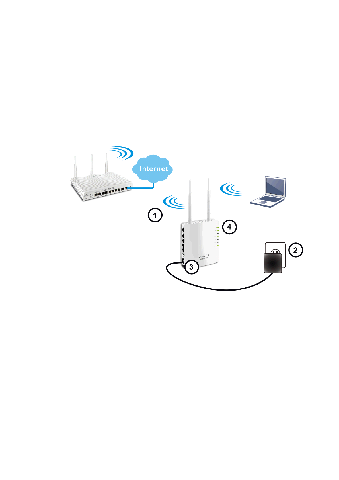
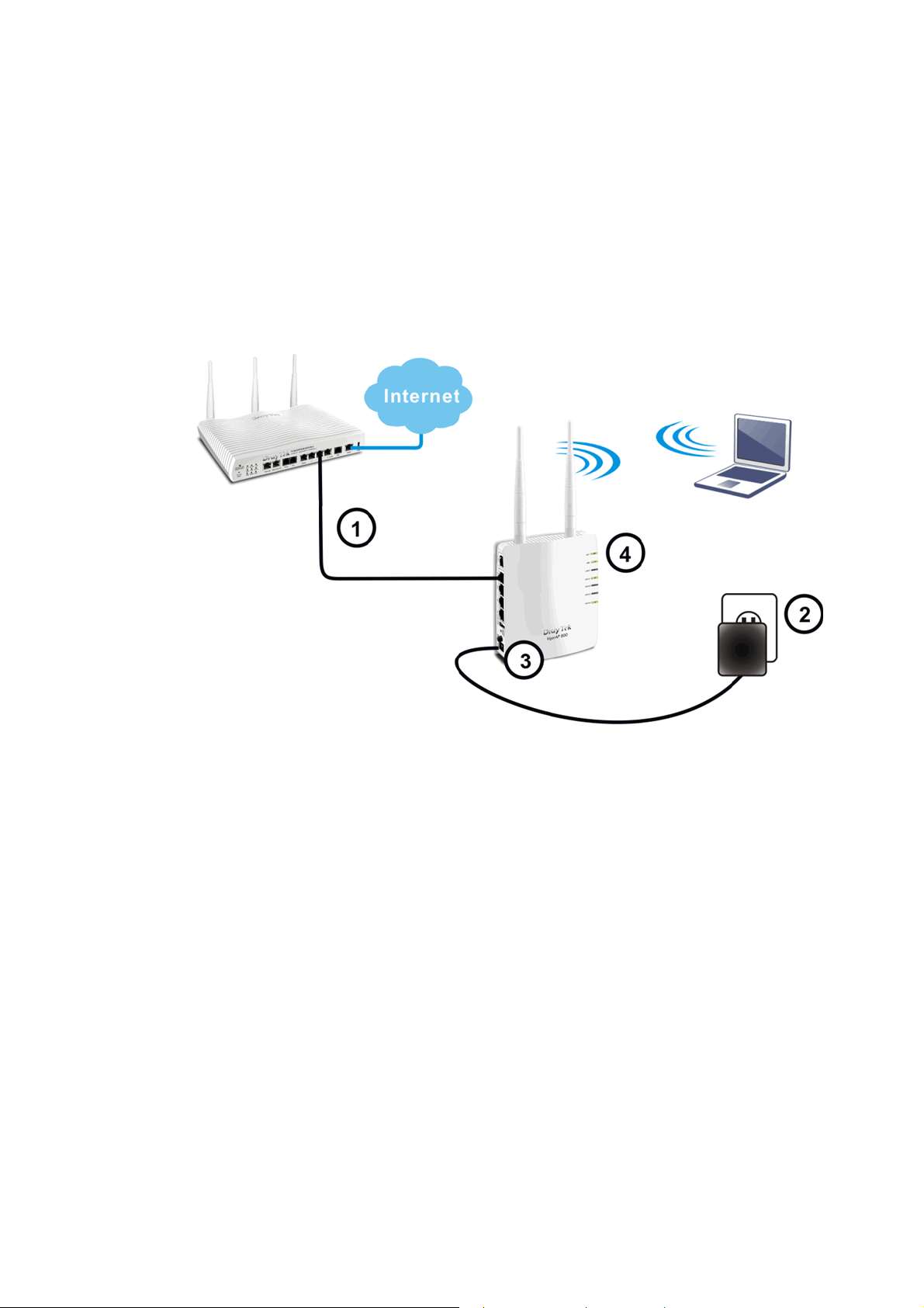
11..33..22 WWiirreelleessss CCoonnnneeccttiioonn
VigorAP 800 can access Internet via an ADSL modem, router, or switch/hub in your
network through wireless connection.
1. Connect VigorAP 800 to ADSL modem or router via wireless network.
2. Connect the A/C power adapter to the wall socket, and then connect it to the PWR
connector of the access point.
3. Power on VigorAP 800.
4. Check all LEDs on the front panel. ACT LED should be steadily on, LAN LEDs
should be on if VigorAP 800 is correctly connected to the ADSL modem, router or
switch/hub.
(For the detailed information of LED status, please refer to section 1.2.)
VigorAP 800 User’s Guide
6
Page 17
11..33..33 PPOOEE CCoonnnneeccttiioonn
VigorAP 800 can gain the power from the connected switch, e.g., VigorSwitch P2260. PoE
(Power over Ethernet) can break the install limitation caused by the fixed power supply.
1. Connect VigorAP 800 to a switch in your network through the LAN A1 port of the
access point by Ethernet cable.
2. Connect a computer to LAN A2 – A4. Make sure the subnet IP address of the PC is the
same as VigorAP 800 management IP, e.g., 192.168.1.X.
3. Power on VigorAP 800.
4. Check all LEDs on the front panel. ACT LED should be steadily on, LAN LEDs
should be on if the access point is correctly connected to the ADSL modem, router or
switch/hub.
7
VigorAP 800 User’s Guide
Page 18

This page is left blank.
VigorAP 800 User’s Guide
8
Page 19
Neett
N
After the network connection is built, the next step you should do is setup VigorAP 800 with
proper network parameters, so it can work properly in your network environment.
Before you can connect to the access point and start configuration procedures, your
computer must be able to get an IP address automatically (use dynamic IP address). If it’s set
to use static IP address, or you’re unsure, please follow the following instructions to
configure your computer to use dynamic IP address:
For the default IP address of this AP is set “192.168.1.2”, we recommend you to use
“192.168.1.X (except 2)” in the field of IP address on this section for your computer.
If the operating system of your computer is…
Windows 95/98/Me - please go to section 2.1
Windows 2000 - please go to section 2.2
Windows XP - please go to section 2.3
Windows Vista - please go to section 2.4
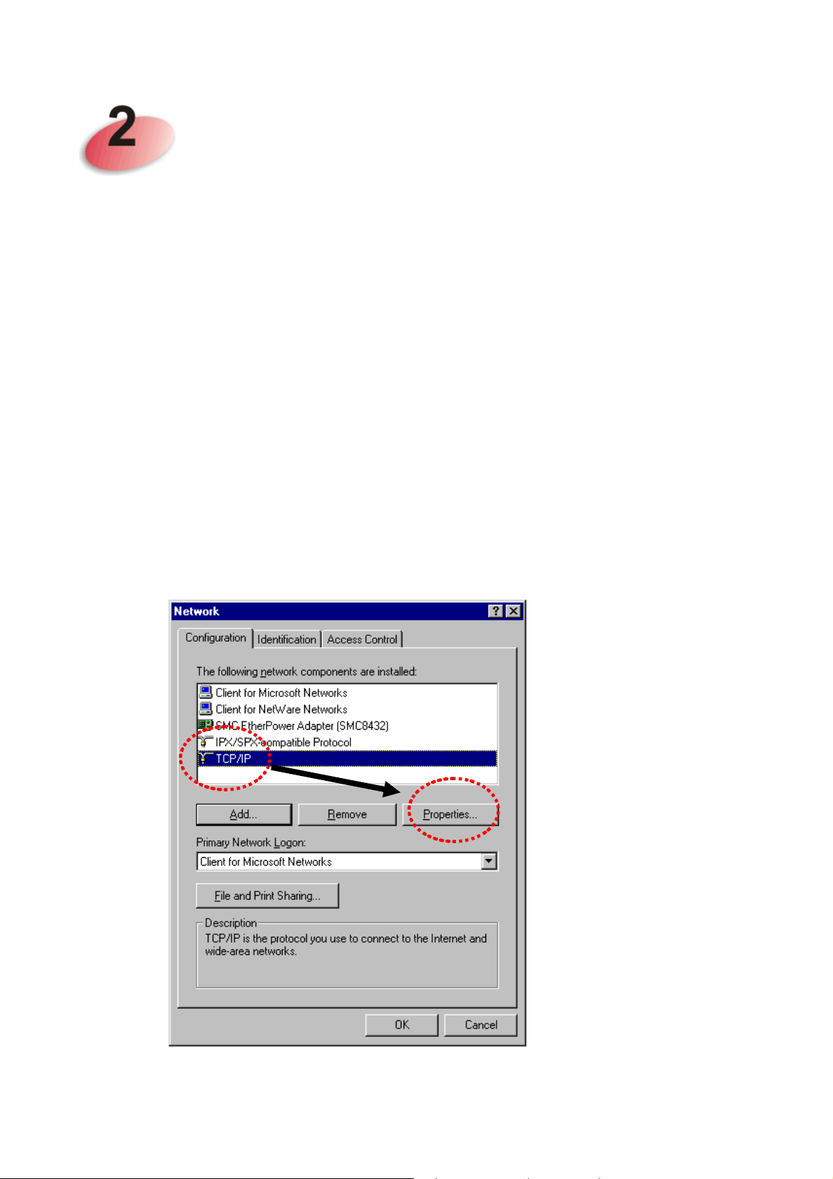
22..11 WWiinnddoowwss 9955//9988//MMee IIPP AAddddrreessss SSeettuupp
Click Start button (it should be located at lower-left corner of your computer), then click
control panel. Double-click Network icon, and the Network window will appear. Select
TCP/IP, then click ‘Properties’.
woorrkk
w
Coonnffiigguurraattiioonn
C
9
VigorAP 800 User’s Guide
Page 20
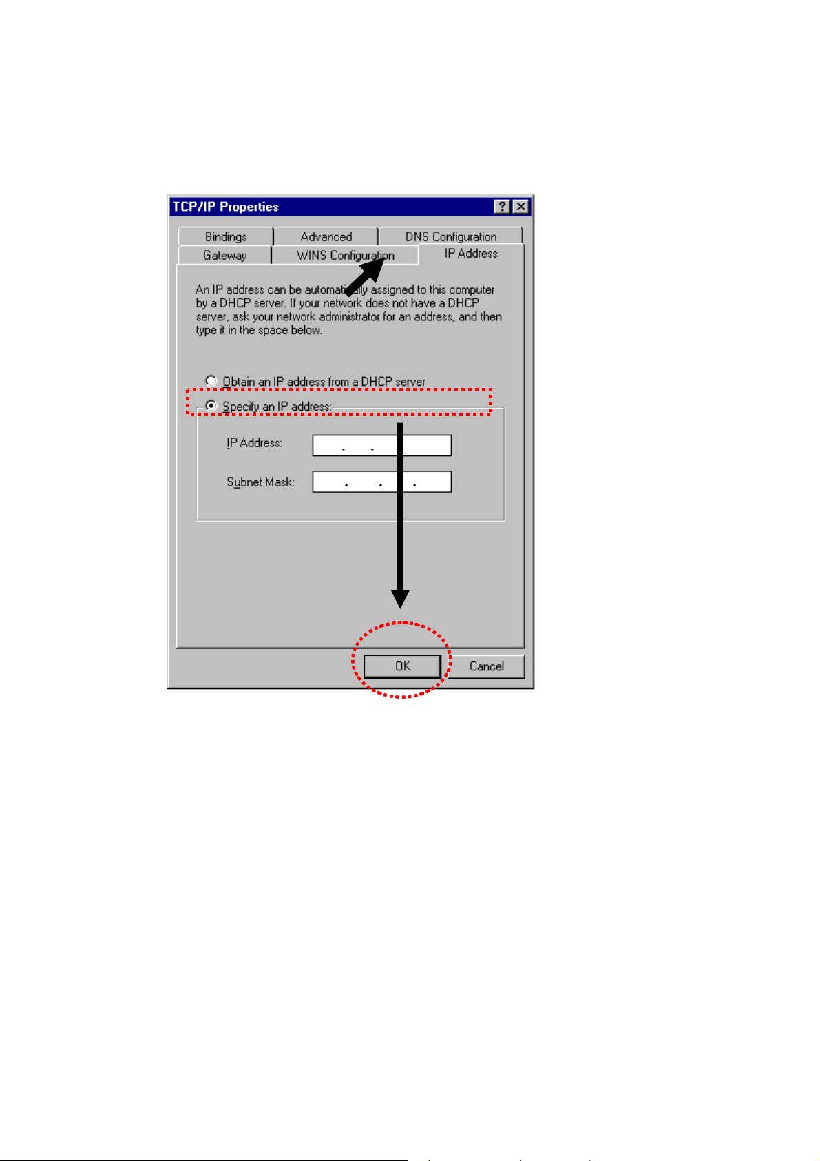
Select Specify an IP address, then input the following settings in respective field and click
OK when finish.
IP address: 192.168.1.9
Subnet Mask: 255.255.255.0
VigorAP 800 User’s Guide
10
Page 21
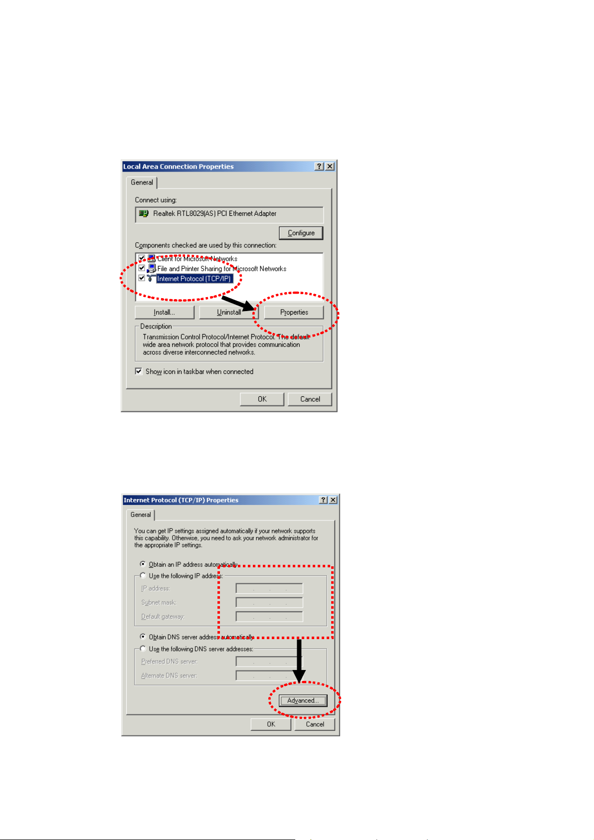
22..22 WWiinnddoowwss 22000000 IIPP AAddddrreessss SSeettuupp
Click Start button (it should be located at lower-left corner of your computer), then click
control panel. Double-click Network and Dial-up Connections icon, double click Local
Area Connection, and Local Area Connection Properties window will appear. Select
Internet Protocol (TCP/IP), then click Properties.
Select Use the following IP address, then input the following settings in respective field and
click OK when finish.
IP address: 192.168.1.9
Subnet Mask: 255.255.255.0
11
VigorAP 800 User’s Guide
Page 22
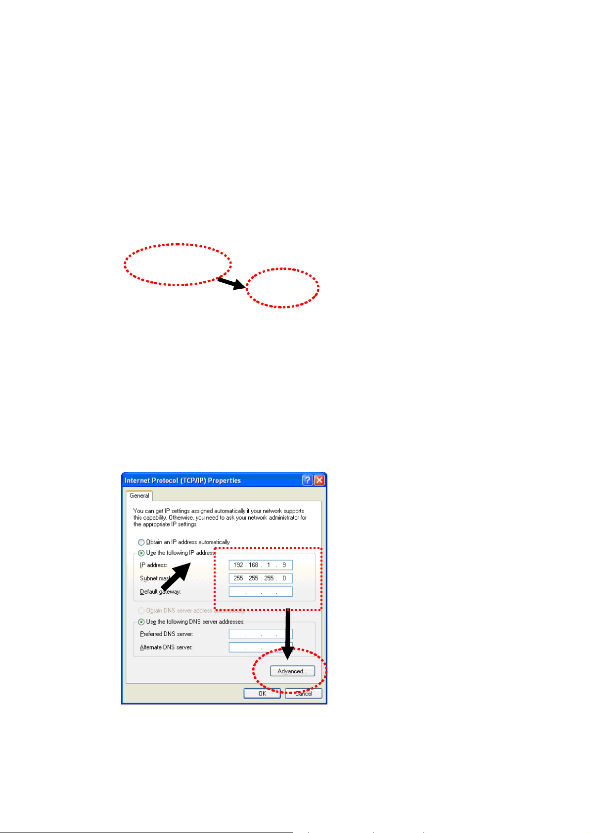
22..33 WWiinnddoowwss XXPP IIPP AAddddrreessss SSeettuupp
Click Start button (it should be located at lower-left corner of your computer), then click
control panel. Double-click Network and Internet Connections icon, click Network
Connections, and then double-click Local Area Connection, Local Area Connection
Status window will appear, and then click Properties.
Select Use the following IP address, then input the following settings in respective field and
click OK when finish:
IP address: 192.168.1.9
Subnet Mask: 255.255.255.0.
VigorAP 800 User’s Guide
12
Page 23
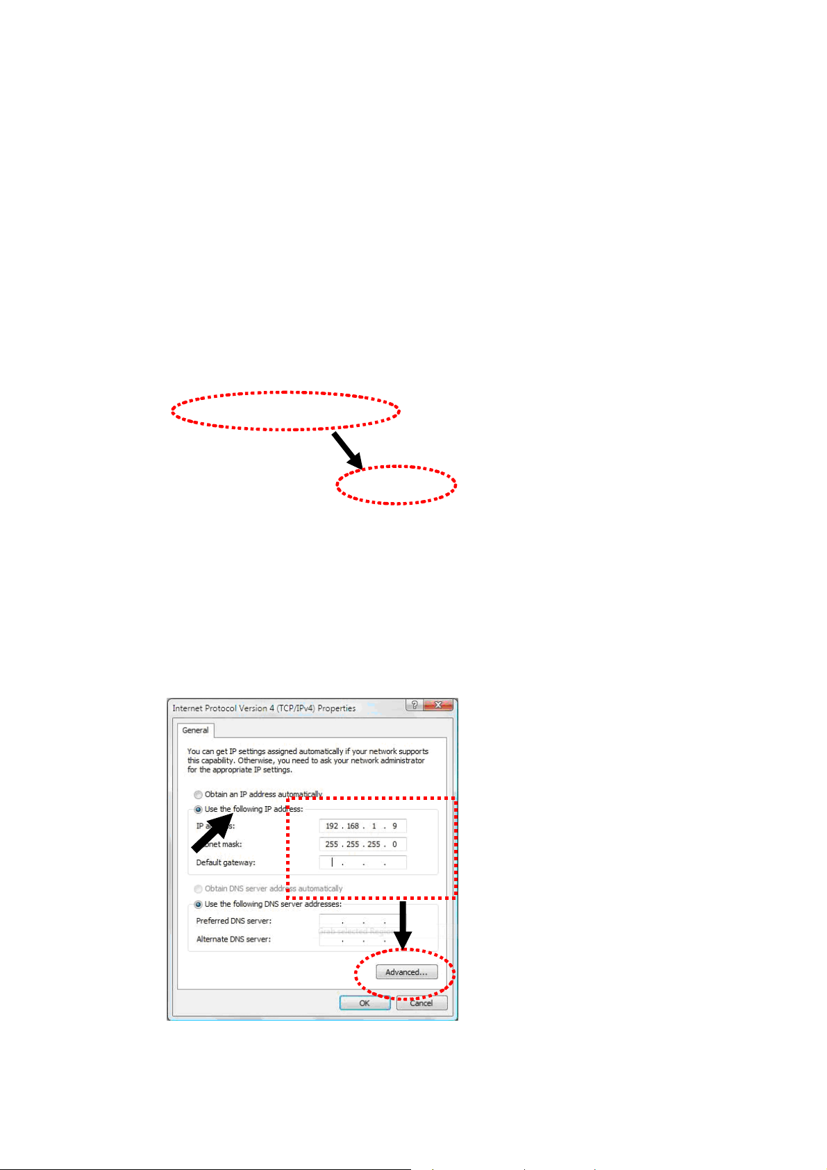
22..44 WWiinnddoowwss VViissttaa IIPP AAddddrreessss SSeettuupp
Click Start button (it should be located at lower-left corner of your computer), then click
control panel. Click View Network Status and Tasks, then click Manage Network
Connections. Right-click Local Area Netwrok, then select ‘Properties’. Local Area
Connection Properties window will appear, select Internet Protocol Version 4 (TCP /
IPv4), and then click Properties.
Select Use the following IP address, then input the following settings in respective field and
click OK when finish:
IP address: 192.168.1.9
Subnet Mask: 255.255.255.0.
13
VigorAP 800 User’s Guide
Page 24
22..55 AAcccceessssiinngg ttoo WWeebb UUsseerr IInntteerrffaaccee
All functions and settings of this access point must be configured via web user interface.
Please start your web browser (e.g., IE).
1. Make sure your PC connects to the VigorAP 800 correctly.
Notice: You may either set up your computer to get IP dynamically from the
router or set up the IP address of the computer to be in the same subnet as
the IP address of VigorAP800. If there is no DHCP server on the network, then
VigorAP800 will have an IP Address of 192.168.1.2. If DHCP is available, then
VigorAP800 will receive it's IP Address via DHCP, in this case to find the
VigorAP800 IP Address please check the DHCP server.
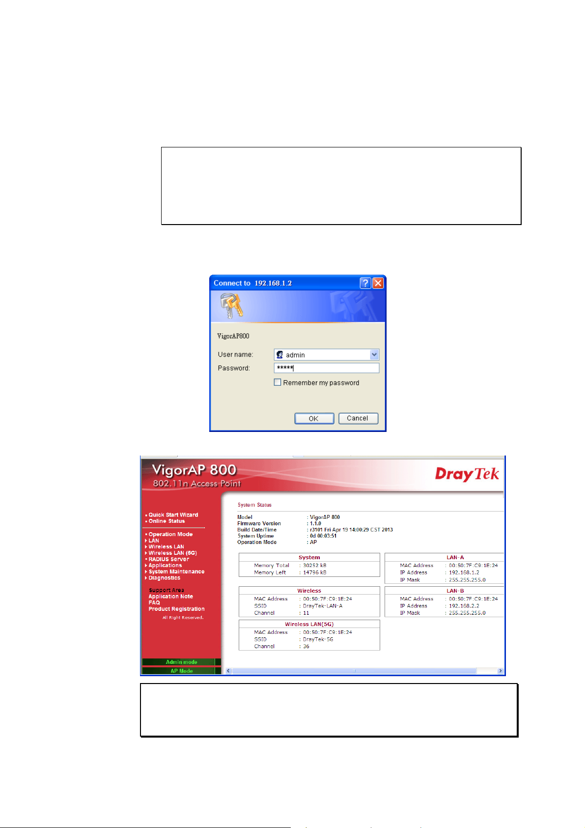
2. Open a web browser on your PC and type http://192.168.1.2. A pop-up window will
open to ask for username and password. Pease type “admin/admin” on
Username/Password and click OK.
3. The Main Screen will pop up.
If you fail to access to the web configuration, please go to “Trouble
Note:
Shooting” for detecting and solving your problem. For using the device properly, it
is necessary for you to change the password of web configuration for security and
adjust primary basic settings.
VigorAP 800 User’s Guide
14
Page 25
22..66 CChhaannggiinngg PPaasssswwoorrdd
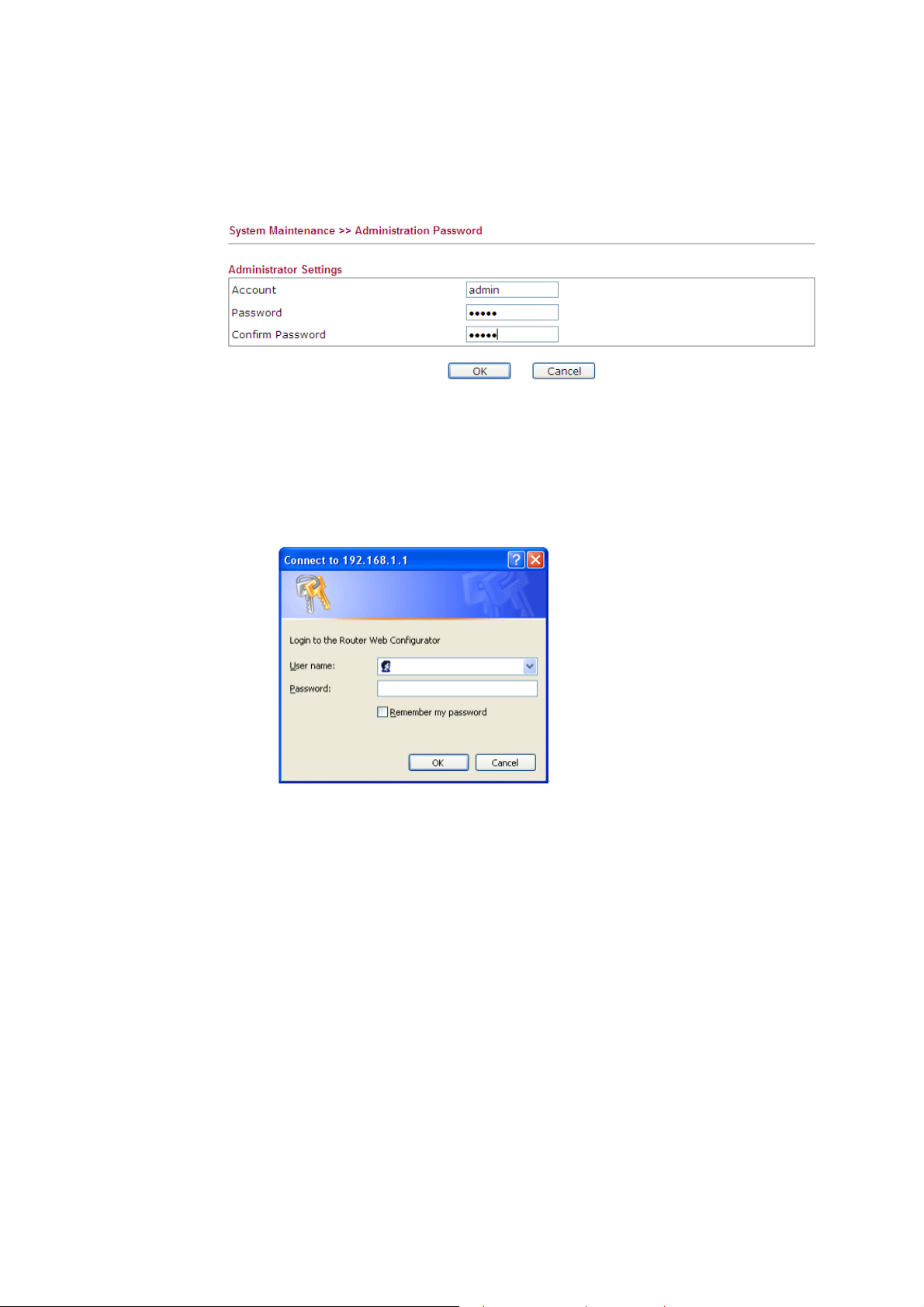
1. Please change the password for the original security of the modem.
2. Go to System Maintenance page and choose Administrator Password.
3. Enter the new login password on the field of Password and Confirm Password. Then
click OK to continue.
4. Now, the password has been changed. Next time, use the new password to access the
Web Configurator for this modem.
15
VigorAP 800 User’s Guide
Page 26
22..77 QQuuiicckk SSttaarrtt WWiizzaarrdd
Quick Start Wizard will guide you to configure 2.4G wireless setting, 5G wireless setting
and other corresponding settings for Vigor Access Point step by step.
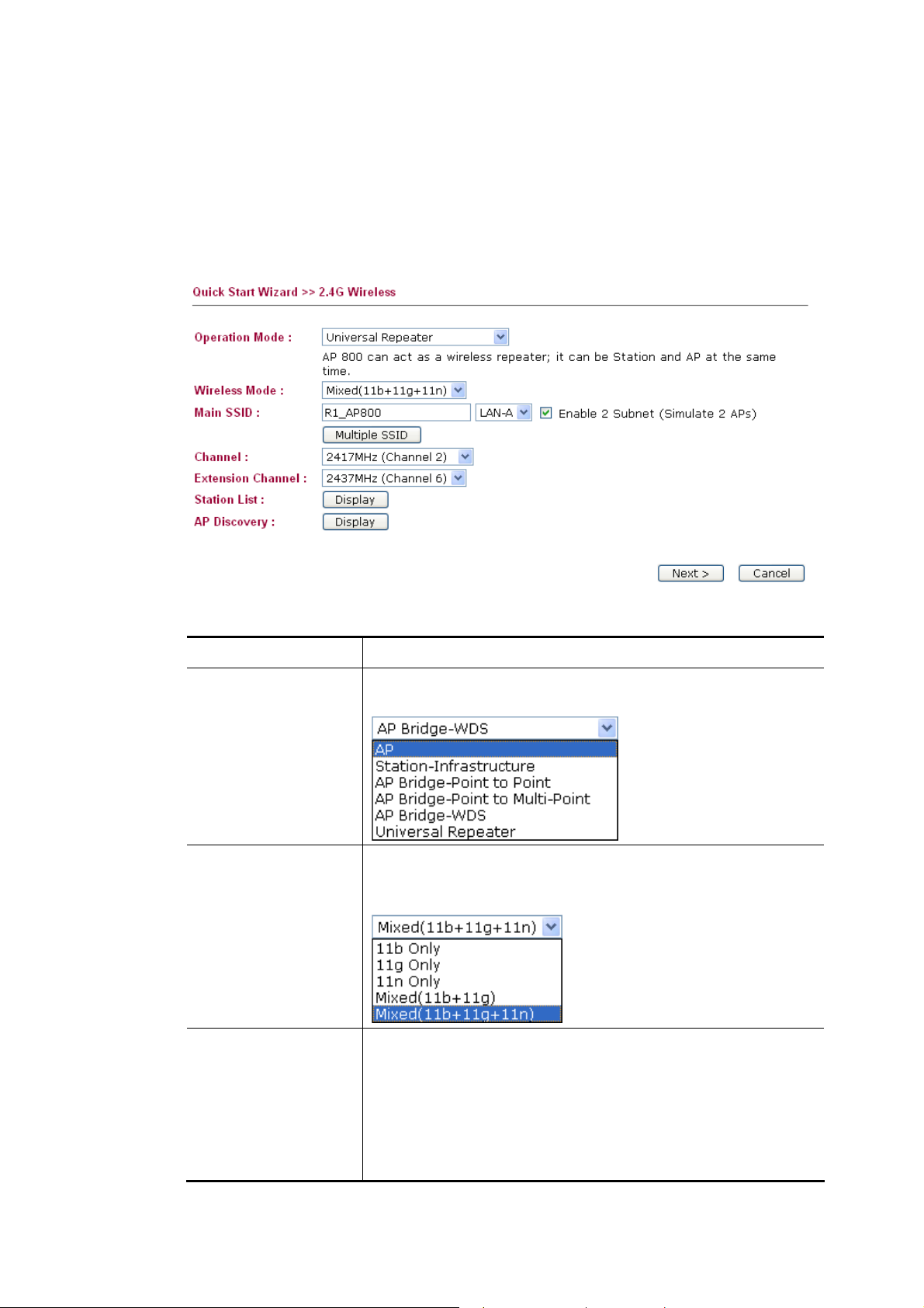
22..77..11 CCoonnffiigguurriinngg 22..44GG WWiirreelleessss SSeettttiinnggss –– GGeenneerraall
This page displays general settings for the operation mode selected.
Available settings are explained as follows:
Item Description
Operation Mode
Wireless Mode
Main SSID
There are six operation modes for wireless connection. Settings
for each mode are different.
At present, VigorAP 800 can connect to 11b only, 11g only, 11n
only, Mixed (11b+11g) and Mixed (11b+11g+11n) stations
simultaneously. Simply choose Mixed (11b+11g+11n) mode.
Set a name for VigorAP 800 to be identified.
Enable 2 Subnet (Simulate 2 APs) - Check the box to enable
the function for two independent subnets. Once you enable this
function, LAN-A and LAN-B would be independent. Next, you
can connect one router in LAN-A, and another router in LAN-B.
Such mechanism can make you feeling that you have two
independent AP/subnet functions in one VigorAP 800.
VigorAP 800 User’s Guide
16
Page 27
If you disable this function, LAN-A and LAN-B ports are in the
same domain. You could only connect one router (no matter
connecting to LAN-A or LAN-B) in this environment.
Multiple SSID - When Enable 2 Subnet is enabled, you can
specify subnet interface (LAN-A or LAN-B) for each SSID by
using the drop down menu.
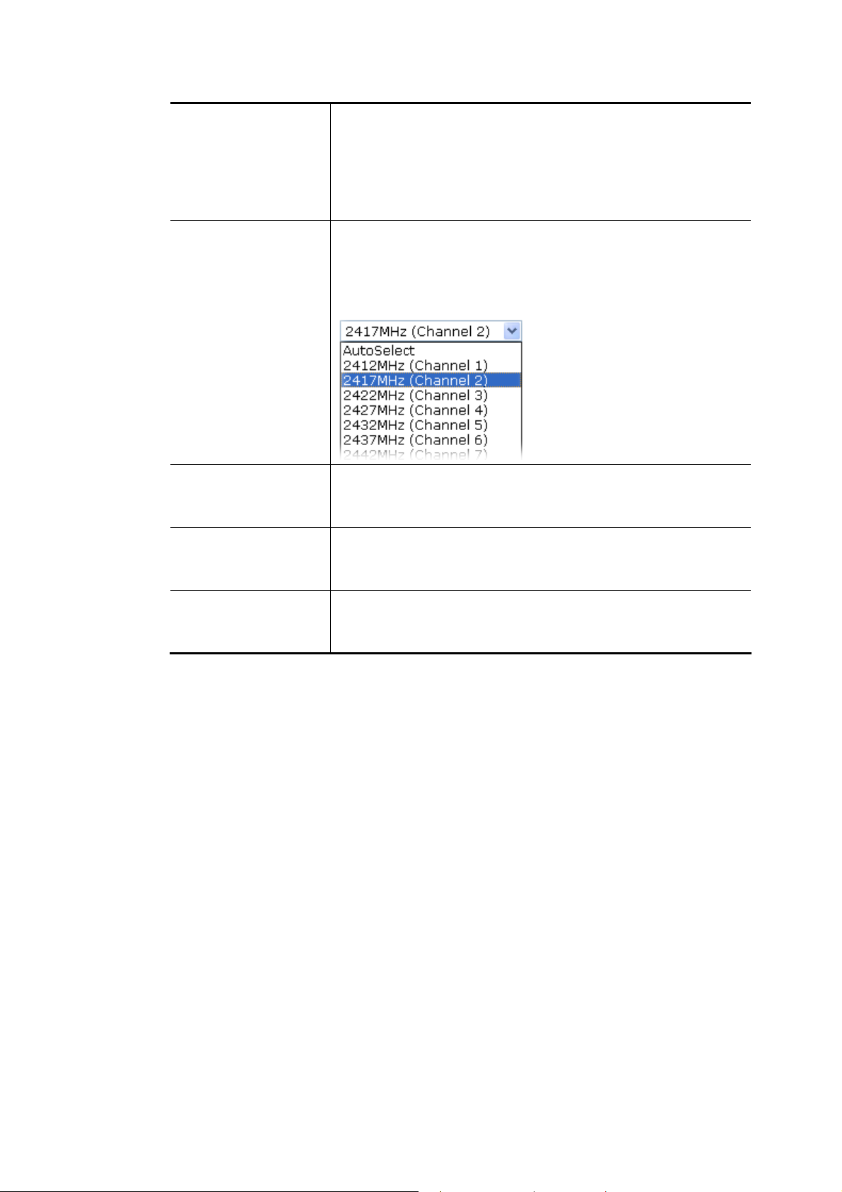
Channel
Extension Channel
Station List
AP Discovery
Means the channel frequency of the wireless LAN. The default
channel is 6. You may switch channel if the selected channel is
under serious interference. If you have no idea of choosing the
frequency, please select AutoSelect to let system determine for
you.
With 802.11n, there is one option to double the bandwidth per
channel. The available extension channel options will be varied
according to the Channel selected above.
Click this button to open the Station List dialog. It provides the
knowledge of connecting wireless clients now along with its
status code.
Click this button to open the AP Discovery dialog. VigorAP 800
can scan all regulatory channels and find working APs in the
neighborhood.
After finishing this web page configuration, please click Next to continue.
17
VigorAP 800 User’s Guide
Page 28
22..77..22 CCoonnffiigguurriinngg 22..44GG WWiirreelleessss SSeettttiinnggss bbaasseedd oonn t
In this page, the advanced settings will vary according to the operation mode chosen on
2.7.1.
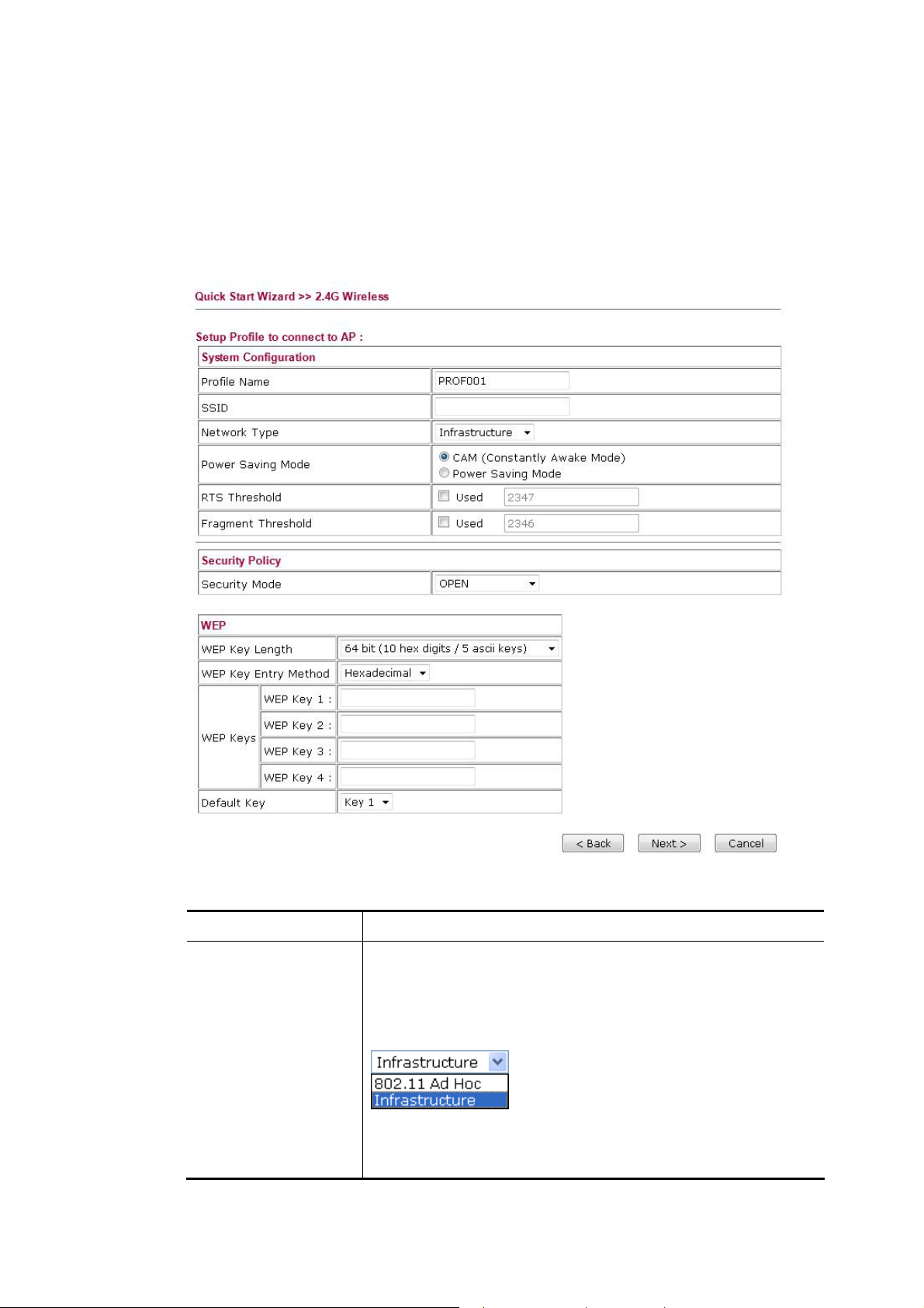
AAddvvaanncceedd SSeettttiinnggss ffoorr SSttaattiioonn--IInnffrraassttrruuccttuurree
When you choose Station-Infrastructure, you will need to configure the following page to
connect to one AP.
thhee OOppeerraattiioonn MMooddee
Available settings are explained as follows:
Item Description
System
Configuration
VigorAP 800 User’s Guide
Profile Name -Type a name for the new profile.
SSID - Type the name for such access point that can be used for
connection by the stations.
Network Type
Infrastructure - In this mode, you can connect the access
point to Ethernet device such as TV and Game player to
enable the Ethernet device as a wireless station and join to
18
Page 29
a wireless network through an access point or AP router.
802.11 Ad Hoc – An ad-hoc network is a network where
wireless stations can communicate with peer to peer (P2P).
Power Saving Mode - Choose the power saving mode for such
device.
CAM – Choose this item if it is not necessary to perform
power saving job.
Power Saving Mode – Choose this item to get into the
power saving status when there is no data passing through
the access point.
RTS Threshold- Set the RTS threshold of wireless radio. Do
not modify default value if you don’t know what it is, default
value is 2347.
Fragment Threshold - Set the Fragment threshold of wireless
radio. Do not modify default value if you don’t know what it is,
default value is 2346.
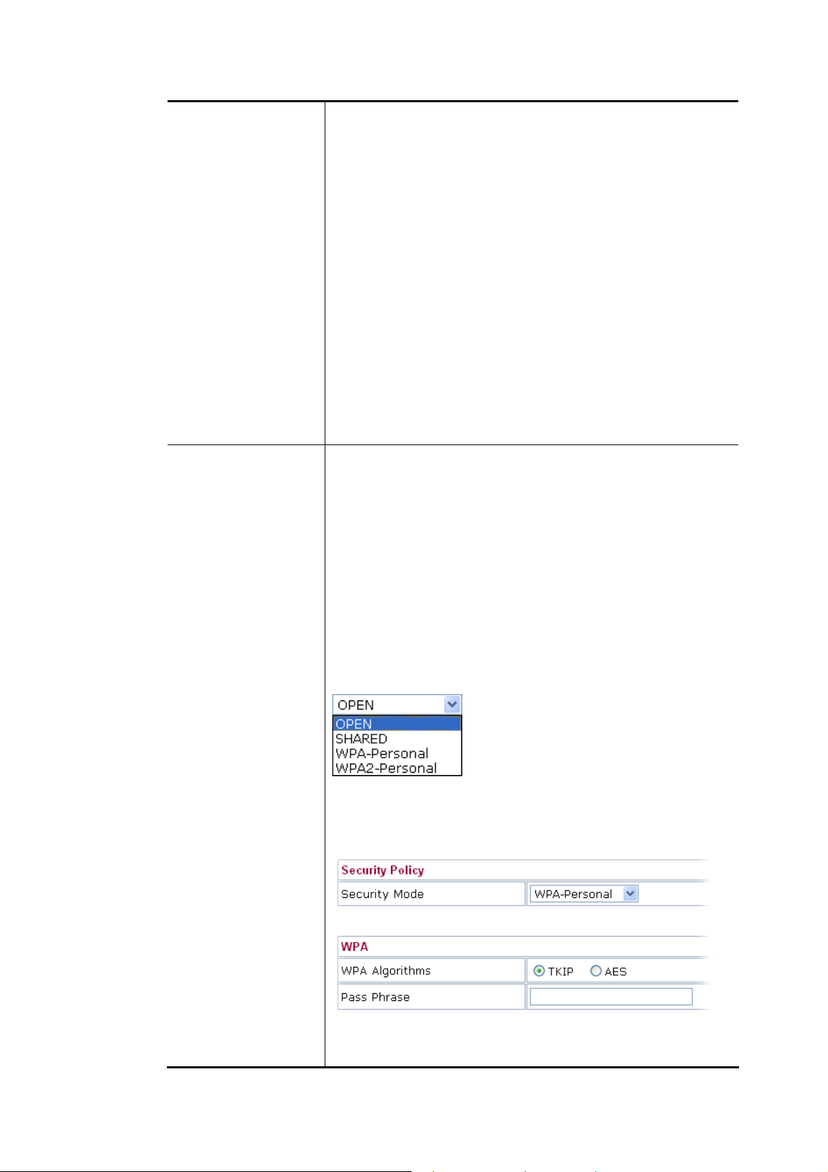
Security Mode
802.11 standard defines two mechanisms for authentication of
wireless LAN clients: Open Authentication and Shared Key
Authentication.
Choose one of the security modes from the drop down list. If
you choose OPEN or SHARED, you have to type WEP
information.
OPEN – Open authentication is basically null authentication
algorithm, which means that there is no verification of the user.
SHARED – It works similar to Open authentication with only
one major difference. If you choose OPEN with WEP encryption
key, the WEP keys is used to encrypt and decrypt the data but
not for authentication. In Shared key authentication, WEP
encryption will be used for authentication.
If you choose WPA-Personal or WPA2-Personal, the
corresponding WPA settings will be listed as follows. You have
to choose the WPA algorithms and type the pass phrase for such
security mode.
WPA Algorithms – Choose Temporal Key Integrity Protocol
(TKIP) or AES for data encryption.
19
VigorAP 800 User’s Guide
Page 30
Pass Phrase – Please type 8 to 63 alphanumerical characters
here.
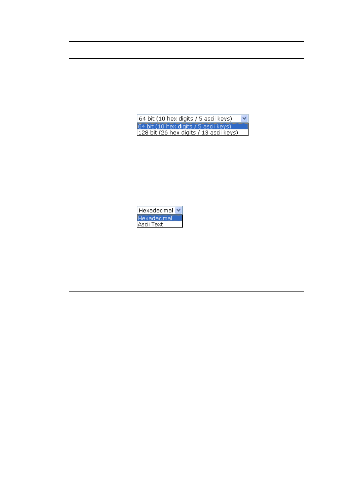
WEP
WEP Key Length - WEP (Wired Equivalent Privacy) is a
common encryption mode. It is safe enough for home and
personal use. However, if you need higher level of security,
please consider using WPA encryption (see next section).
Some wireless clients do not support WPA, but support WEP.
Therefore WEP is still a good choice for you if you have such
kind of client in your network environment.
WEP Key Entry Method - There are two types of WEP key
length: 64-bit and 128-bit. Using 128-bit is safer than 64-bit, but
it will reduce some data transfer performance.
There are two types of key method: ASCII and Hex. When you
select a key format, the number of characters of key will be
displayed. For example, if you select 64-bit as key length, and
Hex as key format, you’ll see the message at the right of Key
Format is ‘Hex (10 characters) which means the length of WEP
key is 10 characters.
WEP Keys (Key 1 – Key 4) - Four keys can be entered here, but
only one key can be selected at a time. The format of WEP Key
is restricted to 5 ASCII characters or 10 hexadecimal values in
64-bit encryption level, or restricted to 13 ASCII characters or
26 hexadecimal values in 128-bit encryption level. The allowed
content is the ASCII characters from 33(!) to 126(~) except '#'
and ','. Such feature is available for WEP mode.
Default Key – Choose one of the key settings.
VigorAP 800 User’s Guide
20
Page 31

AAddvvaanncceedd SSeettttiinnggss ffoorr AAPP BBrriiddggee--PPooiinntt ttoo PPooiinntt
When you choose AP Bridge-Point to Point, you will need to configure the following page.
Available settings are explained as follows:
Item Description
Phy Mode
There are three types of transmission rates developed by
different techniques for Phy Mode. Data will be transmitted via
communication channel.
Security
Peer MAC Address
Select CCK (11b mode), OFDM (11g mode), or HTMIX
(11b/g/n mixed mode) from the drop down menu for the access
point that VigorAP 800 wants to connect. Each access point
should be setup to the same Phy mode for connecting with each
other.
Select WEP, TKIP or AES as the encryption algorithm. Type the
key number if required.
Type the peer MAC address for the access point that VigorAP
800 connects to.
21
VigorAP 800 User’s Guide
Page 32

AAddvvaanncceedd SSeettttiinnggss ffoorr AAPP BBrriiddggee--PPooiinntt ttoo MMuullttii--PPooiinntt
When you choose AP Bridge-Point to Multi-Point, you will need to configure the following
page.
Available settings are explained as follows:
Item Description
Phy Mode
There are three types of transmission rates developed by
different techniques for Phy Mode. Data will be transmitted via
communication channel.
Select CCK (11b mode), OFDM (11g mode), or HTMIX
(11b/g/n mixed mode) from the drop down menu for the access
point that VigorAP 800 wants to connect. Each access point
should be setup to the same Phy mode for connecting with each
other.
Security
Select WEP, TKIP or AES as the encryption algorithm. Type the
key number if required.
Peer MAC Address
Type the peer MAC address for the access point that VigorAP
800 connects to.
VigorAP 800 User’s Guide
22
Page 33

AAddvvaanncceedd SSeettttiinnggss ffoorr AAPP BBrriiddggee--WWDDSS
When you choose AP Bridge-WDS, you will need to configure the following page.
Available settings are explained as follows:
Item Description
Phy Mode
There are three types of transmission rates developed by
different techniques for Phy Mode. Data will be transmitted via
communication channel.
Select CCK (11b mode), OFDM (11g mode), or HTMIX
(11b/g/n mixed mode) from the drop down menu for the access
point that VigorAP 800 wants to connect. Each access point
should be setup to the same Phy mode for connecting with each
other.
Subnet
Security
Choose LAN-A or LAN-B for each SSID.
Select WEP, TKIP or AES as the encryption algorithm. Type the
key number if required. Or, you can click Disable to disable the
function.
Peer MAC Address
Type the peer MAC address for the access point that VigorAP
800 connects to.
23
VigorAP 800 User’s Guide
Page 34

AAddvvaanncceedd SSeettttiinnggss ffoorr AAPP BBrriiddggee--UUnniivveerrssaall RReeppeeaatteerr
When you choose AP Bridge-Universal Repeater you will need to configure the following
page.
Available settings are explained as follows:
Item Description
SSID
Means the identification of the wireless LAN. SSID can be any
text numbers or various special characters.
MAC Address
Type the MAC address for the access point.
(Optional)
Security Mode
Encryption Type for
Open/Shared
There are several modes provided for you to choose. Each mode
will bring up different parameters (e.g., WEP keys, Pass Phrase)
for you to configure.
This option is available when Open/Shared is selected as
Security Mode.
Choose None to disable the WEP Encryption. Data sent to the
AP will not be encrypted. To enable WEP encryption for data
transmission, please choose WEP.
WEP Keys - Four keys can be entered here, but only one key
can be selected at a time. The format of WEP Key is restricted to
5 ASCII characters or 10 hexadecimal values in 64-bit
encryption level, or restricted to 13 ASCII characters or 26
hexadecimal values in 128-bit encryption level. The allowed
content is the ASCII characters from 33(!) to 126(~) except '#'
and ','.
VigorAP 800 User’s Guide
24
Page 35

Encryption Type for
WPA/PSK and
WPA2/PSK
WEP Keys
This option is available when WPA/PSK or WPA2/PSK is
selected as Security Mode.
Select TKIP or AES as the algorithm for WPA.
Four keys can be entered here, but only one key can be selected
at a time. The format of WEP Key is restricted to 5 ASCII
characters or 10 hexadecimal values in 64-bit encryption level,
or restricted to 13 ASCII characters or 26 hexadecimal values in
128-bit encryption level. The allowed content is the ASCII
characters from 33(!) to 126(~) except '#' and ','.
Pass Phrase
It is available when WPA/PSK or WPA2/PSK is selected.
After finishing this web page configuration, please click Next to continue.
22..77..33 CCoonnffiigguurriinngg 55GG WWiirreelleessss SSeettttiinnggss
VigorAP 800 offers 5G wireless connection capability. You can setup 5G features in Quick
Start Wizard first. Once the USB 5G wireless dongle connects to VigorAP 800, it can work
immediately.
Available settings are explained as follows:
Item Description
Wireless Mode
At present, VigorAP 800 can connect to 11a only, 11n only
(5G), Mixed (11a+11n) stations simultaneously. Simply choose
Mixed (11a+11n) mode.
25
VigorAP 800 User’s Guide
Page 36

Main SSID
Set a name for VigorAP 800 to be identified.
Multiple SSID – Set the SSIDs and specify subnet interface
(LAN-A or LAN-B) for each SSID by click Multiple SSID.
Channel
Extension Channel
Station List
Means the channel of frequency of the wireless LAN. The
default channel is 48. You may switch channel if the selected
channel is under serious interference. If you have no idea of
choosing the frequency, please select AutoSelect to let system
determine for you.
With 802.11n, there is one option to double the bandwidth per
channel. The available extension channel options will be varied
according to the Channel selected above.
Click the Display button to open the Station List dialog. It
provides the knowledge of connecting wireless clients now
along with its status code.
After finishing this web page configuration, please click Next to continue.
VigorAP 800 User’s Guide
26
Page 37

22..77..44 CCoonnffiigguurriinngg 55GG SSeeccuurriittyy SSeettttiinnggss
VigorAP 800 offers 5G wireless connection capability. You can setup 5G features in Quick
Start Wizard first. Once the USB 5G wireless dongle connects to VigorAP 800, it can work
immediately.
Available settings are explained as follows:
Item Description
Mode
There are several modes provided for you to choose.
Disable - The encryption mechanism is turned off.
WEP - Accepts only WEP clients and the encryption key should
be entered in WEP Key.
WPA/PSK or WPA2/PSK or Mixed (WPA+WPA2)/PSK -
Accepts only WPA clients and the encryption key should be
entered in PSK. The WPA encrypts each frame transmitted from
the radio using the key, which either PSK (Pre-Shared Key)
entered manually in this field below or automatically negotiated
via 802.1x authentication.
WEP/802.1x - The built-in RADIUS client feature enables
VigorAP 800 to assist the remote dial-in user or a wireless
station and the RADIUS server in performing mutual
authentication. It enables centralized remote access
authentication for network management.
The WPA encrypts each frame transmitted from the radio using
the key, which either PSK (Pre-Shared Key) entered manually in
this field below or automatically negotiated via 802.1x
authentication. Select WPA, WPA2 or Auto as WPA mode.
27
VigorAP 800 User’s Guide
Page 38

WPA/802.1x - The WPA encrypts each frame transmitted from
the radio using the key, which either PSK (Pre-Shared Key)
entered manually in this field below or automatically negotiated
via 802.1x authentication.
WPA Algorithm
Pass Phrase
Key Renewal
Internal
PMK Cache Period
Pre-Authentication
Select TKIP, AES or TKIP/AES as the algorithm for WPA. Such
feature is available for WPA2/802.1x, WPA/802.1x, WPA/PSK
or WPA2/PSK or Mixed (WPA+WPA2)/PSK mode.
Either 8~63 ASCII characters, such as 012345678..(or 64
Hexadecimal digits leading by 0x, such as "0x321253abcde...").
Such feature is available for WPA/PSK or WPA2/PSK or
Mixed (WPA+WPA2)/PSK mode.
WPA uses shared key for authentication to the network.
However, normal network operations use a different encryption
key that is randomly generated. This randomly generated key
that is periodically replaced. Enter the renewal security time
(seconds) in the column. Smaller interval leads to greater
security but lower performance. Default is 3600 seconds. Set 0
to disable re-key. Such feature is available for
WPA2/802.1,WPA/802.1x, WPA/PSK or WPA2/PSK or
Mixed (WPA+WPA2)/PSK mode.
Set the expire time of WPA2 PMK (Pairwise master key) cache.
PMK Cache manages the list from the BSSIDs in the associated
SSID with which it has pre-authenticated. Such feature is
available for WPA2/802.1 mode.
Enables a station to authenticate to multiple APs for roaming
securer and faster. With the pre-authentication procedure defined
in IEEE 802.11i specification, the pre-four-way-handshake can
reduce handoff delay perceivable by a mobile node. It makes
roaming faster and more secure. (Only valid in WPA2)
Enable - Enable IEEE 802.1X Pre-Authentication.
Disable - Disable IEEE 802.1X Pre-Authentication.
Key 1 – Key 4
802.1x WEP
After finishing this web page configuration, please click Next to continue.
VigorAP 800 User’s Guide
Four keys can be entered here, but only one key can be selected
at a time. The format of WEP Key is restricted to 5 ASCII
characters or 10 hexadecimal values in 64-bit encryption level,
or restricted to 13 ASCII characters or 26 hexadecimal values in
128-bit encryption level. The allowed content is the ASCII
characters from 33(!) to 126(~) except '#' and ','.
Disable - Disable the WEP Encryption. Data sent to the AP will
not be encrypted.
Enable - Enable the WEP Encryption.
Such feature is available for WEP/802.1x mode.
28
Page 39

22..77..55 FFiinniisshhiinngg tthhee WWiirreelleessss SSeettttiinnggss WWiizzaarrdd
When you see this page, it means the wireless setting wizard is almost finished. Just click
Finish to save the settings and complete the setting procedure.
29
VigorAP 800 User’s Guide
Page 40

22..88 OOnnlliinnee SSttaattuuss
The online status shows the LAN status, Station Link Status for such device.
Detailed explanation is shown below:
Item Description
IP Address
Displays the IP address of the LAN interface.
TX Packets
RX Packets
TX Bytes
RX Bytes
Displays the total transmitted packets at the LAN interface.
Displays the total number of received packets at the LAN
interface.
Displays the total transmitted size at the LAN interface.
Displays the total number of received size at the LAN interface.
VigorAP 800 User’s Guide
30
Page 41

Addvvaanncceedd
A
This chapter will guide users to execute advanced (full) configuration. As for other examples
of application, please refer to chapter 5.
1. Open a web browser on your PC and type http://192.168.1.2. The window will ask for
typing username and password.
2. Please type “admin/admin” on Username/Password for administration operation.
Now, the Main Screen will appear. Be aware that “Admin mode” will be displayed on the
bottom left side.
Coonnffiigguurraattiioonn
C
31
VigorAP 800 User’s Guide
Page 42

33..11 OOppeerraattiioonn MMooddee
This page provides several available modes for you to choose for different conditions. Click
any one of them and click OK. The system will configure the required settings
automatically.
Available settings are explained as follows:
Item Description
2.4G Wireless
AP
Station-Infrastructure
AP Bridge-Point to
Point
AP Bridge-Point to
Multi-Point
AP Bridge-WDS
This mode allows wireless clients to connect to access point and
exchange data with the devices connected to the wired network.
Enable the Ethernet device such as TV and Game player
connected to the VigorAP 800 to an access point.
This mode can establish wireless connection with another
VigorAP 800 using the same mode, and link the wired network
which these two VigorAP 800s connected together. Only one
access point can be connected in this mode.
This mode can establish wireless connection with other VigorAP
800s using the same mode, and link the wired network which
these VigorAP 800s connected together. Up to 4 access points
can be connected in this mode.
This mode is similar to AP Bridge to Multi-Point, but access
point is not work in bridge-dedicated mode, and will be able to
accept wireless clients while the access point is working as a
wireless bridge.
Universal Repeater
VigorAP 800 User’s Guide
This product can act as a wireless range extender that will help
you to extend the networking wirelessly. The access point can
act as Station and AP at the same time. It can use Station
32
Page 43

5G Wireless
function to connect to a Root AP and use AP function to service
all wireless clients within its coverage.
33..22 LLAANN
AP
Note: The Wireless LAN settings will be changed according to the Operation Mode
selected here. For the detailed information, please refer to the section of Wireless LAN.
This mode allows wireless clients to connect to access point and
exchange data with the devices connected to the wired network.
Local Area Network (LAN) is a group of subnets regulated and ruled by modem.
Click LAN to open the LAN settings page and choose General Setup.
Note: Such page will be changed according to the Operation Mode selected. The
following screen is obtained by choosing AP as the operation mode.
33
VigorAP 800 User’s Guide
Page 44

Available settings are explained as follows:
Item Description
VigorAP
Management
Specify an IP address
DHCP Server
Configuration
Enable Client - When it is enabled, VigorAP 800 will be treated
as a client and can be managed / controlled by AP Management
server offered by Vigor router (e.g., Vigor2860).
IP Addr ess - Type in private IP address for connecting to a local
private network (Default: 192.168.1.2).
Subnet Mask - Type in an address code that determin es the size
of the network. (Default: 255.255.255.0/ 24)
Default Gateway - In general, it is not really necessary to
specify a gateway for VigorAP 800. However, if it is required,
simply type an IP address as the gateway for VigorAP 800. It
will be convenient for the access point acquiring more service
(e.g., accessing NTP server) from Vigor router.
Enable Management VLAN - VigorAP 800 supports tag-based
VLAN for wireless clients accessing Vigor router. Only the
clients with the specified VLAN ID can access into VigorAP
800.
VLAN ID - Type the number as VLAN ID tagged on the
transmitted packet. “0” means no VALN tag.
DHCP stands for Dynamic Host Configuration Protocol. DHCP
server can automatically dispatch related IP settings to any local
user configured as a DHCP client.
Enable Server / Disable Server - Enable Server lets the modem
assign IP address to every host in the LAN.
Disable Server lets you manually or use other DHCP server to
assign IP address to every host in the LAN.
Relay Agent - Specify which subnet that DHCP server is located
the relay agent should redirect the DHCP request to.
Start IP Address - Enter a value of the IP address pool for the
DHCP server to start with when issuing IP addresses. If the 1st
IP address of your modem is 192.168.1.2, the starting IP address
must be 192.168.1.3 or greater, but smaller than 192.168.1.254.
End IP Address - Enter a value of the IP address pool for the
DHCP server to end with when issuing IP addresses.
Subnet Mask - Type in an address code that determines the size
of the network. (Default: 255.255.255.0/ 24)
Default Gateway - Enter a value of the gateway IP address for
the DHCP server.
Lease Time - It allows you to set the leased time for the
specified PC.
DHCP Server IP Address for Relay Agent - It is available
when Enable Relay Agent is selected. Set the IP address of the
DHCP server you are going to use so the Relay Agent can help
to forward the DHCP request to the DHCP server.
VigorAP 800 User’s Guide
Primary IP Address - You must specify a DNS server IP
34
Page 45

address here because your ISP should provide you with usually
more than one DNS Server. If your ISP does not provide it, the
modem will automatically apply default DNS Server IP address:
194.109.6.66 to this field.
Secondary IP Address - You can specify secondary DNS server
IP address here because your ISP often provides you more than
one DNS Server. If your ISP does not provide it, the modem will
automatically apply default secondary DNS Server IP address:
194.98.0.1 to this field.
After finishing this web page configuration, please click OK to save the settings.
33..33 GGeenneerraall CCoonncceeppttss ffoorr WWiirreelleessss LLAANN
The VigorAP 800 is equipped with a wireless LAN interface compliant with the standard
IEEE 802.11n draft 2 protocol. To boost its performance further, the VigorAP 800 is also
loaded with advanced wireless technology to lift up data rate up to 300 Mbps*. Hence, you
can finally smoothly enjoy stream music and video.
* The actual data throughput will vary according to the network conditions and
Note:
environmental factors, including volume of network traffic, network overhead and
building materials.
In an Infrastructure Mode of wireless network, VigorAP 800 plays a role as an Access Point
(AP) connecting to lots of wireless clients or Stations (STA). All the STAs will share the
same Internet connection via VigorAP 800. The General Setup will set up the information
of this wireless network, including its SSID as identification, located channel etc.
SSeeccuurriittyy OOvveerrvviieeww
WEP (Wired Equivalent Privacy) is a legacy method to encrypt each frame transmitted via
radio using either a 64-bit or 128-bit key. Usually access point will preset a set of four keys
and it will communicate with each station using only one out of the four keys.
WPA (Wi-Fi Protected Access), the most dominating security mechanism in industry, is
separated into two categories: WPA-personal or called WPA Pre-Share Key (WPA/PSK),
and WPA-Enterprise or called WPA/802.1x.
In WPA-Personal, a pre-defined key is used for encryption during data transmission. WPA
applies Temporal Key Integrity Protocol (TKIP) for data encryption while WPA2 applies
AES. The WPA-Enterprise combines not only encryption but also authentication.
Since WEP has been proved vulnerable, you may consider using WPA for the most secure
connection. You should select the appropriate security mechanism according to your needs.
No matter which security suite you select, they all will enhance the over-the-air data
protection and /or privacy on your wireless network. The VigorAP 800 is very flexible and
can support multiple secure connections with both WEP and WPA at the same time.
WWPPSS IInnttrroodduuccttiioonn
WPS (Wi-Fi Protected Setup) provides easy procedure to make network connection
between wireless station and wireless access point (VigorAP 800) with the encryption of
WPA and WPA2.
It is the simplest way to build connection between wireless network clients and VigorAP 800.
Users do not need to select any encryption mode and type any long encryption passphrase to
setup a wireless client every time. He/she only needs to press a button on wireless client, and
WPS will connect for client and VigorAP 800 automatically.
35
VigorAP 800 User’s Guide
Page 46

Note: Such function is available for the wireless station with WPS supported.
There are two methods to do network connection through WPS between AP and Stations:
pressing the Start PBC button or using PIN Code.
On the side of VigorAP 800 series which served as an AP, press WPS button once on the
front panel of VigorAP 800 or click Start PBC on web configuration interface. On the side
of a station with network card installed, press Start PBC button of network card.
If you want to use PIN code, you have to know the PIN code specified in wireless client.
Then provide the PIN code of the wireless client you wish to connect to the VigorAP 800.
VigorAP 800 User’s Guide
36
Page 47

33..44 WWiirreelleessss LLAANN SSeettttiinnggss ffoorr AAPP MMooddee
When you choose AP as the operation mode, the Wireless LAN menu items will include
General Setup, Security, Access Control, WPS, AP Discovery and Station List.
Note: The Wireless LAN settings will be changed according to the Operation
Mode selected in section 3.1.
33..44..11 GGeenneerraall SSeettuupp
By clicking the General Setup, a new web page will appear so that you could configure the SSID and the wireless channel.
Please refer to the following figure for more information.
37
VigorAP 800 User’s Guide
Page 48

Available settings are explained as follows:
Item Description
Enable Wireless LAN
Enable Limit Client
Mode
VigorAP 800 User’s Guide
Check the box to enable wireless function.
Check the box to set the maximum number of wireless stations
which try to connect Internet through Vigor router. The
number you can set is from 3 to 64.
At present, VigorAP 800 can connect to 11b only, 11g only,
11n only, Mixed (11b+11g) and Mixed (11b+11g+11n)
stations simultaneously. Simply choose Mixed (11b+11g+11n)
mode.
38
Page 49

Enable 2 Subnet
(Simulate 2 APs)
Hide SSID
SSID
Subnet
Check the box to enable the function for two independent
subnets. Once you enable this function, LAN-A and LAN-B
would be independent. Next, you can connect one router in
LAN-A, and another router in LAN-B. Such mechanism can
make you feeling that you have two independent AP/subnet
functions in one VigorAP 800.
If you disable this function, LAN-A and LAN-B ports are in
the same domain. You could only connect one router (no
matter connecting to LAN-A or LAN-B) in this environment.
Check it to prevent from wireless sniffing and make it harder
for unauthorized clients or STAs to join your wireless LAN.
Depending on the wireless utility, the user may only see the
information except SSID or just cannot see any thing about
VigorAP 800 while site surveying. The system allows you to
set three sets of SSID for different usage.
Set a name for VigorAP 800 to be identified. Default settings
are DrayTek-LAN-A and DrayTek-LAN-B. When Enable 2
Subnet is enabled, you can specify subnet interface (LAN-A
or LAN-B) for each SSID by using the drop down menu.
Choose LAN-A or LAN-B for each SSID. If you choose
LAN-A, the wireless clients connecting to this SSID could
only communicate with LAN-A.
Isolate Member
VLAN ID
Mac Clone
Check this box to make the wireless clients (stations) with the
same SSID not accessing for each other.
Type the value for such SSID. Packets transferred from such
SSID to LAN will be tagged with the number.
If your network uses VLANs, you can assign the SSID to a
VLAN on your network. Client devices that associate using the
SSID are grouped into this VLAN. The VLAN ID range is
from 3 to 4095. The VLAN ID is 0 by default, it means
disabling the VLAN function for the SSID.
Check this box and manually enter the MAC address of the
device with SSID 1. The MAC address of other SSIDs will
change based on this MAC address.
39
VigorAP 800 User’s Guide
Page 50

Channel
Extension Channel
Means the channel of frequency of the wireless LAN. You may
switch channel if the selected channel is under serious
interference. If you have no idea of choosing the frequency,
please select AutoSelect to let system determine for you.
With 802.11n, there is one option to double the bandwidth per
channel. The available extension channel options will be varied
according to the Channel selected above. Configure the
extension channel you want.
Rate
Packet-OVERDRIVE
If you choose 11g Only, 11b Only or 11n Only, such feature
will be available for you to set data transmission rate.
This feature can enhance the performance in data transmission
about 40%* more (by checking Tx Burst). It is active only
when both sides of Access Point and Station (in wireless
client) invoke this function at the same time. That is, the
wireless client must support this feature and invoke the
function, too.
Note: Vigor N61 wireless adapter supports this function.
Therefore, you can use and install it into your PC for matching
with Packet-OVERDRIVE (refer to the following picture of
Vigor N61 wireless utility window, choose Enable for
TxBURST on the tab of Option).
VigorAP 800 User’s Guide
40
Page 51

Antenna
Tx Power
Channel Width
VigorAP 800 can be attached with two antennas to have good
data transmission via wireless connection. However, if you
have only one antenna attached, please choose 1T1R.
The default setting is the maximum (100%). Lower down the
value may degrade range and throughput of wireless.
20 MHZ- the router will use 20Mhz for data transmission and
receiving between the AP and the stations.
Auto 20/40 MHZ– the router will use 20Mhz or 40Mhz for
data transmission and receiving according to the station
capability. Such channel can increase the performance for data
transit.
After finishing this web page configuration, please click OK to save the settings.
41
VigorAP 800 User’s Guide
Page 52

33..44..22 SSeeccuurriittyy
This page allows you to set security with different modes for SSID 1, 2, 3 and 4 respectively.
After configuring the correct settings, please click OK to save and invoke it.
By clicking the Security Settings, a new web page will appear so that you could configure
the settings.
Available settings are explained as follows:
Item Description
Mode
There are several modes provided for you to choose.
Disable - The encryption mechanism is turned off.
WEP - Accepts only WEP clients and the encryption key
should be entered in WEP Key.
WPA/PSK or WPA2/PSK or Mixed (WPA+WPA2)/PSK -
Accepts only WPA clients and the encryption key should be
entered in PSK. The WPA encrypts each frame transmitted
from the radio using the key, which either PSK (Pre-Shared
Key) entered manually in this field below or automatically
negotiated via 802.1x authentication.
VigorAP 800 User’s Guide
WEP/802.1x - The built-in RADIUS client feature enables
VigorAP 800 to assist the remote dial-in user or a wireless
42
Page 53

station and the RADIUS server in performing mutual
authentication. It enables centralized remote access
authentication for network management.
The WPA encrypts each frame transmitted from the radio
using the key, which either PSK (Pre-Shared Key) entered
manually in this field below or automatically negotiated via
802.1x authentication. Select WPA, WPA2 or Auto as WPA
mode.
WPA/802.1x - The WPA encrypts each frame transmitted
from the radio using the key, which either PSK (Pre-Shared
Key) entered manually in this field below or automatically
negotiated via 802.1x authentication.
WPA2/802.1x - The WPA encrypts each frame transmitted
from the radio using the key, which either PSK (Pre-Shared
Key) entered manually in this field below or automatically
negotiated via 802.1x authentication.
WP A Algorithms
Pass Phrase
Key Renewal Interval
PMK Cache Period
Select TKIP, AES or TKIP/AES as the algorithm for WPA.
Such feature is available for WPA2/802.1x, WPA/802.1x,
WPA/PSK or WPA2/PSK or Mixed (WPA+WPA2)/PSK
mode.
Either 8~63 ASCII characters, such as 012345678..(or 64
Hexadecimal digits leading by 0x, such as
"0x321253abcde..."). Such feature is available for WPA/PSK
or WPA2/PSK or Mixed (WPA+WPA2)/PSK mode.
WPA uses shared key for authentication to the network.
However, normal network operations use a different
encryption key that is randomly generated. This randomly
generated key that is periodically replaced. Enter the renewal
security time (seconds) in the column. Smaller interval leads to
greater security but lower performance. Default is 3600
seconds. Set 0 to disable re-key. Such feature is available for
WPA2/802.1,WPA/802.1x, WPA/PSK or WPA2/PSK or
Mixed (WPA+WPA2)/PSK mode.
Set the expire time of WPA2 PMK (Pairwise master key)
cache. PMK Cache manages the list from the BSSIDs in the
associated SSID with which it has pre-authenticated. Such
feature is available for WPA2/802.1 mode.
Pre-Authentication
Key 1 – Key 4
Enables a station to authenticate to multiple APs for roaming
securer and faster. With the pre-authentication procedure
defined in IEEE 802.11i specification, the
pre-four-way-handshake can reduce handoff delay perceivable
by a mobile node. It makes roaming faster and more secure.
(Only valid in WPA2)
Enable - Enable IEEE 802.1X Pre-Authentication.
Disable - Disable IEEE 802.1X Pre-Authentication.
Four keys can be entered here, but only one key can be
selected at a time. The format of WEP Key is restricted to 5
ASCII characters or 10 hexadecimal values in 64-bit
encryption level, or restricted to 13 ASCII characters or 26
hexadecimal values in 128-bit encryption level. The allowed
43
VigorAP 800 User’s Guide
Page 54

content is the ASCII characters from 33(!) to 126(~) except '#'
and ','. Such feature is available for WEP mode.
802.1x WEP
Disable - Disable the WEP Encryption. Data sent to the AP
will not be encrypted.
Enable - Enable the WEP Encryption.
Such feature is available for WEP/802.1x mode.
Click the link of RADIUS Server to access into the following page for more settings.
Available settings are explained as follows:
Item Description
Use internal RADIUS
Server
There is a RADIUS server built in VigorAP 800 which is used
to authenticate the wireless client connecting to the access
point. Check this box to use the internal RADIUS server for
wireless security.
Besides, if you want to use the external RADIUS server for
authentication, do not check this box.
Please refer to the section, 3.9 RADIUS Server to configure
settings for internal server of VigorAP 800.
IP Addr ess
Port
Enter the IP address of external RADIUS server.
The UDP port number that the external RADIUS server is
using. The default value is 1812, based on RFC 2138.
Shared Secret
The external RADIUS server and client share a secret that is
used to authenticate the messages sent between them. Both
sides must be configured to use the same shared secret.
Session Timeout
Set the maximum time of service provided before
re-authentication. Set to zero to perform another authentication
immediately after the first authentication has successfully
completed. (The unit is second.)
After finishing this web page configuration, please click OK to save the settings.
VigorAP 800 User’s Guide
44
Page 55

33..44..33 AAcccceessss CCoonnttrrooll
For additional security of wireless access, the Access Control facility allows you to restrict the network access right by controlling the wireless LAN MAC address of client. Only the valid MAC address that has been configured can access the wireless LAN interface. By clicking the Access Control, a new web page will appear, as depicted below, so that you could edit the clients' MAC addresses to control their access rights (deny or allow).
Available settings are explained as follows:
Item Description
Policy
Select to enable any one of the following policy or disable the
policy. Choose Activate MAC address filter to type in the
MAC addresses for other clients in the network manually.
Choose Blocked MAC address filter, so that all of the devices
with the MAC addresses listed on the MAC Address Filter
table will be blocked and cannot access into VigorAP 800.
MAC Address Filter
Client’s MAC
Display all MAC addresses that are edited before.
Manually enter the MAC address of wireless client.
Address
Add
Delete
Add a new MAC address into the list.
Delete the selected MAC address in the list.
Edit
Cancel
OK
Cancel
Edit the selected MAC address in the list.
Give up the access control set up.
Click it to save the access control list.
Clean all entries in the MAC address list.
45
VigorAP 800 User’s Guide
Page 56

Backup
Restore
After finishing this web page configuration, please click OK to save the settings.
33..44..44 WWPPSS
Open Wireless LAN>>WPS to configure the corresponding settings.
Click it to store the settings (MAC addresses on MAC Address
Filter table) on this page as a file.
Click it to restore the settings (MAC addresses on MAC
Address Filter table) from an existed file.
Available settings are explained as follows:
Item Description
Enable WPS
WPS Configured
Check this box to enable WPS setting.
Display related system information for WPS. If the wireless
security (encryption) function of VigorAP 800 is properly
configured, you can see ‘Yes’ message here.
WPS SSID
WPS Auth Mode
Display current selected SSID.
Display current authentication mode of the VigorAP 800. Only
WPA2/PSK and WPA/PSK support WPS.
WPS Encryp Type
Display encryption mode (None, WEP, TKIP, AES, etc.) of
VigorAP 800.
Configure via Push
Button
Click Start PBC to invoke Push-Button style WPS setup
procedure. VigorAP 800 will wait for WPS requests from
wireless clients about two minutes. The WPS LED on
VigorAP 800 will blink fast when WPS is in progress. It will
return to normal condition after two minutes. (You need to
setup WPS within two minutes)
Configure via Client
PinCode
Type the PIN code specified in wireless client you wish to
connect, and click Start PIN button. The WLAN LED on
VigorAP 800 will blink fast when WPS is in progress. It will
return to normal condition after two minutes. (You need to
setup WPS within two minutes).
VigorAP 800 User’s Guide
46
Page 57

33..44..55 AAPP DDiissccoovveerryy
VigorAP 800 can scan all regulatory channels and find working APs in the neighborhood.
Based on the scanning result, users will know which channel is clean for usage. Also, it can
be used to facilitate finding an AP for a WDS link. Notice that during the scanning process
(about 5 seconds), no client is allowed to connect to Vigor.
This page is used to scan the existence of the APs on the wireless LAN. Please click Scan to
discover all the connected APs.
Each item is explained as follows:
Item Description
SSID
BSSID
RSSI
Display the SSID of the AP scanned by VigorAP 800.
Display the MAC address of the AP scanned by VigorAP 800.
Display the signal strength of the access point. RSSI is the
abbreviation of Receive Signal Strength Indication.
Channel
Display the wireless channel used for the AP that is scanned by
VigorAP 800.
Encryption
Authentication
Scan
Display the encryption mode for the scanned AP.
Display the authentication type that the scanned AP applied.
It is used to discover all the connected AP. The results will be
shown on the box above this button
Channel Statistics
It displays the statistics for the channels used by APs.
47
VigorAP 800 User’s Guide
Page 58

33..44..66 WWMMMM CCoonnffiigguurraattiioonn
WMM is an abbreviation of Wi-Fi Multimedia. It defines the priority levels for four access
categories derived from 802.1d (prioritization tabs). The categories are designed with
specific types of traffic, voice, video, best effort and low priority data. There are four
accessing categories - AC_BE , AC_BK, AC_VI and AC_VO for WMM.
Available settings are explained as follows:
Item Description
WMM Capable
To apply WMM parameters for wireless data transmission,
please click the Enable radio button.
Aifsn
It controls how long the client waits for each data transmission.
Please specify the value ranging from 1 to 15. Such parameter
will influence the time delay for WMM accessing categories.
For the service of voice or video image, please set small value
for AC_VI and AC_VO categories For the service of e-mail or
web browsing, please set large value for AC_BE and AC_BK
categories.
CWMin/CWMax
CWMin means contention Window-Min and CWMax means
contention Window-Max. Please specify the value ranging from
1 to 15. Be aware that CWMax value must be greater than
CWMin or equals to CWMin value. Both values will influence
the time delay for WMM accessing categories. The difference
between AC_VI and AC_VO categories must be smaller;
however, the difference between AC_BE and AC_BK categories
must be greater.
Txop
ACM
VigorAP 800 User’s Guide
It means transmission opportunity. For WMM categories of
AC_VI and AC_VO that need higher priorities in data
transmission, please set greater value for them to get highest
transmission opportunity. Specify the value ranging from 0 to
65535.
It is an abbreviation of Admission control Mandatory. It can
restrict stations from using specific category class if it is
48
Page 59

checked.
Note: VigorAP 800 provides standard WMM configuration in
the web page. If you want to modify the parameters, please refer
to the Wi-Fi WMM standard specification.
AckPolicy
“Uncheck” (default value) the box means the AP router will
answer the response request while transmitting WMM packets
through wireless connection. It can assure that the peer must
receive the WMM packets.
“Check” the box means the AP router will not answer any
response request for the transmitting packets. It will have better
performance with lower reliability.
After finishing this web page configuration, please click OK to save the settings.
49
VigorAP 800 User’s Guide
Page 60

33..44..77 SSttaattiioonn LLiisstt
Station List provides the knowledge of connecting wireless clients now along with its status code.
Available settings are explained as follows:
Item Description
MAC Address
SSID
Auth
Encrypt
Refresh
Add to Access
Control
Add
Display the MAC Address for the connecting client.
Display the SSID that the wireless client connects to.
Display the authentication that the wireless client uses for
connection with such AP.
Display the encryption mode used by the wireless client.
Click this button to refresh the status of station list.
Client’s MAC Address - For additional security of wireless
access, the Access Control facility allows you to restrict the
network access right by controlling the wireless LAN MAC
address of client. Only the valid MAC address that has been
configured can access the wireless LAN interface.
Click this button to add current typed MAC address into
Access Control.
VigorAP 800 User’s Guide
50
Page 61

33..44..88 BBaannddwwiiddtthh MMaannaaggeemmeenntt
The downstream or upstream from FTP, HTTP or some P2P applications will occupy large
of bandwidth and affect the applications for other programs. Please use Bandwidth
Management to make the bandwidth usage more efficient.
Available settings are explained as follows:
Item Description
SSID
Enable
Upload Limit
Display the specific SSID name of the router.
Check this box to enable the bandwidth management for clients.
Define the maximum speed of the data uploading which will be
used for the wireless stations connecting to Vigor router with the
same SSID.
Use the drop down list to choose the rate. If you choose User
defined, you have to specify the rate manually.
Download Limit
Define the maximum speed of the data downloading which will
be used for the wireless station connecting to Vigor router with
the same SSID.
Use the drop down list to choose the rate. If you choose User
defined, you have to specify the rate manually.
Auto Adjustment
Check this box to have the bandwidth limit determined by the
system automatically.
Total Upload Limit
When Auto Adjustment is checked, the value defined here will
be treated as the total bandwidth shared by all of the wireless
stations with the same SSID for data uploading.
Total Download
Limit
When Auto Adjustment is checked, the value defined here will
be treated as the total bandwidth shared by all of the wireless
stations with the same SSID for data downloading.
After finishing this web page configuration, please click OK to save the settings.
51
VigorAP 800 User’s Guide
Page 62

33..55 WWiirreelleessss LLAANN SSeettttiinnggss ffoorr SSttaattiioonn--IInnffrraassttrruuccttuurree MMooddee
When you choose Station-Infrastructure as the operation mode, the Wireless LAN menu
items will include General Setup, Site Survey, Statistics and WPS.
33..55..11 GGeenneerraall SSeettuupp
By clicking the General Setup, a new web page will appear so that you could configure the wireless profile and choose proper mode. Please refer to the following figure for more information.
Available settings are explained as follows:
Item Description
Enable Wireless LAN
Mode
VigorAP 800 User’s Guide
Check the box to enable wireless function.
At present, VigorAP 800 can connect to 11 b only, 11 g only,
11 n only, Mixed (11b+11g), Mixed (11b+11g+11n) and
Mixed (11g+11n) stations simultaneously. Simply choose
Mixed (11b+11g+11n) mode.
52
Page 63

Add
Delete
Edit
Connect
Packet-OVERDRIVE
Click this button to add new wireless profiles.
Click this button to delete the selected wireless profile.
Click this button to modify the existing wireless profile.
Click this button to connect the wireless station to AP with the
selected profile.
This feature can enhance the performance in data transmission
about 40%* more (by checking Tx Burst). It is active only
when both sides of Access Point and Station (in wireless
client) invoke this function at the same time. That is, the
wireless client must support this feature and invoke the
function, too.
Note: Vigor N61 wireless adapter supports this function.
Therefore, you can use and install it into your PC for matching
with Packet-OVERDRIVE (refer to the following picture of
Vigor N61 wireless utility window, choose Enable for
TxBURST on the tab of Option).
Mac Clone
Check this box and manually enter the MAC address for
Station mode driver.
After finishing this web page configuration, please click OK to save the settings.
AAdddd aa NNeeww WWiirreelleessss PPrrooffiillee
To add a new wireless profile for the stations, click Add. The following dialog box will
appear.
53
VigorAP 800 User’s Guide
Page 64

Available settings are explained as follows:
Item Description
Profile Name
SSID
Type a name for the new profile.
Type the name for such access point that can be used for
connection by the stations.
Network Type
Infrastructure - In this mode, you can connect the access
point to Ethernet device such as TV and Game player to enable
the Ethernet device as a wireless station and join to a wireless
network through an access point or AP router.
802.11 Ad Hoc – An ad-hoc network is a network where
wireless stations can communicate with peer to peer (P2P).
Power Saving Mode
Choose the power saving mode for such device.
CAM – Choose this item if it is not necessary to perform
power saving job.
VigorAP 800 User’s Guide
Power Saving Mode – Choose this item to get into the power
54
Page 65

saving status when there is no data passing through the access
point.
RTS Threshold
Fragment Threshold
Security Mode
Set the RTS threshold of wireless radio. Do not modify default
value if you don’t know what it is, default value is 2347.
Set the Fragment threshold of wireless radio. Do not modify
default value if you don’t know what it is, default value is
2346.
802.11 standard defines two mechanisms for authentication of
wireless LAN clients: Open Authentication and Shared Key
Authentication.
Choose one of the security modes from the drop down list. If
you choose OPEN or SHARED, you have to type WEP
information.
OPEN – Open authentication is basically null authentication
algorithm, which means that there is no verification of the user.
SHARED – It works similar to Open authentication with only
one major difference. If you choose OPEN with WEP
encryption key, the WEP keys is used to encrypt and decrypt
the data but not for authentication. In Shared key
authentication, WEP encryption will be used for
authentication.
If you choose WPA-Personal or WPA2-Personal, the
corresponding WPA settings will be listed as follows. You
have to choose the WPA algorithms and type the pass phrase
for such security mode.
WPA Algorithms – Choose Temporal Key Integrity Protocol
(TKIP) or AES for data encryption.
Pass Phrase – Please type 8 to 63 alphanumerical characters
here.
55
VigorAP 800 User’s Guide
Page 66

WEP
WEP Key Length - WEP (Wired Equivalent Privacy) is a
common encryption mode. It is safe enough for home and
personal use. However, if you need higher level of security,
please consider using WPA encryption (see next section).
Some wireless clients do not support WPA, but support WEP.
Therefore WEP is still a good choice for you if you have such
kind of client in your network environment.
WEP Key Entry Method - There are two types of WEP key
length: 64-bit and 128-bit. Using 128-bit is safer than 64-bit,
but it will reduce some data transfer performance.
There are two types of key method: ASCII and Hex. When you
select a key format, the number of characters of key will be
displayed. For example, if you select 64-bit as key length, and
Hex as key format, you’ll see the message at the right of Key
Format is ‘Hex (10 characters) which means the length of
WEP key is 10 characters.
WEP Keys (Key 1 – Key 4) - Four keys can be entered here,
but only one key can be selected at a time. The format of WEP
Key is restricted to 5 ASCII characters or 10 hexadecimal
values in 64-bit encryption level, or restricted to 13 ASCII
characters or 26 hexadecimal values in 128-bit encryption
level. The allowed content is the ASCII characters from 33(!)
to 126(~) except '#' and ','. Such feature is available for WEP
mode.
Default Key – Choose one of the key settings.
VigorAP 800 User’s Guide
56
Page 67

Below shows an example for a wireless profile created.
57
VigorAP 800 User’s Guide
Page 68

33..55..22 SSiittee SSuurrvveeyy
The page will list the access points nearby as VigorAP800 is set to Station mode. You can
select one of the access points to associate.
Available settings are explained as follows:
Item Description
SSID
BSSID
RSSI
Channel
Encryption
Display the SSID name of the access point.
Display the BSSID (MAC Address) of the access point.
Display the signal strength of the access point. RSSI is the
abbreviation of Receive Signal Strength Indication.
Display the channel number of the access point.
Display the encryption setting of the access points. If you have
selected the access point with security setting, you have to go
to 2-7 Wireless Security to set the same security with the
access point you want to associate.
Authentication
Connect
Scan
Add Profile
Display the authentication type of the access point.
Connect to the wireless AP that you choose.
Search the stations connected to such access point.
The system will add a profile automatically for you to connect
with the wireless AP that you choose.
VigorAP 800 User’s Guide
58
Page 69

33..55..33 SSttaattiissttiiccss
This page displays the statistics for data transmission and receiving between the access point
and the stations.
Click Rest Counters if required.
33..55..44 WWPPSS ((WWii--FFii PPrrootteecctteedd SSeettuupp))
Wi-Fi Protected Setup (WPS) is the simplest way to build connection between wireless
network clients and the access point. You don’t have to select encryption mode and input a
long encryption passphrase every time when you need to setup a wireless client. You only
have to press a button on wireless client and the access point, and the WPS will do the setup
for you.
VigorAP800 supports two types of WPS: Push-Button Configuration (PBC), and PIN code.
If you want to use PBC, you have to switch VigorAP800 to WPS mode and push a specific
button on the wireless client to start WPS mode. You can push Reset/WPS button of this
VigorAP800, or click PBC Start button in the web configuration interface to do this; if you
want to use PIN code, you have to provide the PIN code of the wireless client you wish to
connect to this access point and then switch the wireless client to WPS mode.
Note: WPS function of VigorAP800 will not work for those wireless AP/clients do not
support WPS.
To use WPS function to set encrypted connection between VigorAP800 and WPS-enabled
wireless AP, please open Wireless LAN >>WPS. The following information will be
displayed:
59
VigorAP 800 User’s Guide
Page 70

Available settings are explained as follows:
Item Description
SSID
BSSID
RSSI
Ch. (Channel)
Auth.
(Authentication)
Encrypt (Encryption)
Ver. (Version)
Status
Refresh
Start PBC
PIN Start
Display the SSID name of the access point.
Display the BSSID (MAC Address) of the access point.
Display the signal strength of the access point. RSSI is the
abbreviation of Receive Signal Strength Indication.
Display the channel number of the access point.
Display the authentication type of the access point.
Display the encryption setting of the access points. If you have
selected the access point with security setting, you have to go
to 2-7 Wireless Security to set the same security with the
access point you want to associate.
Display the version of WPS.
Display the status of WPS access point.
Click this button to refresh the AP site survey.
Click Start PBC to make a WPS connection within 2 minutes.
When using PinCode method, it is required to enter PIN Code
(Personal Identification Number Code, 8-digit numbers) into
Registrar. When the wireless station is Enrollee, the users can
use Renew PIN to re-generate a new PIN code.
Renew PIN
Note: When you’re using PBC type WPS setup, you must press PBC button (hardware or
software) of wireless client within 2 minutes. If you didn’t press PBC button of wireless
client within this time period, please press PBC button (hardware or software) of this
access point again.
VigorAP 800 User’s Guide
Click this button to re-generate a new PIN code.
60
Page 71

33..66 WWiirreelleessss LLAANN SSeettttiinnggss ffoorr AAPP BBrriiddggee--PPooiinntt ttoo PPooiinntt//AAPP
BBrriiddggee--PPooiinntt ttoo MMuullttii--PPooiinntt MMooddee
When you choose AP Bridge-Point to Point or Point-to Multi-Point Mode as the operation
mode, the Wireless LAN menu items will include General Setup, AP Discovery and WDS
AP Status.
AP Bridge-Point to Point allows VigorAP 800 to connect to another VigorAP 800 which
uses the same mode. All wired Ethernet clients of both VigorAP 800s will be connected
together.
Point-to Multi-Point Mode allows AP 800 to connect up to four AP 800s which uses the
same mode. All wired Ethernet clients of every VigorAP 800 will be connected together.
61
VigorAP 800 User’s Guide
Page 72

33..66..11 GGeenneerraall SSeettuupp
By clicking the General Setup, a new web page will appear so that you could configure the Phy mode, security, Tx Burst and choose proper mode. Please refer to the following figure for more information.
Available settings are explained as follows:
Item Description
Enable Wireless LAN
Mode
VigorAP 800 User’s Guide
Check the box to enable wireless function.
At present, VigorAP 800 can connect to 11b only, 11g only,
11n only, Mixed (11b+11g) and Mixed (11b+11g+11n)
stations simultaneously. Simply choose Mixed (11b+11g+11n)
mode.
62
Page 73

Channel
Extension Channel
Means the channel of frequency of the wireless LAN. The
default channel is 11. You may switch channel if the selected
channel is under serious interference. If you have no idea of
choosing the frequency, please select AutoSelect to let system
determine for you.
With 802.11n, there is one option to double the bandwidth per
channel. The available extension channel options will be varied
according to the Channel selected above.
Rate
Phy Mode
If you choose 11g Only, 11b Only or 11n Only, such feature
will be available for you to set data transmission rate.
Select CCK (11b mode), OFDM (11g mode), or HTMIX
(11b/g/n mixed mode) from the drop down menu for the access
point that VigorAP 800 wants to connect. Each access point
should be setup to the same Phy mode for connecting with
each other.
Security
Peer Mac Address
Select WEP, TKIP or AES as the encryption algorithm. Type
the key number if required.
Type the peer MAC address for the access point that VigorAP
800 connects to.
63
VigorAP 800 User’s Guide
Page 74

Packet-OVERDRIVE
This feature can enhance the performance in data transmission
about 40%* more (by checking Tx Burst). It is active only
when both sides of Access Point and Station (in wireless
client) invoke this function at the same time. That is, the
wireless client must support this feature and invoke the
function, too.
Note: Vigor N61 wireless adapter supports this function.
Therefore, you can use and install it into your PC for matching
with Packet-OVERDRIVE (refer to the following picture of
Vigor N61 wireless utility window, choose Enable for
TxBURST on the tab of Option).
Antenna
Tx Power
Channel Width
VigorAP 800 can be attached with two antennas to have good
data transmission via wireless connection. However, if you
have only one antenna attached, please choose 1T1R.
The default setting is the maximum (100%). Lower down the
value may degrade range and throughput of wireless.
20 MHZ- the router will use 20Mhz for data transmission and
receiving between the AP and the stations.
Auto 20/40 MHZ– the router will use 20Mhz or 40Mhz for
data transmission and receiving according to the station
capability. Such channel can increase the performance for data
transit.
VigorAP 800 User’s Guide
64
Page 75

33..66..22 AAPP DDiissccoovveerryy
VigorAP 800 can scan all regulatory channels and find working APs in the neighborhood.
Based on the scanning result, users will know which channel is clean for usage. Also, it can
be used to facilitate finding an AP for a WDS link. Notice that during the scanning process
(about 5 seconds), no client is allowed to connect to VigorAP 800.
This page is used to scan the existence of the APs on the wireless LAN. Yet, only the AP
which is in the same channel of VigorAP 800 can be found. Please click Scan to discover all
the connected APs.
Available settings are explained as follows:
Item Description
SSID
BSSID
RSSI
Channel
Encryption
Authentication
Scan
Channel Statistics
AP’s MAC Address
AP’s SSID
Add
Display the SSID of the AP scanned by VigorAP 800.
Display the MAC address of the AP scanned by VigorAP 800.
Display the signal strength of the access point. RSSI is the
abbreviation of Receive Signal Strength Indication.
Display the wireless channel used for the AP that is scanned by
VigorAP 800.
Display the encryption mode for the scanned AP.
Display the authentication type that the scanned AP applied.
It is used to discover all the connected AP. The results will be
shown on the box above this button
It displays the statistics for the channels used by APs.
If you want the found AP applying the WDS settings, please
type in the AP’s MAC address.
To specify an AP to be applied with WDS settings, you can
specify MAC address or SSID for the AP. Here is the place
that you can type the SSID of the AP.
Click Bridge for the specified AP. Next, click Add. Later, the
MAC address of the AP will be added and be shown on WDS
settings page.
65
VigorAP 800 User’s Guide
Page 76

33..66..33 WWDDSS AAPP SSttaattuuss
VigorAP 800 can display the status such as MAC address, physical mode, power save and
bandwidth for the working AP connected with WDS. Click Refresh to get the newest
information.
33..77 WWiirreelleessss LLAANN SSeettttiinnggss ffoorr AAPP BBrriiddggee--WWDDSS MMooddee
When you choose AP Bridge-WDS as the operation mode, the Wireless LAN menu items
will include General Setup, Security, Access Control, WPS, AP Discovery and Station List.
VigorAP 800 User’s Guide
66
Page 77

33..77..11 GGeenneerraall SSeettuupp
By clicking the General Setup, a new web page will appear so that you could configure the Phy mode, security, Tx Burst and choose proper mode. Please refer to the following figure for more information.
67
VigorAP 800 User’s Guide
Page 78

Available settings are explained as follows:
Item Description
Enable Wireless LAN
Enable Limit Client
Mode
Enable 2 Subnet
(Simulate 2 APs)
Check the box to enable wireless function.
Check the box to set the maximum number of wireless stations
which try to connect Internet through Vigor router. The
number you can set is from 3 to 64.
At present, VigorAP 800 can connect to 11b only, 11g only,
11n only, Mixed (11b+11g) and Mixed (11b+11g+11n)
stations simultaneously. Simply choose Mixed (11b+11g+11n)
mode.
Check the box to enable the function for two independent
subnets. Once you enable this function, LAN-A and LAN-B
would be independent. Next, you can connect one router in
LAN-A, and another router in LAN-B. Such mechanism can
make you feeling that you have two independent AP/subnet
functions in one VigorAP 800.
Hide SSID
SSID
Subnet
Isolate LAN
Isolate Member
VLAN ID
If you disable this function, LAN-A and LAN-B ports are in
the same domain. You could only connect one router (no
matter connecting to LAN-A or LAN-B) in this environment.
Check it to prevent from wireless sniffing and make it harder
for unauthorized clients or STAs to join your wireless LAN.
Depending on the wireless utility, the user may only see the
information except SSID or just cannot see any thing about
VigorAP 800 while site surveying. The system allows you to
set three sets of SSID for different usage.
Set a name for VigorAP 800 to be identified. Default settings
are DrayTek-LAN-A and DrayTek-LAN-B. When Enable 2
Subnet is enabled, you can specify subnet interface (LAN-A
or LAN-B) for each SSID by using the drop down menu.
Choose LAN-A or LAN-B for each SSID.
Check this box to make the wireless clients (stations) with the
same SSID not accessing for wired PC in LAN.
Check this box to make the wireless clients (stations) with the
same SSID not accessing for each other.
Type the value for such SSID. Packets transferred from such
SSID to LAN will be tagged with the number.
VigorAP 800 User’s Guide
If your network uses VLANs, you can assign the SSID to a
VLAN on your network. Client devices that associate using the
68
Page 79

SSID are grouped into this VLAN. The VLAN ID range is
from 3 to 4095. The VLAN ID is 0 by default, it means
disabling the VLAN function for the SSID.
Mac Clone
Channel
Extension Channel
Check this box and manually enter the MAC address of the
device with SSID 1. The MAC address of other SSIDs will
change based on this MAC address.
Means the channel of frequency of the wireless LAN. The
default channel is 6. You may switch channel if the selected
channel is under serious interference. If you have no idea of
choosing the frequency, please select AutoSelect to let system
determine for you.
With 802.11n, there is one option to double the bandwidth per
channel. The available extension channel options will be varied
according to the Channel selected above.
Rate
Phy Mode
Subnet
Security
If you choose 11g Only, 11b Only or 11n Only, such feature
will be available for you to set data transmission rate.
There are three types of transmission rates developed by
different techniques for Phy Mode. Data will be transmitted
via communication channel.
Choose LAN-A or LAN-B for each SSID.
Select WEP, TKIP or AES as the encryption algorithm.
Peer Mac Address
Four peer MAC addresses are allowed to be entered in this
page at one time.
69
VigorAP 800 User’s Guide
Page 80

Packet-OVERDRIVE
This feature can enhance the performance in data transmission
about 40%* more (by checking Tx Burst). It is active only
when both sides of Access Point and Station (in wireless
client) invoke this function at the same time. That is, the
wireless client must support this feature and invoke the
function, too.
Note: Vigor N61 wireless adapter supports this function.
Therefore, you can use and install it into your PC for matching
with Packet-OVERDRIVE (refer to the following picture of
Vigor N61 wireless utility window, choose Enable for
TxBURST on the tab of Option).
Antenna
Tx Power
Channel Width
VigorAP 800 can be attached with two antennas to have good
data transmission via wireless connection. However, if you
have only one antenna attached, please choose 1T1R.
The default setting is the maximum (100%). Lower down the
value may degrade range and throughput of wireless.
20 MHZ- the router will use 20Mhz for data transmission and
receiving between the AP and the stations.
Auto 20/40 MHZ– the router will use 20Mhz or 40Mhz for
data transmission and receiving according to the station
capability. Such channel can increase the performance for data
transit.
After finishing this web page configuration, please click OK to save the settings.
VigorAP 800 User’s Guide
70
Page 81

33..77..22 SSeeccuurriittyy
This page allows you to set security with different modes for SSID 1, 2, 3 and 4 respectively.
After configuring the correct settings, please click OK to save and invoke it.
By clicking the Security Settings, a new web page will appear so that you could configure
the settings.
Available settings are explained as follows:
Item Description
Mode
There are several modes provided for you to choose.
Disable - The encryption mechanism is turned off.
WEP - Accepts only WEP clients and the encryption key
should be entered in WEP Key.
WPA/PSK or WPA2/PSK or Mixed (WPA+WPA2)/PSK -
Accepts only WPA clients and the encryption key should be
entered in PSK. The WPA encrypts each frame transmitted
from the radio using the key, which either PSK (Pre-Shared
Key) entered manually in this field below or automatically
negotiated via 802.1x authentication.
71
VigorAP 800 User’s Guide
Page 82

WEP/802.1x - The built-in RADIUS client feature enables
VigorAP 800 to assist the remote dial-in user or a wireless
station and the RADIUS server in performing mutual
authentication. It enables centralized remote access
authentication for network management.
The WPA encrypts each frame transmitted from the radio
using the key, which either PSK (Pre-Shared Key) entered
manually in this field below or automatically negotiated via
802.1x authentication. Select WPA, WPA2 or Auto as WPA
mode.
WPA/802.1x - The WPA encrypts each frame transmitted
from the radio using the key, which either PSK (Pre-Shared
Key) entered manually in this field below or automatically
negotiated via 802.1x authentication.
WPA2/802.1x - The WPA encrypts each frame transmitted
from the radio using the key, which either PSK (Pre-Shared
Key) entered manually in this field below or automatically
negotiated via 802.1x authentication.
WP A Algorithms
Pass Phrase
Key Renewal Interval
PMK Cache Period
Select TKIP, AES or TKIP/AES as the algorithm for WPA.
Such feature is available for WPA2/802.1x, WPA/802.1x,
WPA/PSK or WPA2/PSK or Mixed (WPA+WPA2)/PSK
mode.
Either 8~63 ASCII characters, such as 012345678..(or 64
Hexadecimal digits leading by 0x, such as
"0x321253abcde..."). Such feature is available for WPA/PSK
or WPA2/PSK or Mixed (WPA+WPA2)/PSK mode.
WPA uses shared key for authentication to the network.
However, normal network operations use a different
encryption key that is randomly generated. This randomly
generated key that is periodically replaced. Enter the renewal
security time (seconds) in the column. Smaller interval leads to
greater security but lower performance. Default is 3600
seconds. Set 0 to disable re-key. Such feature is available for
WPA2/802.1,WPA/802.1x, WPA/PSK or WPA2/PSK or
Mixed (WPA+WPA2)/PSK mode.
Set the expire time of WPA2 PMK (Pairwise master key)
cache. PMK Cache manages the list from the BSSIDs in the
associated SSID with which it has pre-authenticated. Such
feature is available for WPA2/802.1 mode.
Pre-Authentication
VigorAP 800 User’s Guide
Enables a station to authenticate to multiple APs for roaming
securer and faster. With the pre-authentication procedure
defined in IEEE 802.11i specification, the
pre-four-way-handshake can reduce handoff delay perceivable
by a mobile node. It makes roaming faster and more secure.
(Only valid in WPA2)
Enable - Enable IEEE 802.1X Pre-Authentication.
Disable - Disable IEEE 802.1X Pre-Authentication.
72
Page 83

Key 1 – Key 4
Four keys can be entered here, but only one key can be
selected at a time. The format of WEP Key is restricted to 5
ASCII characters or 10 hexadecimal values in 64-bit
encryption level, or restricted to 13 ASCII characters or 26
hexadecimal values in 128-bit encryption level. The allowed
content is the ASCII characters from 33(!) to 126(~) except '#'
and ','. Such feature is available for WEP mode.
802.1x WEP
Disable - Disable the WEP Encryption. Data sent to the AP
will not be encrypted.
Enable - Enable the WEP Encryption.
Such feature is available for WEP/802.1x mode.
Click the link of RADIUS Server to access into the following page for more settings.
Available settings are explained as follows:
Item Description
Use internal RADIUS
Server
There is a RADIUS server built in VigorAP 800 which is used
to authenticate the wireless client connecting to the access
point. Check this box to use the internal RADIUS server for
wireless security.
Besides, if you want to use the external RADIUS server for
authentication, do not check this box.
Please refer to the section, 3.10 RADIUS Server to configure
settings for internal server of VigorAP 800.
IP Addr ess
Port
Enter the IP address of external RADIUS server.
The UDP port number that the external RADIUS server is
using. The default value is 1812, based on RFC 2138.
Shared Secret
The external RADIUS server and client share a secret that is
used to authenticate the messages sent between them. Both
sides must be configured to use the same shared secret.
Session Timeout
Set the maximum time of service provided before
re-authentication. Set to zero to perform another authentication
immediately after the first authentication has successfully
completed. (The unit is second.)
73
VigorAP 800 User’s Guide
Page 84

33..77..33 AAcccceessss CCoonnttrrooll
For additional security of wireless access, the Access Control facility allows you to restrict the network access right by controlling the wireless LAN MAC address of client. Only the valid MAC address that has been configured can access the wireless LAN interface. By clicking the Access Control, a new web page will appear, as depicted below, so that you could edit the clients' MAC addresses to control their access rights (deny or allow).
Available settings are explained as follows:
Item Description
Policy
Select to enable any one of the following policy or disable the
policy. Choose Activate MAC address filter to type in the
MAC addresses for other clients in the network manually.
Choose Blocked MAC address filter, so that all of the devices
with the MAC addresses listed on the MAC Address Filter
table will be blocked and cannot access into VigorAP 800.
MAC Address Filter
Client’s MAC
Display all MAC addresses that are edited before.
Manually enter the MAC address of wireless client.
Address
Add
Delete
Edit
Add a new MAC address into the list.
Delete the selected MAC address in the list.
Edit the selected MAC address in the list.
Cancel
OK
VigorAP 800 User’s Guide
Give up the access control set up.
Click it to save the access control list.
74
Page 85

Cancel
Backup
Restore
After finishing this web page configuration, please click OK to save the settings.
33..77..44 WWPPSS
Open Wireless LAN>>WPS to configure the corresponding settings.
Clean all entries in the MAC address list.
Click it to store the settings (MAC addresses on MAC Address
Filter table) on this page as a file.
Click it to restore the settings (MAC addresses on MAC
Address Filter table) from an existed file.
Available settings are explained as follows:
Item Description
Enable WPS
WPS Configured
WPS SSID
WPS Auth Mode
WPS Encryp Type
Configure via Push
Button
Configure via Client
PinCode
Check this box to enable WPS setting.
Display related system information for WPS. If the wireless
security (encryption) function of VigorAP 800 is properly
configured, you can see ‘Yes’ message here.
Display current selected SSID.
Display current authentication mode of VigorAP 800. Only
WPA2/PSK and WPA/PSK support WPS.
Display encryption mode (None, WEP, TKIP, AES, etc.) of
VigorAP 800.
Click Start PBC to make a WPS connection within 2 minutes.
When using PinCode method, it is required to enter PIN Code
(Personal Identification Number Code, 8-digit numbers) into
Registrar.
75
VigorAP 800 User’s Guide
Page 86

33..77..55 AAPP DDiissccoovveerryy
VigorAP 800 can scan all regulatory channels and find working APs in the neighborhood.
Based on the scanning result, users will know which channel is clean for usage. Also, it can
be used to facilitate finding an AP for a WDS link. Notice that during the scanning process
(about 5 seconds), no client is allowed to connect to Vigor.
This page is used to scan the existence of the APs on the wireless LAN. Yet, only the AP
which is in the same channel of VigorAP 800 can be found. Please click Scan to discover all
the connected APs.
Each item is explained as follows:
Item Description
SSID
BSSID
RSSI
Display the SSID of the AP scanned by VigorAP 800.
Display the MAC address of the AP scanned by VigorAP 800.
Display the signal strength of the access point. RSSI is the
abbreviation of Receive Signal Strength Indication.
Channel
Display the wireless channel used for the AP that is scanned by
VigorAP 800.
Encryption
Authentication
Scan
Display the encryption mode for the scanned AP.
Display the authentication type that the scanned AP applied.
It is used to discover all the connected AP. The results will be
shown on the box above this button
Statistics
AP’s MAC Address
It displays the statistics for the channels used by APs.
If you want the found AP applying the WDS settings, please
type in the AP’s MAC address.
AP’s SSID
To specify an AP to be applied with WDS settings, you can
specify MAC address or SSID for the AP. Here is the place
that you can type the SSID of the AP.
Add
Click Repeater for the specified AP. Next, click Add. Later,
the MAC address of the AP will be added and be shown on
WDS settings page.
VigorAP 800 User’s Guide
76
Page 87

33..77..66 WWDDSS AAPP SSttaattuuss
VigorAP 800 can display the status such as MAC address, physical mode, power save and
bandwidth for the working AP connected with WDS. Click Refresh to get the newest
information.
33..77..77 WWMMMM CCoonnffiigguurraattiioonn
WMM is an abbreviation of Wi-Fi Multimedia. It defines the priority levels for four access
categories derived from 802.1d (prioritization tabs). The categories are designed with
specific types of traffic, voice, video, best effort and low priority data. There are four
accessing categories - AC_BE , AC_BK, AC_VI and AC_VO for WMM.
Available settings are explained as follows:
Item Description
WMM Capable
Aifsn
CWMin/CWMax
To apply WMM parameters for wireless data transmission,
please click the Enable radio button.
It controls how long the client waits for each data transmission.
Please specify the value ranging from 1 to 15. Such parameter
will influence the time delay for WMM accessing categories.
For the service of voice or video image, please set small value
for AC_VI and AC_VO categories For the service of e-mail or
web browsing, please set large value for AC_BE and AC_BK
categories.
CWMin means contention Window-Min and CWMax means
contention Window-Max. Please specify the value ranging from
1 to 15. Be aware that CWMax value must be greater than
CWMin or equals to CWMin value. Both values will influence
77
VigorAP 800 User’s Guide
Page 88

the time delay for WMM accessing categories. The difference
between AC_VI and AC_VO categories must be smaller;
however, the difference between AC_BE and AC_BK categories
must be greater.
Txop
ACM
AckPolicy
After finishing this web page configuration, please click OK to save the settings.
33..77..88 SSttaattiioonn LLiisstt
It means transmission opportunity. For WMM categories of
AC_VI and AC_VO that need higher priorities in data
transmission, please set greater value for them to get highest
transmission opportunity. Specify the value ranging from 0 to
65535.
It is an abbreviation of Admission control Mandatory. It can
restrict stations from using specific category class if it is
checked.
Note: Vigor2920 provides standard WMM configuration in the
web page. If you want to modify the parameters, please refer to
the Wi-Fi WMM standard specification.
“Uncheck” (default value) the box means the AP router will
answer the response request while transmitting WMM packets
through wireless connection. It can assure that the peer must
receive the WMM packets.
“Check” the box means the AP router will not answer any
response request for the transmitting packets. It will have better
performance with lower reliability.
Station List provides the knowledge of connecting wireless clients now along with its status code.
Available settings are explained as follows:
Item Description
MAC Address
VigorAP 800 User’s Guide
Display the MAC Address for the connecting client.
78
Page 89

SSID
Auth
Display the SSID that the wireless client connects to.
Display the authentication that the wireless client uses for
connection with such AP.
Encrypt
TX Rate
RX Rate
Refresh
Add to Access
Control
Display the encryption mode used by the wireless client.
Display the data transmission rate.
Display the data received rate.
Click this button to refresh the status of station list.
Client’s MAC Address - For additional security of wireless
access, the Access Control facility allows you to restrict the
network access right by controlling the wireless LAN MAC
address of client. Only the valid MAC address that has been
configured can access the wireless LAN interface.
Add
Click this button to add current typed MAC address into
Access Control.
33..77..99 BBaannddwwiiddtthh MMaannaaggeemmeenntt
The downstream or upstream from FTP, HTTP or some P2P applications will occupy large
of bandwidth and affect the applications for other programs. Please use Bandwidth
Management to make the bandwidth usage more efficient.
Available settings are explained as follows:
Item Description
SSID
Enable
Upload Limit
Display the specific SSID name of the router.
Check this box to enable the bandwidth management for clients.
Define the maximum speed of the data uploading which will be
used for the wireless stations connecting to Vigor router with the
same SSID.
Use the drop down list to choose the rate. If you choose User
defined, you have to specify the rate manually.
Download Limit
Define the maximum speed of the data downloading which will
79
VigorAP 800 User’s Guide
Page 90

be used for the wireless station connecting to Vigor router with
the same SSID.
Use the drop down list to choose the rate. If you choose User
defined, you have to specify the rate manually.
Auto Adjustment
Total Upload Limit
Total Download
Limit
After finishing this web page configuration, please click OK to save the settings.
Check this box to have the bandwidth limit determined by the
system automatically.
When Auto Adjustment is checked, the value defined here will
be treated as the total bandwidth shared by all of the wireless
stations with the same SSID for data uploading.
When Auto Adjustment is checked, the value defined here will
be treated as the total bandwidth shared by all of the wireless
stations with the same SSID for data downloading.
33..88 WWiirreelleessss LLAANN SSeettttiinnggss ffoorr UUnniivveerrssaall RReeppeeaatteerr MMooddee
When you choose Universal Repeater as the operation mode, the Wireless LAN menu items
will include General Setup, Security, WPS, AP Discovery, Universal Repeater and Station
List.
VigorAP 800 User’s Guide
80
Page 91

33..88..11 GGeenneerraall SSeettuupp
By clicking the General Setup, a new web page will appear so that you could configure the SSID and the wireless channel.
Please refer to the following figure for more information.
Available settings are explained as follows:
Item Description
Enable Wireless LAN
Enable Limit Client
Check the box to enable wireless function.
Check the box to set the maximum number of wireless stations
which try to connect Internet through Vigor router. The
number you can set is from 3 to 64.
Mode
At present, VigorAP 800 can connect to 11b only, 11g only,
11n only, Mixed (11b+11g), Mixed (11g+11n) and Mixed
(11b+11g+11n) stations simultaneously. Simply choose Mixed
81
VigorAP 800 User’s Guide
Page 92

(11b+11g+11n) mode.
Enable 2 Subnet
(Simulate 2 APs)
Hide SSID
SSID
Subnet
Check the box to enable the function for two independent
subnets. Once you enable this function, LAN-A and LAN-B
would be independent. Next, you can connect one router in
LAN-A, and another router in LAN-B. Such mechanism can
make you feeling that you have two independent AP/subnet
functions in one VigorAP 800.
If you disable this function, LAN-A and LAN-B ports are in
the same domain. You could only connect one router (no
matter connecting to LAN-A or LAN-B) in this environment.
Check it to prevent from wireless sniffing and make it harder
for unauthorized clients or STAs to join your wireless LAN.
Depending on the wireless utility, the user may only see the
information except SSID or just cannot see any thing about
VigorAP 800 while site surveying. The system allows you to
set three sets of SSID for different usage.
Set a name for VigorAP 800 to be identified. Default settings
are DrayTek-LAN-A and DrayTek-LAN-B. When Enable 2
Subnet is enabled, you can specify subnet interface (LAN-A
or LAN-B) for each SSID by using the drop down menu.
Choose LAN-A or LAN-B for each SSID. If you choose
LAN-A, the wireless clients connecting to this SSID could
only communicate with LAN-A.
Isolate LAN
Isolate Member
VLAN ID
Mac Clone
VigorAP 800 User’s Guide
Check this box to make the wireless clients (stations) with the
same SSID not accessing for wired PC in LAN.
Check this box to make the wireless clients (stations) with the
same SSID not accessing for each other.
Type the value for such SSID. Packets transferred from such
SSID to LAN will be tagged with the number.
If your network uses VLANs, you can assign the SSID to a
VLAN on your network. Client devices that associate using the
SSID are grouped into this VLAN. The VLAN ID range is
from 3 to 4095. The VLAN ID is 0 by default, it means
disabling the VLAN function for the SSID.
Check this box and manually enter the MAC address of the
device with SSID 1. The MAC address of other SSIDs will
change based on this MAC address.
82
Page 93

Channel
Extension Channel
Means the channel of frequency of the wireless LAN. You may
switch channel if the selected channel is under serious
interference. If you have no idea of choosing the frequency,
please select AutoSelect to let system determine for you.
With 802.11n, there is one option to double the bandwidth per
channel. The available extension channel options will be varied
according to the Channel selected above. Configure the
extension channel you want.
Rate
Packet-OVERDRIVE
If you choose 11g Only, 11b Only or 11n Only, such feature
will be available for you to set data transmission rate.
This feature can enhance the performance in data transmission
about 40%* more (by checking Tx Burst). It is active only
when both sides of Access Point and Station (in wireless
client) invoke this function at the same time. That is, the
wireless client must support this feature and invoke the
function, too.
Note: Vigor N61 wireless adapter supports this function.
Therefore, you can use and install it into your PC for matching
with Packet-OVERDRIVE (refer to the following picture of
Vigor N61 wireless utility window, choose Enable for
TxBURST on the tab of Option).
83
VigorAP 800 User’s Guide
Page 94

Antenna
Tx Power
Channel Width
VigorAP 800 can be attached with two antennas to have good
data transmission via wireless connection. However, if you
have only one antenna attached, please choose 1T1R.
The default setting is the maximum (100%). Lower down the
value may degrade range and throughput of wireless.
20 MHZ- the router will use 20Mhz for data transmission and
receiving between the AP and the stations.
Auto 20/40 MHZ– the router will use 20Mhz or 40Mhz for
data transmission and receiving according to the station
capability. Such channel can increase the performance for data
transit.
VigorAP 800 User’s Guide
84
Page 95

33..88..22 SSeeccuurriittyy
This page allows you to set security with different modes for SSID 1, 2, 3 and 4 respectively.
After configuring the correct settings, please click OK to save and invoke it.
By clicking the Security Settings, a new web page will appear so that you could configure
the settings.
Available settings are explained as follows:
Item Description
Mode
There are several modes provided for you to choose.
Disable - The encryption mechanism is turned off.
WEP - Accepts only WEP clients and the encryption key
should be entered in WEP Key.
WPA/PSK or WPA2/PSK or Mixed (WPA+WPA2)/PSK -
Accepts only WPA clients and the encryption key should be
entered in PSK. The WPA encrypts each frame transmitted
from the radio using the key, which either PSK (Pre-Shared
Key) entered manually in this field below or automatically
negotiated via 802.1x authentication.
85
VigorAP 800 User’s Guide
Page 96

WEP/802.1x - The built-in RADIUS client feature enables
VigorAP 800 to assist the remote dial-in user or a wireless
station and the RADIUS server in performing mutual
authentication. It enables centralized remote access
authentication for network management.
The WPA encrypts each frame transmitted from the radio
using the key, which either PSK (Pre-Shared Key) entered
manually in this field below or automatically negotiated via
802.1x authentication. Select WPA, WPA2 or Auto as WPA
mode.
WPA/802.1x - The WPA encrypts each frame transmitted
from the radio using the key, which either PSK (Pre-Shared
Key) entered manually in this field below or automatically
negotiated via 802.1x authentication.
WPA2/802.1x - The WPA encrypts each frame transmitted
from the radio using the key, which either PSK (Pre-Shared
Key) entered manually in this field below or automatically
negotiated via 802.1x authentication.
WP A Algorithms
Pass Phrase
Key Renewal Interval
PMK Cache Period
Select TKIP, AES or TKIP/AES as the algorithm for WPA.
Such feature is available for WPA2/802.1x, WPA/802.1x,
WPA/PSK or WPA2/PSK or Mixed (WPA+WPA2)/PSK
mode.
Either 8~63 ASCII characters, such as 012345678..(or 64
Hexadecimal digits leading by 0x, such as
"0x321253abcde..."). Such feature is available for WPA/PSK
or WPA2/PSK or Mixed (WPA+WPA2)/PSK mode.
WPA uses shared key for authentication to the network.
However, normal network operations use a different
encryption key that is randomly generated. This randomly
generated key that is periodically replaced. Enter the renewal
security time (seconds) in the column. Smaller interval leads to
greater security but lower performance. Default is 3600
seconds. Set 0 to disable re-key. Such feature is available for
WPA2/802.1,WPA/802.1x, WPA/PSK or WPA2/PSK or
Mixed (WPA+WPA2)/PSK mode.
Set the expire time of WPA2 PMK (Pairwise master key)
cache. PMK Cache manages the list from the BSSIDs in the
associated SSID with which it has pre-authenticated. Such
feature is available for WPA2/802.1 mode.
Pre-Authentication
Key 1 – Key 4
VigorAP 800 User’s Guide
Enables a station to authenticate to multiple APs for roaming
securer and faster. With the pre-authentication procedure
defined in IEEE 802.11i specification, the
pre-four-way-handshake can reduce handoff delay perceivable
by a mobile node. It makes roaming faster and more secure.
(Only valid in WPA2)
Enable - Enable IEEE 802.1X Pre-Authentication.
Disable - Disable IEEE 802.1X Pre-Authentication.
Four keys can be entered here, but only one key can be
selected at a time. The format of WEP Key is restricted to 5
ASCII characters or 10 hexadecimal values in 64-bit
86
Page 97

encryption level, or restricted to 13 ASCII characters or 26
hexadecimal values in 128-bit encryption level. The allowed
content is the ASCII characters from 33(!) to 126(~) except '#'
and ','. Such feature is available for WEP mode.
802.1x WEP
Disable - Disable the WEP Encryption. Data sent to the AP
will not be encrypted.
Enable - Enable the WEP Encryption.
Such feature is available for WEP/802.1x mode.
Click the link of RADIUS Server to access into the following page for more settings.
Available settings are explained as follows:
Item Description
Use internal RADIUS
Server
There is a RADIUS server built in VigorAP 800 which is used
to authenticate the wireless client connecting to the access
point. Check this box to use the internal RADIUS server for
wireless security.
Besides, if you want to use the external RADIUS server for
authentication, do not check this box.
Please refer to the section, 3.10 RADIUS Server to configure
settings for internal server of VigorAP 800.
IP Addr ess
Port
Enter the IP address of external RADIUS server.
The UDP port number that the external RADIUS server is
using. The default value is 1812, based on RFC 2138.
Shared Secret
The external RADIUS server and client share a secret that is
used to authenticate the messages sent between them. Both
sides must be configured to use the same shared secret.
Session Timeout
Set the maximum time of service provided before
re-authentication. Set to zero to perform another authentication
immediately after the first authentication has successfully
completed. (The unit is second.)
After finishing this web page configuration, please click OK to save the settings.
87
VigorAP 800 User’s Guide
Page 98

33..88..33 AAcccceessss CCoonnttrrooll
For additional security of wireless access, the Access Control facility allows you to restrict the network access right by controlling the wireless LAN MAC address of client. Only the valid MAC address that has been configured can access the wireless LAN interface. By clicking the Access Control, a new web page will appear, as depicted below, so that you could edit the clients' MAC addresses to control their access rights (deny or allow).
Available settings are explained as follows:
Item Description
Policy
Select to enable any one of the following policy or disable the
policy. Choose Activate MAC address filter to type in the
MAC addresses for other clients in the network manually.
Choose Blocked MAC address filter, so that all of the devices
with the MAC addresses listed on the MAC Address Filter
table will be blocked and cannot access into VigorAP 800.
MAC Address Filter
Client’s MAC
Display all MAC addresses that are edited before.
Manually enter the MAC address of wireless client.
Address
Add
Delete
Edit
Add a new MAC address into the list.
Delete the selected MAC address in the list.
Edit the selected MAC address in the list.
Cancel
Backup
VigorAP 800 User’s Guide
Give up the access control set up.
Click it to store the settings (MAC addresses on MAC Address
88
Page 99

Filter table) on this page as a file.
Restore
Click it to restore the settings (MAC addresses on MAC
Address Filter table) from an existed file.
89
VigorAP 800 User’s Guide
Page 100

33..88..44 WWPPSS
Open Wireless LAN>>WPS to configure the corresponding settings.
Available settings are explained as follows:
Item Description
Enable WPS
WPS Configured
Check this box to enable WPS setting.
Display related system information for WPS. If the wireless
security (encryption) function of VigorAP 800 is properly
configured, you can see ‘Yes’ message here.
WPS SSID
WPS Auth Mode
Display current selected SSID.
Display current authentication mode of the VigorAP 800. Only
WPA2/PSK and WPA/PSK support WPS.
WPS Encryp Type
Display encryption mode (None, WEP, TKIP, AES, etc.) of
VigorAP 800.
Configure via Push
Button
Click Start PBC to invoke Push-Button style WPS setup
procedure. VigorAP 800 will wait for WPS requests from
wireless clients about two minutes. The WPS LED on
VigorAP 800 will blink fast when WPS is in progress. It will
return to normal condition after two minutes. (You need to
setup WPS within two minutes)
Configure via Client
PinCode
Type the PIN code specified in wireless client you wish to
connect, and click Start PIN button. The WLAN LED on
VigorAP 800 will blink fast when WPS is in progress. It will
return to normal condition after two minutes. (You need to
setup WPS within two minutes).
VigorAP 800 User’s Guide
90
 Loading...