

Page 1

i
VigorAP 710 User’s Guide
Page 2

VViiggoorrAAPP 771100
880022..1111nn AAcccceessss PPooiinntt
UUsseerr’’ss GGuuiiddee
Version: 2.3
Firmware Version: V1.2.6
(For future update, please visit DrayTek web site)
Date: April 17, 2019
VigorAP 710 User’s Guide
ii
Page 3

Intellectual Property Rights (IPR) Information
Copyright
Declarations
Trademarks
©All rights reserved. This publication contains information that is protected by
copyright. No part may be reproduced, transmitted, transcribed, stored in a retrieval
system, or translated into any language without written permission from the copyright
holders.
The following trademarks are used in this document:
Microsoft is a registered trademark of Microsoft Corp.
Windows, Windows 95, 98, Me, NT, 2000, XP, Vista, 7 and Explorer are
trademarks of Microsoft Corp.
Apple and Mac OS are registered trademarks of Apple Inc.
Other products may be trademarks or registered trademarks of their respective
manufacturers.
Safety Instructions and Approval
Safety
Instructions
Warranty
Read the installation guide thoroughly before you set up the modem.
The modem is a complicated electronic unit that may be repaired only be
authorized and qualified personnel. Do not try to open or repair the modem
yourself.
Do not place the modem in a damp or humid place, e.g. a bathroom.
The modem should be used in a sheltered area, within a temperature range of +5
to +40 Celsius.
Do not expose the modem to direct sunlight or other heat sources. The housing
and electronic components may be damaged by direct sunlight or heat sources.
Do not deploy the cable for LAN connection outdoor to prevent electronic shock
hazards.
Keep the package out of reach of children.
When you want to dispose of the modem, please follow local regulations on
conservation of the environment.
We warrant to the original end user (purchaser) that the modem will be free from any
defects in workmanship or materials for a period of one (1) year from the date of
purchase from the dealer. Please keep your purchase receipt in a safe place as it serves
as proof of date of purchase. During the warranty period, and upon proof of purchase,
should the product have indications of failure due to faulty workmanship and/or
materials, we will, at our discretion, repair or replace the defective products or
components, without charge for either parts or labor, to whatever extent we deem
necessary tore-store the product to proper operating condition. Any replacement will
consist of a new or re-manufactured functionally equivalent product of equal value, and
will be offered solely at our discretion. This warranty will not apply if the product is
modified, misused, tampered with, damaged by an act of God, or subjected to abnormal
working conditions. The warranty does not cover the bundled or licensed software of
other vendors. Defects which do not significantly affect the usability of the product will
not be covered by the warranty. We reserve the right to re vi se the ma nual and onli ne
documentation and to make changes from time to time in the contents hereof without
obligation to notify any person of such revision or changes.
Be a Registered
Owner
Firmware & Tools
Updates
Web registration is preferred. You can register your Vigor modem via
http://www.draytek.com.
Due to the continuous evolution of DrayTek technology, all modems will be regularly
upgraded. Please consult the DrayTek web site for more information on newest
firmware, tools and documents.
http://www.draytek.com
iii
VigorAP 710 User’s Guide
Page 4

VigorAP 710 User’s Guide
iv
Page 5

TTaabbllee ooff CCoonntteennttss
Preface.........................................................................................................1
1.1 Introduction ............................................................................................................................. 1
1.2 LED Indicators and Connectors.............................................................................................. 2
1.3 Hardware Installation .............................................................................................................. 4
Network Configuration................................................................................5
2.1 Windows 7 IP Address Setup..................................................................................................5
2.2 Windows 2000 IP Address Setup............................................................................................ 7
2.3 Windows XP IP Address Setup............................................................................................... 8
2.4 Windows Vista IP Address Setup............................................................................................ 9
2.5 Accessing to Web User Interface.......................................................................................... 10
2.6 Changing Password...............................................................................................................11
2.7 Quick Start Wizard................................................................................................................ 12
2.7.1 Configuring Wireless Settings – General........................................................................ 12
2.7.2 Configuring Wireless Settings based on the Operation Mode........................................ 13
2.7.3 Finishing the Wireless Settings Wizard.......................................................................... 20
2.8 Online St atus......................................................................................................................... 20
Advanced Configuration...........................................................................21
3.1 Operation Mode .................................................................................................................... 22
3.2 LAN .......................................................................................................................................23
3.2.1 General Setup................................................................................................................. 23
3.2.2 Web Portal...................................................................................................................... 26
3.3 Central AP Management.......................................................................................................29
3.3.1 General Setup................................................................................................................. 29
3.3.2 APM Log......................................................................................................................... 29
3.3.3 Function Support List...................................................................................................... 30
3.3.4 Overload Management................................................................................................... 31
3.3.5 Status of Settings............................................................................................................ 32
3.4 General Concepts for Wireless LAN..................................................................................... 33
3.5 Wireless LAN Settings for AP Mode..................................................................................... 35
3.5.1 General Setup................................................................................................................. 35
3.5.2 Security........................................................................................................................... 38
3.5.3 Access Control................................................................................................................ 41
3.5.4 WPS................................................................................................................................ 42
v
VigorAP 710 User’s Guide
Page 6

3.5.5 Advanced Setting............................................................................................................ 43
3.5.6 AP Discovery.................................................................................................................. 45
3.5.7 WMM Configuration........................................................................................................ 46
3.5.8 Bandwidth Management................................................................................................. 47
3.5.9 Airtime Fairness.............................................................................................................. 48
3.5.10 Station Control.............................................................................................................. 50
3.5.11 Roaming ....................................................................................................................... 51
3.5.12 Station List.................................................................................................................... 53
3.6 Wireless LAN Settings for AP Bridge-Point to Point/AP Bridge-Point to Multi-Point Mode.. 55
3.6.1 General Setup................................................................................................................. 55
3.6.2 Advanced Setting............................................................................................................ 57
3.6.3 AP Discovery.................................................................................................................. 59
3.6.4 WDS AP Status .............................................................................................................. 60
3.7 Wireless LAN Settings for AP Bridge-WDS Mode ................................................................ 61
3.7.1 General Setup................................................................................................................. 61
3.7.2 Security........................................................................................................................... 65
3.7.3 Access Control................................................................................................................ 68
3.7.4 WPS................................................................................................................................ 69
3.7.5 Advanced Setting............................................................................................................ 70
3.7.6 AP Discovery.................................................................................................................. 72
3.7.7 WDS AP Status .............................................................................................................. 74
3.7.8 WMM Configuration........................................................................................................ 74
3.7.9 Bandwidth Management................................................................................................. 76
3.7.10 Airtime Fairness............................................................................................................ 77
3.7.11 Station Control.............................................................................................................. 79
3.7.12 Roaming ....................................................................................................................... 80
3.7.13 Station List.................................................................................................................... 81
3.8 Wireless LAN Settings for Universal Repeater Mode........................................................... 83
3.8.1 General Setup................................................................................................................. 83
3.8.2 Security........................................................................................................................... 85
3.8.3 Access Control................................................................................................................ 88
3.8.4 WPS................................................................................................................................ 89
3.8.5 Advanced Setting............................................................................................................ 90
3.8.6 AP Discovery.................................................................................................................. 92
3.8.7 Universal Repeater......................................................................................................... 94
3.8.8 WMM Configuration........................................................................................................ 96
3.8.9 Bandwidth Management................................................................................................. 97
3.8.10 Airtime Fairness............................................................................................................ 98
3.8.11 Station Control............................................................................................................ 100
3.8.12 Roaming ..................................................................................................................... 102
3.8.13 Station List.................................................................................................................. 103
3.9 RADIUS Setting ..................................................................................................................105
3.9.1 RADIUS Server............................................................................................................. 105
3.9.2 Certificate Management................................................................................................ 106
3.10 Applications....................................................................................................................... 108
3.10.1 Schedule..................................................................................................................... 108
3.10.2 Apple iOS Keep Alive ................................................................................................. 110
3.10.3 Wi-Fi Auto On/Off ....................................................................................................... 111
3.11 Mobile Device Management...............................................................................................111
3.11.1 Detection..................................................................................................................... 111
3.11.2 Policy ..........................................................................................................................113
3.11.3 Statistics ..................................................................................................................... 114
3.12 System Maintenance..........................................................................................................115
VigorAP 710 User’s Guide
vi
Page 7

3.12.1 System Status............................................................................................................. 115
3.12.2 TR-069........................................................................................................................ 117
3.12.3 Administrator Password.............................................................................................. 119
3.12.4 Configuration Backup ................................................................................................. 120
3.12.5 Syslog/Mail Alert......................................................................................................... 122
3.12.6 Time and Date............................................................................................................ 123
3.12.7 SNMP.......................................................................................................................... 124
3.12.8 Management............................................................................................................... 125
3.12.9 Reboot System........................................................................................................... 125
3.12.10 Firmware Upgrade.................................................................................................... 126
3.13 Diagnostics........................................................................................................................ 127
3.13.1 System Log................................................................................................................. 127
3.13.2 Speed Test ................................................................................................................. 128
3.13.3 Traffic Graph............................................................................................................... 128
3.13.4 Data Flow Monitor....................................................................................................... 129
3.13.5 WLAN Statistics.......................................................................................................... 129
3.13.6 Station Statistics......................................................................................................... 130
3.13.7 Interference Monitor.................................................................................................... 132
3.13.8 Station Airtime ............................................................................................................ 133
3.13.9 Station Traffic Graph................................................................................................... 133
3.13.10 Station Link Speed.................................................................................................... 134
3.14 Support Area..................................................................................................................... 135
Trouble Shooting.....................................................................................137
4.1 Checking If the Hardware Status Is OK or Not....................................................................137
4.2 Checking If the Network Connection Settings on Your Computer Is OK or Not................. 138
4.3 Pinging the Modem from Your Computer............................................................................ 141
4.4 Backing to Factory Default Setting If Necessary ................................................................ 142
4.5 Contacting DrayTek............................................................................................................. 143
Index ...............................................................................................................................145
vii
VigorAP 710 User’s Guide
Page 8

Page 9

Prreeffaaccee
P
11..11 IInnttrroodduuccttiioonn
Thank you for purchasing this VigorAP 710, the concurrent dual band wirelessaccess point
offering high-speed data transmission. With this high cost-efficiency VigorAP 710,
computers and wireless devices which are compatible with 802.11n/802.11a can connect to
existing wired Ethernet network via this VigorAP 710, at the speed of 300Mbps.
Easy install procedures allows any computer users to setup a network environment in very
short time - within minutes, even inexperienced users. Just follow the instructions given in
this user manual, you can complete the setup procedure and release the power of this access
point all by yourself!
1
VigorAP 710 User’s Guide
Page 10

11..22 LLEEDD IInnddiiccaattoorrss aanndd CCoonnnneeccttoorrss
Before you use the Vigor modem, please get acquainted with the LED indicators and
connectors first.
LED Status Explanation
ACT
Repeater
LAN
WLAN
ON/OFF/WPS
(Green LED)
WLAN
ON/OFF/WPS
(Orange LED)
Off The system is not ready or is failed.
Blinking The system is ready and can work normally.
On The Repeater mode is on.
Blinking The Repeater mode is off.
On LAN is connected.
Off LAN is disconnected.
Blinking Data is transmitting (sending/receiving).
On The function of SSID is on. SSID1 – SSID4
Off The function of SSID is off.
On
(Green)
Press the button and release it within 2 seconds.
When the wireless function is ready, the green
LED will be on.
Off
Press the button and release it within 2 seconds to
turn off the WLAN function.
When the wireless function is not ready, the LED
will be off.
Blinking
Data is transmitting (sending/receiving).
(Green)
Blinking
(
Orange)
When WPS function is enabled by web user
interface, press this button for more t h a n 2 seconds
to wait for client’s device making
network
connection through WPS.
When the orange LED blinks with 1 second cycle
for 2 minutes, it means that the AP is waiting for
wireless client to connect
with it.
VigorAP 710 User’s Guide
2
Page 11
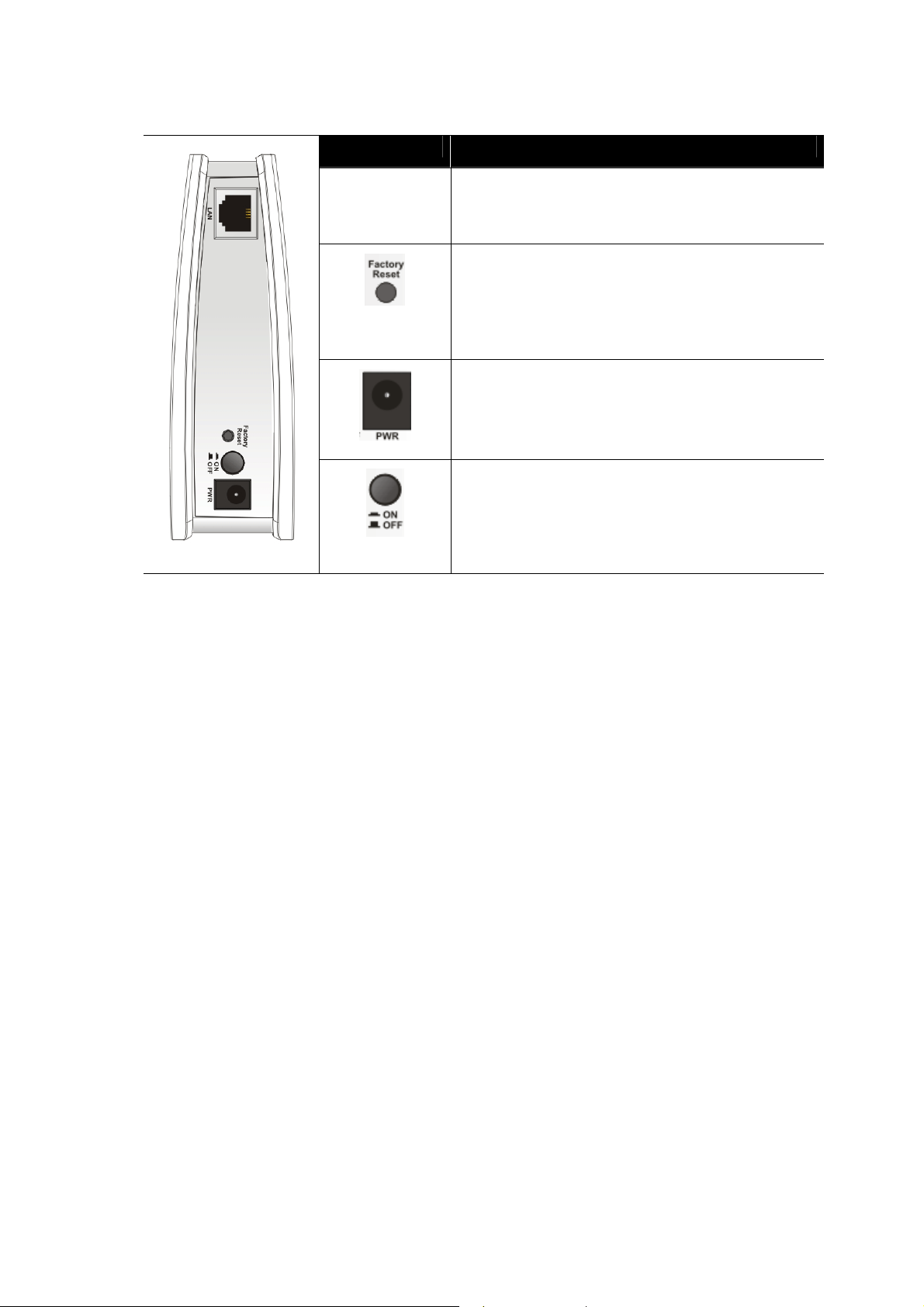
Interface Description
LAN
Connecter for xDSL / Cable modem or router.
Restore the default settings. Usage: Turn on the
router. Press the button and keep for more than 6
seconds. Then the router will restart with the
factory default configuration.
PWR: Connecter for a power adapter.
ON/OFF: Power switch.
3
VigorAP 710 User’s Guide
Page 12
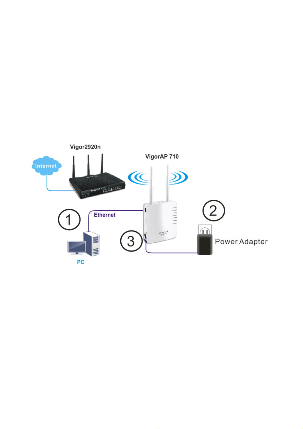
11..33 HHaarrddwwaarree IInnssttaallllaattiioonn
This section will guide you to install the VigorAP 710 through hardware connection and
configure the device’s settings through web browser.
Before starting to configure VigorAP 710, you have to connect your devices correctly.
1. Connect a computer to VigorAP710.
2. Connect the A/C power adapter to the wall socket, and then connect it to the PWR
connector of the access point.
3. Power on VigorAP 710.
4. Check all LEDs on the front panel. ACT LED should be steadily on, SSID LEDs
should be on if the access point is correctly connected to the computer.
(For the detailed information of LED status, please refer to section 1.2.)
VigorAP 710 User’s Guide
4
Page 13

Neett
N
After the network connection is built, the next step you should do is setup VigorAP 710 with
proper network parameters, so it can work properly in your network environment.
Before you can connect to the access point and start configuration procedures, your
computer must be able to get an IP address automatically (use dynamic IP address). If it’s set
to use static IP address, or you’re unsure, please follow the following instructions to
configure your computer to use dynamic IP address:
For the default IP address of this AP is set “192.168.1.2”, we recommend you to use
“192.168.1.X (except 2)” in the field of IP address on this section for your computer.
If the operating system of your computer is…
Windows 7 - please go to section 2.1
Windows 2000 - please go to section 2.2
Windows XP - please go to section 2.3
Windows Vista - please go to section 2.4
22..11 WWiinnddoowwss 77 IIPP AAddddrreessss SSeettuupp
Click Start button (it should be located at lower-left corner of your computer), then click
Control Panel. Double-click Network and Internet, and the following window will appear.
Click Network and Sharing Center.
woorrkk
w
Coonnffiigguurraattiioonn
C
Next, click Change adapter settings and click Local Area Connection.
5
VigorAP 710 User’s Guide
Page 14
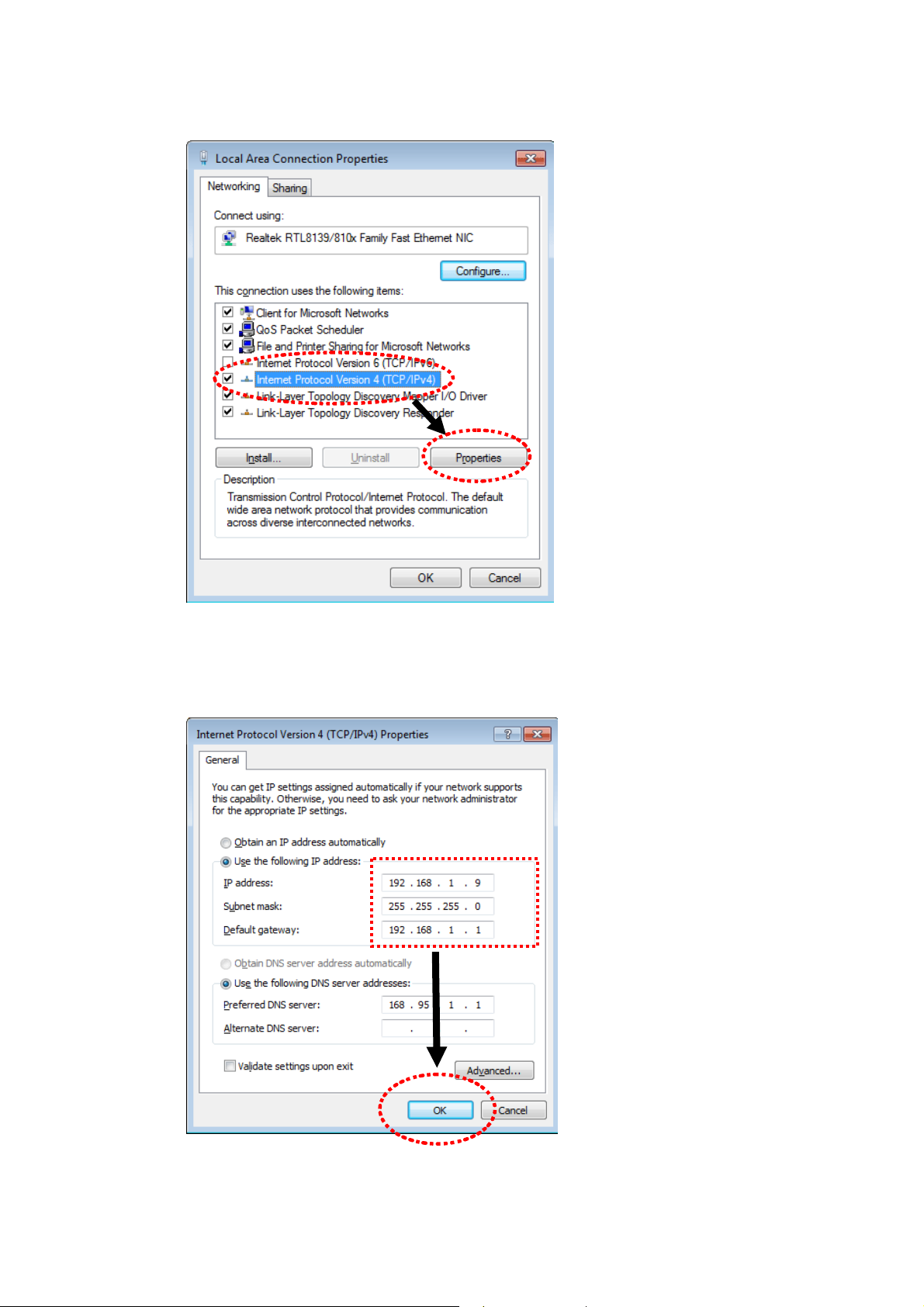
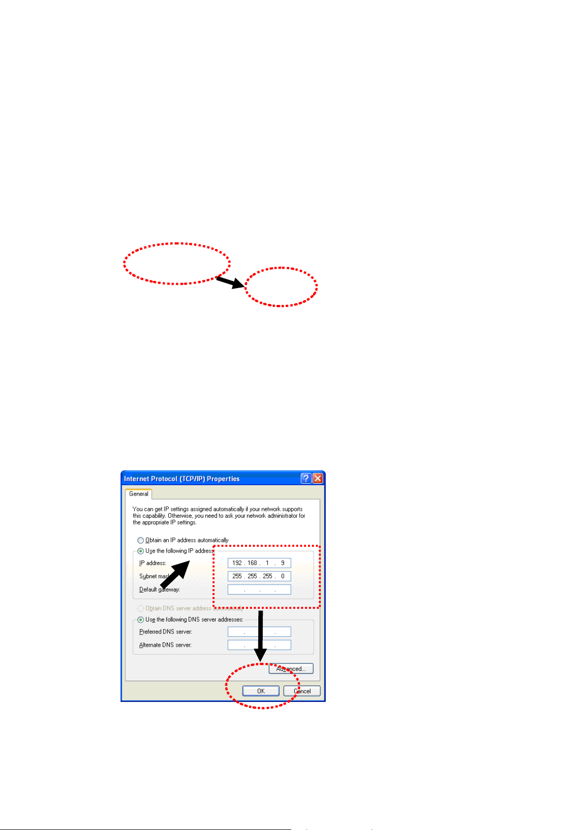
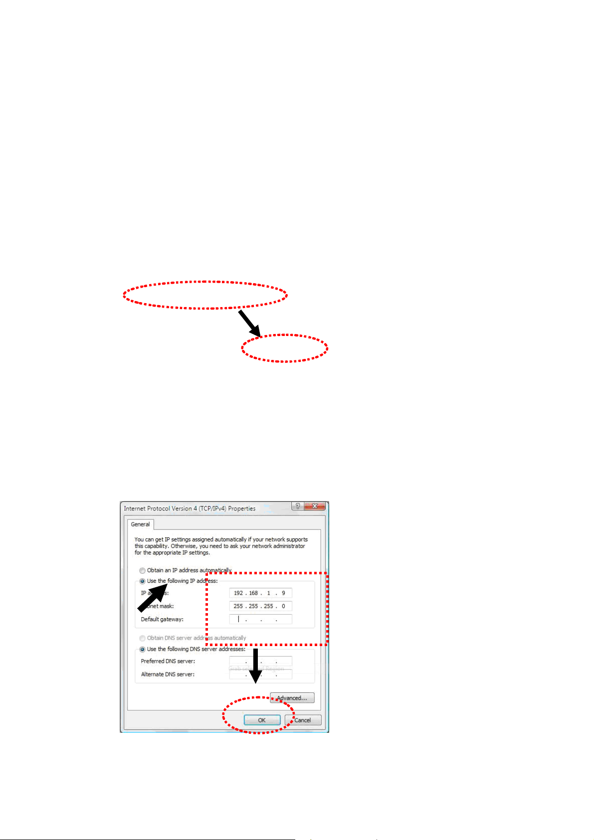
Then, select Internet Protocol Version 4 (TCP/IPv4) and click Properties.
Under the General tab, click Use the following IP address. Then input the following
settings in respective field and click OK when finish.
IP address: 192.168.1.9
Subnet Mask: 255.255.255.0
VigorAP 710 User’s Guide
6
Page 15
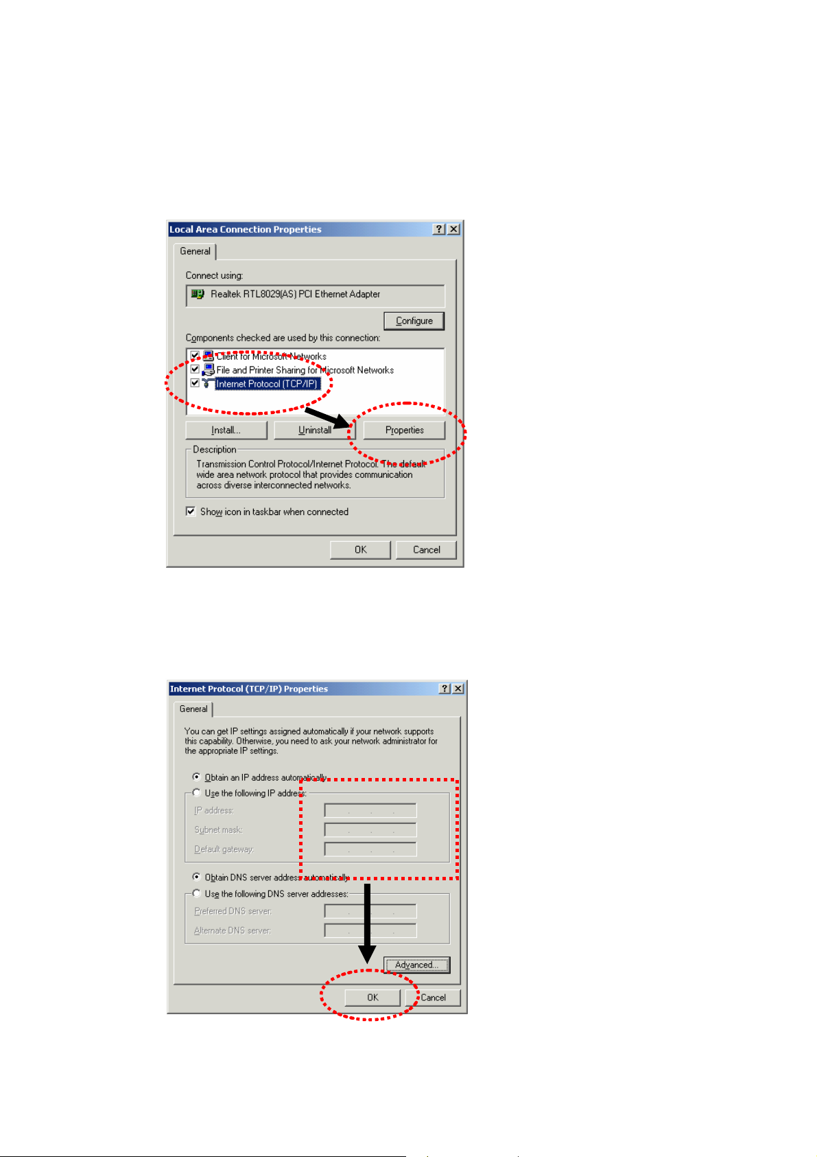
22..22 WWiinnddoowwss 22000000 IIPP AAddddrreessss SSeettuupp
Click Start button (it should be located at lower-left corner of your computer), then click
control panel. Double-click Network and Dial-up Connections icon, double click Local
Area Connection, and Local Area Connection Properties window will appear. Select
Internet Protocol (TCP/IP), then click Properties.
Select Use the following IP address, then input the following settings in respective field and
click OK when finish.
IP address: 192.168.1.9
Subnet Mask: 255.255.255.0
7
VigorAP 710 User’s Guide
Page 16
22..33 WWiinnddoowwss XXPP IIPP AAddddrreessss SSeettuupp
Click Start button (it should be located at lower-left corner of your computer), then click
control panel. Double-click Network and Internet Connections icon, click Network
Connections, and then double-click Local Area Connection, Local Area Connection
Status window will appear, and then click Properties.
Select Use the following IP address, then input the following settings in respective field and
click OK when finish:
IP address: 192.168.1.9
Subnet Mask: 255.255.255.0.
VigorAP 710 User’s Guide
8
Page 17
22..44 WWiinnddoowwss VViissttaa IIPP AAddddrreessss SSeettuupp
Click Start button (it should be located at lower-left corner of your computer), then click
control panel. Click View Network Status and Tasks, then click Manage Network
Connections. Right-click Local Area Netwrok, then select ‘Properties’. Local Area
Connection Properties window will appear, select Internet Protocol Version 4 (TCP /
IPv4), and then click Properties.
Select Use the following IP address, then input the following settings in respective field and
click OK when finish:
IP address: 192.168.1.9
Subnet Mask: 255.255.255.0.
9
VigorAP 710 User’s Guide
Page 18
22..55 AAcccceessssiinngg ttoo WWeebb UUsseerr IInntteerrffaaccee
All functions and settings of this access point must be configured via web user interface.
Please start your web browser (e.g., IE, Firefox, Google Chrome).
1. Make sure your PC connects to the VigorAP 710 correctly.
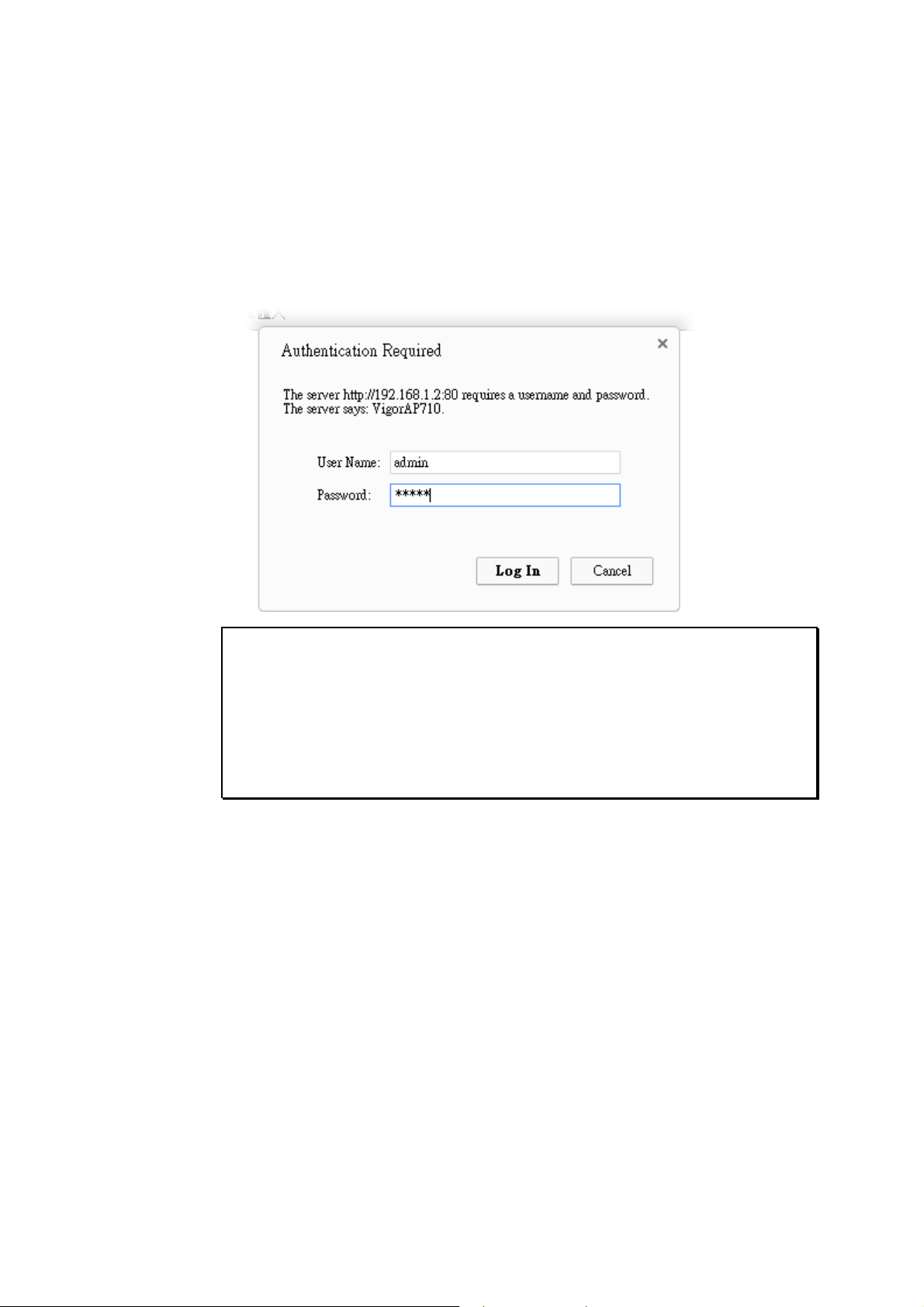
2. Open a web browser on your PC and type http://192.168.1.2. A pop-up window will
open to ask for username and password. Pease type “admin/admin” on
Username/Password and click Log In.
Note 1: You may either simply set up your computer to get IP dynamically from the
router or set up the IP address of the computer to be in the same subnet as the IP
address of VigorAP 710.
If there is no DHCP server on the network, then VigorAP 710 will have an IP
address of 192.168.1.2.
If there is DHCP available on the network, then VigorAP 710 will receive it’s
IP address via the DHCP server.
3. The Main Screen will pop up.
VigorAP 710 User’s Guide
10
Page 19
Note: If you fail to access to the web configuration, please go to “Trouble
Shooting” for detecting and solving your problem. For using the device properly, it
is necessary for you to change the password of web configuration for security and
adjust primary basic settings.
22..66 CChhaannggiinngg PPaasssswwoorrdd
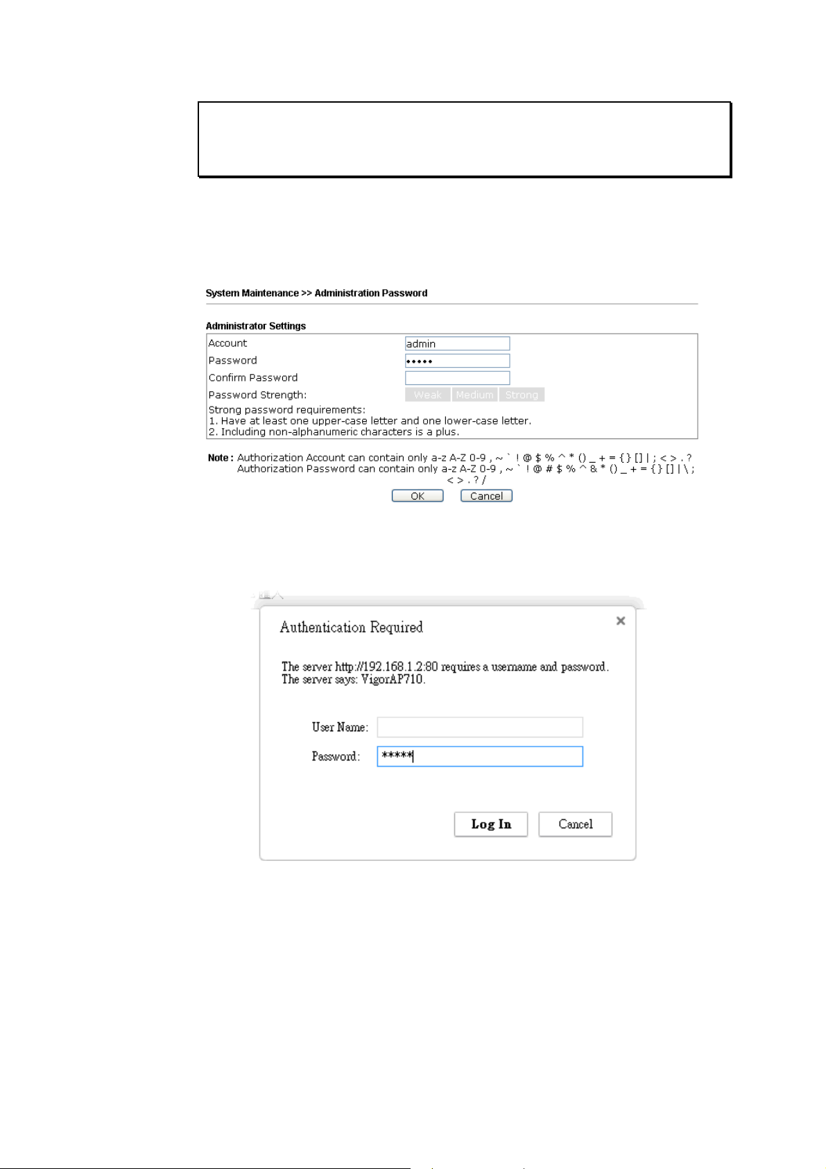
1. Please change the password for the original security of the modem.
2. Go to System Maintenance page and choose Administrator Password.
3. Enter the new login password on the field of Password. Then click OK to continue.
4. Now, the password has been changed. Next time, use the new password to access the
Web User Interface for this modem.
11
VigorAP 710 User’s Guide
Page 20
22..77 QQuuiicckk SSttaarrtt WWiizzaarrdd
Quick Start Wizard will guide you to configure 2.4G wireless setting and other
corresponding settings for Vigor Access Point step by step.
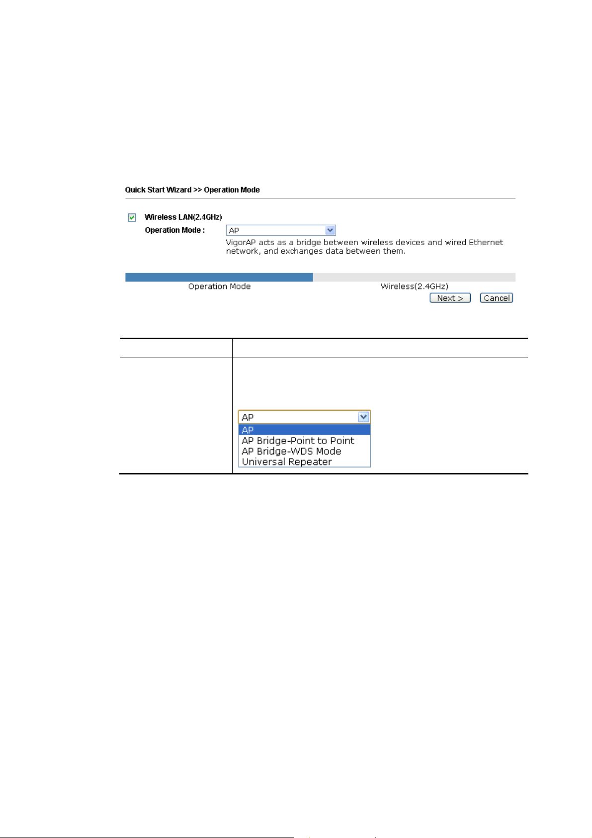
22..77..11 CCoonnffiigguurriinngg WWiirreelleessss SSeettttiinnggss –– GGeenneerraall
This page displays general settings for the operation mode selected.
Available settings are explained as follows:
Item Description
Wireless LAN
(2.4GHz)
Check the box to enable WLAN 2.4GHz for VigorAP.
Operation Mode - There are four operation modes for wireless
connection. Settings for each mode are different.
After finishing this web page configuration, please click Next to continue.
VigorAP 710 User’s Guide
12
Page 21
22..77..22 CCoonnffiigguurriinngg WWiirreelleessss SSeettttiinnggss bbaasseedd oonn tthhee OOp
In this page, the advanced settings will vary according to the operation mode chosen on
2.7.1.
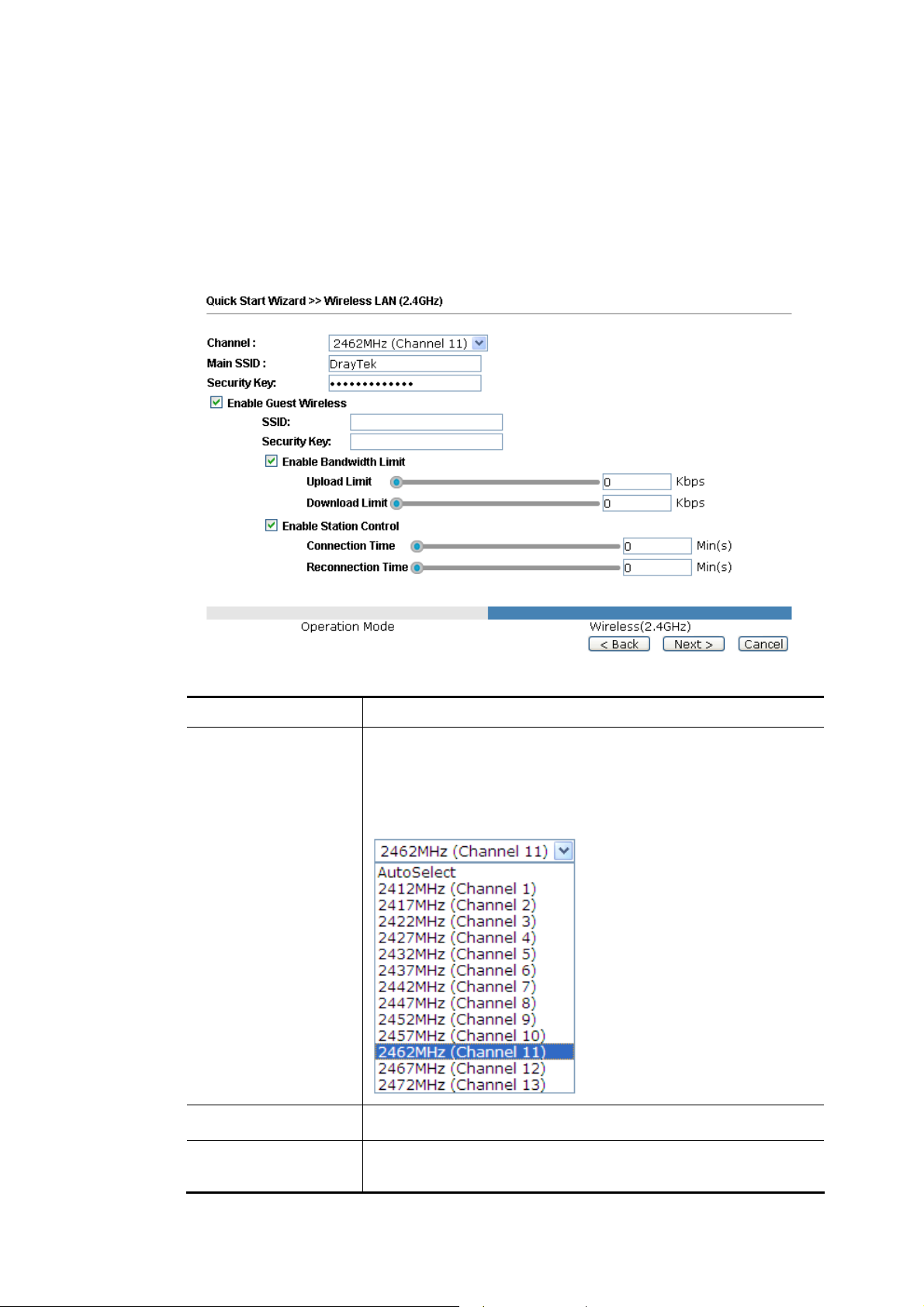
SSeettttiinnggss ffoorr AAPP
When you choose AP as the operation mode for wireless LAN (2.4GHz), you will need to
configure the following page.
peerraattiioonn MMooddee
Available settings are explained as follows:
Item Description
Channel
Means the channel frequency of the wireless LAN. The default
channel is 6. You may switch channel if the selected channel is
under serious interference. If you have no idea of choosing the
frequency, please select AutoSelect to let system determine for
you.
Main SSID
Security Key
Set a name for VigorAP 710 to be identified.
Type 8~63 ASCII characters, such as 012345678..(or 64
Hexadecimal digits leading by 0x, such as "0x321253abcde...").
13
VigorAP 710 User’s Guide
Page 22
Enable Guest
Wireless
Check the box to enable the guest wireless setting.
Such feature is especially useful for free Wi-Fi service. For
example, a coffee shop offers free Wi-Fi service for its guests
for one hour every day.
SSID – Set a name for VigorAP which can be identified and
connected by wireless guest.
Security Key– Set 8~63 ASCII characters or 8~63 ASCII
characters which can be used for logging into VigorAP 710 by
wireless guest.
Enable Bandwidth Limit – Check the box to define the
maximum speed of the data uploading/downloading which will
be used for the guest connecting to Vigor device with the same
SSID.
Upload Limit – Scroll the radio button to choose the
value you want.
Download Limit –Scroll the radio button to choose
the value you want.
Enable Station Control – Check the box to set the duration for
the guest connecting /reconnecting to Vigor device.
Connection Time –Scroll the radio button to choose
the value you want.
Reconnection Time –Scroll the radio button to
choose the value you want.
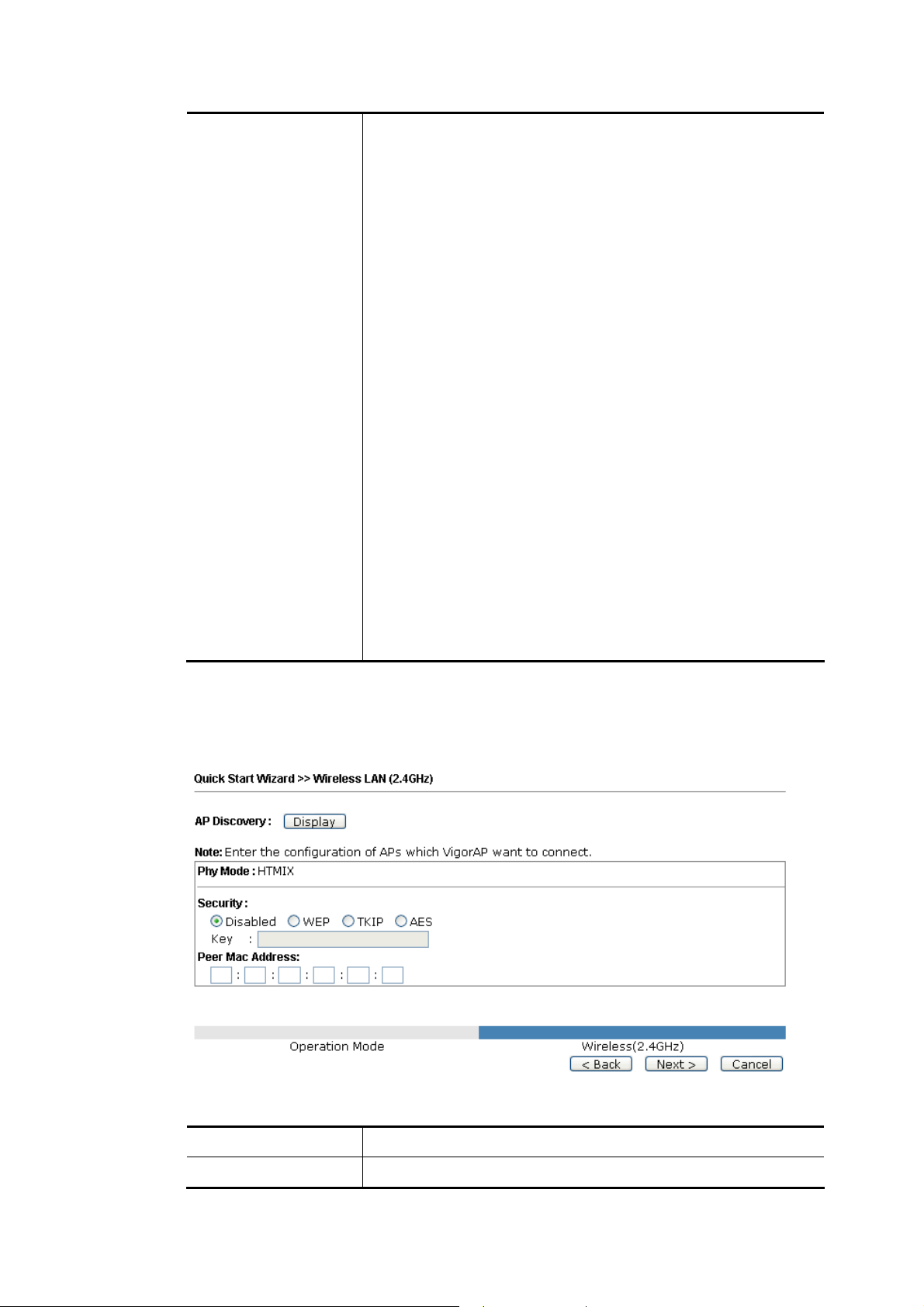
SSeettttiinnggss ffoorr AAPP BBrriiddggee--PPooiinntt ttoo PPooiinntt
When you choose AP Bridge-Point to Point, after clicking Next, you will need to configure
the following page.
Available settings are explained as follows:
Item Description
AP Discovery
VigorAP 710 User’s Guide
Click this button to open the AP Discovery dialog. VigorAP 710
14
Page 23

can scan all regulatory channels and find working APs in the
neighborhood.
Phy Mode
Security
Peer MAC Address
Data will be transmitted via HTMIX communication channel .
Each access point should be setup to the same Phy mode for
connecting with each other.
Select WEP, TKIP or AES as the encryption algorithm. Type the
key number if required.
Type the peer MAC address for the access point that VigorAP
710 connects to.
15
VigorAP 710 User’s Guide
Page 24
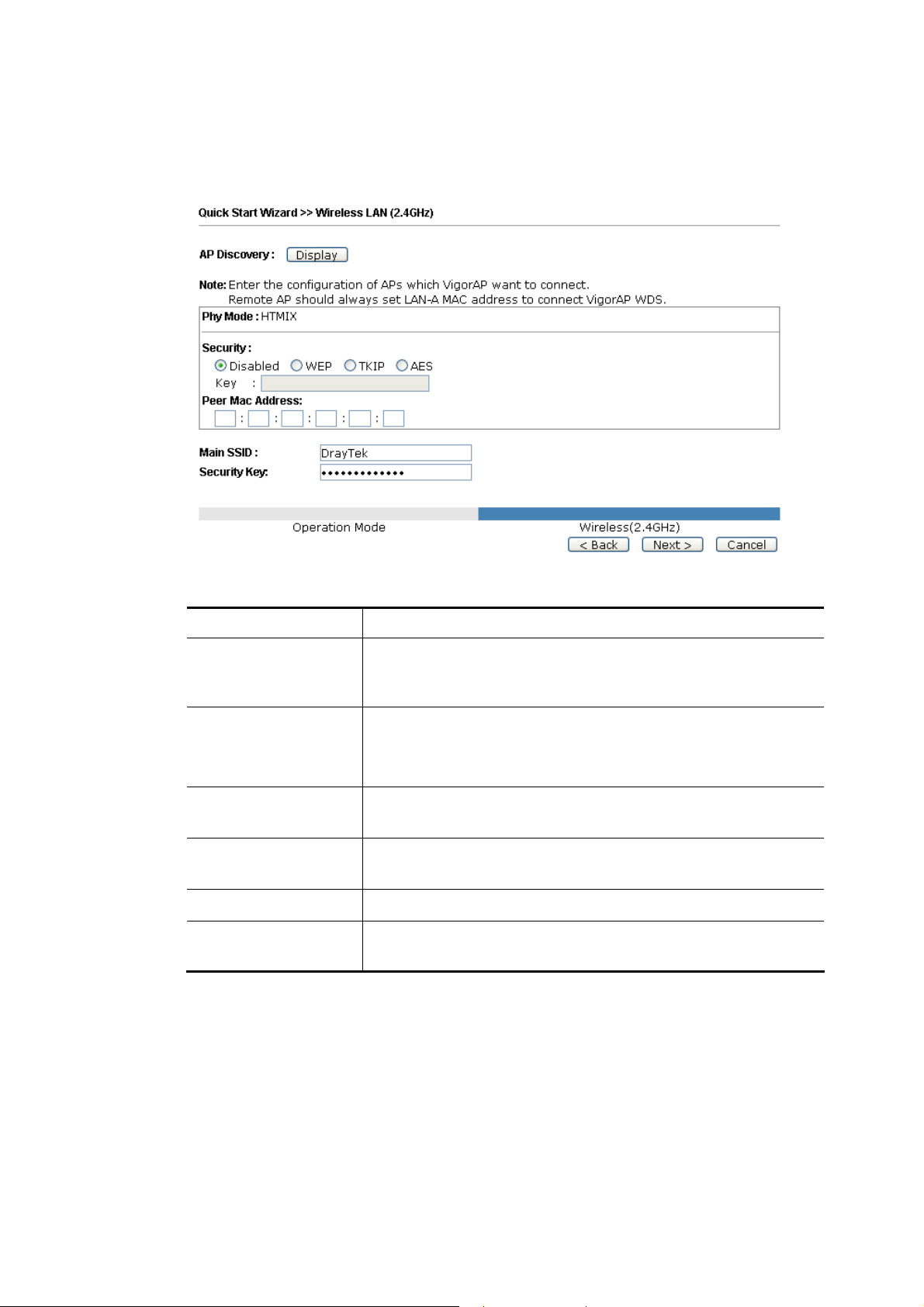
SSeettttiinnggss ffoorr AAPP BBrriiddggee--WWDDSS
When you choose AP Bridge-WDS, after clicking Next, you will need to configure the
following page.
Available settings are explained as follows:
Item Description
AP Discovery
Click this button to open the AP Discovery dialog. VigorAP 710
can scan all regulatory channels and find working APs in the
neighborhood.
Phy Mode
Data will be transmitted via HTMIX communication channel .
Each access point should be setup to the same Phy mode for
connecting with each other.
Security
Select WEP, TKIP or AES as the encryption algorithm. Type the
key number if required.
Peer MAC Address
Type the peer MAC address for the access point that VigorAP
710 connects to.
Main SSID
Security Key
Set a name for VigorAP 710 to be identified.
Type 8~63 ASCII characters, such as 012345678..(or 64
Hexadecimal digits leading by 0x, such as "0x321253abcde...").
VigorAP 710 User’s Guide
16
Page 25
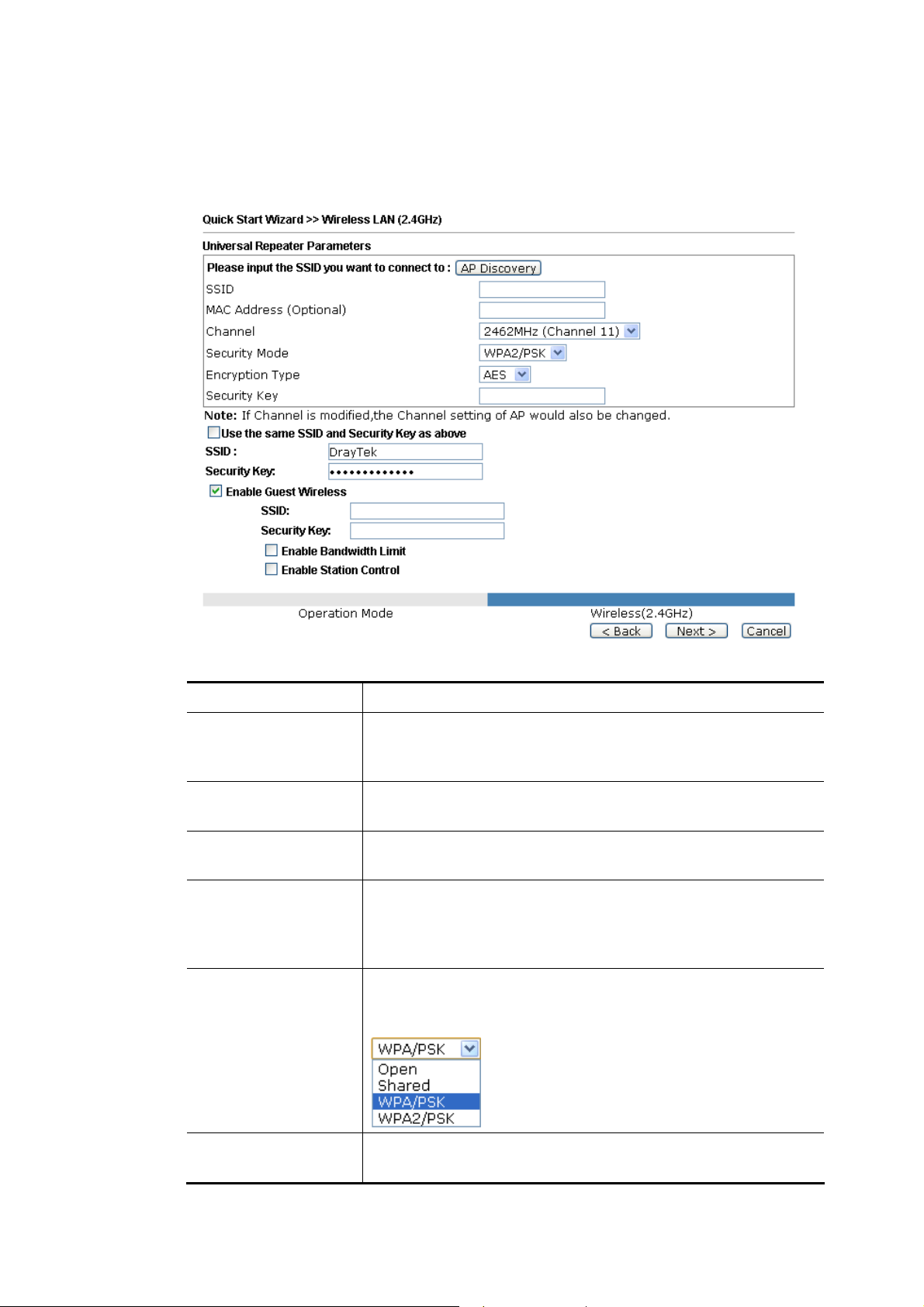
SSeettttiinnggss ffoorr UUnniivveerrssaall RReeppeeaatteerr
When you choose AP Bridge-Universal Repeater, after clicking Next, you will need to
configure the following page.
Available settings are explained as follows:
Item Description
AP Discovery
Click this button to open the AP Discovery dialog. VigorAP 710
can scan all regulatory channels and find working APs in the
neighborhood.
SSID
Means the identification of the wireless LAN. SSID can be any
text numbers or various special characters.
MAC Address
Type the MAC address for the access point.
(Optional)
Channel
Choose the channel of frequency of the wireless LAN. You may
switch channel if the selected channel is under serious
interference. If you have no idea of choosing the frequency,
simply use the default setting.
Security Mode
There are several modes provided for you to choose. Each mode
will bring up different parameters (e.g., WEP keys, Pass Phrase)
for you to configure.
Encryption Type for
Open/Shared
This option is available when Open/Shared is selected as
Security Mode.
17
VigorAP 710 User’s Guide
Page 26
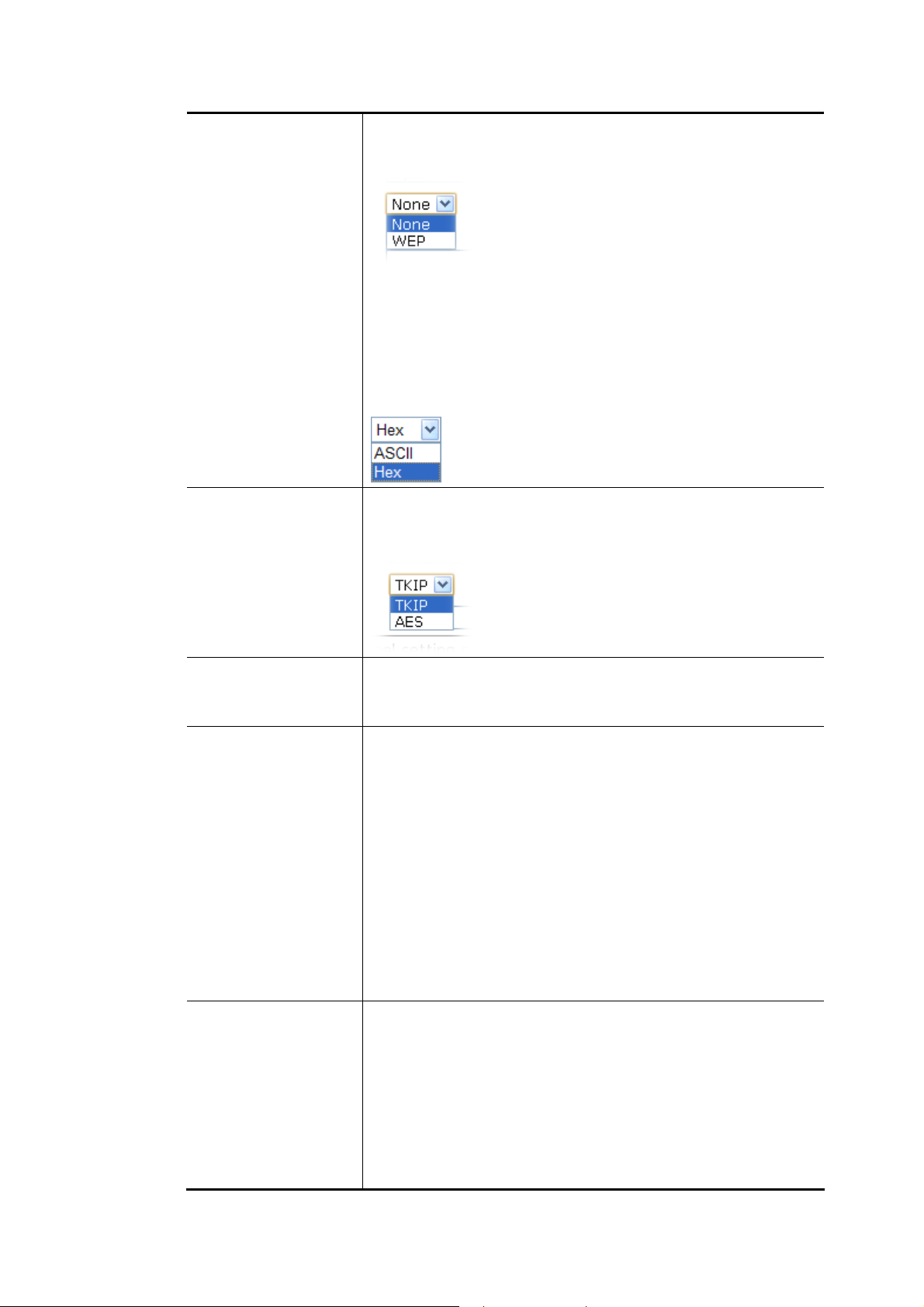
Choose None to disable the WEP Encryption. Data sent to the
AP will not be encrypted. To enable WEP encryption for data
transmission, please choose WEP.
WEP Keys - Four keys can be entered here, but only one key
can be selected at a time. The format of WEP Key is restricted to
5 ASCII characters or 10 hexadecimal values in 64-bit
encryption level, or restricted to 13 ASCII characters or 26
hexadecimal values in 128-bit encryption level. The allowed
content is the ASCII characters from 33(!) to 126(~) except '#'
and ','.
Encryption Type for
WPA/PSK and
WPA2/PSK
This option is available when WPA/PSK or WPA2/PSK is
selected as Security Mode.
Select TKIP or AES as the algorithm for WPA.
Security Key
Use the same SSID
and Security Key as
above
Enable Guest
Wireless
Type 8~63 ASCII characters, such as 012345678..(or 64
Hexadecimal digits leading by 0x, such as "0x321253abcde...").
Such feature is available for WPA/PSK or WPA2/PSK mode.
In general, under the network environment, same SSID and
security key can be used for the host (wireless client) and the
repeater (VigorAP 710) in Universal Repeater mode. Check it to
use the same SSID and security key configured as above.
SSID - SSID can be any text numbers or various special
characters. For VigorAP 710 is set as “Repeater”, the purpose of
the device is to extend the Wi-Fi service. Therefore, the
characters set here will be regarded as “main SSID”. Other
wireless client can receive the wireless signal from VigorAP 710
by using the SSID configured here.
Security - Set 8~63 ASCII characters or 64 Hexadecimal digits
which can be used for logging into VigorAP 710 by other
wireless client.
Check the box to enable the guest wireless setting.
Such feature is especially useful for free Wi-Fi service. For
example, a coffee shop offers free Wi-Fi service for its guests
for one hour every day.
VigorAP 710 User’s Guide
SSID – Set a name for VigorAP which can be identified and
connected by wireless guest.
Security Key– Set 8~63 ASCII characters or 8~63 ASCII
characters which can be used for logging into VigorAP 710 by
18
Page 27

wireless guest.
Enable Bandwidth Limit – Check the box to define the
maximum speed of the data uploading/downloading which will
be used for the guest connecting to Vigor device with the same
SSID.
Upload Limit – Scroll the radio button to choose the
value you want.
Download Limit –Scroll the radio button to choose
the value you want.
Enable Station Control – Check the box to set the duration for
the guest connecting /reconnecting to Vigor device.
Connection Time –Scroll the radio button to choose
the value you want.
Reconnection Time –Scroll the radio button to
choose the value you want.
After finishing this web page configuration, please click Next to continue.
19
VigorAP 710 User’s Guide
Page 28
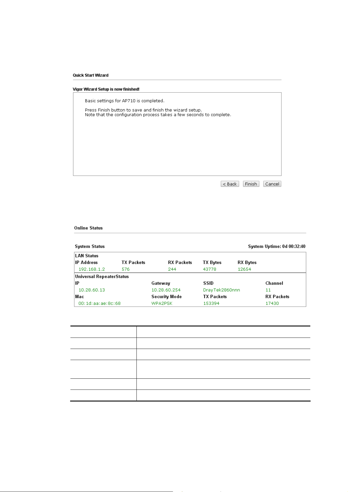
22..77..33 FFiinniisshhiinngg tthhee WWiirreelleessss SSeettttiinnggss WWiizzaarrdd
When you see this page, it means the wireless setting wizard is almost finished. Just click
Finish to save the settings and complete the setting procedure.
22..88 OOnnlliinnee SSttaattuuss
The online status shows the LAN status, Station Link Status for such device.
Detailed explanation is shown below:
Item Description
IP Address
TX Packets
RX Packets
TX Bytes
RX Bytes
VigorAP 710 User’s Guide
Displays the IP address of the LAN interface.
Displays the total transmitted packets at the LAN interface.
Displays the total number of received packets at the LAN
interface.
Displays the total transmitted size at the LAN interface.
Displays the total number of received size at the LAN interface.
20
Page 29
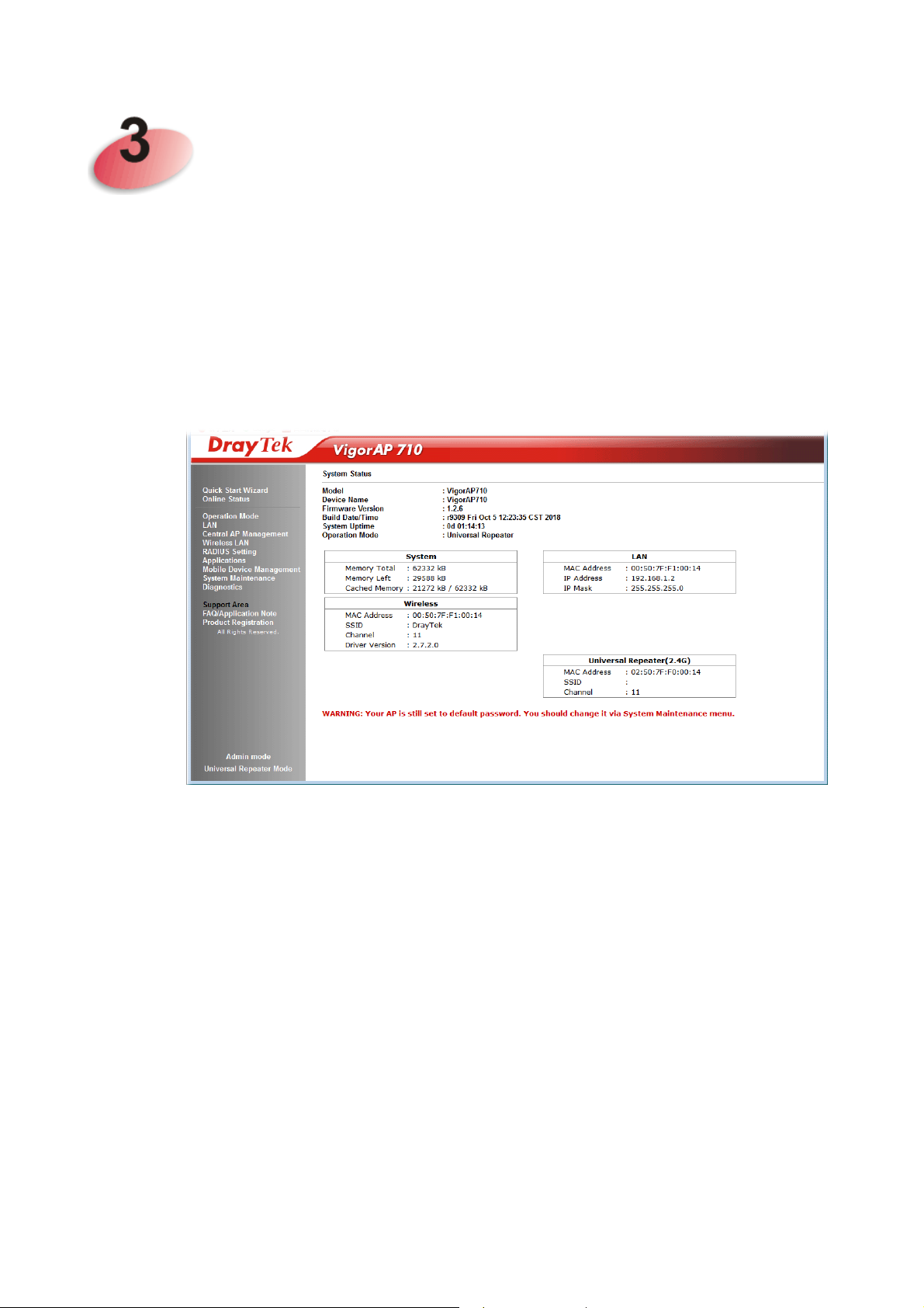
Addvvaanncceedd
A
This chapter will guide users to execute advanced (full) configuration. As for other examples
of application, please refer to chapter 5.
1. Open a web browser on your PC and type http://192.168.1.2. The window will ask for
typing username and password.
2. Please type “admin/admin” on Username/Password for administration operation.
Now, the Main Screen will appear. Be aware that “Admin mode” will be displayed on the
bottom left side.
Coonnffiigguurraattiioonn
C
21
VigorAP 710 User’s Guide
Page 30
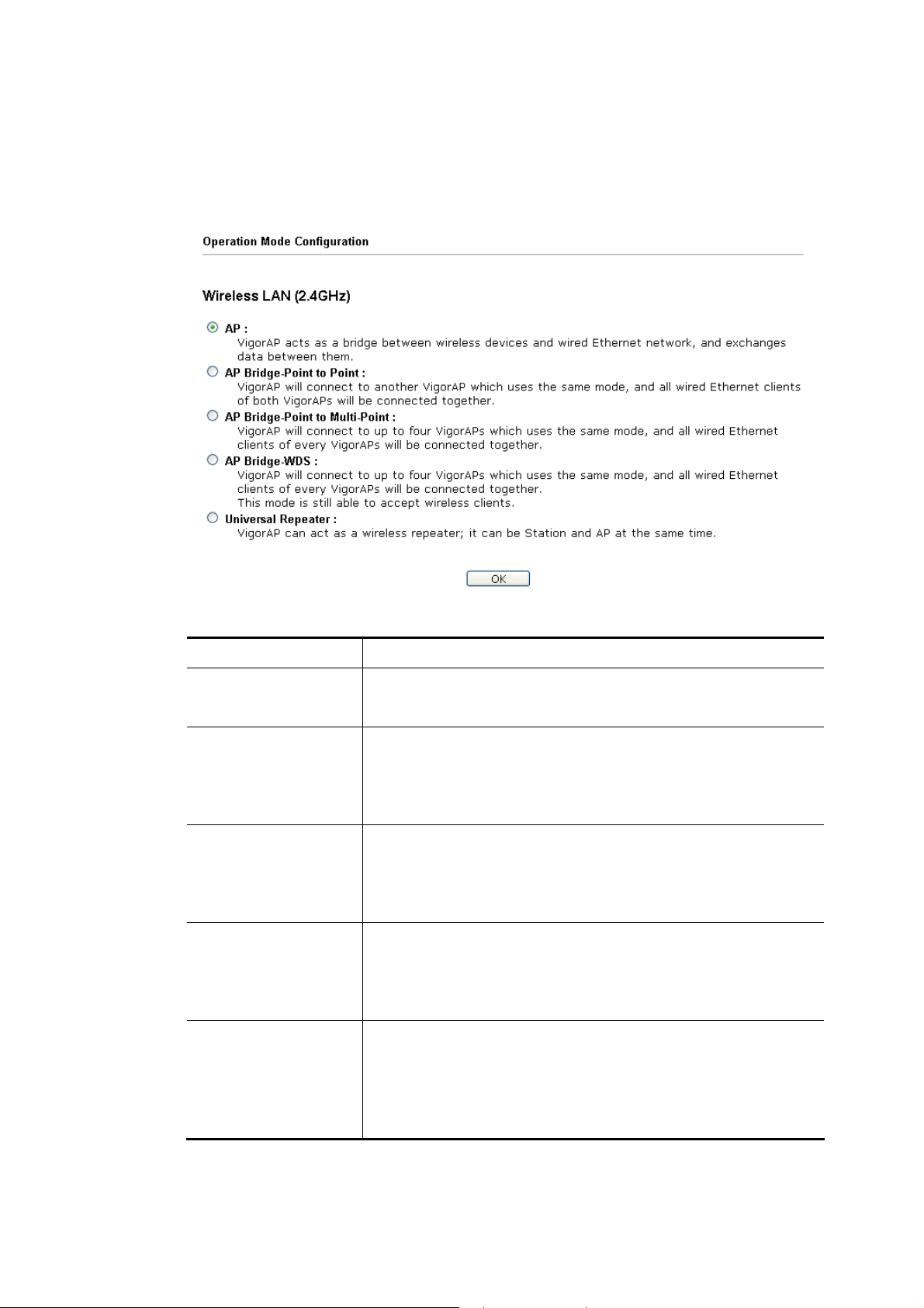
33..11 OOppeerraattiioonn MMooddee
This page provides several available modes for you to choose for different conditions. Click
any one of them and click OK. The system will configure the required settings
automatically.
Available settings are explained as follows:
Item Description
AP
AP Bridge-Point to
Point
AP Bridge-Point to
Multi-Point
AP Bridge-WDS
Universal Repeater
This mode allows wireless clients to connect to access point and
exchange data with the devices connected to the wired network.
This mode can establish wireless connection with another
VigorAP 710 using the same mode, and link the wired network
which these two VigorAP 710s connected together. Only one
access point can be connected in this mode.
This mode can establish wireless connection with other VigorAP
710s using the same mode, and link the wired network which
these VigorAP 710s connected together. Up to 4 access points
can be connected in this mode.
This mode is similar to AP Bridge to Multi-Point, but access
point is not work in bridge-dedicated mode, and will be able to
accept wireless clients while the access point is working as a
wireless bridge.
This product can act as a wireless range extender that will help
you to extend the networking wirelessly. The access point can
act as Station and AP at the same time. It can use Station
function to connect to a Root AP and use AP function to service
all wireless clients within its coverage.
VigorAP 710 User’s Guide
22
Page 31

Note: The Wireless LAN settings will be changed according to the Operation Mode
selected here. For the detailed information, please refer to the section of Wireless LAN.
33..22 LLAANN
Local Area Network (LAN) is a group of subnets regulated and ruled by modem.
33..22..11 GGeenneerraall SSeettuupp
Click LAN to open the LAN settings page and choose General Setup.
Note: Such page will be changed according to the Operation Mode selected. The
following screen is obtained by choosing AP as the operation mode.
Available settings are explained as follows:
Item Description
LAN IP Network
Configuration
Enable DHCP Client – When it is enabled, VigorAP 710 will
be treated as a client and can be managed / controlled by AP
Management server offered by Vigor router (e.g., Vigor2860).
IP Addr ess – Type in private IP address for connecting to a
local private network (Default: 192.168.1.2).
Subnet Mask – Type in an address code that determines
the size of the network. (Default: 255.255.255.0/ 24)
Default Gateway - In general, it is not really necessary to
specify a gateway for VigorAP 710. However, if it is
required, simply type an IP address as the gateway for
VigorAP 710. It will be convenient for the access point
acquiring more service (e.g., accessing NTP server) from
Vigor router.
Enable Management VLAN – VigorAP 710 supports tag-based
VLAN for wireless clients accessing Vigor device. Only the
clients with the specified VLAN ID can access into VigorAP
23
VigorAP 710 User’s Guide
Page 32

710.
VLAN ID – Type the number as VLAN ID tagged on the
transmitted packet. “0” means no VALN tag.
DHCP Server
Configuration
DHCP stands for Dynamic Host Configuration Protocol. DHCP
server can automatically dispatch related IP settings to any local
user configured as a DHCP client.
Enable Server - Enable Server lets the modem assign IP address
to every host in the LAN.
Start IP Address - Enter a value of the IP address pool for
the DHCP server to start with when issuing IP addresses. If
the 1st IP address of your modem is 192.168.1.2, the
starting IP address must be 192.168.1.3 or greater, but
smaller than 192.168.1.254.
End IP Address - Enter a value of the IP address pool for
the DHCP server to end with when issuing IP addresses.
Subnet Mask - Type in an address code that determines
the size of the network. (Default: 255.255.255.0/ 24)
Default Gateway - Enter a value of the gateway IP address
for the DHCP server.
Lease Time - It allows you to set the leased time for the
specified PC.
Primary DNS Server - You must specify a DNS server IP
address here because your ISP should provide you with
usually more than one DNS Server. If your ISP does not
provide it, the modem will automatically apply default
DNS Server IP address: 194.109.6.66 to this field.
Secondary DNS Server - You can specify secondary DNS
server IP address here because your ISP often provides you
more than one DNS Server. If your ISP does not provide it,
the modem will automatically apply default secondary
DNS Server IP address: 194.98.0.1 to this field.
Relay Agent - Specify which subnet that DHCP server is located
the relay agent should redirect the DHCP request to.
DHCP Server IP Address for Relay Agent - It is available
when Enable Relay Agent is selected. Set the IP address of
the DHCP server you are going to use so the Relay Agent
can help to forward the DHCP request to the DHCP server.
Primary DNS Server - You must specify a DNS server IP
address here because your ISP should provide you with
usually more than one DNS Server. If your ISP does not
provide it, the modem will automatically apply default
DNS Server IP address: 194.109.6.66 to this field.
Secondary DNS Server - You can specify secondary DNS
server IP address here because your ISP often provides you
more than one DNS Server. If your ISP does not provide it,
the modem will automatically apply default secondary
DNS Server IP address: 194.98.0.1 to this field.
VigorAP 710 User’s Guide
24
Page 33

Disable Server - Disable Server lets you manually or use other
DHCP server to assign IP address to every host in the LAN.
Primary DNS Server - You must specify a DNS server IP
address here because your ISP should provide you with
usually more than one DNS Server. If your ISP does not
provide it, the modem will automatically apply default
DNS Server IP address: 194.109.6.66 to this field.
Secondary DNS Server - You can specify secondary DNS
server IP address here because your ISP often provides you
more than one DNS Server. If your ISP does not provide it,
the modem will automatically apply default secondary
DNS Server IP address: 194.98.0.1 to this field.
Trust DHCP Server IP for WLAN –There is no right for
such VigorAP to assign IP address for wireless LAN user.
However, you can specify another valid DHCP server on
other VigorAP to make the wireless LAN client obtaining
the IP address from the designated DHCP server.
Specify a DHCP server in such field. All the IP addresses
of the devices on LAN of VigorAP will be assigned via
such specified server. It is used to avoid IP assignment
interference due to multiple DHCP servers in one LAN.
After finishing this web page configuration, please click OK to save the settings.
25
VigorAP 710 User’s Guide
Page 34

33..22..22 WWeebb PPoorrttaall
This page allows you to configure a profile with specified URL for accessing into or display
a message when a wireless/LAN user connects to Internet through this router. No matter
what the purpose of the wireless/LAN client is, he/she will be forced into the URL
configured here while trying to access into the Internet or the desired web page through this
router. That is, a company which wants to have an advertisement for its products to users can
specify the URL in this page to reach its goal.
Each item is explained as follows:
Item Description
Index
Display the number link which allows you to configure the
profile.
Enable
Comments
Check the box to enable such profile.
Display the content (Disable, URL Redirect or Message) of the
profile.
Login Mode
Interface
Preview
Display the login mode that a client uses to access into Internet.
Display the applied interfaces of the profile.
Open a preview window according to the configured settings.
After finishing this web page configuration, please click OK to save the settings.
VigorAP 710 User’s Guide
26
Page 35

To configure the profile, click any index number link to open the following page.
Available settings are explained as follows:
Item Description
Enable
Comments
Welcome message
Check the box to enable this function.
Enter a brief comment to explain such web portal profile.
Enter words or sentences here. The message will be displayed on
the screen for several seconds when the wireless users access
into the web page through the router.
Default – Click it to restore the default content.
Redirect Page
None - User can access into Internet directly.
URL Redirect - Any user who wants to access into Internet
through this router will be redirected to the URL specified here
first. It is a useful method for the purpose of advertisement. For
example, force the wireless user(s) in hotel to access into the
web page that the hotel wants the user(s) to visit.
Authentication
None – User can access into Internet directly without
authentication.
Button Click – When a client tries to access into Internet, a
welcome message page with a button named “Accept” will
appear on the screen first. The client must click that button
(Accept) and then he/she is allowed to access Internet.
Applied Interfaces
Check the box(es) representing different interfaces to be applied
by such profile.
LAN – If it is selected and Universal Repeater is specified
as connection mode for such AP, both LAN client and
WLAN client can access into Internet via web portal. Yet,
if AP mode is selected, only wireless LAN client shall
27
VigorAP 710 User’s Guide
Page 36

access into Internet via web portal.
WLAN - The advantage is that each SSID (1/2/3/4) for
wireless network can be applied with different web portal
separately.
After finishing all the settings here, please click OK to save the configuration.
VigorAP 710 User’s Guide
28
Page 37

33..33 CCeennttrraall AAPP MMaannaaggeemmeenntt
Such menu allows you to configure VigorAP device to be managed by Vigor router.
33..33..11 GGeenneerraall SSeettuupp
Available settings are explained as follows:
Item Description
Enable AP
Management
Enable Auto
Provision
33..33..22 AAPPMM LLoogg
This page will display log information related to wireless stations connected to VigorAP 710
and central AP management.
Such information also will be delivered to Vigor router (e.g., Vigor2860 or Vigor2925 series)
and be shown on Central AP Management>>Event Log of Vigor router.
Check the box to enable the function of AP Management
(APM).
VigorAP 710 can be controlled under Central AP Management
in Vigor2860 series. When both Vigor2860 series and VigorAP
710 have such feature enabled, once VigorAP 710 is registered
to Vigor2860 series, the WLAN profile pre-configured on
Vigor2860 series will be applied to VigorAP 710 immediately.
Thus, it is not necessary to configure VigorAP 710 separately.
29
VigorAP 710 User’s Guide
Page 38

33..33..33 FFuunnccttiioonn SSuuppppoorrtt LLiisstt
Click the Client tab to list the AP management functions that the Access Points support
under different firmware versions.
Note: DrayTek central wireless management (AP Management) lets control, efficiency,
monitoring and security of your company-wide wireless access easier to be managed.
Inside the web user interface, we call “central wireless management” as Central AP
Management which supports mobility, client monitoring/reporting and load-balancing to
multiple APs. For central wireless management, you will need a Vigor2862 or Vigor2926
series router; there is no per-node licensing or subscription required. With the unified user
interface of Vigor2862 Combo WAN series and Vigor2926 Triple WAN series, the
multiple deployment of VigorAP 710 can be clear at the first sight. For multiple wireless
clients, to apply the AP Load Balancing to the multiple APs will manage wireless traffic
with smooth flow and enhanced efficiency.
VigorAP 710 User’s Guide
30
Page 39

33..33..44 OOvveerrllooaadd MMaannaaggeemmeenntt
Load Balance can help to distribute the traffic for all of the access points (e.g., VigorAP 710)
registered to Vigor router. Thus, the bandwidth will not be occupied by certain access points.
However, traffic overload might be occurred if too many wireless stations connected to
VigorAP 710 for data incoming and outgoing. Therefore, “Force Overload Disassociation” is
required to terminate the network connection of the client’s station to release network traffic.
When the function of “Force Overload Disassociation” in web user interface of Vigor router
(e.g., Vigor2862 or Vigor2926 series) is enabled, wireless clients specified in black list of
such web page will be disassociated to solve the problem of traffic overload.
The following web page is used to configure white list and black list for wireless stations.
Available settings are explained as follows:
Item Description
White List/Black List
Display the information (such as index number, MAC address
and comment) for all of the members in White List/Black List.
Wireless stations listed in Black List will be forcefully
disconnected first when traffic overload occurs and “Force
Overload Disassociation” is enabled.
Client’s MAC
Specify the MAC Address of the remote/local client.
Address
Apply to
White List – MAC address listed inside Client’s MAC Address
will be categorized as one of members in White List.
Black List - MAC address listed inside Client’s MAC Address
will be categorized as one of members in Black List.
Add
Delete
Edit
Add a new MAC address into the White List/Black List.
Delete the selected MAC address in the White List/Black List.
Edit the selected MAC address in the White List/Black List.
31
VigorAP 710 User’s Guide
Page 40

Cancel
33..33..55 SSttaattuuss ooff SSeettttiinnggss
Load Balance can help to distribute the traffic for all of the access points (e.g., VigorAP710s)
registered to Vigor 2862 or Vigor2926 series. This web page displays the settings related to
Load Balance for VigorAP 710. In which, By Station Number, By Traffic and Force
Overload Disassociation indicate settings configured in Vigor 2862 or Vigor2926 series.
“X” means the function is not enabled or VigorAP 710 has not registered to any Vigor router
yet.
Give up the configuration.
Below shows a setting example for Load Balance settings configured in Vigor 2862 or
Vigor2926 series.
VigorAP 710 User’s Guide
32
Page 41

33..44 GGeenneerraall CCoonncceeppttss ffoorr WWiirreelleessss LLAANN
The VigorAP 710 is equipped with a wireless LAN interface compliant with the standard
IEEE 802.11n draft 2 protocol. To boost its performance further, the VigorAP 710 is also
loaded with advanced wireless technology to lift up data rate up to 300 Mbps*. Hence, you
can finally smoothly enjoy stream music and video.
Note:
* The actual data throughput will vary according to the network conditions and
environmental factors, including volume of network traffic, network overhead and
building materials.
In an Infrastructure Mode of wireless network, VigorAP 710 plays a role as an Access Point
(AP) connecting to lots of wireless clients or Stations (STA). All the STAs will share the
same Internet connection via VigorAP 710. The General Setup will set up the information
of this wireless network, including its SSID as identification, located channel etc.
SSeeccuurriittyy OOvveerrvviieeww
WEP (Wired Equivalent Privacy) is a legacy method to encrypt each frame transmitted via
radio using either a 64-bit or 128-bit key. Usually access point will preset a set of four keys
and it will communicate with each station using only one out of the four keys.
WPA (Wi-Fi Protected Access), the most dominating security mechanism in industry, is
separated into two categories: WPA-personal or called WPA Pre-Share Key (WPA/PSK),
and WPA-Enterprise or called WPA/802.1x.
In WPA-Personal, a pre-defined key is used for encryption during data transmission. WPA
applies Temporal Key Integrity Protocol (TKIP) for data encryption while WPA2 applies
AES. The WPA-Enterprise combines not only encryption but also authentication.
Since WEP has been proved vulnerable, you may consider using WPA for the most secure
connection. You should select the appropriate security mechanism according to your needs.
No matter which security suite you select, they all will enhance the over-the-air data
protection and /or privacy on your wireless network. The VigorAP 710 is very flexible and
can support multiple secure connections with both WEP and WPA at the same time.
WWPPSS IInnttrroodduuccttiioonn
WPS (Wi-Fi Protected Setup) provides easy procedure to make network connection
between wireless station and wireless access point (VigorAP 710) with the encryption of
WPA and WPA2.
It is the simplest way to build connection between wireless network clients and VigorAP 710.
Users do not need to select any encryption mode and type any long encryption passphrase to
setup a wireless client every time. He/she only needs to press a button on wireless client, and
WPS will connect for client and VigorAP 710 automatically.
33
VigorAP 710 User’s Guide
Page 42

Note: Such function is available for the wireless station with WPS supported.
There are two methods to do network connection through WPS between AP and Stations:
pressing the Start PBC button or using PIN Code.
On the side of VigorAP 710 series which served as an AP, press WPS button once on the
front panel of VigorAP 710 or click Start PBC on web configuration interface. On the side
of a station with network card installed, press Start PBC button of network card.
If you want to use PIN code, you have to know the PIN code specified in wireless client.
Then provide the PIN code of the wireless client you wish to connect to the VigorAP 710.
VigorAP 710 User’s Guide
34
Page 43

33..55 WWiirreelleessss LLAANN SSeettttiinnggss ffoorr AAPP MMooddee
When you choose AP as the operation mode, the Wireless LAN menu items will include
General Setup, Security, Access Control, WPS, Advanced Setting, AP Discovery, WMM
Configuration, Bandwidth Management, Airtime Fairness, Station Control, Roaming, and
Station List.
Note: The Wireless LAN settings will be changed according to the Operation Mode
selected in section 3.1.
33..55..11 GGeenneerraall SSeettuupp
By clicking the General Setup, a new web page will appear so that you could configure the SSID and the wireless channel. Please refer to the following figure for more information.
Available settings are explained as follows:
Item Description
Enable Wireless LAN
Check the box to enable wireless function.
35
VigorAP 710 User’s Guide
Page 44

Enable Client Limit
Enable Client Limit
per SSID
Mode
Channel
Check the box to set the maximum number of wireless stations
which try to connect Internet through Vigor AP. The number
you can set is from 3 to 64.
Define the maximum number of wireless stations per SSID
which try to connect to Internet through Vigor device. The
number you can set is from 3 to 64.
At present, VigorAP 710 can connect to 11b only, 11g only,
11n only, Mixed (11b+11g), Mixed (11g+11n) and Mixed
(11b+11g+11n) stations simultaneously. Simply choose Mixed
(11b+11g+11n) mode.
Means the channel of frequency of the wireless LAN. You may
switch channel if the selected channel is under serious
interference. If you have no idea of choosing the frequency,
please select AutoSelect to let system determine for you.
Extension Channel
Enable
Hide SSID
VigorAP 710 User’s Guide
With 802.11n, there is one option to double the bandwidth per
channel. The available extension channel options will be varied
according to the Channel selected above. Configure the
extension channel you want.
SSID #1 is enabled in default. SSID #2 ~ #4 can be enabled
manually.
Check it to prevent from wireless sniffing and make it harder
for unauthorized clients or STAs to join your wireless LAN.
Depending on the wireless utility, the user may only see the
information except SSID or just cannot see any thing about
VigorAP 710 while site surveying. The system allows you to
set three sets of SSID for different usage.
36
Page 45

SSID
Set a name for VigorAP 710 to be identified. Default settings
are DrayTek.
Isolate Member
Check this box to make the wireless clients (stations) with the
same SSID not accessing for each other.
VLAN ID
Type the value for such SSID. Packets transferred from such
SSID to LAN will be tagged with the number.
If your network uses VLANs, you can assign the SSID to a
VLAN on your network. Client devices that associate using the
SSID are grouped into this VLAN. The VLAN ID range is
from 3 to 4095. The VLAN ID is 0 by default, it means
disabling the VLAN function for the SSID.
After finishing this web page configuration, please click OK to save the settings.
37
VigorAP 710 User’s Guide
Page 46

33..55..22 SSeeccuurriittyy
This page allows you to set security with different modes for SSID 1, 2, 3 and 4 respectively.
After configuring the correct settings, please click OK to save and invoke it.
By clicking the Security Settings, a new web page will appear so that you could configure
the settings.
Available settings are explained as follows:
Item Description
Mode
There are several modes provided for you to choose.
Disable - The encryption mechanism is turned off.
WEP - Accepts only WEP clients and the encryption key
should be entered in WEP Key.
WPA/PSK or WPA2/PSK or Mixed (WPA+WPA2)/PSK -
Accepts only WPA clients and the encryption key should be
entered in PSK. The WPA encrypts each frame transmitted
from the radio using the key, which either PSK (Pre-Shared
Key) entered manually in this field below or automatically
negotiated via 802.1x authentication.
VigorAP 710 User’s Guide
38
Page 47

WEP/802.1x - The built-in RADIUS client feature enables
VigorAP 710 to assist the remote dial-in user or a wireless
station and the RADIUS server in performing mutual
authentication. It enables centralized remote access
authentication for network management.
The WPA encrypts each frame transmitted from the radio
using the key, which either PSK (Pre-Shared Key) entered
manually in this field below or automatically negotiated via
802.1x authentication. Select WPA, WPA2 or Auto as WPA
mode.
WPA/802.1x - The WPA encrypts each frame transmitted
from the radio using the key, which either PSK (Pre-Shared
Key) entered manually in this field below or automatically
negotiated via 802.1x authentication.
WPA2/802.1x - The WPA encrypts each frame transmitted
from the radio using the key, which either PSK (Pre-Shared
Key) entered manually in this field below or automatically
negotiated via 802.1x authentication.
WP A Algorithms
Pass Phrase
Key Renewal Interval
EAPOL Key Retry
Key 1 – Key 4
Select TKIP, AES or TKIP/AES as the algorithm for WPA.
Such feature is available for WPA2/802.1x, WPA/802.1x,
WPA/PSK or WPA2/PSK or Mixed (WPA+WPA2)/PSK
mode.
Type either 8~63 ASCII characters, such as 012345678 or 64
Hexadecimal digits leading by 0x, such as "0x321253abcde...".
Such feature is available for WPA/PSK or WPA2/PSK or
Mixed (WPA+WPA2)/PSK mode.
WPA uses shared key for authentication to the network.
However, normal network operations use a different
encryption key that is randomly generated. This randomly
generated key that is periodically replaced. Enter the renewal
security time (seconds) in the column. Smaller interval leads to
greater security but lower performance. Default is 3600
seconds. Set 0 to disable re-key. Such feature is available for
WPA2/802.1,WPA/802.1x, WPA/PSK or WPA2/PSK or
Mixed (WPA+WPA2)/PSK mode.
EAPOL means Extensible Authentication Protocol over LAN.
Click Enable to make sure that the key will be installed and
used once in order to prevent key reinstallation attack.
Four keys can be entered here, but only one key can be
selected at a time. The format of WEP Key is restricted to 5
ASCII characters or 10 hexadecimal values in 64-bit
encryption level, or restricted to 13 ASCII characters or 26
hexadecimal values in 128-bit encryption level. The allowed
content is the ASCII characters from 33(!) to 126(~) except '#'
and ','. Such feature is available for WEP mode.
802.1x WEP
Disable - Disable the WEP Encryption. Data sent to the AP
39
VigorAP 710 User’s Guide
Page 48

will not be encrypted.
Enable - Enable the WEP Encryption.
Such feature is available for WEP/802.1x mode.
Click the link of RADIUS Server to access into the following page for more settings.
Available settings are explained as follows:
Item Description
Use internal RADIUS
Server
There is a RADIUS server built in VigorAP 710 which is used
to authenticate the wireless client connecting to the access
point. Check this box to use the internal RADIUS server for
wireless security.
Besides, if you want to use the external RADIUS server for
authentication, do not check this box.
Please refer to the section, 3.9 RADIUS Setting to configure
settings for internal server of VigorAP 710.
IP Addr ess
Port
Enter the IP address of external RADIUS server.
The UDP port number that the external RADIUS server is
using. The default value is 1812, based on RFC 2138.
Shared Secret
The external RADIUS server and client share a secret that is
used to authenticate the messages sent between them. Both
sides must be configured to use the same shared secret.
Session Timeout
Set the maximum time of service provided before
re-authentication. Set to zero to perform another authentication
immediately after the first authentication has successfully
completed. (The unit is second.)
After finishing this web page configuration, please click OK to save the settings.
VigorAP 710 User’s Guide
40
Page 49

33..55..33 AAcccceessss CCoonnttrrooll
For additional security of wireless access, the Access Control facility allows you to restrict the network access right by controlling the wireless LAN MAC address of client. Only the valid MAC address that has been configured can access the wireless LAN interface. By clicking the Access Control, a new web page will appear, as depicted below, so that you could edit the clients' MAC addresses to control their access rights (deny or allow).
Available settings are explained as follows:
Item Description
Policy
Select to enable any one of the following policy or disable the
policy. Choose Activate MAC address filter to type in the
MAC addresses for other clients in the network manually.
Choose Blocked MAC address filter, so that all of the devices
with the MAC addresses listed on the MAC Address Filter
table will be blocked and cannot access into VigorAP 710.
MAC Address Filter
Client’s MAC
Display all MAC addresses that are edited before.
Manually enter the MAC address of wireless client.
Address
Add
Delete
Edit
Add a new MAC address into the list.
Delete the selected MAC address in the list.
Edit the selected MAC address in the list.
41
VigorAP 710 User’s Guide
Page 50

Cancel
Backup
Restore
After finishing this web page configuration, please click OK to save the settings.
33..55..44 WWPPSS
Open Wireless LAN>>WPS to configure the corresponding settings.
Give up the access control set up.
Click it to store the settings (MAC addresses on MAC Address
Filter table) on this page as a file.
Click it to restore the settings (MAC addresses on MAC
Address Filter table) from an existed file.
Available settings are explained as follows:
Item Description
Enable WPS
WPS Configured
Check this box to enable WPS setting.
Display related system information for WPS. If the wireless
security (encryption) function of VigorAP 710 is properly
configured, you can see ‘Yes’ message here.
WPS SSID
WPS Auth Mode
Display current selected SSID.
Display current authentication mode of the VigorAP 710. Only
WPA2/PSK and WPA/PSK support WPS.
WPS Encrypt Type
Display encryption mode (None, WEP, TKIP, AES, etc.) of
VigorAP 710.
Configure via Push
Button
Click Start PBC to invoke Push-Button style WPS setup
procedure. VigorAP 710 will wait for WPS requests from
wireless clients about two minutes. The WPS LED on
VigorAP 710 will blink fast when WPS is in progress. It will
return to normal condition after two minutes. (You need to
setup WPS within two minutes)
Configure via Client
PinCode
Type the PIN code specified in wireless client you wish to
connect, and click Start PIN button. The WLAN LED on
VigorAP 710 User’s Guide
42
Page 51

VigorAP 710 will blink fast when WPS is in progress. It will
return to normal condition after two minutes. (You need to
setup WPS within two minutes).
33..55..55 AAddvvaanncceedd SSeettttiinngg
This page is to determine which algorithm will be selected for wireless transmission rate.
Available settings are explained as follows:
Item Description
Channel Width
20 MHZ- the AP will use 20MHz for data transmission and
receiving between the AP and the stations.
Auto 20/40 MHZ– the AP will scan for nearby wireless AP,
and then use 20MHz if the number of AP is more than 10, or
use 40MHz if it's not.
40 MHZ- the AP will use 40MHz for data transmission and
receiving between the AP and the stations.
Packet-OVERDRIVE
This feature can enhance the performance in data transmission
about 40%* more (by checking Tx Burst). It is active only
when both sides of Access Point and Station (in wireless
client) invoke this function at the same time. That is, the
wireless client must support this feature and invoke the
function, too.
Note: Vigor N61 wireless adapter supports this function.
Therefore, you can use and install it into your PC for matching
with Packet-OVERDRIVE (refer to the following picture of
Vigor N61 wireless utility window, choose Enable for
TxBURST on the tab of Option).
43
VigorAP 710 User’s Guide
Page 52

Antenna
Tx Power
Rate Adaptation
Algorithm
Fragment Length
RTS Threshold
Country Code
VigorAP 710 can be attached with two antennas to have good
data transmission via wireless connection. However, if you
have only one antenna attached, please choose 1T1R.
The default setting is the maximum (100%). Lowering down
the value may degrade range and throughput of wireless.
Wireless transmission rate is adapted dynamically. Usually,
performance of “new” algorithm is better than “old”.
Set the Fragment threshold of wireless radio. Do not modify
default value if you don’t know what it is, default value is 2346.
Minimize the collision (unit is bytes) between hidden stations
to improve wireless performance.
Set the RTS threshold of wireless radio. Do not m odif y default
value if you don’t know what it is, default value is 2347.
VigorAP broadcasts country codes by following the 802.11d
standard. However, some wireless stations will detect / scan
the country code to prevent conflict occurred. If conflict is
detected, wireless station will be warned and is unable to make
network connection. Therefore, changing the country code to
ensure successful network connection will be necessary for
some clients.
Auto Channel
Filtered Out List
IGMP Snooping
Isolate members with
IP
VigorAP 710 User’s Guide
The selected wireless channels will be discarded if AutoSelect
is selected as Channel selection mode in Wireless
LAN>>General Setup.
Check Enable to enable IGMP Snooping. Multicast traffic will
be forwarded to ports that have members of that group.
Disabling IGMP snooping will make multicast traffic treated in
the same manner as broadcast traffic.
The default setting is “Disable”.
If it is enabled, VigorAP will isolate different wireless clients
according to their IP address(es).
44
Page 53

MAC Clone
33..55..66 AAPP DDiissccoovveerryy
VigorAP 710 can scan all regulatory channels and find working APs in the neighborhood.
Based on the scanning result, users will know which channel is clean for usage. Also, it can
be used to facilitate finding an AP for a WDS link. Notice that during the scanning process
(about 5 seconds), no client is allowed to connect to Vigor.
This page is used to scan the existence of the APs on the wireless LAN. Please click Scan to
discover all the connected APs.
Click Enable and manually enter the MAC address of the
device with SSID 1. The MAC address of other SSIDs will
change based on this MAC address.
Each item is explained as follows:
Item Description
Enable AP Monitor
Mode
This function can help to get and keep the records of APs
detected by such device after clicking Scan.
In general, only the available AP will be detected by Vigor
device. Once the AP is unavailable, it will be deleted from the
Access Point List immediately. However, if such function is
enabled, the system will keep the record of the AP (once
detected by Vigor device) until it is available for Vigor device
again.
SSID
BSSID
RSSI
Display the SSID of the AP scanned by VigorAP 710.
Display the MAC address of the AP scanned by VigorAP 710.
Display the signal strength of the access point. RSSI is the
abbreviation of Receive Signal Strength Indication.
Channel
Display the wireless channel used for the AP that is scanned by
VigorAP 710.
Encryption
Display the encryption mode for the scanned AP.
Authentication
Mode
Display the authentication type that the scanned AP applied.
Display the wireless connection mode that the scanned AP
45
VigorAP 710 User’s Guide
Page 54

used.
Ch. Width
Scan
Channel Statistics
Channel Interference
33..55..77 WWMMMM CCoonnffiigguurraattiioonn
WMM is an abbreviation of Wi-Fi Multimedia. It defines the priority levels for four access
categories derived from 802.1d (prioritization tabs). The categories are designed with
specific types of traffic, voice, video, best effort and low priority data. There are four
accessing categories - AC_BE , AC_BK, AC_VI and AC_VO for WMM.
Display the channel width that the scanned AP used.
It is used to discover all the connected AP. The results will be
shown on the box above this button
It displays the statistics for the channels used by APs.
Access into Diagnostics>>Interference Monitor for viewing
interference status for channel(s).
Available settings are explained as follows:
Item Description
WMM Capable
Aifsn
CWMin/CWMax
VigorAP 710 User’s Guide
To apply WMM parameters for wireless data transmission,
please click the Enable radio button.
It controls how long the client waits for each data transmission.
Please specify the value ranging from 1 to 15. Such parameter
will influence the time delay for WMM accessing categories.
For the service of voice or video image, please set small value
for AC_VI and AC_VO categories For the service of e-mail or
web browsing, please set large value for AC_BE and AC_BK
categories.
CWMin means contention Window-Min and CWMax means
contention Window-Max. Please specify the value ranging from
1 to 15. Be aware that CWMax value must be greater than
CWMin or equals to CWMin value. Both values will influence
the time delay for WMM accessing categories. The difference
46
Page 55

between AC_VI and AC_VO categories must be smaller;
however, the difference between AC_BE and AC_BK categories
must be greater.
Txop
It means transmission opportunity. For WMM categories of
AC_VI and AC_VO that need higher priorities in data
transmission, please set greater value for them to get highest
transmission opportunity. Specify the value ranging from 0 to
65535.
ACM
It is an abbreviation of Admission control Mandatory. It can
restrict stations from using specific category class if it is
checked.
Note: VigorAP 710 provides standard WMM configuration in
the web page. If you want to modify the parameters, please refer
to the Wi-Fi WMM standard specification.
AckPolicy
“Uncheck” (default value) the box means the AP router will
answer the response request while transmitting WMM packets
through wireless connection. It can assure that the peer must
receive the WMM packets.
“Check” the box means the AP router will not answer any
response request for the transmitting packets. It will have better
performance with lower reliability.
After finishing this web page configuration, please click OK to save the settings.
33..55..88 BBaannddwwiiddtthh MMaannaaggeemmeenntt
The downstream or upstream from FTP, HTTP or some P2P applications will occupy large
of bandwidth and affect the applications for other programs. Please use Bandwidth
Management to make the bandwidth usage more efficient.
Available settings are explained as follows:
Item Description
SSID
Display the specific SSID name.
Enable
Upload Limit
Check this box to enable the bandwidth management for clients.
Define the maximum speed of the data uploading which will be
used for the wireless stations connecting to VigorAP with the
47
VigorAP 710 User’s Guide
Page 56

same SSID.
Use the drop down list to choose the rate. If you choose User
defined, you have to specify the rate manually.
Download Limit
Auto Adjustment
Total Upload Limit
Total Download
Limit
After finishing this web page configuration, please click OK to save the settings.
33..55..99 AAiirrttiimmee FFaaiirrnneessss
Airtime fairness is essential in wireless networks that must support critical enterprise
applications.
Most of the applications are either symmetric or require more downlink than uplink capacity;
telephony and email send the same amount of data in each direction, while video streaming
and web surfing involve more traffic sent from access points to clients than the other way
around. This is essential for ensuring predictable performance and quality-of-service, as well
as allowing 802.11n and legacy clients to coexist on the same network. Without airtime
fairness, offices using mixed mode networks risk having legacy clients slow down the entire
network or letting the fastest client(s) crowd out other users.
Define the maximum speed of the data downloading which will
be used for the wireless station connecting to VigorAP with the
same SSID.
Use the drop down list to choose the rate. If you choose User
defined, you have to specify the rate manually.
Check this box to have the bandwidth limit determined by the
system automatically.
When Auto Adjustment is checked, the value defined here will
be treated as the total bandwidth shared by all of the wireless
stations with the same SSID for data uploading.
When Auto Adjustment is checked, the value defined here will
be treated as the total bandwidth shared by all of the wireless
stations with the same SSID for data downloading.
With airtime fairness, every client at a given quality-of-service level has equal access to the
network's airtime.
The wireless channel can be accessed by only one wireless station at the same time.
The principle behind the IEEE802.11 channel access mechanisms is that each station has
equal probability to access the channel. When wireless stations have similar data rate, this
principle leads to a fair result. In this case, stations get similar channel access time which is
called airtime.
However, when stations have various data rate (e.g., 11g, 11n), the result is not fair. The
slow stations (11g) work in their slow data rate and occupy too much airtime, whereas the
fast stations (11n) become much slower.
Take the following figure as an example, both Station A(11g) and Station B(11n) transmit
data packets through VigorAP 710. Although they have equal probability to access the
wireless channel, Station B(11n) gets only a little airtime and waits too much because Station
A(11g) spends longer time to send one packet. In other words, Station B(fast rate) is
obstructed by Station A(slow rate).
VigorAP 710 User’s Guide
48
Page 57

To improve this problem, Airtime Fairness is added for VigorAP 710. Airtime Fairness
function tries to assign similar airtime to each station (A/B) by controlling TX traffic. In the
following figure, Station B(11n) has higher probability to send data packets than Station
A(11g). By this way, Station B(fast rate) gets fair airtime and it's speed is not limited by
Station A(slow rate).
It is similar to automatic Bandwidth Limit. The dynamic bandwidth limit of each station
depends on instant active station number and airtime assignment. Please note that Airtime
Fairness of 2.4GHz and 5GHz are independent. But stations of different SSIDs function
together, because they all use the same wireless channel. IN SPECIFIC ENVIRONMENTS,
this function can reduce the bad influence of slow wireless devices and improve the overall
wireless performance.
Suitable environment:
(1) Many wireless stations.
(2) All stations mainly use download traffic.
(3) The performance bottleneck is wireless connection.
Available settings are explained as follows:
Item Description
Enable Airtime
Try to assign similar airtime to each wireless station by
49
VigorAP 710 User’s Guide
Page 58

Fairness
After finishing this web page configuration, please click OK to save the settings.
Note: Airtime Fairness function and Bandwidth Limit function should be mutually
exclusive. So their webs have extra actions to ensure these two functions are not enabled
simultaneously.
33..55..1100 SSttaattiioonn CCoonnttrrooll
Station Control is used to specify the duration for the wireless client to connect and
reconnect VigorAP. If such function is not enabled, the wireless client can connect VigorAP
until it shuts down.
controlling TX traffic.
Airtime Fairness – Click the link to display the following
screen of airtime fairness note.
Triggering Client Number –Airtime Fairness function is
applied only when active station number achieves this number.
Such feature is especially useful for free Wi-Fi service. For example, a coffee shop offers
free Wi-Fi service for its guests for one hour every day. Then, the connection time can be set
as “1 hour” and reconnection time can be set as “1 day”. Thus, the guest can finish his job
within one hour and will not occupy the wireless network for a long time.
Note: Up to 300 Wireless Station records are supported by VigorAP.
Available settings are explained as follows:
Item Description
SSID
Enable
Connection Time /
VigorAP 710 User’s Guide
Display the SSID that the wireless station will use it to
connect with Vigor router.
Check the box to enable the station control function.
Use the drop down list to choose the duration for the
wireless client connecting /reconnecting to Vigor router. Or,
50
Page 59

Reconnection Time
Display All Station
Control List
After finishing all the settings here, please click OK to save the configuration.
33..55..1111 RRooaammiinngg
The network signal for a single wireless access point might be limited by its coverage range.
Therefore, if you want to expand the wireless network in a large exhibition with a quick
method, you can install multiple access points with enabling the Roaming feature for each
AP to reach the purpose of expanding wireless signals seamlessly.
type the duration manually when you choose User defined.
All the wireless stations connecting to Vigor router by using
such SSID will be listed on Station Control List.
These access points connecting for each other shall be verified by pre-authentication. This
page allows you to enable the roaming feature and the pre-authentication.
Available settings are explained as follows:
Item Description
AP-assisted Client
Roaming Parameters
When the link rate of wireless station is too low or the signal
received by the wireless station is too worse, VigorAP 710 will
automatically detect (based on the link rate and RSSI
requirement) and cut off the network connection for that wireless
station to assist it to connect another Wireless AP to get better
51
VigorAP 710 User’s Guide
Page 60

signal.
Minimum Basic Rate – Check the box to use the drop down list
to specify a basic rate (Mbps). When the link rate of the wireless
station is below such value, VigorAP 710 will terminate the
network connection for that wireless station.
Disable RSSI Requirement - If it is selected, VigorAP will not
terminate the network connection based on RSSI.
Strictly Minimum RSSI - VigorAP uses RSSI (received signal
strength indicator) to decide to terminate the network connection
of wireless station. When the signal strength is below the value
(dBm) set here, VigorAP 710 will terminate the network
connection for that wireless station.
Minimum RSSI - When the signal strength of the wireless
station is below the value (dBm) set here and adjacent AP (must
be DrayTek AP and support such feature too) with higher signal
strength value (defined in the field of With Adjacent AP RSSI
over) is detected by VigorAP 710, VigorAP 710 will terminate
the network connection for that wireless station. Later, the
wireless station can connect to the adjacent AP (with better
RSSI).
With Adjacent AP RSSI over – Specify a value as a
threshold.
Fast Roaming
(WPA/802.1x)
Enable – Check the box to enable fast roaming configuration.
PMK Caching: Cache Period - Set the expire time of WPA2
PMK (Pairwise master key) cache. PMK Cache manages the list
from the BSSIDs in the associated SSID with which it has
pre-authenticated. Such feature is available for WPA2/802.1
mode.
Pre-Authentication - Enables a station to authenticate to
multiple APs for roaming securer and faster. With the
pre-authentication procedure defined in IEEE 802.11i
specification, the pre-four-way-handshake can reduce handoff
delay perceivable by a mobile node. It makes roaming faster and
more secure. (Only valid in WPA2)
Enable - Enable IEEE 802.1X Pre-Authentication.
Disable - Disable IEEE 802.1X Pre-Authentication.
After finishing this web page configuration, please click OK to save the settings.
VigorAP 710 User’s Guide
52
Page 61

33..55..1122 SSttaattiioonn LLiisstt
Station List provides the knowledge of connecting wireless clients now along with its status code. Each tab (general, advanced, control, neighbor) will display different status information (including MAC address, Vendor, SSID, Auth, Encrypt, Tx/Rx Rate, Hostname, RSSI, Link Speed, BW, PSM, WMM, PHMd, MCS, Connection Time, Reconnection Time, Approx. Distance, Visit Time, and so on).
Available settings are explained as follows:
Item Description
MAC Address
Refresh
Add to Access
Control
Display the MAC Address for the connecting client.
Click this button to refresh the status of station list.
Client’s MAC Address - For additional security of wireless
access, the Access Control facility allows you to restrict the
network access right by controlling the wireless LAN MAC
address of client. Only the valid MAC address that has been
configured can access the wireless LAN interface.
Add
Click this button to add current typed MAC address into
Access Control.
General
Display general information (e.g., MAC Address, SSID, Auth, Encrypt, TX/RX Rate) for the
station.
Advanced
Display more information (e.g., AID, PSM, WMM, RSSI PhMd, BW, MCS, Rate) for the
station.
Control
53
VigorAP 710 User’s Guide
Page 62

Display connection and reconnection time of the wireless stations.
Neighbor
Display more information for the neighboring wireless stations.
VigorAP 710 User’s Guide
54
Page 63

33..66 WWiirreelleessss LLAANN SSeettttiinnggss ffoorr AAPP BBrriiddggee--PPooiinntt ttoo PPooiinntt//AAPP
BBrriiddggee--PPooiinntt ttoo MMuullttii--PPooiinntt MMooddee
When you choose AP Bridge-Point to Point or Point-to Multi-Point Mode as the operation
mode, the Wireless LAN menu items will include General Setup, Advanced Setting, AP
Discovery and WDS AP Status.
AP Bridge-Point to Point allows VigorAP 710 to connect to another VigorAP 710 which
uses the same mode. All wired Ethernet clients of both VigorAP 710s will be connected
together.
Point-to Multi-Point Mode allows VigorAP 710 to connect up to four VigorAP 710s which
uses the same mode. All wired Ethernet clients of every VigorAP 710 will be connected
together.
33..66..11 GGeenneerraall SSeettuupp
By clicking the General Setup, a new web page will appear so that you could configure the Phy mode, security, Tx Burst and choose proper mode. Please refer to the following figure for more information.
Available settings are explained as follows:
Item Description
Enable Wireless LAN
Mode
Check the box to enable wireless function.
At present, VigorAP 710 can connect to 11b only, 11g only, 11n
only, Mixed (11b+11g), Mixed (11g+11n) and Mixed
(11b+11g+11n) stations simultaneously. Simply choose Mixed
55
VigorAP 710 User’s Guide
Page 64

(11b+11g+11n) mode.
Channel
Extension Channel
Means the channel of frequency of the wireless LAN. The
default channel is 11. You may switch channel if the selected
channel is under serious interference. If you have no idea of
choosing the frequency, please select AutoSelect to let system
determine for you.
With 802.11n, there is one option to double the bandwidth per
channel. The available extension channel options will be varied
according to the Channel selected above.
Rate
PHY Mode
Security
Peer MAC Address
After finishing this web page configuration, please click OK to save the settings.
VigorAP 710 User’s Guide
If you choose 11g Only, 11b Only or 11n Only, such feature will
be available for you to set data transmission rate.
Data will be transmitted via communication channel, HTMIX.
Select WEP, TKIP or AES as the encryption algorithm. Type the
key number if required.
Type the peer MAC address for the access point that VigorAP
710 connects to.
56
Page 65

33..66..22 AAddvvaanncceedd SSeettttiinngg
This page is to determine which algorithm will be selected for wireless transmission rate.
Available settings are explained as follows:
Item Description
Channel Width
20 MHz- the device will use 20MHz for data transmission and
receiving between the AP and the stations.
Auto 20/40 MHz– the AP will scan for nearby wireless AP,
and then use 20MHz if the number of AP is more than 10, or
use 40MHz if it's not.
40 MHz- the device will use 40MHz for data transmission and
receiving between the AP and the stations.
Packet-OVERDRIVE
This feature can enhance the performance in data transmission
about 40%* more (by checking Tx Burst). It is active only
when both sides of Access Point and Station (in wireless
client) invoke this function at the same time. That is, the
wireless client must support this feature and invoke the
function, too.
Note: Vigor N61 wireless adapter supports this function.
Therefore, you can use and install it into your PC for matching
with Packet-OVERDRIVE (refer to the following picture of
Vigor N61 wireless utility window, choose Enable for
TxBURST on the tab of Option).
57
VigorAP 710 User’s Guide
Page 66

Antenna
Tx Power
Rate Adaptation
Algorithm
Fragment Length
RTS Threshold
VigorAP 710 can be attached with two antennas to have good
data transmission via wireless connection. However, if you
have only one antenna attached, please choose 1T1R.
The default setting is the maximum (100%). Lowering down
the value may degrade range and throughput of wireless.
Wireless transmission rate is adapted dynamically. Usually,
performance of “new” algorithm is better than “old”.
Set the Fragment threshold of wireless radio. Do not modify
default value if you don’t know what it is, default value is 2346.
Minimize the collision (unit is bytes) between hidden stations
to improve wireless performance.
Set the RTS threshold of wireless radio. Do not m odif y default
value if you don’t know what it is, default value is 2347.
Country Code
Auto Channel
Filtered Out List
IGMP Snooping
VigorAP 710 User’s Guide
VigorAP broadcasts country codes by following the 802.11d
standard. However, some wireless stations will detect / scan
the country code to prevent conflict occurred. If conflict is
detected, wireless station will be warned and is unable to make
network connection. Therefore, changing the country code to
ensure successful network connection will be necessary for
some clients.
The selected wireless channels will be discarded if AutoSelect
is selected as Channel selection mode in Wireless
LAN>>General Setup.
Check Enable to enable IGMP Snooping. Multicast traffic will
be forwarded to ports that have members of that group.
Disabling IGMP snooping will make multicast traffic treated in
58
Page 67

the same manner as broadcast traffic.
Isolate members with
IP
MAC Clone
33..66..33 AAPP DDiissccoovveerryy
VigorAP 710 can scan all regulatory channels and find working APs in the neighborhood.
Based on the scanning result, users will know which channel is clean for usage. Also, it can
be used to facilitate finding an AP for a WDS link. Notice that during the scanning process
(about 5 seconds), no client is allowed to connect to VigorAP 710.
This page is used to scan the existence of the APs on the wireless LAN. Yet, only the AP
which is in the same channel of VigorAP 710 can be found. Please click Scan to discover all
the connected APs.
The default setting is “Disable”.
If it is enabled, VigorAP will isolate different wireless clients
according to their IP address(es).
Click Enable and manually enter the MAC address of the
device with SSID 1. The MAC address of other SSIDs will
change based on this MAC address.
Available settings are explained as follows:
Item Description
Enable AP Monitor
Mode
This function can help to get and keep the records of APs
detected by such device after clicking Scan.
In general, only the available AP will be detected by Vigor
device. Once the AP is unavailable, it will be deleted from the
Access Point List immediately. However, if such function is
enabled, the system will keep the record of the AP (once
detected by Vigor device) until it is available for Vigor device
again.
SSID
BSSID
Display the SSID of the AP scanned by VigorAP 710.
Display the MAC address of the AP scanned by VigorAP 710.
59
VigorAP 710 User’s Guide
Page 68

RSSI
Channel
Encryption
Authentication
Mode
Ch. Width
Scan
Channel Interference
AP’s MAC Address
AP’s SSID
Display the signal strength of the access point. RSSI is the
abbreviation of Receive Signal Strength Indication.
Display the wireless channel used for the AP that is scanned by
VigorAP 710.
Display the encryption mode for the scanned AP.
Display the authentication type that the scanned AP applied.
Display the wireless connection mode that the scanned AP
used.
Display the channel width that the scanned AP used.
It is used to discover all the connected AP. The results will be
shown on the box above this button
Access into Diagnostics>>Interference Monitor for viewing
interference status for channel(s).
If you want the found AP applying the WDS settings, please
type in the AP’s MAC address.
To specify an AP to be applied with WDS settings, you can
specify MAC address or SSID for the AP. Here is the place
that you can type the SSID of the AP.
Add
33..66..44 WWDDSS AAPP SSttaattuuss
VigorAP 710 can display the status such as MAC address, physical mode, power save and
bandwidth for the working AP connected with WDS. Click Refresh to get the newest
information.
Type the MAC address of the AP. Click Add. Later, the MAC
address of the AP will be added and be shown on WDS
settings page.
VigorAP 710 User’s Guide
60
Page 69

33..77 WWiirreelleessss LLAANN SSeettttiinnggss ffoorr AAPP BBrriiddggee--WWDDSS MMooddee
When you choose AP Bridge-WDS as the operation mode, the Wireless LAN menu items
will include General Setup, Security, Access Control, WPS, Advanced Setting, AP
Discovery, WDS AP Status, WMM Configuration, Airtime Fairness, Station Control,
Roaming and Station List.
33..77..11 GGeenneerraall SSeettuupp
By clicking the General Setup, a new web page will appear so that you could configure the Phy mode, security, Tx Burst and choose proper mode. Please refer to the following figure for more information.
61
VigorAP 710 User’s Guide
Page 70

Available settings are explained as follows:
Item Description
Enable Wireless LAN
Enable Client Limit
Enable Client Limit
per SSID
Mode
VigorAP 710 User’s Guide
Check the box to enable wireless function.
Check the box to set the maximum number of wireless stations
which try to connect Internet through Vigor router. The number
you can set is from 3 to 64.
Define the maximum number of wireless stations per SSID
which try to connect to Internet through Vigor device. The
number you can set is from 3 to 64.
At present, VigorAP 710 can connect to 11b only, 11g only, 11n
only, Mixed (11b+11g), Mixed (11g+11n) and Mixed
(11b+11g+11n) stations simultaneously. Simply choose Mixed
(11b+11g+11n) mode.
62
Page 71

Channel
Extension Channel
Enable
Means the channel of frequency of the wireless LAN. You may
switch channel if the selected channel is under serious
interference. If you have no idea of choosing the frequency,
please select AutoSelect to let system determine for you.
With 802.11n, there is one option to double the bandwidth per
channel. The available extension channel options will be varied
according to the Channel selected above. Configure the
extension channel you want.
SSID #1 is enabled in default. SSID #2 ~ #4 can be enabled
manually.
Hide SSID
SSID
Isolate LAN
Isolate Member
VLAN ID
Check it to prevent from wireless sniffing and make it harder for
unauthorized clients or STAs to join your wireless LAN.
Depending on the wireless utility, the user may only see the
information except SSID or just cannot see any thing about
VigorAP 710 while site surveying. The system allows you to set
three sets of SSID for different usage.
Set a name for VigorAP 710 to be identified. Default setting is
DrayTek.
Check this box to make the wireless clients (stations) with the
same SSID not accessing for wired PC in LAN.
Check this box to make the wireless clients (stations) with the
same SSID not accessing for each other.
Type the value for such SSID. Packets transferred from such
SSID to LAN will be tagged with the number.
If your network uses VLANs, you can assign the SSID to a
VLAN on your network. Client devices that associate using the
SSID are grouped into this VLAN. The VLAN ID range is from
3 to 4095. The VLAN ID is 0 by default, it means disabling the
VLAN function for the SSID.
63
VigorAP 710 User’s Guide
Page 72

Rate
If you choose 11g Only, 11b Only or 11n Only, such feature will
be available for you to set data transmission rate.
PHY Mode
Security
Peer MAC Address
Data will be transmitted via communication channel, HTMIX.
Select WEP, TKIP or AES as the encryption algorithm.
Four peer MAC addresses are allowed to be entered in this page
at one time.
After finishing this web page configuration, please click OK to save the settings.
VigorAP 710 User’s Guide
64
Page 73

33..77..22 SSeeccuurriittyy
This page allows you to set security with different modes for SSID 1, 2, 3 and 4 respectively.
After configuring the correct settings, please click OK to save and invoke it.
By clicking the Security Settings, a new web page will appear so that you could configure
the settings.
Available settings are explained as follows:
Item Description
Mode
There are several modes provided for you to choose.
Disable - The encryption mechanism is turned off.
WEP - Accepts only WEP clients and the encryption key
should be entered in WEP Key.
WPA/PSK or WPA2/PSK or Mixed (WPA+WPA2)/PSK -
Accepts only WPA clients and the encryption key should be
entered in PSK. The WPA encrypts each frame transmitted
from the radio using the key, which either PSK (Pre-Shared
Key) entered manually in this field below or automatically
negotiated via 802.1x authentication.
65
VigorAP 710 User’s Guide
Page 74

WEP/802.1x - The built-in RADIUS client feature enables
VigorAP 710 to assist the remote dial-in user or a wireless
station and the RADIUS server in performing mutual
authentication. It enables centralized remote access
authentication for network management.
The WPA encrypts each frame transmitted from the radio
using the key, which either PSK (Pre-Shared Key) entered
manually in this field below or automatically negotiated via
802.1x authentication. Select WPA, WPA2 or Auto as WPA
mode.
WPA/802.1x - The WPA encrypts each frame transmitted
from the radio using the key, which either PSK (Pre-Shared
Key) entered manually in this field below or automatically
negotiated via 802.1x authentication.
WPA2/802.1x - The WPA encrypts each frame transmitted
from the radio using the key, which either PSK (Pre-Shared
Key) entered manually in this field below or automatically
negotiated via 802.1x authentication.
WP A Algorithms
Pass Phrase
Key Renewal Interval
EAPOL Key Retry
Key 1 – Key 4
Select TKIP, AES or TKIP/AES as the algorithm for WPA.
Such feature is available for WPA2/802.1x, WPA/802.1x,
WPA/PSK or WPA2/PSK or Mixed (WPA+WPA2)/PSK
mode.
Type either 8~63 ASCII characters, such as 012345678 or 64
Hexadecimal digits leading by 0x, such as "0x321253abcde...".
Such feature is available for WPA/PSK or WPA2/PSK or
Mixed (WPA+WPA2)/PSK mode.
WPA uses shared key for authentication to the network.
However, normal network operations use a different
encryption key that is randomly generated. This randomly
generated key that is periodically replaced. Enter the renewal
security time (seconds) in the column. Smaller interval leads to
greater security but lower performance. Default is 3600
seconds. Set 0 to disable re-key. Such feature is available for
WPA2/802.1,WPA/802.1x, WPA/PSK or WPA2/PSK or
Mixed (WPA+WPA2)/PSK mode.
EAPOL means Extensible Authentication Protocol over LAN.
Click Enable to make sure that the key will be installed and
used once in order to prevent key reinstallation attack.
Four keys can be entered here, but only one key can be
selected at a time. The format of WEP Key is restricted to 5
ASCII characters or 10 hexadecimal values in 64-bit
encryption level, or restricted to 13 ASCII characters or 26
hexadecimal values in 128-bit encryption level. The allowed
content is the ASCII characters from 33(!) to 126(~) except '#'
and ','. Such feature is available for WEP mode.
802.1x WEP
VigorAP 710 User’s Guide
Disable - Disable the WEP Encryption. Data sent to the AP
66
Page 75

will not be encrypted.
Enable - Enable the WEP Encryption.
Such feature is available for WEP/802.1x mode.
Click the link of RADIUS Server to access into the following page for more settings.
Available settings are explained as follows:
Item Description
Use internal RADIUS
Server
There is a RADIUS server built in VigorAP 710 which is used
to authenticate the wireless client connecting to the access
point. Check this box to use the internal RADIUS server for
wireless security.
Besides, if you want to use the external RADIUS server for
authentication, do not check this box.
Please refer to the section, 3.9 RADIUS Setting to configure
settings for internal server of VigorAP 710.
IP Addr ess
Port
Enter the IP address of external RADIUS server.
The UDP port number that the external RADIUS server is
using. The default value is 1812, based on RFC 2138.
Shared Secret
The external RADIUS server and client share a secret that is
used to authenticate the messages sent between them. Both
sides must be configured to use the same shared secret.
Session Timeout
Set the maximum time of service provided before
re-authentication. Set to zero to perform another authentication
immediately after the first authentication has successfully
completed. (The unit is second.)
After finishing this web page configuration, please click OK to save the settings.
67
VigorAP 710 User’s Guide
Page 76

33..77..33 AAcccceessss CCoonnttrrooll
For additional security of wireless access, the Access Control facility allows you to restrict the network access right by controlling the wireless LAN MAC address of client. Only the valid MAC address that has been configured can access the wireless LAN interface. By clicking the Access Control, a new web page will appear, as depicted below, so that you could edit the clients' MAC addresses to control their access rights (deny or allow).
Available settings are explained as follows:
Item Description
Policy
Select to enable any one of the following policy or disable the
policy. Choose Activate MAC address filter to type in the
MAC addresses for other clients in the network manually.
Choose Blocked MAC address filter, so that all of the devices
with the MAC addresses listed on the MAC Address Filter
table will be blocked and cannot access into VigorAP 710.
MAC Address Filter
Client’s MAC
Display all MAC addresses that are edited before.
Manually enter the MAC address of wireless client.
Address
Add
Delete
Edit
Add a new MAC address into the list.
Delete the selected MAC address in the list.
Edit the selected MAC address in the list.
VigorAP 710 User’s Guide
68
Page 77

Cancel
Backup
Restore
After finishing this web page configuration, please click OK to save the settings.
33..77..44 WWPPSS
Open Wireless LAN>>WPS to configure the corresponding settings.
Give up the access control set up.
Click it to store the settings (MAC addresses on MAC Address
Filter table) on this page as a file.
Click it to restore the settings (MAC addresses on MAC
Address Filter table) from an existed file.
Available settings are explained as follows:
Item Description
Enable WPS
WPS Configured
Check this box to enable WPS setting.
Display related system information for WPS. If the wireless
security (encryption) function of VigorAP 710 is properly
configured, you can see ‘Yes’ message here.
WPS SSID
WPS Auth Mode
Display current selected SSID.
Display current authentication mode of the VigorAP 710r.
Only WPA2/PSK and WPA/PSK support WPS.
WPS Encrypt Type
Display encryption mode (None, WEP, TKIP, AES, etc.) of
VigorAP 710.
Configure via Push
Button
Click Start PBC to invoke Push-Button style WPS setup
procedure. VigorAP 710 will wait for WPS requests from
wireless clients about two minutes. The WPS LED on
VigorAP 710 will blink fast when WPS is in progress. It will
return to normal condition after two minutes. (You need to
setup WPS within two minutes)
Configure via Client
PinCode
Type the PIN code specified in wireless client you wish to
connect, and click Start PIN button. The WLAN LED on
VigorAP 710 will blink fast when WPS is in progress. It will
69
VigorAP 710 User’s Guide
Page 78

return to normal condition after two minutes. (You need to
setup WPS within two minutes).
33..77..55 AAddvvaanncceedd SSeettttiinngg
This page is to determine which algorithm will be selected for wireless transmission rate.
Available settings are explained as follows:
Item Description
Channel Width
20 MHZ- the AP will use 20Mhz for data transmission and
receiving between the AP and the stations.
Auto 20/40 MHZ– the AP will use 20Mhz or 40Mhz for data
transmission and receiving according to the station capability.
Such channel can increase the performance for data
transmission.
40 MHZ- the AP will use 40Mhz for data transmission and
receiving between the AP and the stations.
Packet-OVERDRIVE
This feature can enhance the performance in data transmission
about 40%* more (by checking Tx Burst). It is active only
when both sides of Access Point and Station (in wireless
client) invoke this function at the same time. That is, the
wireless client must support this feature and invoke the
function, too.
Note: Vigor N61 wireless adapter supports this function.
Therefore, you can use and install it into your PC for matching
with Packet-OVERDRIVE (refer to the following picture of
Vigor N61 wireless utility window, choose Enable for
TxBURST on the tab of Option).
VigorAP 710 User’s Guide
70
Page 79

Antenna
Tx Power
Rate Adaptation
Algorithm
Fragment Length
RTS Threshold
VigorAP 710 can be attached with two antennas to have good
data transmission via wireless connection. However, if you
have only one antenna attached, please choose 1T1R.
The default setting is the maximum (100%). Lowering down
the value may degrade range and throughput of wireless.
Wireless transmission rate is adapted dynamically. Usually,
performance of “new” algorithm is better than “old”.
Set the Fragment threshold of wireless radio. Do not modify
default value if you don’t know what it is, default value is 2346.
Minimize the collision (unit is bytes) between hidden stations
to improve wireless performance.
Set the RTS threshold of wireless radio. Do not m odif y default
value if you don’t know what it is, default value is 2347.
Country Code
Auto Channel
Filtered Out List
IGMP Snooping
VigorAP broadcasts country codes by following the 802.11d
standard. However, some wireless stations will detect / scan
the country code to prevent conflict occurred. If conflict is
detected, wireless station will be warned and is unable to make
network connection. Therefore, changing the country code to
ensure successful network connection will be necessary for
some clients.
The selected wireless channels will be discarded if AutoSelect
is selected as Channel selection mode in Wireless
LAN>>General Setup.
Check Enable to enable IGMP Snooping. Multicast traffic will
be forwarded to ports that have members of that group.
71
VigorAP 710 User’s Guide
Page 80

Disabling IGMP snooping will make multicast traffic treated in
the same manner as broadcast traffic.
Isolate members with
IP
MAC Clone
33..77..66 AAPP DDiissccoovveerryy
VigorAP 710 can scan all regulatory channels and find working APs in the neighborhood.
Based on the scanning result, users will know which channel is clean for usage. Also, it can
be used to facilitate finding an AP for a WDS link. Notice that during the scanning process
(about 5 seconds), no client is allowed to connect to Vigor.
This page is used to scan the existence of the APs on the wireless LAN. Yet, only the AP
which is in the same channel of VigorAP 710 can be found. Please click Scan to discover all
the connected APs.
The default setting is “Disable”.
If it is enabled, VigorAP will isolate different wireless clients
according to their IP address(es).
Click Enable and manually enter the MAC address of the
device with SSID 1. The MAC address of other SSIDs will
change based on this MAC address.
Each item is explained as follows:
Item Description
Enable AP Monitor
Mode
SSID
BSSID
RSSI
VigorAP 710 User’s Guide
This function can help to get and keep the records of APs
detected by such device after clicking Scan.
In general, only the available AP will be detected by Vigor
device. Once the AP is unavailable, it will be deleted from the
Access Point List immediately. However, if such function is
enabled, the system will keep the record of the AP (once
detected by Vigor device) until it is available for Vigor device
again.
Display the SSID of the AP scanned by VigorAP 710.
Display the MAC address of the AP scanned by VigorAP 710.
Display the signal strength of the access point. RSSI is the
72
Page 81

abbreviation of Receive Signal Strength Indication.
Channel
Encryption
Authentication
Mode
Ch. Width
Scan
Channel Interference
AP’s MAC Address
AP’s SSID
Add
Display the wireless channel used for the AP that is scanned by
VigorAP 710.
Display the encryption mode for the scanned AP.
Display the authentication type that the scanned AP applied.
Display the wireless connection mode that the scanned AP
used.
Display the channel width that the scanned AP used.
It is used to discover all the connected AP. The results will be
shown on the box above this button
Access into Diagnostics>>Interference Monitor for viewing
interference status for channel(s).
If you want the found AP applying the WDS settings, please
type in the AP’s MAC address.
To specify an AP to be applied with WDS settings, you can
specify MAC address or SSID for the AP. Here is the place
that you can type the SSID of the AP.
Click Add. Later, the MAC address of the AP will be added
and be shown on WDS settings page.
73
VigorAP 710 User’s Guide
Page 82

33..77..77 WWDDSS AAPP SSttaattuuss
VigorAP 710 can display the status such as MAC address, physical mode, power save and
bandwidth for the working AP connected with WDS. Click Refresh to get the newest
information.
33..77..88 WWMMMM CCoonnffiigguurraattiioonn
WMM is an abbreviation of Wi-Fi Multimedia. It defines the priority levels for four access
categories derived from 802.1d (prioritization tabs). The categories are designed with
specific types of traffic, voice, video, best effort and low priority data. There are four
accessing categories - AC_BE , AC_BK, AC_VI and AC_VO for WMM.
Available settings are explained as follows:
Item Description
WMM Capable
Aifsn
CWMin/CWMax
VigorAP 710 User’s Guide
To apply WMM parameters for wireless data transmission,
please click the Enable radio button.
It controls how long the client waits for each data transmission.
Please specify the value ranging from 1 to 15. Such parameter
will influence the time delay for WMM accessing categories.
For the service of voice or video image, please set small value
for AC_VI and AC_VO categories For the service of e-mail or
web browsing, please set large value for AC_BE and AC_BK
categories.
CWMin means contention Window-Min and CWMax means
contention Window-Max. Please specify the value ranging from
74
Page 83

1 to 15. Be aware that CWMax value must be greater than
CWMin or equals to CWMin value. Both values will influence
the time delay for WMM accessing categories. The difference
between AC_VI and AC_VO categories must be smaller;
however, the difference between AC_BE and AC_BK categories
must be greater.
Txop
It means transmission opportunity. For WMM categories of
AC_VI and AC_VO that need higher priorities in data
transmission, please set greater value for them to get highest
transmission opportunity. Specify the value ranging from 0 to
65535.
ACM
It is an abbreviation of Admission control Mandatory. It can
restrict stations from using specific category class if it is
checked.
Note: VigorAP710 provides standard WMM configuration in
the web page. If you want to modify the parameters, please refer
to the Wi-Fi WMM standard specification.
AckPolicy
“Uncheck” (default value) the box means the AP router will
answer the response request while transmitting WMM packets
through wireless connection. It can assure that the peer must
receive the WMM packets.
“Check” the box means the AP router will not answer any
response request for the transmitting packets. It will have better
performance with lower reliability.
After finishing this web page configuration, please click OK to save the settings.
75
VigorAP 710 User’s Guide
Page 84

33..77..99 BBaannddwwiiddtthh MMaannaaggeemmeenntt
The downstream or upstream from FTP, HTTP or some P2P applications will occupy large
of bandwidth and affect the applications for other programs. Please use Bandwidth
Management to make the bandwidth usage more efficient.
Available settings are explained as follows:
Item Description
SSID
Enable
Upload Limit
Display the specific SSID name.
Check this box to enable the bandwidth management for clients.
Define the maximum speed of the data uploading which will be
used for the wireless stations connecting to VigorAP with the
same SSID.
Use the drop down list to choose the rate. If you choose User
defined, you have to specify the rate manually.
Download Limit
Define the maximum speed of the data downloading which will
be used for the wireless station connecting to VigorAP with the
same SSID.
Use the drop down list to choose the rate. If you choose User
defined, you have to specify the rate manually.
Auto Adjustment
Check this box to have the bandwidth limit determined by the
system automatically.
Total Upload Limit
When Auto Adjustment is checked, the value defined here will
be treated as the total bandwidth shared by all of the wireless
stations with the same SSID for data uploading.
Total Download
Limit
When Auto Adjustment is checked, the value defined here will
be treated as the total bandwidth shared by all of the wireless
stations with the same SSID for data downloading.
After finishing this web page configuration, please click OK to save the settings.
VigorAP 710 User’s Guide
76
Page 85

33..77..1100 AAiirrttiimmee FFaaiirrnneessss
Airtime fairness is essential in wireless networks that must support critical enterprise
applications.
Most of the applications are either symmetric or require more downlink than uplink capacity;
telephony and email send the same amount of data in each direction, while video streaming
and web surfing involve more traffic sent from access points to clients than the other way
around. This is essential for ensuring predictable performance and quality-of-service, as well
as allowing 802.11n and legacy clients to coexist on the same network. Without airtime
fairness, offices using mixed mode networks risk having legacy clients slow down the entire
network or letting the fastest client(s) crowd out other users.
With airtime fairness, every client at a given quality-of-service level has equal access to the
network's airtime.
The wireless channel can be accessed by only one wireless station at the same time.
The principle behind the IEEE802.11 channel access mechanisms is that each station has
equal probability to access the channel. When wireless stations have similar data rate, this
principle leads to a fair result. In this case, stations get similar channel access time which is
called airtime.
However, when stations have various data rate (e.g., 11g, 11n), the result is not fair. The
slow stations (11g) work in their slow data rate and occupy too much airtime, whereas the
fast stations (11n) become much slower.
Take the following figure as an example, both Station A(11g) and Station B(11n) transmit
data packets through VigorAP 710. Although they have equal probability to access the
wireless channel, Station B(11n) gets only a little airtime and waits too much because Station
A(11g) spends longer time to send one packet. In other words, Station B(fast rate) is
obstructed by Station A(slow rate).
To improve this problem, Airtime Fairness is added for VigorAP 710. Airtime Fairness
function tries to assign similar airtime to each station (A/B) by controlling TX traffic. In the
following figure, Station B(11n) has higher probability to send data packets than Station
A(11g). By this way, Station B(fast rate) gets fair airtime and it's speed is not limited by
Station A(slow rate).
77
VigorAP 710 User’s Guide
Page 86

It is similar to automatic Bandwidth Limit. The dynamic bandwidth limit of each station
depends on instant active station number and airtime assignment. Please note that Airtime
Fairness of 2.4GHz and 5GHz are independent. But stations of different SSIDs function
together, because they all use the same wireless channel. IN SPECIFIC ENVIRONMENTS,
this function can reduce the bad influence of slow wireless devices and improve the overall
wireless performance.
Suitable environment:
(1) Many wireless stations.
(2) All stations mainly use download traffic.
(3) The performance bottleneck is wireless connection.
Available settings are explained as follows:
Item Description
Enable Airtime
Fairness
Try to assign similar airtime to each wireless station by
controlling TX traffic.
Airtime Fairness – Click the link to display the following
screen of airtime fairness note.
After finishing this web page configuration, please click OK to save the settings.
VigorAP 710 User’s Guide
Triggering Client Number –Airtime Fairness function is
applied only when active station number achieves this number.
78
Page 87

Note: Airtime Fairness function and Bandwidth Limit function should be mutually
exclusive. So their webs have extra actions to ensure these two functions are not enabled
simultaneously.
33..77..1111 SSttaattiioonn CCoonnttrrooll
Station Control is used to specify the duration for the wireless client to connect and
reconnect VigorAP. If such function is not enabled, the wireless client can connect VigorAP
until it shuts down.
Such feature is especially useful for free Wi-Fi service. For example, a coffee shop offers
free Wi-Fi service for its guests for one hour every day. Then, the connection time can be set
as “1 hour” and reconnection time can be set as “1 day”. Thus, the guest can finish his job
within one hour and will not occupy the wireless network for a long time.
Note: Up to 300 Wireless Station records are supported by VigorAP.
Available settings are explained as follows:
Item Description
SSID
Display the SSID that the wireless station will use it to
connect with Vigor router.
Enable
Connection Time /
Reconnection Time
Check the box to enable the station control function.
Use the drop down list to choose the duration for the
wireless client connecting /reconnecting to Vigor router. Or,
type the duration manually when you choose User defined.
Display All Station
Control List
All the wireless stations connecting to Vigor router by using
such SSID will be listed on Station Control List.
79
VigorAP 710 User’s Guide
Page 88

After finishing all the settings here, please click OK to save the configuration.
33..77..1122 RRooaammiinngg
The network signal for a single wireless access point might be limited by its coverage range.
Therefore, if you want to expand the wireless network in a large exhibition with a quick
method, you can install multiple access points with enabling the Roaming feature for each
AP to reach the purpose of expanding wireless signals seamlessly.
These access points connecting for each other shall be verified by pre-authentication. This
page allows you to enable the roaming feature and the pre-authentication.
Available settings are explained as follows:
Item Description
AP-assisted Client
Roaming Parameters
When the link rate of wireless station is too low or the signal
received by the wireless station is too worse, VigorAP 710 will
automatically detect (based on the link rate and RSSI
requirement) and cut off the network connection for that wireless
station to assist it to connect another Wireless AP to get better
signal.
Minimum Basic Rate – Check the box to use the drop down list
to specify a basic rate (Mbps). When the link rate of the wireless
station is below such value, VigorAP 710 will terminate the
network connection for that wireless station.
Disable RSSI Requirement - If it is selected, VigorAP will not
terminate the network connection based on RSSI.
Strictly Minimum RSSI - VigorAP uses RSSI (received signal
strength indicator) to decide to terminate the network connection
of wireless station. When the signal strength is below the value
(dBm) set here, VigorAP 710 will terminate the network
connection for that wireless station.
Minimum RSSI - When the signal strength of the wireless
station is below the value (dBm) set here and adjacent AP (must
be DrayTek AP and support such feature too) with higher signal
strength value (defined in the field of With Adjacent AP RSSI
VigorAP 710 User’s Guide
80
Page 89

over) is detected by VigorAP 710, VigorAP 710 will terminate
the network connection for that wireless station. Later, the
wireless station can connect to the adjacent AP (with better
RSSI).
With Adjacent AP RSSI over – Specify a value as a
threshold.
Fast Roaming
(WPA/802.1x)
After finishing this web page configuration, please click OK to save the settings.
33..77..1133 SSttaattiioonn LLiisstt
Station List provides the knowledge of connecting wireless clients now along with its status code. Each tab (general, advanced, control, neighbor) will display different status information (including MAC address, Vendor, SSID, Auth, Encrypt, Tx/Rx Rate, Hostname, RSSI, Link Speed, BW, PSM, WMM, PHMd, MCS, Connection Time, Reconnection Time, Approx. Distance, Visit Time, and so on).
Enable – Check the box to enable fast roaming configuration.
PMK Caching: Cache Period - Set the expire time of WPA2
PMK (Pairwise master key) cache. PMK Cache manages the list
from the BSSIDs in the associated SSID with which it has
pre-authenticated. Such feature is available for WPA2/802.1
mode.
Pre-Authentication - Enables a station to authenticate to
multiple APs for roaming securer and faster. With the
pre-authentication procedure defined in IEEE 802.11i
specification, the pre-four-way-handshake can reduce handoff
delay perceivable by a mobile node. It makes roaming faster and
more secure. (Only valid in WPA2)
Enable - Enable IEEE 802.1X Pre-Authentication.
Disable - Disable IEEE 802.1X Pre-Authentication.
Available settings are explained as follows:
81
VigorAP 710 User’s Guide
Page 90

Item Description
MAC Address
SSID
Auth
Display the MAC Address for the connecting client.
Display the SSID that the wireless client connects to.
Display the authentication that the wireless client uses for
connection with such AP.
Encrypt
Tx Rate/Rx Rate
Refresh
Add to Access
Control
Display the encryption mode used by the wireless client.
Display the transmission /receiving rate for packets.
Click this button to refresh the status of station list.
Client’s MAC Address - For additional security of wireless
access, the Access Control facility allows you to restrict the
network access right by controlling the wireless LAN MAC
address of client. Only the valid MAC address that has been
configured can access the wireless LAN interface.
Add
Click this button to add current typed MAC address into Access
Control.
General
Display general information (e.g., MAC Address, SSID, Auth, Encrypt, TX/RX Rate) for the
station.
Advanced
Display more information (e.g., AID, PSM, WMM, RSSI PhMd, BW, MCS, Rate) for the
station.
Control
Display connection and reconnection time of the wireless stations.
Neighbor
Display more information for the neighboring wireless stations.
VigorAP 710 User’s Guide
82
Page 91

33..88 WWiirreelleessss LLAANN SSeettttiinnggss ffoorr UUnniivveerrssaall RReeppeeaatteerr MMooddee
When you choose Universal Repeater as the operation mode, the Wireless LAN menu items
will include General Setup, Security, Access Control, WPS, Advanced Setting, AP
Discovery, Universal Repeater, WMM Configuration, Airtime Fairness, Station Control,
Roaming and Station List.
33..88..11 GGeenneerraall SSeettuupp
By clicking the General Setup, a new web page will appear so that you could configure the SSID and the wireless channel.
Please refer to the following figure for more information.
83
VigorAP 710 User’s Guide
Page 92

Available settings are explained as follows:
Item Description
Enable Wireless LAN
Enable Client Limit
Enable Client Limit
per SSID
Mode
Channel
Check the box to enable wireless function.
Check the box to set the maximum number of wireless stations
which try to connect Internet through Vigor router. The
number you can set is from 3 to 64.
Define the maximum number of wireless stations per SSID
which try to connect to Internet through Vigor device. The
number you can set is from 3 to 64.
At present, VigorAP 710 can connect to 11b only, 11g only,
11n only, Mixed (11b+11g), Mixed (11g+11n) and Mixed
(11b+11g+11n) stations simultaneously. Simply choose Mixed
(11b+11g+11n) mode.
Means the channel of frequency of the wireless LAN. You may
switch channel if the selected channel is under serious
interference. If you have no idea of choosing the frequency,
please select AutoSelect to let system determine for you.
Extension Channel
Enable
Hide SSID
VigorAP 710 User’s Guide
With 802.11n, there is one option to double the bandwidth per
channel. The available extension channel options will be varied
according to the Channel selected above. Configure the
extension channel you want.
SSID #1 is enabled in default. SSID #2 ~ #4 can be enabled
manually.
Check it to prevent from wireless sniffing and make it harder
for unauthorized clients or STAs to join your wireless LAN.
Depending on the wireless utility, the user may only see the
84
Page 93

information except SSID or just cannot see any thing about
VigorAP 710 while site surveying. The system allows you to
set three sets of SSID for different usage.
SSID
Isolate LAN
Isolate Member
VLAN ID
After finishing this web page configuration, please click OK to save the settings.
33..88..22 SSeeccuurriittyy
This page allows you to set security with different modes for SSID 1, 2, 3 and 4 respectively.
After configuring the correct settings, please click OK to save and invoke it.
By clicking the Security Settings, a new web page will appear so that you could configure
the settings.
Set a name for VigorAP 710 to be identified. Default setting is
DrayTek.
Check this box to make the wireless clients (stations) with the
same SSID not accessing for wired PC in LAN.
Check this box to make the wireless clients (stations) with the
same SSID not accessing for each other.
Type the value for such SSID. Packets transferred from such
SSID to LAN will be tagged with the number.
If your network uses VLANs, you can assign the SSID to a
VLAN on your network. Client devices that associate using the
SSID are grouped into this VLAN. The VLAN ID range is
from 3 to 4095. The VLAN ID is 0 by default, it means
disabling the VLAN function for the SSID.
85
VigorAP 710 User’s Guide
Page 94

Available settings are explained as follows:
Item Description
Mode
There are several modes provided for you to choose.
Disable - The encryption mechanism is turned off.
WEP - Accepts only WEP clients and the encryption key
should be entered in WEP Key.
WPA/PSK or WPA2/PSK or Mixed (WPA+WPA2)/PSK -
Accepts only WPA clients and the encryption key should be
entered in PSK. The WPA encrypts each frame transmitted
from the radio using the key, which either PSK (Pre-Shared
Key) entered manually in this field below or automatically
negotiated via 802.1x authentication.
WEP/802.1x - The built-in RADIUS client feature enables
VigorAP 710 to assist the remote dial-in user or a wireless
station and the RADIUS server in performing mutual
authentication. It enables centralized remote access
authentication for network management.
WP A Algorithms
Pass Phrase
The WPA encrypts each frame transmitted from the radio
using the key, which either PSK (Pre-Shared Key) entered
manually in this field below or automatically negotiated via
802.1x authentication. Select WPA, WPA2 or Auto as WPA
mode.
WPA/802.1x - The WPA encrypts each frame transmitted
from the radio using the key, which either PSK (Pre-Shared
Key) entered manually in this field below or automatically
negotiated via 802.1x authentication.
WPA2/802.1x - The WPA encrypts each frame transmitted
from the radio using the key, which either PSK (Pre-Shared
Key) entered manually in this field below or automatically
negotiated via 802.1x authentication.
Select TKIP, AES or TKIP/AES as the algorithm for WPA.
Such feature is available for WPA2/802.1x, WPA/802.1x,
WPA/PSK or WPA2/PSK or Mixed (WPA+WPA2)/PSK
mode.
Type either 8~63 ASCII characters, such as 012345678 or 64
Hexadecimal digits leading by 0x, such as "0x321253abcde...".
Such feature is available for WPA/PSK or WPA2/PSK or
Mixed (WPA+WPA2)/PSK mode.
Key Renewal Interval
VigorAP 710 User’s Guide
WPA uses shared key for authentication to the network.
However, normal network operations use a different
86
Page 95

encryption key that is randomly generated. This randomly
generated key that is periodically replaced. Enter the renewal
security time (seconds) in the column. Smaller interval leads to
greater security but lower performance. Default is 3600
seconds. Set 0 to disable re-key. Such feature is available for
WPA2/802.1,WPA/802.1x, WPA/PSK or WPA2/PSK or
Mixed (WPA+WPA2)/PSK mode.
EAPOL Key Retry
EAPOL means Extensible Authentication Protocol over LAN.
Click Enable to make sure that the key will be installed and
used once in order to prevent key reinstallation attack.
Key 1 – Key 4
Four keys can be entered here, but only one key can be
selected at a time. The format of WEP Key is restricted to 5
ASCII characters or 10 hexadecimal values in 64-bit
encryption level, or restricted to 13 ASCII characters or 26
hexadecimal values in 128-bit encryption level. The allowed
content is the ASCII characters from 33(!) to 126(~) except '#'
and ','. Such feature is available for WEP mode.
802.1x WEP
Disable - Disable the WEP Encryption. Data sent to the AP
will not be encrypted.
Enable - Enable the WEP Encryption.
Such feature is available for WEP/802.1x mode.
Click the link of RADIUS Server to access into the following page for more settings.
Available settings are explained as follows:
Item Description
Use internal RADIUS
Server
There is a RADIUS server built in VigorAP 710 which is used
to authenticate the wireless client connecting to the access
point. Check this box to use the internal RADIUS server for
wireless security.
Besides, if you want to use the external RADIUS server for
authentication, do not check this box.
Please refer to the section, 3.9 RADIUS Setting to configure
settings for internal server of VigorAP 710.
IP Addr ess
Port
Enter the IP address of external RADIUS server.
The UDP port number that the external RADIUS server is
87
VigorAP 710 User’s Guide
Page 96

using. The default value is 1812, based on RFC 2138.
Shared Secret
Session Timeout
After finishing this web page configuration, please click OK to save the settings.
33..88..33 AAcccceessss CCoonnttrrooll
For additional security of wireless access, the Access Control facility allows you to restrict the network access right by controlling the wireless LAN MAC address of client. Only the valid MAC address that has been configured can access the wireless LAN interface. By clicking the Access Control, a new web page will appear, as depicted below, so that you could edit the clients' MAC addresses to control their access rights (deny or allow).
The external RADIUS server and client share a secret that is
used to authenticate the messages sent between them. Both
sides must be configured to use the same shared secret.
Set the maximum time of service provided before
re-authentication. Set to zero to perform another authentication
immediately after the first authentication has successfully
completed. (The unit is second.)
Available settings are explained as follows:
Item Description
Policy
VigorAP 710 User’s Guide
Select to enable any one of the following policy or disable the
policy. Choose Activate MAC address filter to type in the
MAC addresses for other clients in the network manually.
Choose Blocked MAC address filter, so that all of the devices
with the MAC addresses listed on the MAC Address Filter
table will be blocked and cannot access into VigorAP 710.
88
Page 97

MAC Address Filter
Display all MAC addresses that are edited before.
Client’s MAC
Address
Add
Delete
Edit
Cancel
Backup
Restore
After finishing this web page configuration, please click OK to save the settings.
33..88..44 WWPPSS
Open Wireless LAN>>WPS to configure the corresponding settings.
Manually enter the MAC address of wireless client.
Add a new MAC address into the list.
Delete the selected MAC address in the list.
Edit the selected MAC address in the list.
Give up the access control set up.
Click it to store the settings (MAC addresses on MAC Address
Filter table) on this page as a file.
Click it to restore the settings (MAC addresses on MAC
Address Filter table) from an existed file.
Available settings are explained as follows:
Item Description
Enable WPS
WPS Configured
Check this box to enable WPS setting.
Display related system information for WPS. If the wireless
security (encryption) function of VigorAP 710 is properly
configured, you can see ‘Yes’ message here.
WPS SSID
WPS Auth Mode
Display current selected SSID.
Display current authentication mode of the VigorAP 710. Only
WPA2/PSK and WPA/PSK support WPS.
89
VigorAP 710 User’s Guide
Page 98

WPS Encrypt Type
Configure via Push
Button
Configure via Client
PinCode
33..88..55 AAddvvaanncceedd SSeettttiinngg
This page is to determine which algorithm will be selected for wireless transmission rate.
Display encryption mode (None, WEP, TKIP, AES, etc.) of
VigorAP 710.
Click Start PBC to invoke Push-Button style WPS setup
procedure. VigorAP 710 will wait for WPS requests from
wireless clients about two minutes. The WPS LED on
VigorAP 710 will blink fast when WPS is in progress. It will
return to normal condition after two minutes. (You need to
setup WPS within two minutes)
Type the PIN code specified in wireless client you wish to
connect, and click Start PIN button. The WLAN LED on
VigorAP 710 will blink fast when WPS is in progress. It will
return to normal condition after two minutes. (You need to
setup WPS within two minutes).
Available settings are explained as follows:
Item Description
Channel Width
Packet-OVERDRIVE
VigorAP 710 User’s Guide
20 MHz- the device will use 20MHz for data transmission and
receiving between the AP and the stations.
Auto 20/40 MHz– the AP will scan for nearby wireless AP,
and then use 20MHz if the number of AP is more than 10, or
use 40MHz if it's not.
40 MHz- the device will use 40MHz for data transmission and
receiving between the AP and the stations.
This feature can enhance the performance in data transmission
about 40%* more (by checking Tx Burst). It is active only
when both sides of Access Point and Station (in wireless
90
Page 99

client) invoke this function at the same time. That is, the
wireless client must support this feature and invoke the
function, too.
Note: Vigor N61 wireless adapter supports this function.
Therefore, you can use and install it into your PC for matching
with Packet-OVERDRIVE (refer to the following picture of
Vigor N61 wireless utility window, choose Enable for
TxBURST on the tab of Option).
Antenna
Tx Power
Rate Adaptation
Algorithm
Fragment Length
VigorAP 710 can be attached with two antennas to have good
data transmission via wireless connection. However, if you
have only one antenna attached, please choose 1T1R.
The default setting is the maximum (100%). Lowering down
the value may degrade range and throughput of wireless.
Wireless transmission rate is adapted dynamically. Usually,
performance of “new” algorithm is better than “old”.
Set the Fragment threshold of wireless radio. Do not modify
default value if you don’t know what it is, default value is 2346.
RTS Threshold
Country Code
Minimize the collision (unit is bytes) between hidden stations
to improve wireless performance.
Set the RTS threshold of wireless radio. Do not m odif y default
value if you don’t know what it is, default value is 2347.
VigorAP broadcasts country codes by following the 802.11d
standard. However, some wireless stations will detect / scan
the country code to prevent conflict occurred. If conflict is
detected, wireless station will be warned and is unable to make
91
VigorAP 710 User’s Guide
Page 100

network connection. Therefore, changing the country code to
ensure successful network connection will be necessary for
some clients.
Auto Channel
Filtered Out List
IGMP Snooping
Isolate members with
IP
MAC Clone
33..88..66 AAPP DDiissccoovveerryy
VigorAP 710 can scan all regulatory channels and find working APs in the neighborhood.
Based on the scanning result, users will know which channel is clean for usage. Also, it can
be used to facilitate finding an AP for a WDS link. Notice that during the scanning process
(about 5 seconds), no client is allowed to connect to Vigor.
The selected wireless channels will be discarded if AutoSelect
is selected as Channel selection mode in Wireless
LAN>>General Setup.
Check Enable to enable IGMP Snooping. Multicast traffic will
be forwarded to ports that have members of that group.
Disabling IGMP snooping will make multicast traffic treated in
the same manner as broadcast traffic.
The default setting is “Disable”.
If it is enabled, VigorAP will isolate different wireless clients
according to their IP address(es).
Click Enable and manually enter the MAC address of the
device with SSID 1. The MAC address of other SSIDs will
change based on this MAC address.
This page is used to scan the existence of the APs on the wireless LAN. Yet, only the AP
which is in the same channel of VigorAP 710 can be found. Please click Scan to discover all
the connected APs.
Each item is explained as follows:
Item Description
Enable AP Monitor
VigorAP 710 User’s Guide
This function can help to get and keep the records of APs
92
 Loading...