

Page 1

Page 2

Vigor3900
Multi-WAN Security Appliance
User’s Guide
Version: 2.7
Firmware Version: V1.4.0
(For future update, please visit DrayTek website)
Date: June 13, 2018
ii
Vigor3900 Series User’s Guide
Page 3

Intellectual Property Rights (IPR) Information
Copyrights
Trademarks
© All rights reserved. This publication contains information that is protected by
copyright. No part may be reproduced, transmitted, transcribed, stored in a retrieval
system, or translated into any language without written permission from the copyright
holders.
The following trademarks are used in this document:
Microsoft is a registered trademark of Microsoft Corp.
Windows, Windows 95, 98, Me, NT, 2000, XP, Vista, 7 and Explorer are
trademarks of Microsoft Corp.
Apple and Mac OS are registered trademarks of Apple Inc.
Other products may be trademarks or registered trademarks of their respective
manufacturers.
Safety Instructions and Approval
Safety
Instructions
Warranty
Read the installation guide thoroughly before you set up the router.
The router is a complicated electronic unit that may be repaired only be
authorized and qualified personnel. Do not try to open or repair the router
yourself.
Do not place the router in a damp or humid place, e.g. a bathroom.
The router should be used in a sheltered area, within a temperature range of +5 to
+40 Celsius.
Do not expose the router to direct sunlight or other heat sources. The housing and
electronic components may be damaged by direct sunlight or heat sources.
Do not deploy the cable for LAN connection outdoor to prevent electronic shock
hazards.
Keep the package out of reach of children.
When you want to dispose of the router, please follow local regulations on
conservation of the environment.
We warrant to the original end user (purchaser) that the router will be free from any
defects in workmanship or materials for a period of two (2) years from the date of
purchase from the dealer. Please keep your purchase receipt in a safe place as it serves
as proof of date of purchase. During the warranty period, and upon proof of purchase,
should the product have indications of failure due to faulty workmanship and/or
materials, we will, at our discretion, repair or replace the defective products or
components, without charge for either parts or labor, to whatever extent we deem
necessary tore-store the product to proper operating condition. Any replacement will
consist of a new or re-manufactured functionally equivalent product of equal value, and
will be offered solely at our discretion. This warranty will not apply if the product is
modified, misused, tampered with, damaged by an act of God, or subjected to abnormal
working conditions. The warranty does not cover the bundled or licensed software of
other vendors. Defects which do not significantly affect the usability of the product will
not be covered by the warranty. We reserve the right to re vi se the ma nual and onli ne
documentation and to make changes from time to time in the contents hereof without
obligation to notify any person of such revision or changes.
Be a Registered
Owner
Firmware & Tools
Updates
Vigor3900 Series User’s Guide
Web registration is preferred. You can register your Vigor router via
http://www.draytek.com.
Due to the continuous evolution of DrayTek technology, all routers will be regularly
upgraded. Please consult the DrayTek web site for more information on newest
firmware, tools and documents.
http://www.draytek.com
iii
Page 4

iv
Vigor3900 Series User’s Guide
Page 5

TTaabbllee ooff CCoonntteennttss
Chapter 1: Introduction.....................................................................................................1
1.1 LED Indicators and Connectors................................................................................................... 2
1.2 Hardware Installation.................................................................................................................... 4
1.2.1 Network Connection ................................................................................................................4
1.2.2 Rack-Mounted Installation.......................................................................................................5
Chapter 2: Basic Setup......................................................................................................7
2.1 Changing Password..................................................................................................................... 7
2.2 Quick Start Wizard........................................................................................................................ 9
2.2.1 Step 1 - Specifying the WAN Profile........................................................................................9
2.2.2 Step 2 - Configuring the Selected Protocol...........................................................................11
2.3 Register Vigor Router................................................................................................................. 18
Chapter 3: Application and Tutorial................................................................................ 21
3.1 How to use Bandwidth Limit on Vigor3900?.............................................................................. 21
3.2 How to use Session Limit on Vigor3900?.................................................................................. 24
3.3 How to assign other IP as Gateway IP for LAN DHCP clients?................................................. 26
3.4 How to use Port Redirection on Vigor3900?.............................................................................. 28
3.5 How to Configure OSPF?........................................................................................................... 30
3.6 How to Configure LAN to LAN IPSec Tunnel between Vigor3900 and Other Router (Main Mode)
.......................................................................................................................................................... 36
3.7 How to run RDP service in the browser via logging in 3900's HTTPS Server?......................... 39
3.8 How to Configure VPN Load Balance between Vigor3900 and Other Router........................... 44
3.9 How to Setup 50 WANs on Vigor3900....................................................................................... 53
3.10 CVM Application - How to manage the CPE (router) through Vigor3900?.............................. 58
3.11 CVM Application - How to build the VPN between remote devices and Vigor3900?............... 63
3.12 CVM Application - How to upgrade CPE firmware through Vigor3900?.................................. 66
3.13 How to use High Availability for Vigor routers?........................................................................ 72
3.14 How to Configure DNS Inbound Load Balance on Vigor 3900?.............................................. 76
3.15 How to Bridge LAN networks over GRE Tunnel between two V igor3900s?............................ 79
Chapter 4: Advanced Web Configuration......................................................................83
4.1 WAN Setup................................................................................................................................. 83
4.1.1 General Setup........................................................................................................................84
4.1.2 Inbound Load Balance.........................................................................................................107
4.1.3 Switch .............................................................................................................................113
4.2 LAN ...........................................................................................................................................118
4.2.1 General Setup......................................................................................................................118
4.2.2 PPPoE Server......................................................................................................................133
4.2.3 Switch 137
Vigor3900 Series User’s Guide
v
Page 6

4.2.4 Bind IP to MAC....................................................................................................................143
4.2.5 LAN DNS .............................................................................................................................146
4.3 Routing..................................................................................................................................... 149
4.3.1 Load Balance Pool...............................................................................................................149
4.3.2 Static Route.........................................................................................................................153
4.3.3 Policy Route.........................................................................................................................159
4.3.4 Fast Route...........................................................................................................................176
4.3.5 Default Route.......................................................................................................................178
4.3.6 RIP Configuration ................................................................................................................179
4.3.7 OSPF Configuration.............................................................................................................180
4.3.8 BGP Configuration...............................................................................................................183
4.4 NAT........................................................................................................................................... 188
4.4.1 Port Redirection...................................................................................................................188
4.4.2 Fast NAT .............................................................................................................................192
4.4.3 Server Load Balance...........................................................................................................196
4.4.4 DMZ Host .............................................................................................................................199
4.4.5 ALG .............................................................................................................................202
4.4.6 Connection Timeout.............................................................................................................203
4.5 Firewall..................................................................................................................................... 205
4.5.1 Filter Setup ..........................................................................................................................205
4.5.2 DoS Defense .......................................................................................................................228
4.5.3 MAC Block...........................................................................................................................231
4.5.4 Filter Counter.......................................................................................................................233
4.6 Objects Setting......................................................................................................................... 234
4.6.1 IP Object .............................................................................................................................234
4.6.2 IP Group .............................................................................................................................236
4.6.3 IPv6 Object..........................................................................................................................238
4.6.4 MAC/Vendor Object.............................................................................................................240
4.6.5 Country Object.....................................................................................................................242
4.6.6 Service Type Object ............................................................................................................243
4.6.7 Service Type Group.............................................................................................................245
4.6.8 Keyword /DNS Object..........................................................................................................247
4.6.9 File Extension Object...........................................................................................................251
4.6.10 APP Object........................................................................................................................254
4.6.11 Web Category Object ........................................................................................................257
4.6.12 QQ Object..........................................................................................................................261
4.6.13 QQ Group..........................................................................................................................262
4.6.14 Time Object .......................................................................................................................264
4.6.15 Time Group........................................................................................................................267
4.6.16 SMS Service Object...........................................................................................................268
4.6.17 Mail Service Object............................................................................................................271
4.6.18 Notification Object..............................................................................................................273
4.7 User Management.................................................................................................................... 277
4.7.1 Web Portal...........................................................................................................................277
4.7.2 User Profile............................................................................................................. .............284
4.7.3 User Group..........................................................................................................................298
4.7.4 Guest Profile........................................................................................................................301
4.7.5 RADIUS .............................................................................................................................306
4.7.6 LDAP/Active Directory.........................................................................................................308
4.8 Application................................................................................................................................ 312
4.8.1 Dynamic DNS......................................................................................................................312
4.8.2 DNS Security.......................................................................................................................318
4.8.3 GVRP .............................................................................................................................319
4.8.4 IGMP Proxy .........................................................................................................................320
vi
Vigor3900 Series User’s Guide
Page 7

4.8.5 UPnP .............................................................................................................................321
4.8.6 High Availability ...................................................................................................................322
4.8.7 Wake on LAN.......................................................................................................................331
4.8.8 SMS / Mail Alert Service......................................................................................................334
4.9 VPN and Remote Access......................................................................................................... 338
4.9.1 VPN Client Wizard...............................................................................................................338
4.9.2 VPN Server Wizard..............................................................................................................345
4.9.3 Remote Access Control.......................................................................................................352
4.9.4 PPP General Setup .............................................................................................................353
4.9.5 OpenVPN General Setup....................................................................................................358
4.9.6 IPSec General Setup...........................................................................................................360
4.9.7 VPN Profiles ........................................................................................................................361
4.9.8 VPN Trunk Management.....................................................................................................376
4.9.9 Connection Management ....................................................................................................381
4.10 Certificate Management.................................................................................................... .....383
4.10.1 Local Certificate.................................................................................................................383
4.10.2 Trusted CA Certificate .......................................................................................................390
4.10.3 Remote Certificate.............................................................................................................393
4.1 1 SSL Proxy............................................................................................................................... 394
4.11.1 SSL Web Proxy .................................................................................................................394
4.11.2 SSL Application .................................................................................................................396
4.11.3 Online User Status.............................................................................................................400
4.12 Bandwidth Management ........................................................................................................ 401
4.12.1 Quality of Service...............................................................................................................401
4.12.2 QoS Rule...........................................................................................................................405
4.12.3 Sessions Limit....................................................................................................................412
4.12.4 Bandwidth Limit .................................................................................................................416
4.13 USB Application........................................................................................................... ...........420
4.13.1 Disk Status.........................................................................................................................420
4.13.2 FTP Server ........................................................................................................................421
4.13.3 SAMBA Server...................................................................................................................422
4.13.4 Printer .............................................................................................................................425
4.13.5 Temperature Sensor..........................................................................................................426
4.13.6 Modem Support List...........................................................................................................428
4.14 System Maintenance.............................................................................................................. 429
4.14.1 TR-069 .............................................................................................................................429
4.14.2 Administrator Password.....................................................................................................432
4.14.3 Configuration Backup ........................................................................................................433
4.14.4 Syslog / Mail Alert..............................................................................................................437
4.14.5 Time and Date...................................................................................................................441
4.14.6 Access Control...................................................................................................................442
4.14.7 SNMP Setup......................................................................................................................447
4.14.8 Reboot System..................................................................................................................448
4.14.9 Firmware Upgrade.............................................................................................................451
4.14.10 APP Signature Upgrade..................................................................................................455
4.14.11 APP Support List .............................................................................................................457
4.15 Diagnostics............................................................................................................................. 458
4.15.1 Routing Table ....................................................................................................................458
4.15.2 ARP Cache Table..............................................................................................................461
4.15.3 DNS Cache Table..............................................................................................................463
4.15.4 DHCP Table.......................................................................................................................464
4.15.5 Session Table....................................................................................................................466
4.15.6 Traffic Graph......................................................................................................................467
Vigor3900 Series User’s Guide
vii
Page 8

4.15.7 Web Console.....................................................................................................................470
4.15.8 Ping/Trace Route...............................................................................................................470
4.15.9 Data Flow Monitor..............................................................................................................471
4.15.10 User Status......................................................................................................................476
4.16 Central Management (VPN)................................................................................................... 477
4.16.1 General Setup....................................................................................................................477
4.16.2 CPE Management .............................................................................................................479
4.16.3 Log/Alert ............................................................................................................................488
4.17 Central Management (AP) ..................................................................................................... 489
4.17.1 General Setup....................................................................................................................491
4.17.2 Dashboard.........................................................................................................................492
4.17.3 Status .............................................................................................................................492
4.17.4 WLAN Profile.....................................................................................................................494
4.17.5 AP Maintenance ................................................................................................................498
4.17.6 AP Map .............................................................................................................................499
4.17.7 Traffic Graph......................................................................................................................502
4.17.8 Rogue AP ..........................................................................................................................503
4.17.9 Event Log...........................................................................................................................505
4.17.10 Total Traffic......................................................................................................................506
4.17.11 Station Number................................................................................................................506
4.17.12 Load Balance...................................................................................................................507
4.17.13 Function Support List.......................................................................................................509
4.18 Central Management (Switch)................................................................................................ 510
4.18.1 Status .............................................................................................................................510
4.18.2 Profile .............................................................................................................................513
4.18.3 Group .............................................................................................................................517
4.18.4 Maintenance......................................................................................................................518
4.18.5 Support List........................................................................................................................519
4.19 External Devices .................................................................................................................... 520
4.20 Product Registration............................................................................................................... 521
Chapter 5: Trouble Shooting.........................................................................................523
5.1 Checking If the Hardware Status Is OK or Not......................................................................... 523
5.2 Checking If the Network Connection Settings on Your Computer Is OK or Not ...................... 524
5.3 Pinging the Router from Your Computer..................................................................................527
5.4 Checking If the ISP Settings are OK or Not.............................................................................528
5.5 Backing to Factory Default Setting If Necessary...................................................................... 529
5.6 Contacting DrayTek.................................................................................................................. 530
Chapter 6: Telnet Commands.......................................................................................531
6.1 Accessing T elnet of Vigor Router............................................................................................. 531
6.2 Global Commands.................................................................................................................... 533
6.3 Available Configure Commands............................................................................................... 540
6.4 WAN Configuration................................................................................................................... 542
6.4.1 Telnet Command: pf............................................................................................................542
6.4.2 Telnet Command: defaultroute............................................................................................556
6.4.3 Telnet Command: lbpool......................................................................................................556
6.4.4 Telnet Command: autolb.....................................................................................................559
viii
Vigor3900 Series User’s Guide
Page 9

6.4.5 Telnet Command: switch.....................................................................................................560
6.4.6 Telnet Command: 3g...........................................................................................................561
6.5 LAN Configuration.................................................................................................................... 562
6.5.1 Telnet Command: ipbindmac...............................................................................................562
6.5.2 Telnet Command: iprouting.................................................................................................564
6.5.3 Telnet Command: pf............................................................................................................567
6.5.4 Telnet Command: route.......................................................................................................578
6.5.5 Telnet Command: route6.....................................................................................................580
6.5.6 Telnet Command: switch.....................................................................................................583
6.6 NAT Configuration.................................................................................................................... 584
6.6.1 Telnet Command: port_redirect...........................................................................................584
6.6.2 Telnet Command: dmz ........................................................................................................589
6.7 Objects Setting Configuration .................................................................................................. 593
6.7.1 Telnet Command: fext_object..............................................................................................593
6.7.2 Telnet Command: ip_group.................................................................................................597
6.7.3 Telnet Command: ip_object.................................................................................................599
6.7.4 Telnet Command: keyword_object......................................................................................602
6.7.5 Telnet Command: service_group ........................................................................................603
6.7.6 Telnet Command: service_object........................................................................................605
6.7.7 Telnet Command: time_group.............................................................................................608
6.7.8 Telnet Command: time_object.............................................................................................610
6.7.9 Telnet Command: web_category.........................................................................................613
6.8 User Management Configuration............................................................................................. 619
6.8.1 Telnet Command: users......................................................................................................619
6.8.2 Telnet Command: group......................................................................................................626
6.9 Applications Configuration........................................................................................................ 629
6.9.1 Telnet Command: DDNS.....................................................................................................629
6.9.2 Telnet Command: GVRP.....................................................................................................631
6.9.3 Telnet Command: HA..........................................................................................................632
6.9.4 Telnet Command: ldap ........................................................................................................632
6.9.5 Telnet Command: ospf........................................................................................................636
6.9.6 Telnet Command: rip...........................................................................................................637
6.9.7 Telnet Command: SIP ALG.................................................................................................637
6.9.8 Telnet Command: UPnP......................................................................................................638
6.10 VPN Configuration ................................................................................................................. 639
6.10.1 Telnet Command: lan2lan .................................................................................................639
6.10.2 Telnet Command: remotedialin .........................................................................................658
6.10.3 Telnet Command: trunk.....................................................................................................662
6.11 Bandwidth Management Configuration.................................................................................. 668
6.11.1 Telenet Command: access_barrier ...................................................................................668
6.11.2 Telenet Command: bandwidth_limit..................................................................................669
6.11.3 Telenet Command: sesslimit .............................................................................................672
6.12 System Management Configuration....................................................................................... 675
6.12.1 Telnet Command: acc_ctrl.................................................................................................676
6.12.2 Telnet Command: admin_passwd.....................................................................................679
6.12.3 Telnet Command: autodiscovery.......................................................................................680
6.12.4 Telnet Command: cc..........................................................................................................680
6.12.5 Telnet Command: cmm.....................................................................................................681
6.12.6 Telnet Command: config ...................................................................................................681
6.12.7 Telnet Command: firmware...............................................................................................686
6.12.8 Telnet Command: mailalert ...............................................................................................686
6.12.9 Telnet Command: ntpclient................................................................................................688
Vigor3900 Series User’s Guide
ix
Page 10

6.12.10 Telnet Command: reboot.................................................................................................689
6.12.11 Telnet Command: snmpagent.........................................................................................689
6.12.12 Telnet Command: syslogd...............................................................................................691
6.12.13 Telnet Command: tr069...................................................................................................692
x
Vigor3900 Series User’s Guide
Page 11

Chhaapptteerr 11:: IInnttrroodduuccttiioonn
C
Note: This is a generic International version of the user guide. Specification,
compatibility and features vary by region. For specific user guides suitable for your
region or product, please contact local distributor.
The Vigor3900 Series integrates a rich suite of functions, including NAT, firewall, VPN,
load balance, and bandwidth management capability. These products are very suitable for
providing multi-integrated solutions to SME markets.
A Virtual Private Network (VPN) is an extension of a private network that encompasses
links across shared or public networks like an Intranet. A VPN enables you to send data
between two computers across a shared public Internet network in a manner that emulates
the properties of a point-to-point private link. The DrayTek Vigor3900 Series VPN router
supports Internet-industry standards technology to provide customers with open,
interoperable VPN solutions such as X.509, DHCP over Internet Protocol Security (IPSec)
up to 500 tunnels, and Point-to-Point Tunneling Protocol (PPTP).
Vigor3900 Series User’s Guide
1
Page 12
LNK
LNK
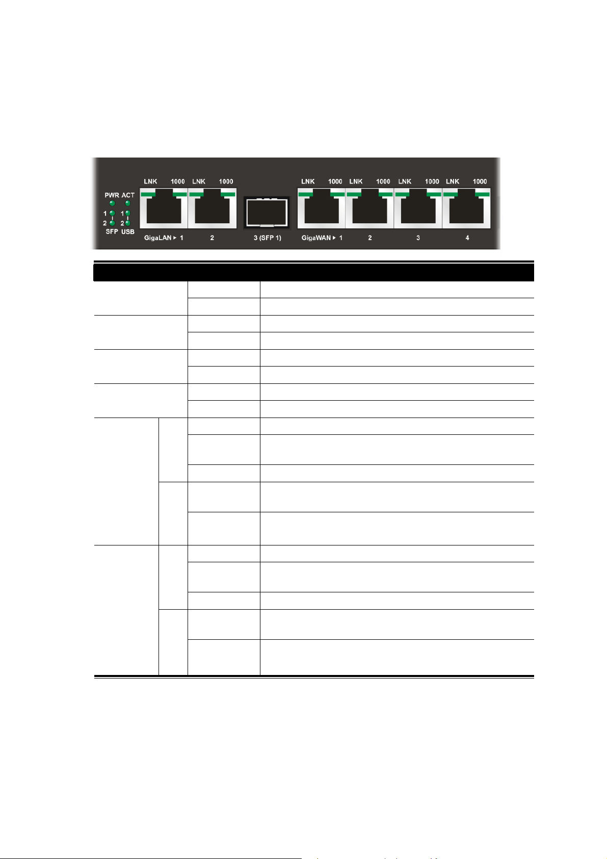
11..11 LLEEDD IInnddiiccaattoorrss aanndd CCoonnnneeccttoorrss
Before you use the Vigor router, please get acquainted with the LED indicators and connectors first.
The displays of LED indicators and connectors for the routers are different slightly.
DDeessccrriippttiioonn ffoorr LLEEDD
LED Status Explanation
GigaLAN1
/LAN 2)
1000
On The router is powered on. PWR
Off The router is powered off.
Blinking The system is active. ACT
On/Off The system is hanged.
On The fiber connection is established. SFP 1/2
Off No fiber connection is established.
On The USB device is installed and ready. USB 1/2
Off No USB device is installed.
On The Ethernet link is established on corresponding port.
Blinking The data transmission is done through the corresponding
port.
Off No Ethernet link is established.
On It means that a normal 1000 Mbps connection is through
its corresponding port.
Giga
WAN1/2/3/4
1000
Off It means that a normal 10/100 Mbps connection is
through its corresponding port.
On The Ethernet link is established.
Blinking The data transmission is done through the corresponding
port.
Off No Ethernet link is established.
On It means that a normal 1000Mbps connection is through
its corresponding port.
Off It means that a normal 10/100Mbps connection is through
its corresponding port.
2
Vigor3900 Series User’s Guide
Page 13
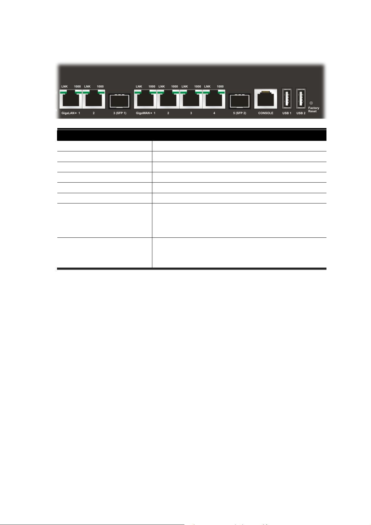
CCoonnnneeccttoorrss
Interface Description
GigaLAN1 / 2 Connecter for local network devices.
3(SFP) Connecter for fiber cable.
GigaWAN1/2/3/4 Connecter for remote network devices.
5(SFP) Connecter for fiber cable.
Console Provided for technician use.
USB1 / USB2 Connecter for the USB device.
Factory Reset Used to restore the default settings. Press it and keep for
more than 5 seconds. When you see the ACT LED begins
to blink, release the button. Then the router will restart with
the factory default configuration.
Connecter for a power cord.
ON/OFF - Power switch.
Vigor3900 Series User’s Guide
3
Page 14
11..22 HHaarrddwwaarree IInnssttaallllaattiioonn
11..22..11 NNeettwwoorrkk CCoonnnneeccttiioonn
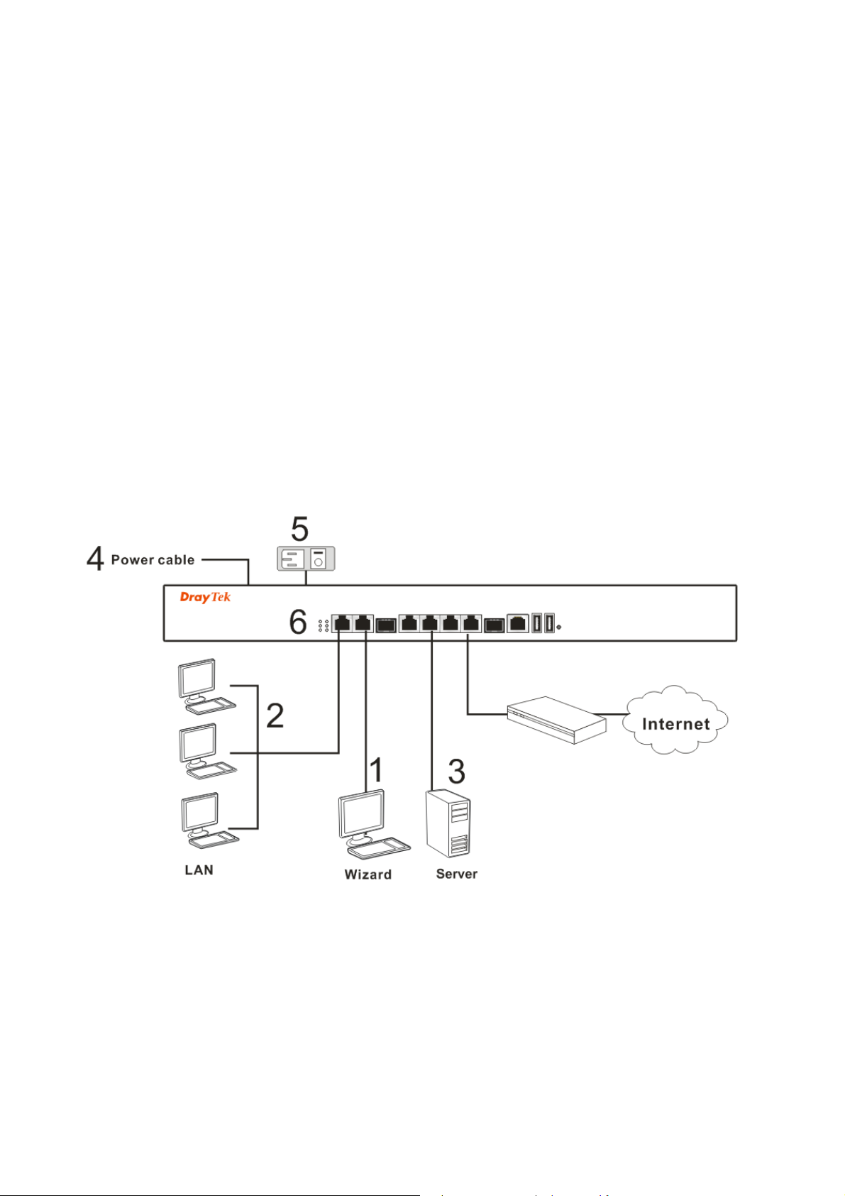
Before starting to configure the router, you have to connect your devices correctly.
1. Connect one end of an Ethernet cable (RJ-45) to one of the LAN ports of Vigor3900s.
2. Connect the other end of the cable (RJ-45) to the Ethernet port on your computer (that
device also can connect to other computers to form a small area network). The LAN
LED for that port on the front panel will light up.
3. Connect a server/modem/router (depends on your requirement) to any WAN port of
Vigor3900 with Ethernet cable (RJ-45). The WAN1 (to WAN4) LED will light up.
4. Connect the power cord to Vigor3900’s power port on the rear panel, and the other side
into a wall outlet.
5. Power on the device by pressing down the power switch on the rear panel. The PWR
LED should be ON.
6. The system starts to initiate. After completing the system test, the ACT LED will light
up and start blinking.
Below shows an outline of the hardware installation for your reference.
4
Vigor3900 Series User’s Guide
Page 15
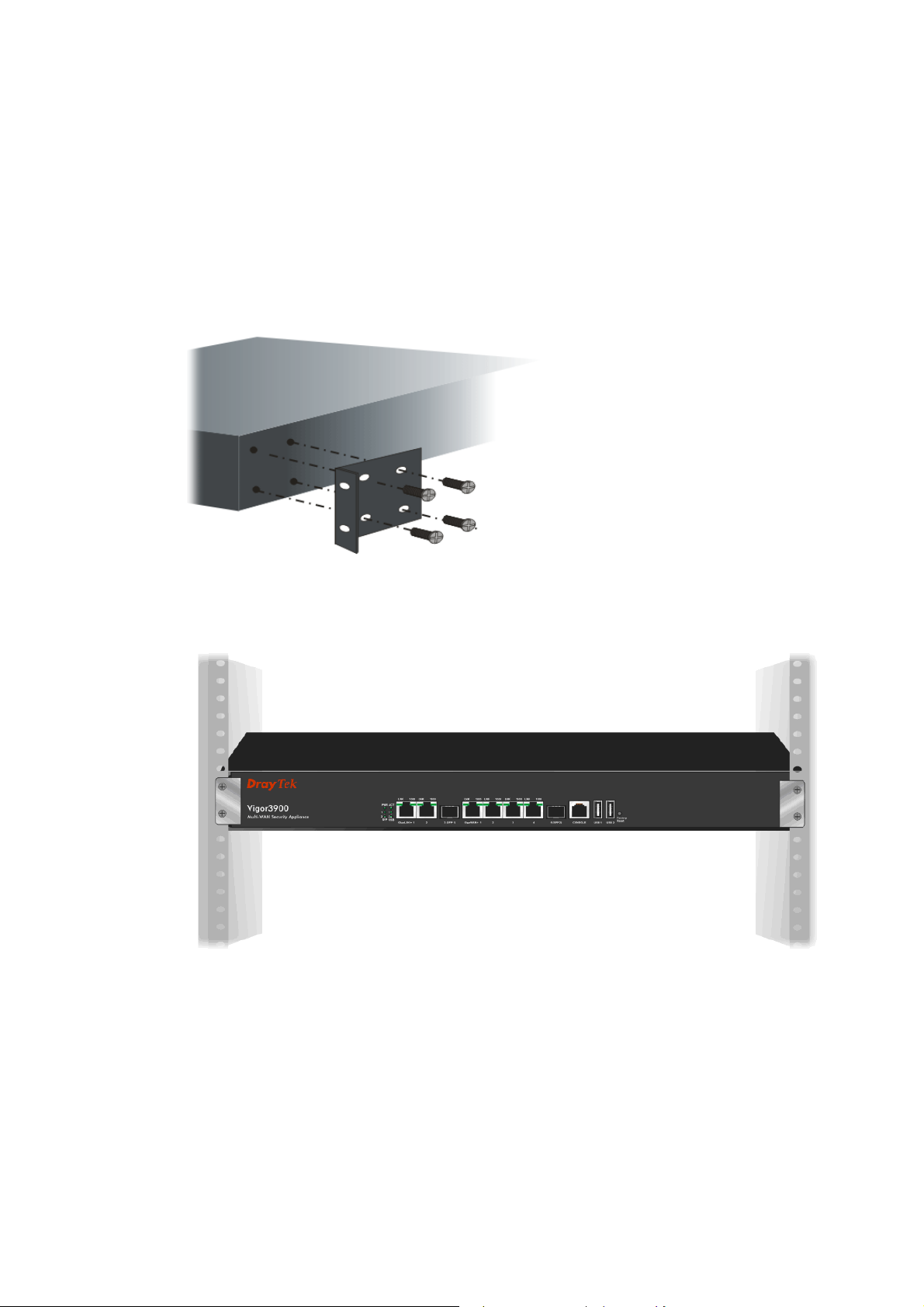
11..22..22 RRaacckk--MMoouunntteedd IInnssttaallllaattiioonn
The Vigor3900 Series can be mounted on the wall by using standard brackets shown below.
Attach the brackets to the chassis of a rack. The second bracket attaches the other side of the
chassis.
After the bracket installation, the Vigor3900 Series chassis can be installed in a rack by using
four screws for each side of the rack.
DDeesskkttoopp TTyyppee IInnssttaallllaattiioonn
Rubber pads are included with the Vigor3900 Series. These rubber pads improve the air
circulation and decrease unnecessary rubbing on the desktop.
Vigor3900 Series User’s Guide
5
Page 16

This page is left blank.
6
Vigor3900 Series User’s Guide
Page 17
Chhaapptteerr 22::
C
For use the router properly, it is necessary for you to change the password of web
configuration for security and adjust primary basic settings.
This chapter explains how to setup a password for an administrator and how to adjust basic
settings for accessing Internet successfully. Be aware that only the administrator can change
the router configuration.
22..11 CChhaannggiinngg PPaasssswwoorrdd
To change the password for this device, you have to access into the web browse with default
password first.
1. Make sure your computer connects to the router correctly.
Notice: You may either simply set up your computer to get IP
dynamically from the router or set up the IP address of the computer to be
the same subnet as the default IP address of Vigor router 192.168.1.1.
For the detailed information, please refer to the later section - Trouble
Shooting of this guide.
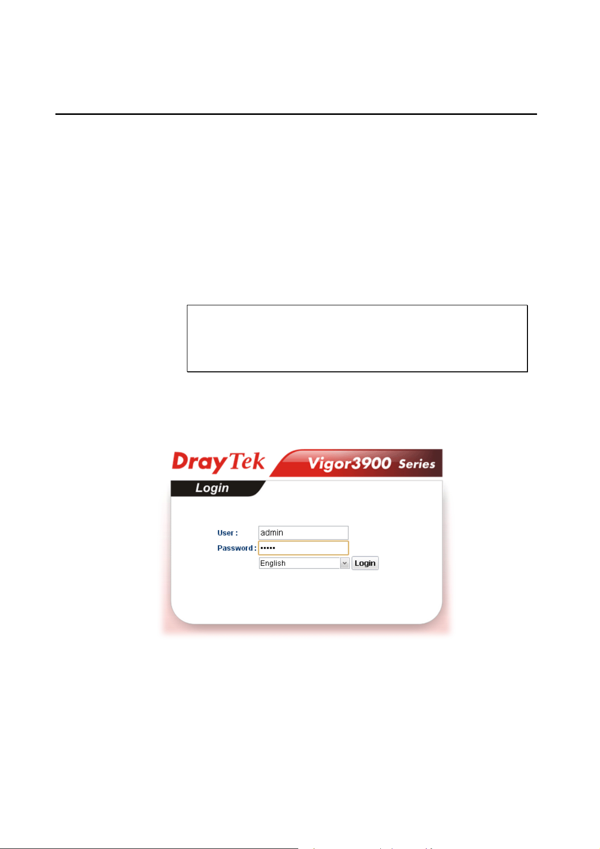
2. Open a web browser on your PC and type http://192.168.1.1. A pop-up window will
open to ask for username and password. Please type default values on the window for
the first time accessing. The default value for user name is admin and the password is
admin. Next, click Login.
Baassiicc
B
Seettuupp
S
Vigor3900 Series User’s Guide
7
Page 18
3. Now, the Main Screen will pop up.
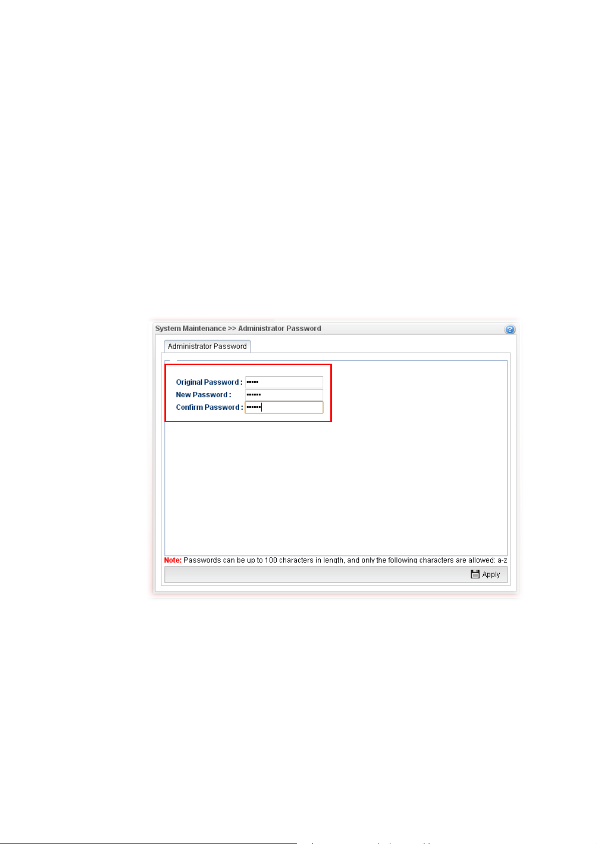
4. Go to System Maintenance page and choose Administrator Password.
5. Enter the login password (admin) on the field of Original Password. Type a new one
in the field of New Password and retype it on the field of Confirm Password. Then
click Apply to continue.
6. Now, the password has been changed. Next time, use the new password to access the
Web User Interface for this router.
8
Vigor3900 Series User’s Guide
Page 19
22..22 QQuuiicckk SSttaarrtt WWiizzaarrdd
Quick Start Wizard is a wizard which is designed for configuring your router accessing Internet with simply steps. In the Quick Start Wizard group, you can configure the router to access the Internet with different modes such as Static, DHCP, PPPoE, or PPTP modes.
For most users, Internet access is the primary application. The router supports the Ethernet
WAN interface for Internet access.
Click Quick Start Wizard from the home page. Quick Start Wizard will guide the user to
establish LAN interface profile, WAN interface profile and select proper protocol for
connection. The following will explain in more detail for the various broadband access
configurations.
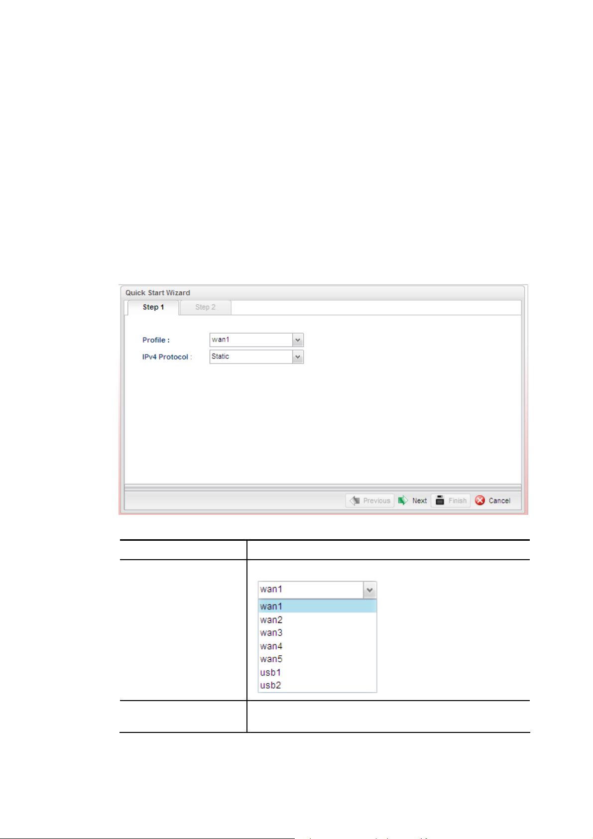
22..22..11 SStteepp 11 -- SSppeecciiffyyiinngg tthhee WWAANN PPrrooffiillee
In the first page of Quick Start Wizard, please create a WAN profile.
Available settings are explained as follows:
Item Description
Profile
IPv4 Protocol
Vigor3900 Series User’s Guide
Use the drop down list to choose one WAN profile.
Use the drop down list to choose a connection mode for such
WAN profile.
9
Page 20
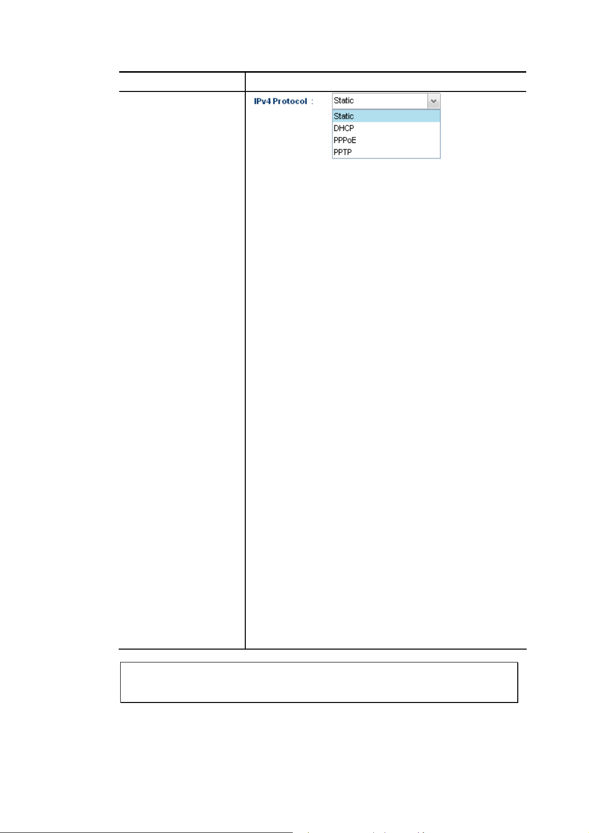
Item Description
Static - If Static is selected, you can manually assign a static
IP address to the WAN interface and complete the
configuration by applying the settings.
DHCP - It allows a user to obtain an IP address automatically
from a DHCP server on the Internet. If you choose
DHCP mode, the DHCP server of your ISP will
assign a dynamic IP address for Vigor3900
automatically. It is not necessary for you to assign
any setting. (Host Name and Domain Name are
required for some ISPs).
PPTP - This mode lets user get the IP group information by a
DSL modem with PPTP service from ISP. Your
service provider will give you user name, password,
and authentication mode for a PPTP setting. Click
PPTP as the protocol. Type in all the information
that your ISP provides for this protocol.
If your ISP offers you PPTP (Point-to-Point
Tunneling Protocol) mode, please select PPTP for
this router. Next, enter the required information
provided by your ISP on the web page.
PPPoE - PPPoE stands for Point-to-Point Protocol over
Ethernet. It relies on two widely accepted standards:
PPP and Ethernet. It connects users through an
Ethernet to the Internet with a common broadband
medium, such as a single DSL line, wireless device
or cable modem. All the users over the Ethernet can
share a common connection.
PPPoE is used for most of DSL modem users. All
local users can share one PPPoE connection for
accessing the Internet. Your service provider will
provide you information about user name, password,
and authentication mode.
If your ISP provides you the PPPoE (Point-to-Point
Protocol over Ethernet) connection, please select
PPPoE for this router to get the following page.
Enter the username and password provided by your
ISP on the web page.
Note: After you creating the WAN profile(s) by using Quick Start Wizard, you can
select the existing WAN profiles for next time. Simply use the drop down list to choose
the WAN profile available for modifying.
When you finish the above settings, please click Next to go to next page.
10
Vigor3900 Series User’s Guide
Page 21
22..22..22 SStteepp 22 -- CCoonnffiigguurriinngg tthhee SSeelleecctteedd PPrroottooccooll
This page will be changed according to the IPv4 Protocol Type selected on last page.
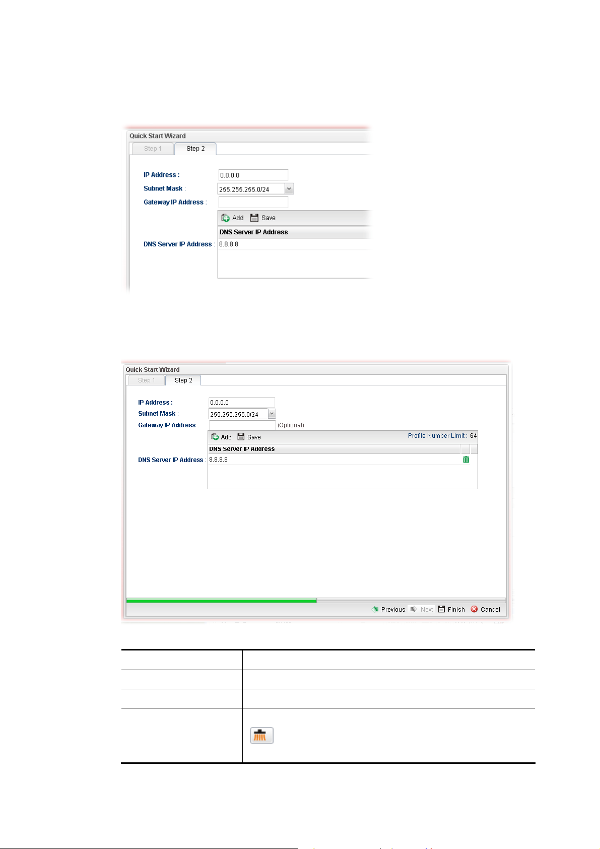
IIff SSttaattiicc iiss sseelleecctteedd
If Static is selected, the following screen will appear. You can manually assign a static IP
address to the WAN interface and complete the configuration by applying the settings.
Available parameters are listed as follows:
Item Description
IP Address
Subnet Mask
Gateway IP Address
Vigor3900 Series User’s Guide
Type a public IP address for such WAN profile.
Choose the static mask from the drop down list.
Type a public gateway address for such WAN profile.
- click it to remove the created IP address if you are not
satisfied with it.
11
Page 22
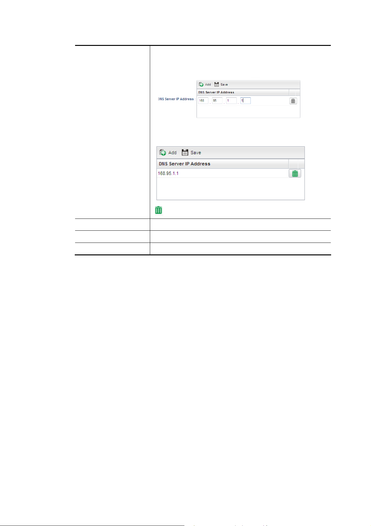
DNS Server IP
Address
Previous
Add – Click this button to display the IP address field for
adding a new IP address. Type the IP address on the tiny
boxes one by one.
Save – After finished the IP address configuration, click Save
to save the setting onto the router.
– Click the icon to remove the selected entry.
Click it to return to previous setting page.
Finish
Cancel
Click it to finish the configuration.
Click it to discard the settings configured in this page.
When you finished the above settings, please click Finish.
12
Vigor3900 Series User’s Guide
Page 23
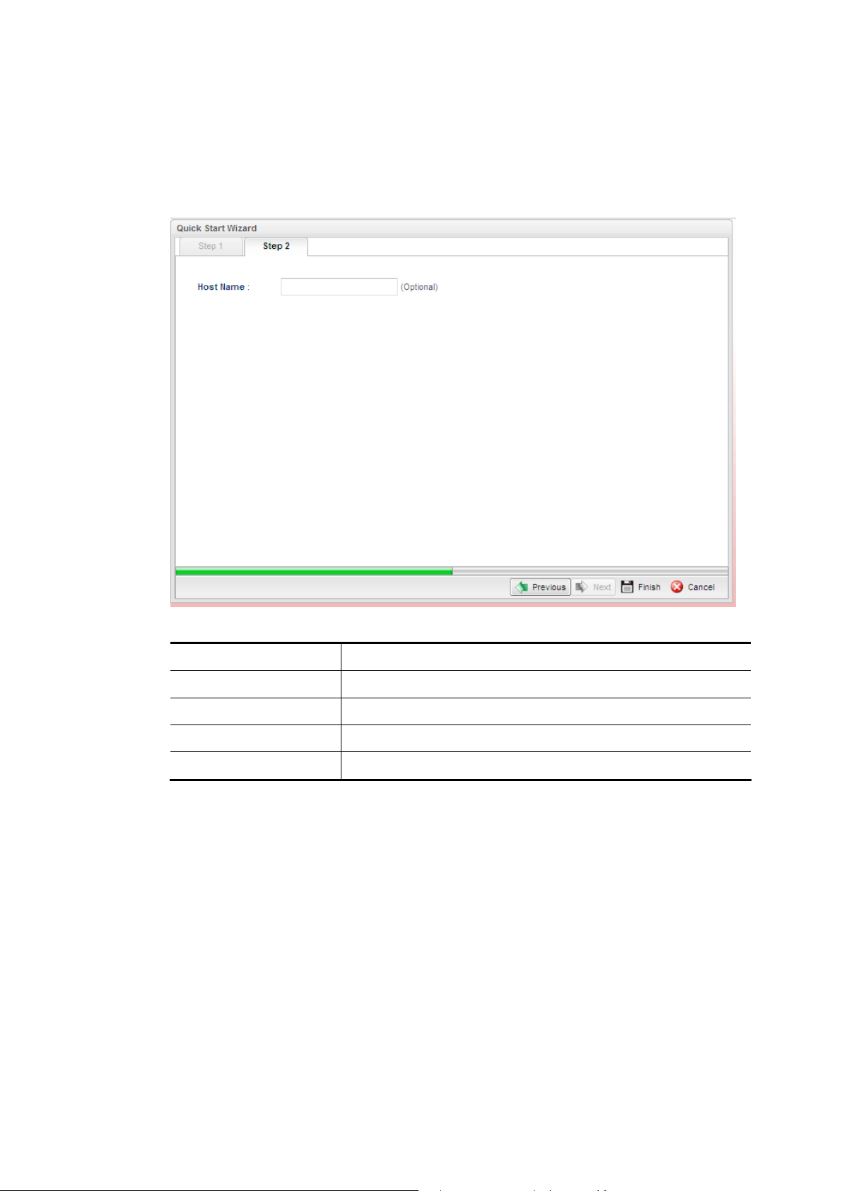
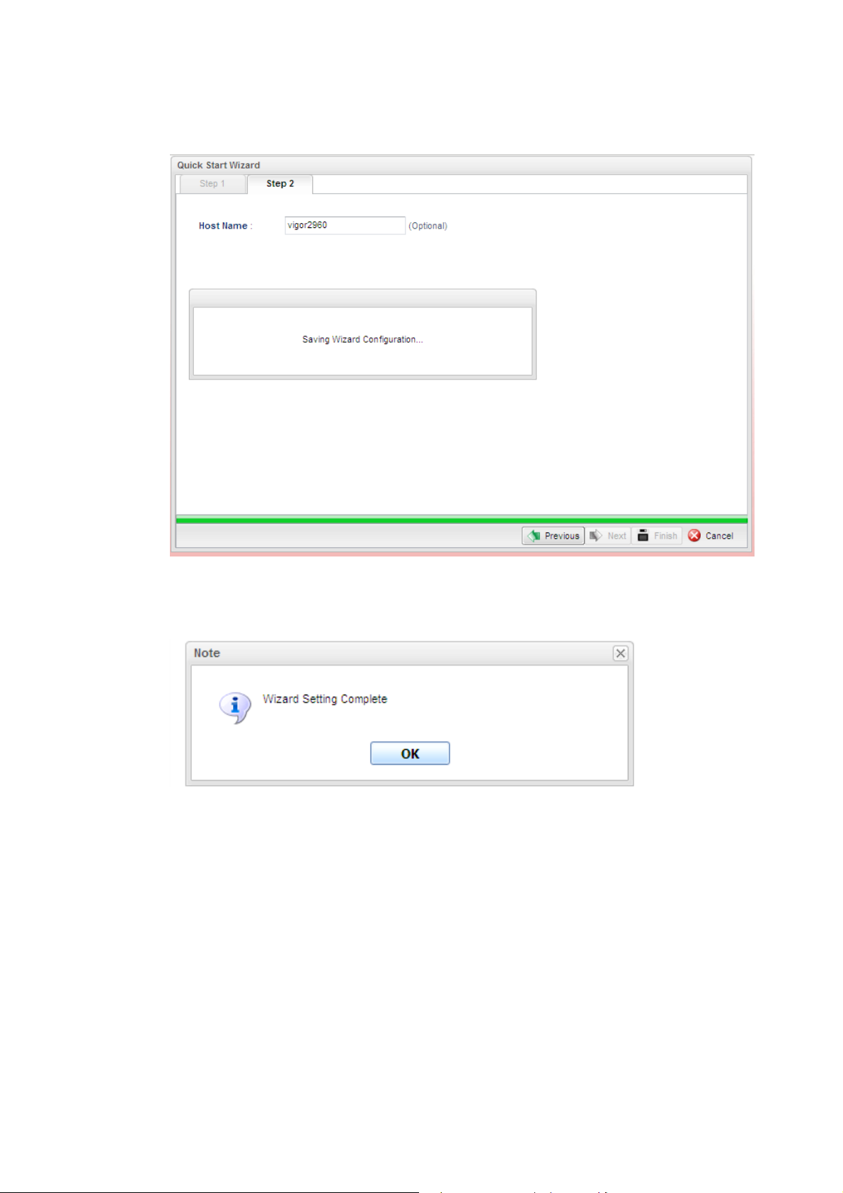
IIff DDHHCCPP iiss sseelleecctteedd
DHCP allows a user to obtain an IP address automatically from a DHCP server on the
Internet. If you choose DHCP mode, the DHCP server of your ISP will assign a dynamic IP
address for Vigor3900 automatically. It is not necessary for you to assign any setting. (Host
Name is required for some ISPs).
Available parameters are listed as follows:
Item Description
Host Name (Optional)
Previous
Finish
Cancel
Type a name as the host name for identification.
Click it to return to previous setting page.
Click it to finish the configuration.
Click it to discard the settings configured in this page.
When you finished the above settings, please click Finish.
IIff PPPPPPooEE iiss sseelleecctteedd
PPPoE stands for Point-to-Point Protocol over Ethernet. It relies on two widely accepted
standards: PPP and Ethernet. It connects users through an Ethernet to the Internet with a
common broadband medium, such as a single DSL line, wireless device or cable modem. All
the users over the Ethernet can share a common connection.
PPPoE is used for most of DSL modem users. All local users can share one PPPoE
connection for accessing the Internet. Your service provider will provide you information
about user name, password, and authentication mode.
If your ISP provides you the PPPoE (Point-to-Point Protocol over Ethernet) connection,
please select PPPoE for this router to get the following page. Enter the username and
password provided by your ISP on the web page.
Vigor3900 Series User’s Guide
13
Page 24
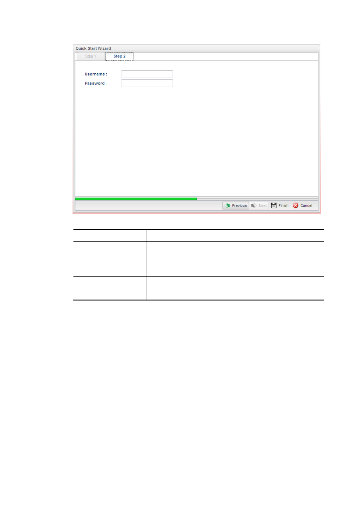
Available parameters are listed as follows:
Item Description
Username
Password
Previous
Finish
Cancel
Type in the username provided by ISP in this field.
Type in the password provided by ISP in this field.
Click it to return to previous setting page.
Click it to finish the configuration.
Click it to discard the settings configured in this page.
When you finished the above settings, please click Finish.
14
Vigor3900 Series User’s Guide
Page 25
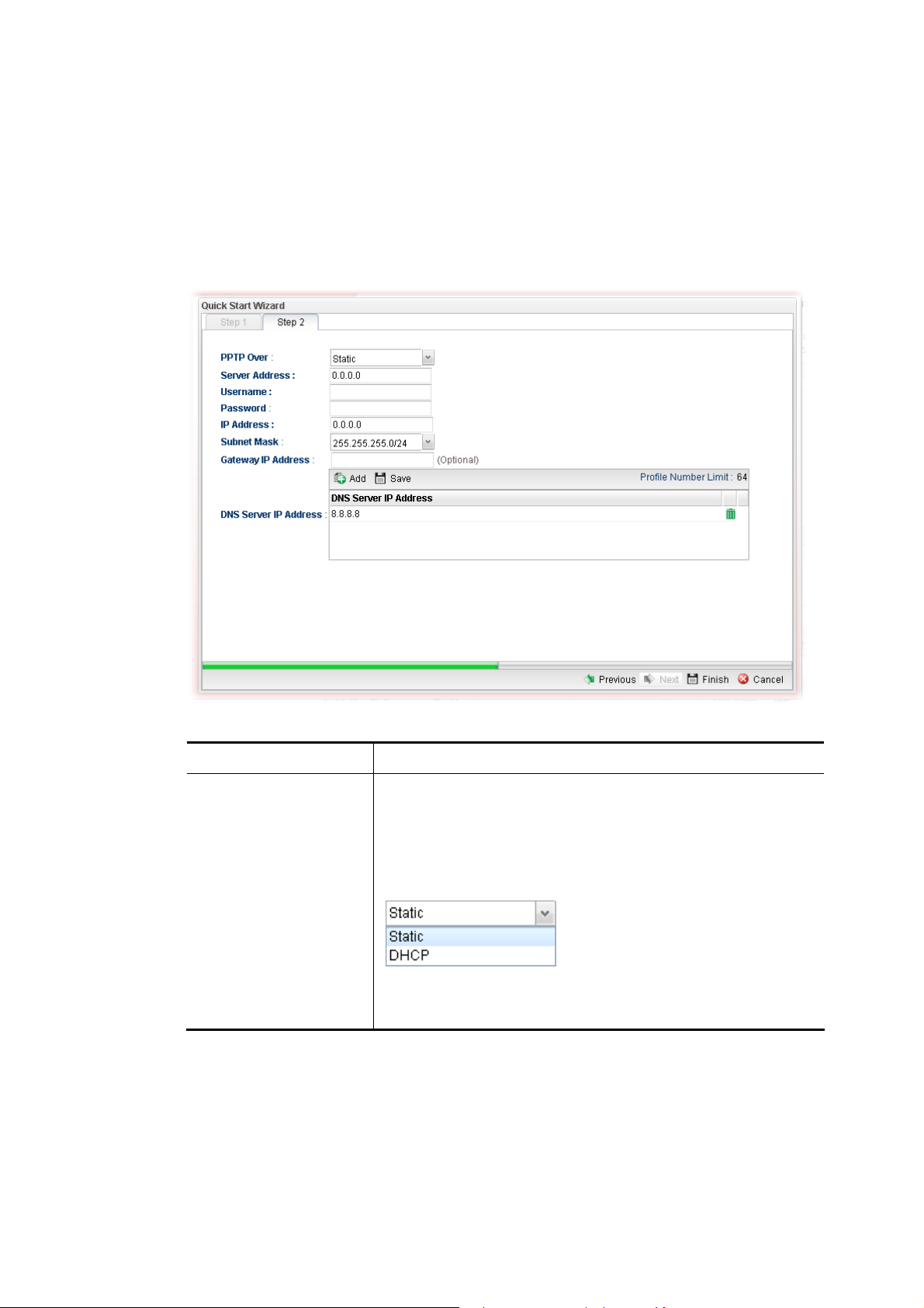
IIff PPPPTTPP iiss sseelleecctteedd
This mode lets user get the IP group information by a DSL modem with PPTP service from
ISP. Your service provider will give you user name, password, and authentication mode for a
PPTP setting. Click PPTP as the protocol. Type in all the information that your ISP provides
for this protocol.
If your ISP offers you PPTP (Point-to-Point Tunneling Protocol) mode, please select PPTP
for this router. Next, enter the settings provided by your ISP on the web page.
Available parameters are listed as follows:
Item Description
PPTP Over
Usually ISP dynamically assigns IP address to you each time
you connect to it and request. In some case, your ISP provides
service to always assign you the same IP address whenever
you request. In this case, you can fill in this IP address in the
Fixed IP field. Please contact your ISP before you want to
use this function.
Static – specify the IP address.
DHCP - obtain the IP address automatically.
Vigor3900 Series User’s Guide
15
Page 26
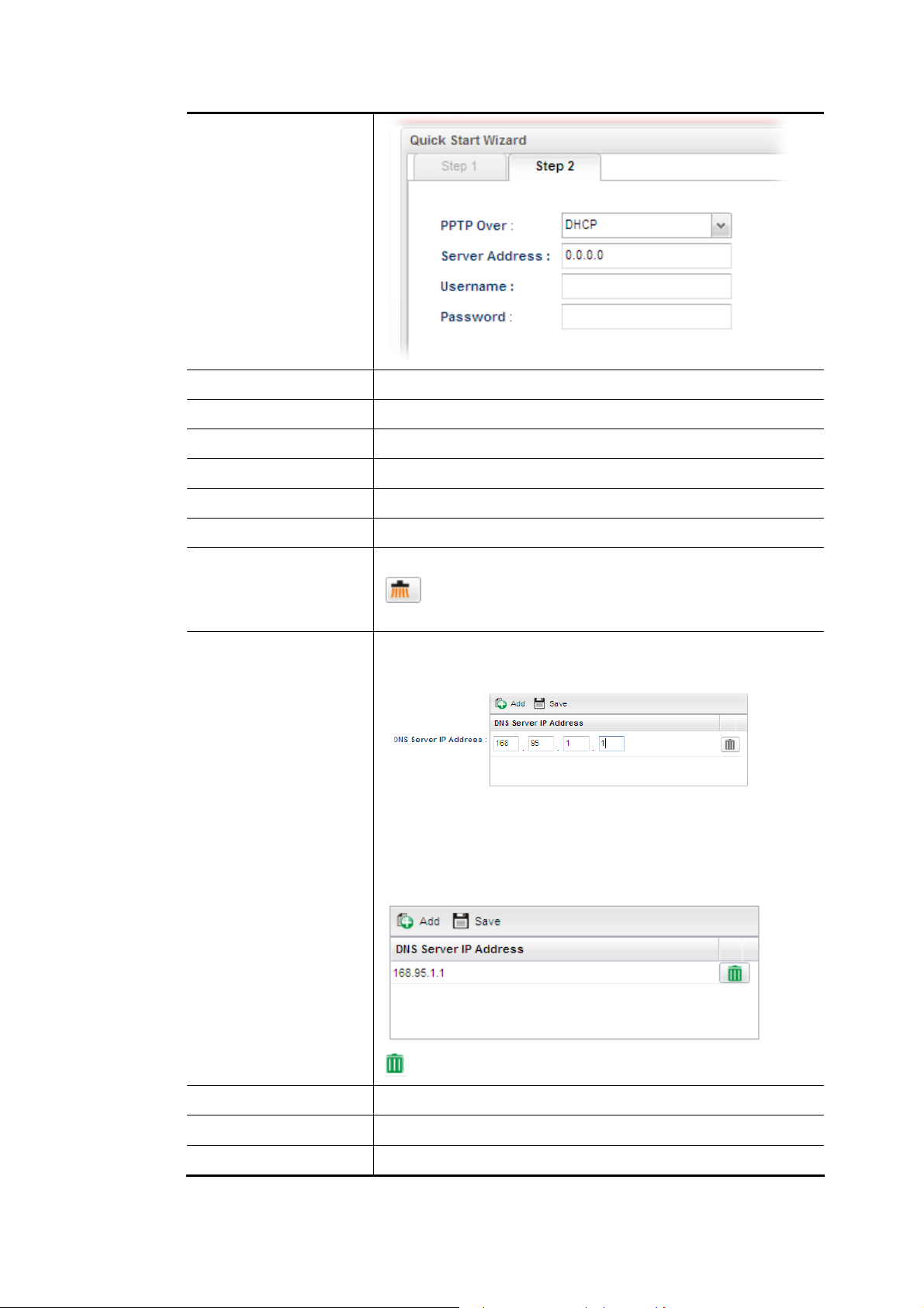
Server Address
Type a remote IP address of PPTP server.
Username
Password
Previous
IP Address
Subnet Mask
Gateway IP Address
DNS Server IP
Address
Type in the username provided by ISP in this field.
Type in the password provided by ISP in this field.
Click it to return to previous setting page.
Type a public IP address for such WAN profile.
Choose the static mask from the drop down list.
Type a public gateway address for such WAN profile.
- click it to remove the IP address if you are not satisfied
with it.
To add a new IP address, simply place the mouse cursor on
this filed. The following dialog will appear.
Add – Click this button to display the IP address field for
adding a new IP address.
Save – After finished the IP address configuration, click Save
to save the setting onto the router.
Previous
Finish
Cancel
– Click the icon to remove the selected entry.
Click it to return to previous setting page.
Click it to finish the configuration.
Click it to discard the settings configured in this page.
16
Vigor3900 Series User’s Guide
Page 27
When you finished the above settings, please click Finish. Later, you can surf the Internet at
any time.
When the following screen appears, it means you have finished the Quick Start Wizard
configuration.
Vigor3900 Series User’s Guide
17
Page 28
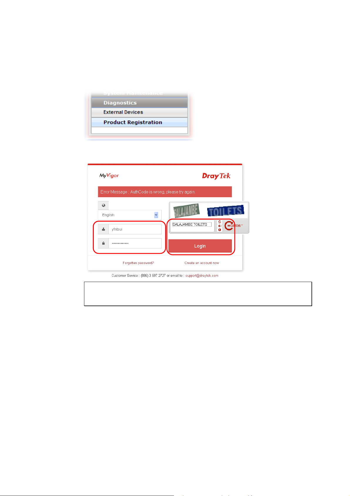
22..33 RReeggiisstteerr VViiggoorr RRoouutteerr
Please follow the steps below to register the router.
1 Before using such function, please register your router online first. Log into the Web
User Interface of Vigor3900 and click Product Registration.
2 A Login page will be shown on the screen. Please type the account and password that
you created previously. And click Login.
Note: If you haven’t an accessing account, please create a new one first. Please read
the articles on the Agreement regarding user rights carefully while creating a
user account.
18
Vigor3900 Series User’s Guide
Page 29
3 The following page will be displayed after you logging in MyVigor. From this page,
please click Add.
4 When the following page appears, your router information has been added to the
database.
5 After clicking OK, you will see the following page. Your router has been registered to
myvigor website successfully.
Vigor3900 Series User’s Guide
19
Page 30

This page is left blank.
20
Vigor3900 Series User’s Guide
Page 31

Chhaapptteerr 33::
C
Tuuttoorriiaall
T
33..11 HHooww ttoo uussee BBaannddwwiiddtthh LLiimmiitt oonn VViiggoorr33990000??
Bandwidth Limit feature enables Network Administrator to limit the amount of data that a
LAN client can transfer over a period of time. This will prevent the router's resources from
being taken up by only a few LAN clients. We can also create customized Bandwidth Limit
rule for each LAN client. This note demonstrates how to set up Bandwidth Limit with
Vigor3900.
1. Go to Bandwidth Management >> Bandwidth Limit and click “Add” to start the
configuration.
Apppplliiccaattiioonn aanndd
A
2. Then set up the details for the new rule.
Vigor3900 Series User’s Guide
21
Page 32

Enter the profile name.
Enable the profile.
Set the customized TX Limit and RX Limit for transmission rate.
Enable Each or Shared Mode.
Each: Bandwidth Limit for each LAN Client
Shared: Bandwidth Limit for a group of LAN Clients
Go to source target and click “+” icon to set the rule for particular IP address.
Click Apply to save.
3. Bandwidth Limit can also be used with a time schedule to restrict LAN clients only at a
certain time.
22
Vigor3900 Series User’s Guide
Page 33

Go to generate target >> Time Object.
Click “+” icon to setup the time schedule.
Set profile name, frequency, data and time.
Click Apply to save.
4. Furthermore, you may enable Default Session Limit to apply session limit to all the
other unspecified LAN clients.
5. We can also enable Smart Bandwidth Limit to restrict the bandwidth of unspecified
LAN clients only when their session number is over the threshold.
6. Data Flow Monitor can be used to check the status of Bandwidth Limit. Go to
Diagnostics >> Data Flow Monitor and enable the monitor then we can check the
transmission rate displayed on the screen.
Vigor3900 Series User’s Guide
23
Page 34

33..22 HHooww ttoo uussee SSeessssiioonn LLiimmiitt oonn VViiggoorr33990000??
Session Limit feature enables Network Administrator to limit the number of sessions that a
LAN client can use. This will prevent the router's resources from being taken up by, for
example, P2P applications. We can also create customized Session Limit rule for each LAN
client. This note demonstrates how to set up Session Limit with Vigor3900.
1. Go to Bandwidth Management >> Session Limit and click “Add” to create a new
rule.
2. Then set up the details for the new rule.
Enter the profile name.
Enable the profile.
Set the customized max session.
Go source target and click the “+” icon to set the rule for particular IP address.
24
Vigor3900 Series User’s Guide
Page 35

3. Session Limit can also be used with time schedule to restrict sessions only at a certain
time.
Go to generate target.
Click “+” icon to setup the time schedule.
Set profile name, frequency, date, and time.
Click Apply to save.
4. Furthermore, you may enable Default Session Limit to apply session limit to all other
unspecified LAN clients.
Enable Default Session Limit.
Customize your Default Max Sessions.
Click Apply to save.
5. Go to Diagnostics >> Data Flow Monitor and enable the monitor then we can check
how many sessions a specific LAN client use.
Vigor3900 Series User’s Guide
25
Page 36

33..33 HHooww ttoo aassssiiggnn ootthheerr IIPP aass GGaatteewwaayy IIPP ffoorr LLAANN DDHHCCPP
cclliieennttss??
While Vigor3900 acts as DHCP Server, it will assign its LAN IP as the Gateway IP to
DHCP clients by default. Then DHCP clients will use Vigor3900 as Default Gateway for
accessing the Internet. However, in some cases, network administrator would like Vigor3900
to be the DHCP server but use another LAN router as Internet Gateway for LAN hosts. This
document introduces how to achieve the purpose and below is the scenario:
1. Go to LAN >> General Setup >> lan1 click Edit, input the Gateway IP you'd like to
assign to DHCP clients in DHCP Routers field and then Apply it.
26
Vigor3900 Series User’s Guide
Page 37

2. Then, run “cmd” to open Command Prompt on a PC (DHCP client), then use
command “ipconfig/release” and “ipconfig/renew” to get an IP address again, and
check if it obtains the configured Gateway IP.
3. Now, this PC will access the Internet through Gateway IP 10.150.55.2! But what
should we do if we want this PC to be able to access the remote VPN network
connected through Vigor3900? It requires to specify Vigor3900's IP as the gateway to
remote VPN Network, there are two ways to do this:
a. Add Static Route on the PC by command “ip route add 172.16.2.0 mask
255.255.255.0 10.150.55.1 -p” Where 172.16.2.0 mask 255.255.255.0 is the IP
address of remote VPN Network, 10.150.55.1 is the LAN IP of Vigor2960.
b. Add a Static Route on the Gateway Router 10.150.55.2.
Vigor3900 Series User’s Guide
27
Page 38

33..44 HHooww ttoo uussee PPoorrtt RReeddiirreeccttiioonn oonn VViiggoorr33990000??
Port Redirection allows Internet clients to access server behind router on a certain port of
router's WAN IP. This note is going to demonstrate how to use this feature with the
following topology in Vigor3900.
1. Go to NAT >> Port Redirection, click Add to create a profile.
2. Edit the profile.
Give profile name and enable it.
Select “One to One” as Port Redirection Mode.
Select Protocol.
Enter Public Port as the port to which Internet client should connect.
Enter Private IP as the IP of the server on LAN.
Enter Private Port as the port to which the server is listening.
Click Add in More Port to allow more public ports to be redirected to other
private ports.
28
Vigor3900 Series User’s Guide
Page 39

3. Now, we can access the server behind NAT(Vigor3900) from Vigor3900's WAN IP
with the specified port.
Vigor3900 Series User’s Guide
29
Page 40

33..55 HHooww ttoo CCoonnffiigguurree OOSSPPFF??
OSPF (Open Shortest Path First) uses the algorithm of SPF (Shortest Path First) to calculate
the route metric. It is suitable for large network and complicated data exchange. Both
Vigor2960 and Vigor3900 support up to OSPF version 2(only for IPv4).
The Autonomous System (AS) used in OSPF indicates the largest entity and can be divided
into several areas. Usually, Area 0 will be used as OSPF backbone which distributing the
routing information among areas.
When you need faster convergence than distance vector, want to support much larger
networks or want to have less susceptible to bad routing information, you can enable OSPF
feature to fit your request. Note that both routers must support OSPF function at the same
time to build the OSPF connection.
In the following example, a PC can go 192.168.2.0/24 and 192.168.4.0/24 without setting
any Static Route. Refer to the OSPF topology diagram listed below.
OSPF can place each router (e.g., Vigor3900A, Vigor3900B and Vigor2960 shown above) at
the root of a tree and calculate the shortest path to each destination according to the
cumulative cost to reach the destination.
Each router has its own view of the topology and calculates its own SPF tree, even though all
the routers build a shortest-path tree using the same link-state database.
30
Vigor3900 Series User’s Guide
Page 41

CCoonnffiigguurraattiioonn ffoorr VViiggoorr33990000 AA,,
1. Open LAN >> General Setup to create a LAN (192.168.1.1/24) profile named lan1
with the settings shown below.
2. Next, continue to create a LAN (192.168.3.1/24) profile named lan2 with the settings
shown below.
3. Open LAN >> Static Route and click the Inter-LAN Route tab to enable this profile.
Vigor3900 Series User’s Guide
31
Page 42

4. Open LAN >> OSPF Configuration to enable this profile. Click Add to make the LAN
Profiles lan2 area setting as 11 and lan1 area as 11. (As shown in the topology diagram.)
CCoonnffiigguurraattiioonn ffoorr VViiggoorr33990000 BB,,
1. Open LAN >> General Setup to create a LAN (192.168.2.1/24) profile named lan1
with the settings shown below.
2. Next, continue to create a LAN (192.168.3.2/24) profile named lan2 with the settings
shown below.
32
Vigor3900 Series User’s Guide
Page 43

3. Open LAN >> Static Route and click the Inter-LAN Route tab to enable this profile.
4. Open LAN >> OSPF Configuration to enable this profile. Click Add to make the LAN
Profiles lan2 area setting as 11 and lan1 area as 11. (As shown in the topology diagram.)
CCoonnffiigguurraattiioonn ffoorr VViiggoorr22996600,,
1. Open LAN >> General Setup to create a LAN (192.168.4.1/24) profile named lan1
with the settings shown below.
Vigor3900 Series User’s Guide
33
Page 44

2. Next, continue to create a LAN (192.168.3.3/24) profile named lan2 with the settings
shown below.
3. Open LAN >> Static Route and click the Inter-LAN Route tab to enable this profile.
4. Open LAN >> OSPF Configuration to enable this profile. Click Add to make the LAN
Profiles lan2 area setting as 11 and lan1 area as 11. (As shown in the topology diagram.)
34
Vigor3900 Series User’s Guide
Page 45

5. After setting, check the routing information (marked with red line) which is created by
OSPF.
RRoouuttiinngg iinnffoorrmmaattiioonn ffoorr VViiggoorr33990000 AA
RRoouuttiinngg iinnffoorrmmaattiioonn ffoorr VViiggoorr33990000 BB
RRoouuttiinngg iinnffoorrmmaattiioonn ffoorr VViiggoorr22996600
Vigor3900 Series User’s Guide
35
Page 46

33..66 HHooww ttoo CCoonnffiigguurree LLAANN ttoo LLAANN IIPPSSeecc TTuunnnneell bbeettwweeeenn
VViiggoorr33990000 aanndd OOtthheerr RRoouutteerr ((MMaaiinn MMooddee))
Here provides an example about LAN to LAN IPSec tunnel established between Vigor3900
and Vigor2710.
CCoonnffiigguurriinngg VViiggoorr33990000
1. Access into the Web User Interface of Vigor3900 and open VPN and Remote Access
>> LAN to LAN Profiles to add a new VPN configuration.
Type the Pre-shared key and choose a WAN Profile. Specify Local IP/Subnet Mask
with 192.168.29.0/24. The Remote Host should be Vigor 2710's WAN IP address; and
the Remote IP/Subnet Mask should be192.168.2.0/24.
2. Click Apply to save the settings and return to previous page.
36
Vigor3900 Series User’s Guide
Page 47

0
CCoonnffiigguurriinngg VViiggoorr2277110
1. In Vigor2710, it is necessary to build two VPN connections (for two WANs) to connect
with Vigor3900. Please open the Web User Interface of Vigor2710 and open VPN and
Remote Access >> LAN to LAN.
First, please type the name of such VPN connection in the field of Profile Name
(e.g., 3900).
Check the box of Enable this profile.
Choose Dial-Out as Call Direction and check the box of Always on.
2. For Dial-Out Settings, please choose IPSec Tunnel and type WAN IP address of
Vigor3900 in the field of Server IP/Host Name for VPN (e.g., 1.169.162.1). Type the
same IKE Pre-Shared Key configured in Vigor3900.
Vigor3900 Series User’s Guide
37
Page 48

3. For the role of Vigor2710 is dialing-out, please skip Dial-In setting. Type the Remote
Network IP and Remote Network Mask of Vigor3900 to complete configuration.
4. Please check if the VPN connection is built successfully in both devices respectively.
For Vigor3900, open VPN and Remote Access>>IPSec>>Status for viewing the
result.
As to Vigor2710, please open VPN and Remote Access>>Connection Management
to confirm the result.
38
Vigor3900 Series User’s Guide
Page 49

33..77 HHooww ttoo rruunn RRDDPP sseerrvviiccee iinn tthhee bbrroowwsseerr vviiaa llooggggiinngg iinn 33990000''ss
HHTTTTPPSS SSeerrvveerr??
1. Open the Web User Interface of Vigor3900.
2. Enable the HTTPS service from System Maintenance >> Access Control by clicking
Remote Desktop Protocol (RDP) is a protocol designed for secure communications in
networks using Microsoft Terminal Services. An easy way is provided to establish
connection between the router and the RDP Server via any browser.
Enable for HTTPS Allow and type 443 as the value of HTTPS Port.
Vigor3900 Series User’s Guide
39
Page 50

3. Open SSL VPN >> SSL Application and click the RDP tab to create a profile named
“Win7”. Type IP address, Port number, and Screen Size as you want, then click Apply
to save the settings.
4. Open User Management >> User Profile to create a new profile named “7788”. Set
the Password as 7788 and choose the profile of Win7 as SSL Application (RDP).
Click Apply.
5. Logout Vigor3900.
40
Vigor3900 Series User’s Guide
Page 51

6. Login Vigor3900 HTTPS Server with 7788 for both Username and Password.
7. A screen like the following figure will appear. Simply click the SSL Application link.
8. In the following screen, click Connect for connecting to Win7, the RDP server.
Vigor3900 Series User’s Guide
41
Page 52

9. After that, you can access into Windows 7 via a browser. Note the message below the
window. In which, TLS means Transport Layer Security.
42
Vigor3900 Series User’s Guide
Page 53

Troubleshooting
If you have installed Java Runtime Environment edition 6 but still cannot establish the
connection, please make sure you have disabled “Use TLS 1.0” in the Java Control Panel
as figure shown below. Then, try to connect again.
Vigor3900 Series User’s Guide
43
Page 54

33..88 HHooww ttoo CCoonnffiigguurree VVPPNN LLooaadd BBaallaannccee bbeettwweeeenn VViiggoorr33990000
aanndd OOtthheerr RRoouutteerr
The staff in branch office can access into mail server/FTP server installed in the headquarters
via VPN Load Balance tunnels. Refer to the following figure.
Vigor3900 allows users to build VPN load balance connection between Vigor3900 and other
router. Take Vigor2950 for an example. There are two WANs on Vigor2950 and two WANs
on Vigor3900. We will build VPN connection with load balance between Vigor3900 and
two WANs of Vigor2950 respectively.
CCoonnffiigguurriinngg VViiggoorr33990000
1. Access into the Web User Interface of Vigor3900 and open VPN and Remote Access
>> VPN Profiles to add new VPN profiles. Click Add.
44
Vigor3900 Series User’s Guide
Page 55

2. Create a profile for WAN 1 (named 2950WAN1). Type the settings as shown below:
Vigor3900 Series User’s Guide
45
Page 56

3. Click Apply to save the settings and exit the dialog.
4. Create a profile for WAN 2 (named 2950WAN2).
46
Vigor3900 Series User’s Guide
Page 57

5. Click Apply to save the settings and exit the dialog.
6. Open VPN and Remove Access>>VPN Trunk Management and click the Load
Balance Pool tab. Click Add to add a Load Balance Pool profile.
7. The following window will pop up. Give a name for the profile.
8. Click the Load Balance tab. Select the IPSec GRE profiles (e.g., 2950WAN1) set for
Vigor2950 then click Apply.
Vigor3900 Series User’s Guide
47
Page 58

9. Click the Load Balance Rule tab and click Add to add a Load Balance rule profile.
10. Enable this profile and input the following settings then click Apply.
Type the local network IP address and Mask of Vigor3900 as Source IP Address and
Source Mask; type the network IP and Mask of Vigor2950 as Destination IP Address &
Destination Mask. Select the Load Balance Pool profile (e.g., 2950_LB) set for
Vigor2950.
48
Vigor3900 Series User’s Guide
Page 59

CCoonnffiigguurriinngg VViiggoorr22995500
1. In Vigor2950, it is necessary to build two VPN connections (for two WANs) to connect
with Vigor3900. Please open the Web User Interface of Vigor2950 and open VPN and
Remote Access >> LAN to LAN.
First, please type the name of such VPN connection in the field of Profile Name
(e.g., 3900WAN1).
Choose WAN1 Only as VPN Dial-Out Through setting to specify which WAN
interface will be used for building VPN connection.
Choose Dial-Out as Call Direction and check the box of Always on.
For Dial-Out Settings, please choose IPSec Tunnel and type WAN IP address of
Vigor3900 in the field of Server IP/Host Name for VPN (e.g., 29.29.29.1). Type
the same IKE Pre-Shared Key configured in Vigor3900.
For the role of Vigor2950 is dialing-out, please skip Dial-In setting. In this
example, please type the 1.1.1.1 in the field of My GRE IP; and type the GRE IP
address 1.1.1.2 in the field of Peer GRE IP.
Vigor3900 Series User’s Guide
49
Page 60

Please type the network IP address and subnet of Vigor3900 in the field of
Remote Network IP and Remote Network Mask. Type the network IP address and
subnet of Vigor2950 in the field of Local Network IP and Local Network Mask.
2. Continue to set the second VPN connection (profile name is 3900WAN2). The first
VPN tunnel will be used by WAN1 of Vigor2950. The second VPN tunnel will be
configured for the WAN2 of Vigor2950. Therefore, please choose WAN2 Only for
VPN Dial-Out Through.
Choose IPSec Tunnel and type the Server IP and Pre-shared Key as shown
below.
In the field of GRE over IPSec, please type the corresponding settings for
Vigor3900. Refer to the following figure.In this example, please type the 2.2.2.1
in the field of My GRE IP; and type the GRE IP address 2.2.2.2 in the field of
Peer GRE IP.
50
Vigor3900 Series User’s Guide
Page 61

Next, type the Network IP and Network Mask for both remote and local ends to
complete the second VPN connection.
3. After finished the settings on both VPN connections, please access the Web User
Interface of Vigor2950 and open VPN and Remote Access > VPN Trunk
Management to make these two VPN connections into one Load Balance group.
4. Type the name (e.g., 3900) of the Load Balance in the field of Profile Name. Specify
the VPN profiles in Member 1 and Member 2 respectively. Then, choose Load
Balance as the Active Mode.
5. Click Add. After finished the settings for Vigor3900 and Vigor2950, please check if
the VPN connection is built successfully in both devices respectively. Take Vigor3900
for an example, open VPN and Remote Access>> Connection Management for
viewing the result.
Vigor3900 Series User’s Guide
51
Page 62

As to Vigor2950, please open VPN and Remote Access>>Connection Management
to confirm the result.
52
Vigor3900 Series User’s Guide
Page 63

33..99 HHooww ttoo SSeettuupp 5500 WWAANNss oonn VViiggoorr33990000
Vigor3900 has 5 physical WANs; however, it can be extended to 50 WANs at most by using
VLAN Tagging technology.
Below will show how to achieve 50 WANs setup by one Vigor3900 and two
VigorSwitch2260s. Refer to the following application illustration:
CCoonnffiigguurriinngg 5500 WWAANN pprrooffiilleess oonn VViiggoorr33990000
1. Change mode from Basic to Advance via WAN>>General Setup page.
Vigor3900 Series User’s Guide
53
Page 64

2. Click OK. Vigor3900 will ask you to re-login.
3. Delete default wan profiles for wan3, wan4 and wan5 by selecting the wan profile then
click Delete.
4. Click Add to add new WANs.
54
Vigor3900 Series User’s Guide
Page 65

5. Create a new WAN profile named with wan1_1, and set VLAN ID named with 111
based on WAN Port 1(WAN1). Note that Untag must be set with Disable. It means
wan1_1 can accept the packets tagged with VLAN ID 111. Next, click Apply to save
the settings.
6. Create other WAN profiles named with wan1_2 ~ wan1_24 (referring to the settings
on the left side of the application illustration) and wan2_1~ wan2_24 (referring to the
settings on the right side of the application illustration) and set them with VLAN ID
(112~ 134 and 211~ 234) by repeating step 4 ~ step 5.
CCoonnffiigguurraattiioonn oonn VViiggoorrSSwwiittcchh22226600
1. Setup VLAN mode as Tag VLAN.
2. Click Add to create a New VLAN GROUP via VLAN>>TAG-based Group page.
Vigor3900 Series User’s Guide
55
Page 66

3. Type VLAN name and VID with 111.
Suppose the physical WAN1 of Vigor3900 connects to Port 26 of VigorSwitch.
Port 26 will receive untagged packets (based on profile wan1) and packets tagged
with 111 to 134 (based on profiles wan1_1 to wan1_24). Therefore VigorSwitch
Port 26 must be the member of VLAN Group ID 111 to 134.
In Member field, select Port 1 and Port 26 as members of VLAN Group 111.
Member setting means only the selected port number (e.g., Port 1 and Port 26)
will receive packets with VLAN TAG 111 coming from Vigor3900.
In Untag field, select Port 1 as Untag. Untag setting means VigorSwitch will
untag the packets while sending it to Port 1. Because general PC or normal
network devices do not accept VLAN packets, therefore in this example,
Vigor3900 WAN1 must be connected to VigorSwitch Port 26 for receiving
packets with tagged VLAN ID.
Since ISP modem usually doesn’t accept tagged packets, we have to set Untag for
the Port (e.g, Port 1) used for ISP modem. Connect ISP modem for wan1_1 to
VigorSwitch Port 1.
4. Create the rest VLAN Groups (total is 24) by referring to the following figure. Please
notice that Port 26 must be selected as the member for each group, for it is the channel
for any packets coming from Vigor3900. As to Untag, when you check Port 2 and Port
26, you have to untag Port 2; when you check Port 3 and Port 26, you have to untag
Port 3; and so forth.
56
Vigor3900 Series User’s Guide
Page 67

5. Go to VLAN>>PVID page to set up PVID for each port.
PVID means VigorSwitch2260 will check and add VLAN tags while receiving
packets from Ports.
ISP modem 1 which connects to Port 1 doesn’t support VLAN Tag.
While the switch receives packets from Port 1, it will add VLAN Tag 111 to the
packets Then Vigor3900 wan1_1 will receive the packets.
6. After finishing the configuration for one VigorSwitch, please set for another
VigorSwitch with the same procedure. The file names shall be wan2_1~ wan2_24 and
the VLAN ID shall be set as 211~ 234.
Vigor3900 Series User’s Guide
57
Page 68

33..1100 CCVVMM AApppplliiccaattiioonn -- HHooww ttoo mmaannaaggee tthhee CCPPEE ((rroouutteerr))
tthhrroouugghh VViiggoorr33990000??
To manage CPEs through Vigor3900, you have to set URL on CPE first and set username
and password for Vigor3900. For this section, we use Vigor2830 series as the example. The
firmware upgrade for the CPE can be done through Vigor2830 series.
33..1100..11 CCoonnffiigguurree SSeettttiinnggss oonn VViiggoorr33990000
1. Access into the web user interface of Vigor3900.
2. Open System Maintenance>>Access Control. Check Enable for Web Allow and
type the value for Web Port. Then click Apply to save the settings.
3. Open Central VPN Management>>CPE Management. On the page of CPE
Maintenance, there is no CPE managed by Vigor3900.
4. Open Central VPN Management>>General Setup.
58
Vigor3900 Series User’s Guide
Page 69

5. Click the General Setup tab. Check the Enable box. Specify the WAN interface from
the WAN Profile drop down list. Type the values for Port, Username, and Password
respectively. Remember the values configured in this page.
6. Click Apply to save the settings.
33..1100..22 CCoonnffiigguurree SSeettttiinnggss oonn CCPPEE
To manage CPEs through Vigor3900, you have to set ACS URL on CPE first and set
username and password for Vigor3900.
1. Connect one CPE (e.g., Vigor2830 series) and get ready to access into the web user
interface of the CPE.
2. Open a web browser (for example, IE, Mozilla Firefox or Netscape) on your computer
and type http://192.168.1.1.
3. Please type username and password on the window. If you don’t know the correct
username and password, please consult our dealer to get them.
4. Open System Maintenance >> TR-069.
5. In the field of ACS Server, type the URL (IP address with port number) of Vigor3900:
“http://{IP address of Vigor3900}:{CVM port}/ACSServer/services/ACSServlet”
and type the same Username and Password defined on the page of Central VPN
Management>>General Setup in Vigor3900. Then, click Enable for CPE Client and
then click OK to save the settings.
Vigor3900 Series User’s Guide
59
Page 70

33..1100..33 IInnvvookkee RReemmoottee MMaannaaggeemmeenntt ffoorr CCPPEE
1. Login the web user interface of the CPE.
2. Open System Maintenance>>Management Setup.
3. Check Allow management from the Internet to set management access control.
60
Vigor3900 Series User’s Guide
Page 71

33..1100..44 EEnnaabbllee WWAANN CCoonnnneeccttiioonn oonn CCPPEE
1. Login the web user interface of the CPE.
2. Open WAN>>Internet Access. Use the drop down list of Access Mode on WAN1 to
select MPoA (RFC1483/2684). Then, click Details Page.
3. Click Specify an IP address. Type correct WAN IP address, subnet mask and gateway
IP address for your CPE. Then click OK.
Note: Reboot the CPE device and re-log into Vigor3900. CPE which has registered
to Vigor3900 will be captured and displayed on the page of Central VPN
Management>>CPE Management.
Vigor3900 Series User’s Guide
61
Page 72

33..1100..55 CChheecckk CCPPEE MMaaiinntteennaannccee PPaaggee
1. Return to the web user interface of Vigor3900.
2. Open Central VPN Management>>CPE Management.
3. Now there is one CPE managed (Vigor2830) by Vigor3900 on the page of CPE
Maintenance.
62
Vigor3900 Series User’s Guide
Page 73

33..1111 CCVVMM AApppplliiccaattiioonn -- HHooww ttoo bbuuiilldd tthhee VVPPNN bbeettwweeeenn rreemmoottee
ddeevviicceess aanndd VViiggoorr33990000??
When a remote device is managed by Vigor3900 series, it is easy to build VPN between
these two devices.
1. Access into the web user interface of Vigor3900 series.
2. Open Central VPN Management>>CPE Management. The icons displayed on the
screen means the remote devices are ready for building VPN with Vigor3900.
3. Click the device icon (marked with
) and click the PPTP or IPsec button.
Vigor3900 Series User’s Guide
63
Page 74

Or click Advanced to open the following page for specified the CPE you want. Click
Connect after finished the settings.
4. A confirmation dialog will appear. Click OK and wait for a moment.
5. If VPN is built successfully, related information will be displayed on Connected
Devices.
64
Vigor3900 Series User’s Guide
Page 75

6. A LAN to LAN profile for such VPN will be generated automatically. You can access
into VPN and Remote Access>>LAN to LAN of the remote device for viewing the
detailed information.
Note: The profile name is created automatically by the system. Do not modify any
value in such page to avoid VPN error.
Vigor3900 Series User’s Guide
65
Page 76

33..1122 CCVVMM AApppplliiccaattiioonn -- HHooww ttoo uuppggrraaddee CCPPEE ffiirrmmwwaarree tthhrroouugghh
VViiggoorr33990000??
33..1122..11 IImmppoorrtt ffiirrmmwwaarree ffiillee ffrroomm yyoouurr PPCC ttoo VViiggoorr33990000
1. Suppose the newest firmware file is located on your PC. You can upload it from your
PC to Vigor3900.
2. Log into the web user interface of Vigor3900.
3. Open System Maintenance>>Access Control. Check Enable for Web Allow and
type the value for Web Port. Then click Apply to save the settings.
4. Open Central VPN Management>>CPE Management. Click CPE Maintenance. In
the Maintenance area, click File Explorer.
66
Vigor3900 Series User’s Guide
Page 77

5. In the File Explorer dialog, click Upload.
6. In the Upload dialog, click the Browse.. button to find out the firmware (e.g.,
2830_0508 in this case) you want to upload from PC to Vigor3900. Then, click
Upload.
Vigor3900 Series User’s Guide
67
Page 78

7. When the file is uploaded successfully, later you will find the one in the File Explorer
dialog.
68
Vigor3900 Series User’s Guide
Page 79

33..1122..22 SSeett aa nneeww ffiirrmmwwaarree uuppggrraaddee pprrooffiillee
To create a new firmware upgrade profile, one CPE (e.g., 2830 in this case) must be
managed by Vigor3900 at least. Otherwise, the profile cannot be created successfully.
1. Open Central VPN Management>>CPE Management. Click CPE Maintenance. In
the Maintenance area, click Add.
2. In the following dialog, type the name for the new profile; specify the vigor router the
file will be applied to; choose Firmware Upgrade as the Action, choose Now as the
Schedule (it means the firmware upgrade will be performed after clicking Apply); and
type the string of the firmware filename or click
to choose a correct one.
Vigor3900 Series User’s Guide
69
Page 80

3. When you finished the above settings, click Apply to save them. The new maintenance
profile has been created and displayed on the Maintenance area.
4. Now, the new firmware will be loaded into the CPE immediately (based on the
schedule setting – now).
Note that a red icon,
will appear during the period of firmware upgrading.
And, in the web user interface of client’s CPE, the system will show you that firmware
upgrade is on going.
70
Vigor3900 Series User’s Guide
Page 81

5. Please wait for a moment. Later, open Central VPN Management>>Log/Alert>>Log
page to check the result. If [Finished] is displayed, it means the firmware upgrade of
specified CPE has completed.
33..1122..33 CChheecckk tthhee DDeevviiccee IInnffoorrmmaattiioonn
1. Open Central VPN Management>>CPE Management. In the Managed Devices
Status area, choose the router (representing Vigor2830) and click Detail.
2. Check the software version field.
Vigor3900 Series User’s Guide
71
Page 82

33..1133 HHooww ttoo uussee HHiigghh AAvvaaiillaabbiilliittyy ffoorr VViiggoorr rroouutteerrss??
The High Availability (HA) feature in Vigor3900 can ensure the business continuity for your
organization. IT staff can use HA as a simple solution for the disaster recovery. Vigor3900
utilizes the Common Address Redundancy Protocol (CARP) to avoid the system crashing
which could stop the normal operation and then cause considerable lost of the entire
organization.
When the HA feature is enabled, the network administrator can set another Vigor3900(s) as
the backup device(s) to deliver full routing services during the shutdown of the main
Vigor3900. The network administrator can use a Virtual IP (e.g. 192.168.1.100) for both
master device and backup device. During the system uptime, the master device (e.g.
192.168.1.1) can offer services and act as the Virtual IP. Once the master device is
temporarily out-of-service, the backup device(s) (e.g. 192.168.1.5) will take over the service
that the Virtual IP does and deliver all routing functions.
Note: Make sure the WAN interfaces for both Router A and Router B are well
connected. Both routers can be used to access into Internet.
Note: For advanced applications, please refer to FAQ/Application Notes on
www.draytek.com.
72
Vigor3900 Series User’s Guide
Page 83

FFoorr rroouutteerr AA
1. Access into the web user interface of Vigor3900.
2. Open Applications >>High Availability.
3. In the tab of High Availability Global Setup, choose Hot-Standby as Redundant
Method; choose Primary as Config Synchronization Rule; type draytek as
Authentication Key; choose Automatic as Advance Preemption Mode. Click Apply to
save the settings.
4. Click the High Availability Profile Setup tab to create HA profile(s). Click Add.
Vigor3900 Series User’s Guide
73
Page 84

5. Create an HA profile. Refer to the following figures.
6. Now, the configuration for router A has been finished.
FFoorr rroouutteerr BB
1. Access into the web user interface of Vigor3900.
2. Open Applications >>High Availability.
3. In the tab of High Availability Global Setup, choose Hot-Standby as Redundant
Method; choose Secondary as Config Synchronization Rule; type the lan1 IP address
configured in router A; type draytek as Authentication Key; choose Automatic as
Advance Preemption Mode. Click Apply to save the settings.
74
Type the lan1
IP address
configured in
Router A
Vigor3900 Series User’s Guide
Page 85

4. Click the High Availability Profile Setup tab to create HA profile(s). Click Add.
5. Create an HA profile. Refer to the following figures.
6. Now, the configuration for router B has been finished.
After finished the above settings, it is the time to activate HA function for both router A and
router B. It is recommended to activate the HA for router A (Primary) before router B
(Secondary).
Simply open Applications>>High Availability and click the High Availability
Global Setup. Locate Enable High Availability. Check the box and click Apply to
save the settings.
Under such construction, when Router A (defined as Master device) is powered off,
Router B (defined as Slave device) will be up and take over all the jobs that Router A
performs. Later, when Router A is powered on again, all the jobs will return to Router
A.
Vigor3900 Series User’s Guide
75
Page 86

33..1144 HHooww ttoo CCoonnffiigguurree DDNNSS IInnbboouunndd LLooaadd BBaallaannccee oonn VViiggoorr
33990000??
Vigor3900 can offer the mapped IP address to respond the DNS query coming from the
remote end through the designate domain to reduce the loading of the network traffic.
WAN1 IP Address: 1.1.1.1
WAN2 IP Address: 2.2.2.2
Inbound Load Balance
each WAN interface according to the DNS query time. Follow the steps listed below to
Configure DNS Inbound Load Balance.
EEnnaabblliinngg WWeebb sseerrvviiccee oonn tthhee RRoouutteerr
1. Open NAT >> Port Redirection to set up Port Redirection rules for the Web server.
Click Apply to save the settings.
allows Vigor3900 acting as a DNS Server to separate the traffic for
2. Open WAN >> Load Balance and click the tab of Inbound Load Balance to enable the
service. Click Add.
76
Vigor3900 Series User’s Guide
Page 87

3. Add a profile named “yourdomain.com”. Define WAN1 weights 1 and WAN2 weights 2.
It means the total DNS query time will be three, one will pass through WAN1; two will
pass through WAN2.
4. Click the Detail tab and locate Additional A Record. Type “www” as the name of the
Host, and type “192.168.1.10” as the IP Address.
5. Then click Apply to save the settings.
Vigor3900 Series User’s Guide
77
Page 88

Now, make a test for inbound load balance.
Click Start>> Run and type cmd. Execute the command, nslookup, for DNS query test.
First DNS query
>www.yourdomain.com
Server: [google-public-dns-a.google.com]
Address: 8.8.8.8
Name: www. yourdomain.com
Address: 1.1.1.1
Second DNS query
> www.yourdomain.com
Server: [google-public-dns-a.google.com]
Address: 8.8.8.8
Name: www.yourdomain.com
Address: 2.2.2.2
Third DNS query
> www.yourdomain.com
Server: [google-public-dns-a.google.com]
Address: 8.8.8.8
Name: www.yourdomain.com
Address: 2.2.2.2
Note: It is recommended to clear cache before executing “nslookup” for DNS query.
78
Vigor3900 Series User’s Guide
Page 89

33..1155 HHooww ttoo BBrriiddggee LLAANN nneettwwoorrkkss oovveerr GGRREE TTuunnnneell bbeettwweeeenn
ttwwoo VViiggoorr33990000ss??
Since firmware version 1.4.0, Vigor3900 supports bridging local network to another remote
network by using GRE tunnel.
GRE tunnel is created between two Vigor3900s over the Internet. When the bridging over
GRE function of the router is enabled, all Ethernet traffic, including ARP, DHCP, IGMP
from the selected VLAN group will be bridged just as if there are a physical Ethernet
interface and a cable between the two routers.
Take the scenario below as an example:
Below shows the configurations:
1. Go to LAN >> Switch >> 802.1Q VLAN page and edit the default 802.1Q VLAN ID
10 as follows:
(a) In Member, de-select LAN_Port_2,
(b) In Untag, de-select LAN_Port_2,
(c) Apply the setting.
Vigor3900 Series User’s Guide
79
Page 90

2. In same page, click Add to add a new 802.1Q VLAN profile and edit the profile as
follows:
(a) Enter VLAN ID as 20.
(b) Select LAN_Port_2 as Member.
(c) Select LAN_Port_2 as Untag.
(d) Apply the settings.
3. Add a new LAN profile with VLAN ID 20 via LAN >> General Setup page, edit the
profile as follows:
(a) Input LAN Profile Name.
(b) Input the VLAN ID 20 (The VLAN ID must be same to the remote Vigor3900).
(c) Input the LAN IP address as 192.168.2.1 (This IP can be any IP and we just
need to ensure it won't conflict with the IP in the bridge networks).
(d) Disable DHCP Server.
(e) Apply the configurations.
80
Vigor3900 Series User’s Guide
Page 91

4. Go to WAN >>General Setup page. Change the Mode from Basic to Advance.
5. A Confirm window will pop up. Click OK to continue.
6. Login Vigor3900 again and go to WAN >>General Setup page.
Bridge VLAN tab is visible in Advance mode. Click Add to create a Bridge VLAN
profile.
7. Edit the Bridge VLAN profile as show below:
(a) Input LAN Profile Name.
Vigor3900 Series User’s Guide
81
Page 92

(b) Select wan1 for WAN profile.
(c) Select LAN VLAN ID 20.
(d) Tick Enable GRE Bridging option.
(e) Enter Peer Vigor3900's WAN IP or Domain Name as Remote GRE IP.
(f) Apply the settings.
8. Do similar configurations on the remote Vigor3900.
Please note the VLAN ID Group must be same and the Remote GRE IP should be
configured to Vigor3900's WAN IP or Domain Name.
9. Once we finished the above configurations on both Vigor3900s, GRE tunnel will be up.
Vigor3900 will forward all the Ethernet Packets receiving from the specified VLAN ID
Group / the LAN ports over the GRE tunnel.
When the remote Vigor3900 receiving such packets, it will remove the GRE IP header
and send the packets to the ports according to the VLAN ID.
Note:
1. GRE tunnel is up once the GRE configuration is enabled. It is not possible to check the
GRE tunnel status on Vigor3900.
2. To bridge more than one VLAN IDs over the GRE tunnel is possible.
We just need to ensure the VLAN IDs are configured well on both Vigor3900s.
3. Vigor3900 only bridges the packets from and to the GRE tunnel.
It is not possible to let clients in site A access Internet through Vigor3900 in site B.
82
Vigor3900 Series User’s Guide
Page 93

Chhaapptteerr 44::
C
Coonnffiigguurraattiioonn
C
After finished basic configuration of the router, you can access Internet with ease. For the
people who want to adjust more setting for suiting his/her request, please refer to this chapter
for getting detailed information about the advanced configuration of this router. As for other
examples of application, please refer to chapter 3.
44..11 WWAANN SSeettuupp
Quick Start Wizard offers user an easy method to quick setup the connection mode for the
router. Moreover, if you want to adjust more settings for different WAN modes, please go to
WAN group and click the General Setup link.
BBaassiiccss ooff IInntteerrnneett PPrroottooccooll ((IIPP)) NNeettwwoorrkk
IP means Internet Protocol. Every device in an IP-based Network including routers, print
server, and host PCs, needs an IP address to identify its location on the network. To avoid
address conflicts, IP addresses are publicly registered with the Network Information Centre
(NIC). Having a unique IP address is mandatory for those devices participated in the public
network but not in the private TCP/IP local area networks (LANs), such as host PCs under
the management of a router since they do not need to be accessed by the public. Hence, the
NIC has reserved certain addresses that will never be registered publicly. These are known as
private IP addresses, and are listed in the following ranges:
Addvvaanncceedd
A
Weebb
W
From 10.0.0.0 to 10.255.255.255
From 172.16.0.0 to 172.31.255.255
From 192.168.0.0 to 192.168.255.255
WWhhaatt aarree PPuubblliicc IIPP AAddddrreessss aanndd PPrriivvaattee IIPP AAddddrreessss
As the router plays a role to manage and further protect its LAN, it interconnects groups of
host PCs. Each of them has a private IP address assigned by the built-in DHCP server of the
Vigor router. The router itself will also use the default private IP address: 192.168.1.1 to
communicate with the local hosts. Meanwhile, Vigor router will communicate with other
network devices through a public IP address. When the data flow passing through, the
Network Address Translation (NAT) function of the router will dedicate to translate
public/private addresses, and the packets will be delivered to the correct host PC in the local
area network. Thus, all the host PCs can share a common Internet connection.
GGeett YYoouurr PPuubblliicc IIPP AAddddrreessss ffrroomm IISSPP
In ADSL deployment, the PPP (Point to Point)-style authentication and authorization is
required for bridging customer premises equipment (CPE). Point to Point Protocol over
Ethernet (PPPoE) connects a network of hosts via an access device to a remote access
concentrator or aggregation concentrator. This implementation provides users with
significant ease of use. Meanwhile it provides access control, billing, and type of service
according to user requirement.
When a router begins to connect to your ISP, a serial of discovery process will occur to ask
for a connection. Then a session will be created. Your user ID and password is authenticated
Vigor3900 Series User’s Guide
83
Page 94

via PAP or CHAP with RADIUS authentication system. And your IP address, DNS server,
and other related information will usually be assigned by your ISP.
44..11..11 GGeenneerraall SSeettuupp
This section will introduce some general settings of Internet and explain the connection
modes for WAN profiles in details.
This router supports multi-WAN function. It allows users to access Internet and combine the
bandwidth of the WAN profiles to speed up the transmission through the network. Each
WAN port can connect to different ISPs, even if the ISPs use different technology to provide
telecommunication service (such as DSL, Cable modem, etc.). If any connection problem
occurred on one of the ISP connections, all the traffic will be guided and switched to the
normal communication port for proper operation.
There are two modes for you to choose for setting a WAN profile. Basic mode allows you to
view and edit the existing WAN profile. However, Advance mode allows you to define new
WAN profile.
When you switch the Mode setting from Advance to Basic or from Basic to Advance, the
system will ask you to re-login web configuration interface to activate some parameters.
Note: Some menu items (e.g., Bridge VLAN) are available only under Advance Mode.
Web Page in Basic Mode
Web Page in Advance Mode
Each item will be explained as follows:
Item Description
Add
Add a new WAN profile. Such function is available in
84
Vigor3900 Series User’s Guide
Page 95

Advance mode only.
Edit
Delete
Refresh
Mode
Profile Number Limit
Profile (max length:7)
Enable
Modify the selected WAN profile.
To edit a profile, simply select the one you want to modify
and click the Edit button. The edit window will appear for
you to modify the corresponding settings for the selected
rule.
Remove the selected WAN profile. Such function is
available in Advance mode only.
To delete a profile, simply select the one you want to delete
and click the Delete button.
Renew current web page.
Specify the mode for adding /editing (Advance) new WAN
profile or just editing (Basic) existing WAN profile.
Display the total number (50) of the profiles to be created.
Display the profile name.
Display the status of the profile. False means disabled; True
means enabled.
Description
Port
IPv4 Protocol Type
IPv6 Protocol Type
VLAN Tag
VLAN ID
Priority(802.1p)
Display a brief explanation for such profile.
Display the physical WAN interface for such profile.
Display the IPv4 protocol selected by the profile.
Display the IPv6 protocol selected by the profile.
Display if the function is enabled or not.
If the data transmitted with tag, Enable will be displayed in
this field. Otherwise, Disable will be shown instead.
Display the VLAN ID of the profile.
Display the level of the priority for such profile.
Vigor3900 Series User’s Guide
85
Page 96

44..11..11..11 EEtthheerrnneett WWAANN PPrrooffiilleess
How to add a new WAN profile:
1. If the router is under Basic mode, you have to switch into Advance mode. If the router
is under Advance mode, go to Step 4 directly.
2. A confirmation dialog will appear. Click OK to apply the related settings for Advance
mode.
3. Re-login the system.
4. Open WAN>>General Setup.
86
Vigor3900 Series User’s Guide
Page 97

5. Click the Add button to open the following dialog. Different protocol type selected will
bring up different configuration web page.
Available parameters are listed as follows:
Item Description
Profile (max
Type a name (less than 7 characters) for such profile.
length:7)
Enable
Enable WAN4
DMZ
Check this box to enable such profile.
WAN DMZ is the feature to use WAN Port 4 as a DMZ
port. The host or server connecting to DMZ port will behave
like a neutral zone between a company’s private network
and the outside public network. The server connecting to
DMZ port can provide services from the Internet and still
have the protection of Firewall.
Enabled - DMZ is separated from company's local LAN
network by default. It improves the security and can avoid
the attacking events happening between LAN and DMZ
networks.
Description
Port
Give the brief description for such profile.
Choose the physical WAN interface for such profile.
Default MAC
Address
MAC Address
Vigor3900 Series User’s Guide
Enable – Click it to enable the default MAC address for
such profile.
Disable – Click it to type the MAC address manually for
such profile.
Specify the MAC address for such profile. In default, the
system will determine it automatically.
87
Page 98

IPv4 Protocol
IPv4 Mode
IPv6 Protocol
There are several connection modes for you to specify for
IPv4 protocol type. Each mode will bring up different web
page.
The DMZ protocol is available for WAN4 profile only.
Determine such profile will be used for.
There are four connection modes for you to specify for IPv6
protocol type. Each mode will bring up different web page.
Enable Schedule
Reconnect
Schedule Time
Object
VLAN Tag
VLAN ID
Priority(802.1p)
Enable – Click it to enable the function of reconnecting the
network automatically within the time schedule.
Disable – Click it to disable the schedule reconnect
function.
Choose the time object profile to be applied by such WAN.
Enable – Click it to enable the function of VLAN Tag. Data
transmitted through the router will be tagged with specified
number for identification.
Disable – Click it to disable the function of VLAN Tag.
Data transmitted through the router will not be tagged with
any number.
Type the VLAN ID number for such profile.
Type the packet priority number for such VLAN. The range
is from 0 to 7.
88
Vigor3900 Series User’s Guide
Page 99

Apply
Click it to save the configuration and exit the dialog.
Cancel
Click it to exit the dialog without saving the configuration.
General Settings allows you to enable the profile, give a brief explanation for such profile,
specify the VLAN ID, specify MAC address, choose IPv4 and IPv6 protocol, and specify the
mode of the data transmission (NAT or Routing).
Note: The DMZ tab is available for WAN4 profile only.
Different IPv4 and IPv6 protocol types specified will bring up different configuration web
page.
If you choose Static as IPv4 protocol type, click the Static Tab to open the following
page:
Available parameters are listed as follows:
Item Description
IP Address
Subnet Mask
Gateway IP
Address
DNS Server IP
Address
Vigor3900 Series User’s Guide
Type the IP address specified for such profile.
Use the drop down list to choose the subnet mask for such
profile.
Type the gateway address for such profile.
Type a public IP address as the primary DNS (Domain
Name Server). To add a new IP address, simply place the
mouse cursor on this filed. The following dialog will appear.
89
Page 100

Add – click this button to have a field for adding a new IP
address.
Save – click this button to save the setting.
– click the icon to remove the selected entry.
IP Alias
Type other IP addresses to be bound to this interface. This
setting is optional. If you have typed addresses here, you
can see and choose it in later web page settings (e.g.,
NAT>>Port Redirection/DMZ Host).
Add – Click this button to display the IP address field for
adding a new IP address. Type the IP address on the tiny
boxes one by one.
Save – Click this button to save the setting.
MTU/MRU
Connection
Detection Mode
Connection
Detection Host
– click the icon to remove the selected entry.
Type the value of MTU/MRU. The default value is 1500.
Select a detecting mode for this WAN interface. There are
three ways ARP, PING and HTTP supported in Vigor
router for you to choose to send the request out.
Add – click this button to have a field for adding a new IP
address. Assign an IP address or Domain name as a
destination to be detected whether the host is active (sending
reply to the router) or not. If not, the connection of WAN
90
Vigor3900 Series User’s Guide
 Loading...