

Page 1
Page 2

Vigor300B
Multi-WAN Load Balancer
User’s Guide
Version: 1.01
Firmware Version: V1.0.0_RC3
(for future update, contact DrayTek)
Date: 15/11/2012
ii
Vigor300B Series User’s Guide
Page 3

Copyright Information
Copyright
Declarations
Trademarks
Copyright 2012 All rights reserved. This publication contains information that is
protected by copyright. No part may be reproduced, transmitted, transcribed, stored in a
retrieval system, or translated into any language without written permission from the
copyright holders.
The following trademarks are used in this document:
z Microsoft is a registered trademark of Microsoft Corp.
z Windows, Windows 95, 98, Me, NT, 2000, XP, Vista and Explorer are
trademarks of Microsoft Corp.
z Apple and Mac OS are registered trademarks of Apple Inc.
z Other products may be trademarks or registered trademarks of their respective
manufacturers.
Safety Instructions and Approval
Safety
Instructions
Warranty
z Read the installation guide thoroughly before you set up the router.
z The router is a complicated electronic unit that may be repaired only be
authorized and qualified personnel. Do not try to open or repair the router
yourself.
z Do not place the router in a damp or humid place, e.g. a bathroom.
z The router should be used in a sheltered area, within a temperature range of +5 to
+40 Celsius.
z Do not expose the router to direct sunlight or other heat sources. The housing and
electronic components may be damaged by direct sunlight or heat sources.
z Do not deploy the cable for LAN connection outdoor to prevent electronic shock
hazards.
z Keep the package out of reach of children.
z When you want to dispose of the router, please follow local regulations on
conservation of the environment.
We warrant to the original end user (purchaser) that the router will be free from any
defects in workmanship or materials for a period of two (2) years from the date of
purchase from the dealer. Please keep your purchase receipt in a safe place as it serves
as proof of date of purchase. During the warranty period, and upon proof of purchase,
should the product have indications of failure due to faulty workmanship and/or
materials, we will, at our discretion, repair or replace the defective products or
components, without charge for either parts or labor, to whatever extent we deem
necessary tore-store the product to proper operating condition. Any replacement will
consist of a new or re-manufactured functionally equivalent product of equal value, and
will be offered solely at our discretion. This warranty will not apply if the product is
modified, misused, tampered with, dam a ged by an act of God, or subjected to abnormal
working conditions. The warranty does not cover the bundled or licensed software of
other vendors. Defects which do not significantly affect the usability of the product will
not be covered by the warranty. We reserve the right to re vi se the m a nual and onli ne
documentation and to make changes from time to time in the contents hereof without
obligation to notify any person of such revision or changes.
Be a Registered
Owner
Firmware & Tools
Updates
Vigor300B Series User’s Guide
Web registration is preferred. You can register your Vigor router via
http://www.draytek.com.
Due to the continuous evolution of DrayTek technology, all routers will be regularly
upgraded. Please consult the DrayTek web site for more information on newest
firmware, tools and documents.
http://www.draytek.com
iii
Page 4

European Community Declarations
Manufacturer: DrayTek Corp.
Address: No. 26, Fu Shing Road, HuKou Township, HsinChu Industrial Park, Hsin-Chu County, Taiwan
303
Product: Vigor300B
DrayTek Corp. declares that Vigor300B of routers are in compliance with the following essential requirements
and other relevant provisions of EC, Directive 2004/108/EC.
The product conforms to the requirements of Electro-Magnetic Compatibility (EMC) Directive 2004/108/EC by
complying with the requirements set forth in EN55022/Class A and EN55024/Class A.
The product conforms to the requirements of Low Voltage (LVD) Directive 2006/95/EC by complying with the
requirements set forth in EN60950-1.
Regulatory Information
Federal Communication Commission Interference Statement
This equipment has been tested and found to comply with the limits for a Class A digital device, pursuant to Part
15 of the FCC Rules. These limits are designed to provide reasonable protection against harmful interference in a
residential installation. This equipment generates, uses and can radiate radio frequency energy and, if not installed
and used in accordance with the instructions, may cause harmful interference to radio communications. However,
there is no guarantee that interference will not occur in a particular installation. If this equipment does cause
harmful interference to radio or televisio n recept i on , whi ch can be determined by turning the equipment of f a nd
on, the user is encouraged to try to correct the interference by one of the following measures:
z Reorient or relocate the receiving antenna.
z Increase the separation between the equipment and receiver.
z Connect the equipment into an outlet on a circuit different from that to which the receiver is connected.
z Consult the dealer or an experienced radio/TV technician for help.
This device complies with Part 15 of the FCC Rules. Operation is subject to the following two conditions:
(1) This device may not cause harmful interference, and
(2) This device may accept any interference received, including interference that may cause undesired operation.
Please visit http://www.draytek.com/user/SupportDLRTTECE.php#.
iv
Vigor300B Series User’s Guide
Page 5

TTaabbllee ooff CCoonntteennttss
Chapter 1: Preface.............................................................................................................1
1.1 Web Configuration Buttons Explanation...................................................................................... 1
1.2 LED Indicators and Connectors................................................................................................... 1
1.3 Hardware Installation.................................................................................................................... 4
1.3.1 Network Connection ................................................................................................................4
1.3.2 Rack-Mount and Wall-Mount Installation.................................................................................5
Chapter 2: Initial Configuration ........................................................................................7
2.1 Changing Password..................................................................................................................... 7
2.2 Quick Start Wizard........................................................................................................................ 9
2.2.1 Step 1 - Specifying the WAN Profile........................................................................................9
2.2.2 Step 2 - Configuring the Selected Protocol...........................................................................11
2.3 Register Vigor Router................................................................................................................. 16
Chapter 3: Application and Tutorial................................................................................19
3.1 How to Configure Load Balance with Multi-WAN on Vigor300B?.............................................. 19
Chapter 4: Advanced Configuration...............................................................................25
4.1 WAN Setup................................................................................................................................. 25
4.1.1 General Setup........................................................................................................................26
4.1.2 Default Route.........................................................................................................................39
4.1.3 Load Balance.........................................................................................................................40
4.1.4 Switch ...............................................................................................................................48
4.2 LAN ............................................................................................................................................ 49
4.2.1 General Setup........................................................................................................................49
4.2.2 IP Routing..............................................................................................................................64
4.2.3 Static Route...........................................................................................................................66
4.2.4 Switch ...............................................................................................................................73
4.2.5 Bind IP to MAC......................................................................................................................76
4.2.6 RIP Configuration ..................................................................................................................79
4.3 NAT............................................................................................................................................. 80
4.3.1 Port Redirection.....................................................................................................................81
4.3.2 DMZ Host ...............................................................................................................................85
4.3.3 Address Mapping...................................................................................................................88
4.3.4 SIP ALG ...............................................................................................................................91
4.4 Firewall....................................................................................................................................... 91
4.4.1 Filter Setup ............................................................................................................................92
4.4.2 DoS Defense .......................................................................................................................105
4.4.3 MAC Block...........................................................................................................................107
4.5 Objects Setting......................................................................................................................... 109
4.5.1 IP Object .............................................................................................................................110
4.5.2 IP Group .............................................................................................................................113
4.5.3 Service Type Object ............................................................................................................115
Vigor300B Series User’s Guide
v
Page 6

4.5.4 Service Type Group.............................................................................................................117
4.5.5 Keyword Object ...................................................................................................................120
4.5.6 Keyword Group....................................................................................................................122
4.5.7 File Extension Object...........................................................................................................124
4.5.8 IM Object .............................................................................................................................127
4.5.9 P2P Object...........................................................................................................................130
4.5.10 Protocol Object..................................................................................................................132
4.5.11 Web Category Object ........................................................................................................134
4.5.12 Time Object .......................................................................................................................139
4.5.13 Time Group........................................................................................................................141
4.6 User Management.................................................................................................................... 143
4.6.1 General Setup......................................................................................................................143
4.6.2 User Profile............................................................................................................. .............146
4.6.3 User Group..........................................................................................................................149
4.6.4 LDAP/Active Directory.........................................................................................................151
4.7 Application................................................................................................................................ 152
4.7.1 Dynamic DNS......................................................................................................................152
4.7.2 GVRP .............................................................................................................................157
4.7.3 IGMP Proxy .........................................................................................................................158
4.7.4 UPnP .............................................................................................................................158
4.7.5 Wake on LAN.......................................................................................................................161
4.7.6 Smart Monitor......................................................................................................................162
4.8 Bandwidth Management .......................................................................................................... 162
4.8.1 Incoming Class....................................................................................................................163
4.8.2 Incoming Filter.....................................................................................................................166
4.8.3 Outgoing Class....................................................................................................................169
4.8.4 Outgoing Filter.....................................................................................................................175
4.8.5 Sessions Limit......................................................................................................................178
4.8.6 Bandwidth Limit ...................................................................................................................180
4.9 System Maintenance................................................................................................................ 183
4.9.1 TR-069 .............................................................................................................................183
4.9.2 Administrator Password.......................................................................................................184
4.9.3 Configuration Backup ..........................................................................................................185
4.9.4 Syslog / Mail Alert................................................................................................................187
4.9.5 Time and Date.....................................................................................................................190
4.9.6 Access Control.....................................................................................................................191
4.9.7 SNMP Setup........................................................................................................................192
4.9.8 Reboot System....................................................................................................................193
4.9.9 Firmware Upgrade...............................................................................................................194
4.10 Diagnostics............................................................................................................................. 195
4.10.1 Routing Table ....................................................................................................................195
4.10.2 ARP Cache Table..............................................................................................................198
4.10.3 DHCP Table.......................................................................................................................200
4.10.4 NAT Session Table............................................................................................................201
4.10.5 Traffic Graph......................................................................................................................202
4.10.6 Web Console.....................................................................................................................204
4.10.7 Ping/Trace Route...............................................................................................................205
4.10.8 Data Flow Monitor..............................................................................................................206
4.11 External Devices..................................................................................................................... 207
Chapter 5: Trouble Shooting.........................................................................................209
5.1 Checking If the Hardware Status Is OK or Not......................................................................... 209
vi
Vigor300B Series User’s Guide
Page 7

5.2 Checking If the Network Connection Settings on Your Computer Is OK or Not ...................... 210
5.3 Pinging the Router from Your Computer..................................................................................212
5.4 Checking If the ISP Settings are OK or Not.............................................................................213
5.5 Backing to Factory Default Setting If Necessary...................................................................... 214
5.6 Contacting Your Dealer ............................................................................................................ 215
Vigor300B Series User’s Guide
vii
Page 8

Page 9
Chhaapptteerr 11::
C
Vigor300B, a firewall broadband router with multi-WAN interface, can connect to
xDSL/cable/VDSL2/Ethernet FTTx. The multi-WAN and LAN switch facilitate unified
communication applications in business CO/remote site to handle large data from subscribed
fatter pipe. The state-of-art routing feature, and multi-WAN provide integrated benefits for
professional users and small offices.
Prreeffaaccee
P
11..11 WWeebb CCoonnffiigguurraattiioonn BBuuttttoonnss EExxppllaannaattiioonn
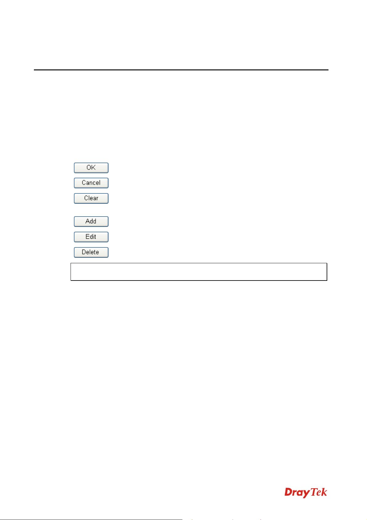
Several main buttons appeared on the web pages are defined as the following:
Save and apply current settings.
Cancel current settings and recover to the previous saved settings.
Clear all the selections and parameters settings, including selection from
drop-down list. All the values must be reset with factory default settings.
Add new settings for specified item.
Edit the settings for the selected item.
Delete the selected item with the corresponding settings.
Note: For the other buttons shown on the web pages, please refer to Chapter 4 for detailed
explanation.
11..22 LLEEDD IInnddiiccaattoorrss aanndd CCoonnnneeccttoorrss
Before you use the Vigor router, please get acquainted with the LED indicators and
connectors first. The displays of LED indicators and connectors for the routers are different
slightly.
Vigor300B Series User’s Guide
1
Page 10
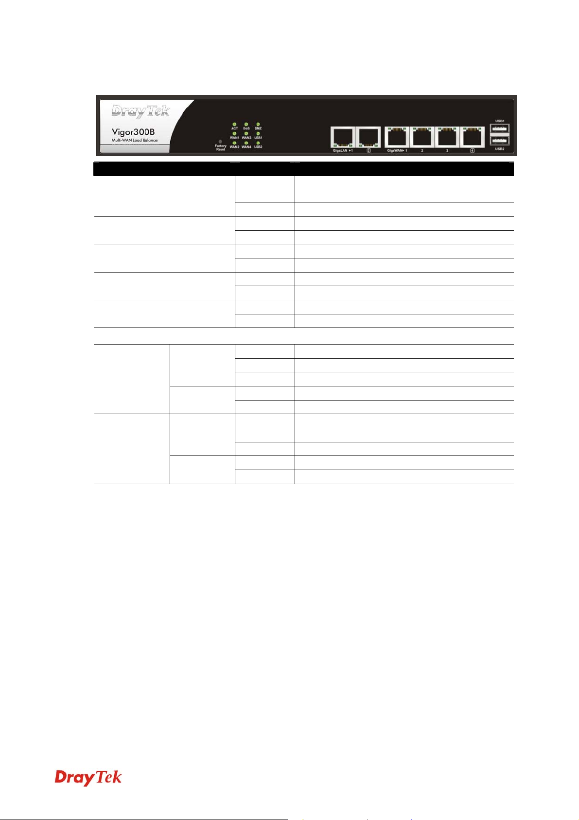
DDeessccrriippttiioonn ffoorr LLEEDD
LED Status Explanation
ACT (Activity)
Blinking The router is powered on and running
normally.
Off The router is powered off.
On The DoS/DDoS function is active. DoS
Blinking It will blink while detecting an attack.
On DMZ Host is specified in certain site. DMZ
Off DMZ Host is inactive.
On The WAN1 or WAN2 connection is ready. WAN1 ~ WAN4
Blinking It will blink while transmitting data.
On USB device is connected and ready for use. USB1 ~ USB2
Blinking The data is transmitting.
LED on Connector
On The port is connected.
Off The port is disconnected.
Blinking The data is transmitting.
On The port is connected with 1000Mbps.
Off The port is disconnected with 10/100Mbps.
On The port is connected.
Off The port is disconnected.
Blinking The data is transmitting.
On The port is connected with 1000Mbps.
Off The port is disconnected with 10/100Mbps.
LAN 1/2
(Giga)
WAN 1/2/3/4
(Giga)
Left LED
(Green)
Right LED
(Green)
Left LED
(Green)
Right LED
(Green)
2
Vigor300B Series User’s Guide
Page 11
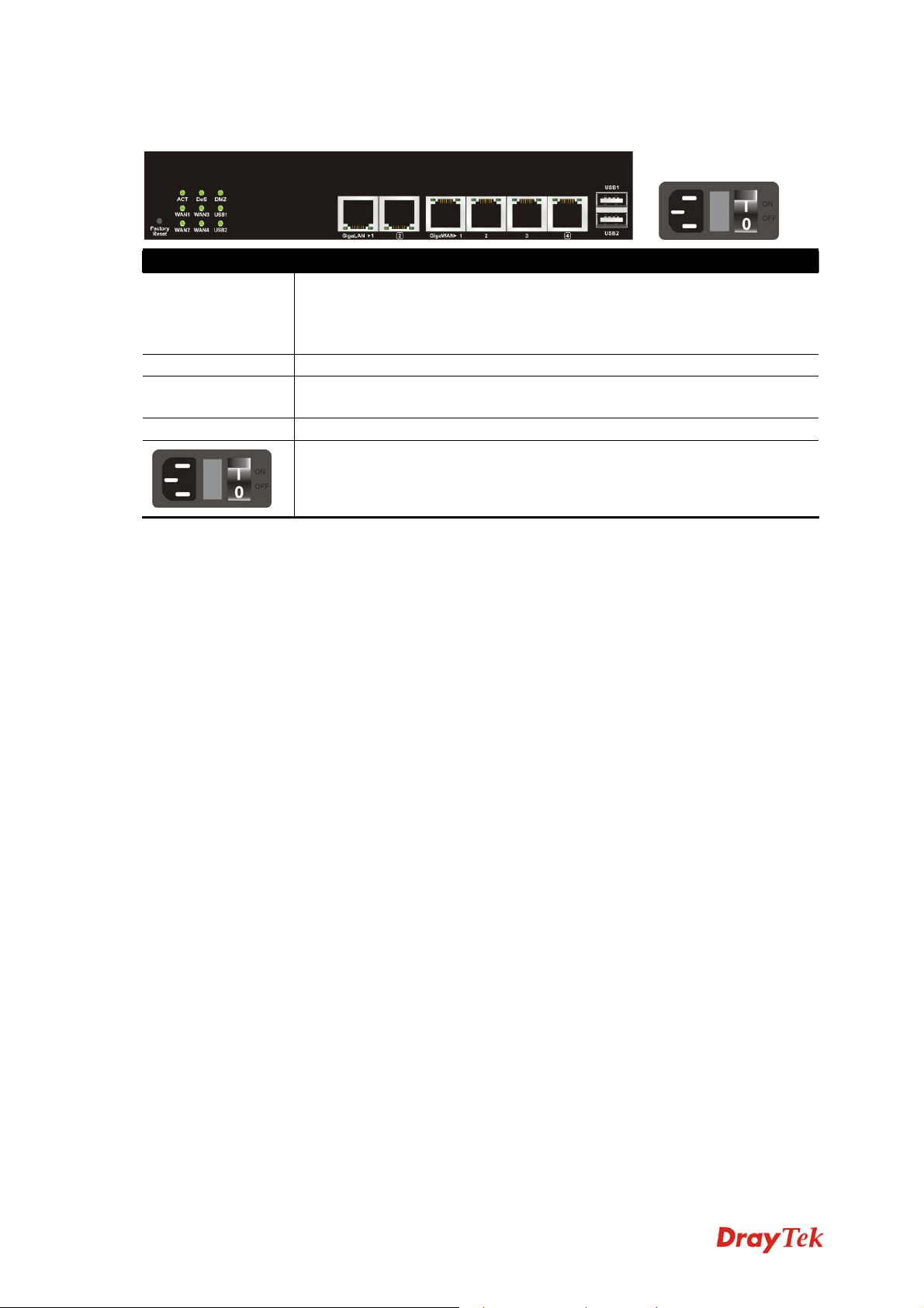
CCoonnnneeccttoorrss
Interface Description
Factory Reset Restore the default settings. Usage: Turn on the router (ACT LED is
blinking). Press the hole and keep for more than 5 seconds. When you
see the ACT LED begins to blink rapidly than usual, release the button.
Then the router will restart with the factory default configuration.
LAN1/2 (Giga) Connecters for local networked devices.
WAN1/2/3/4
Connecters for remote networked devices.
(Giga)
USB1/2 Connecter for Mobile HDD, 3G Modem or printer.
Connecter for a power cord.
ON/OFF - Power switch.
Vigor300B Series User’s Guide
3
Page 12
11..33 HHaarrddwwaarree IInnssttaallllaattiioonn
n
11..33..11 NNeettwwoorrkk CCoonnnneeccttiioon
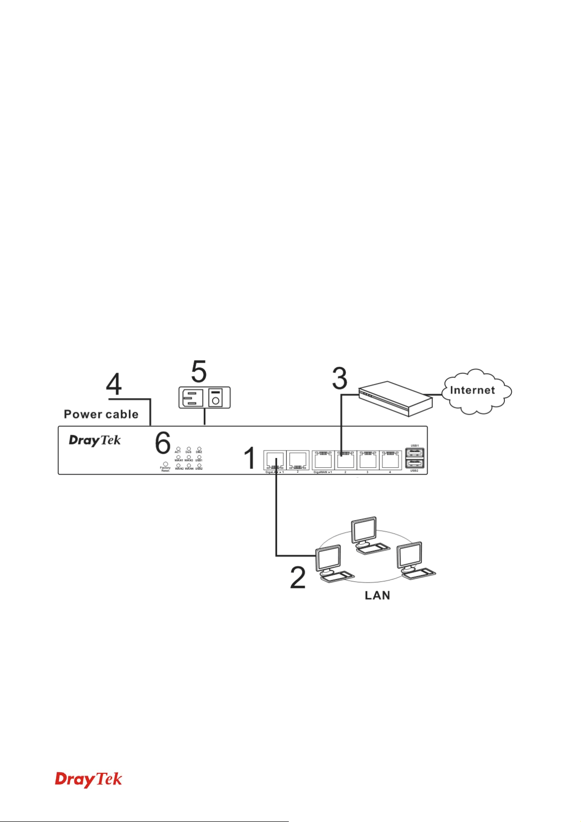
Before starting to configure the router, you have to connect your devices correctly.
1. Connect one end of an Ethernet cable (RJ-45) to one of the LAN ports of Vigor300B.
2. Connect the other end of the cable (RJ-45) to the Ethernet port on your computer (that
device also can connect to other computers to form a small area network). The LAN
LED for that port on the front panel will light up.
3. Connect the cable Modem/DSL Modem/Media Converter to any WAN port of router
with Ethernet cable (RJ-45).
4. Connect the power cord to Vigor300B’s power port on the rear panel, and the other
side into a wall outlet.
5. Power on the device by pressing down the power switch on the rear panel. The PWR
LED should be ON.
6. The system starts to initiate. After completing the system test, the ACT LED will light
up and start blinking.
Below shows an outline of the hardware installation for your reference.
4
Vigor300B Series User’s Guide
Page 13
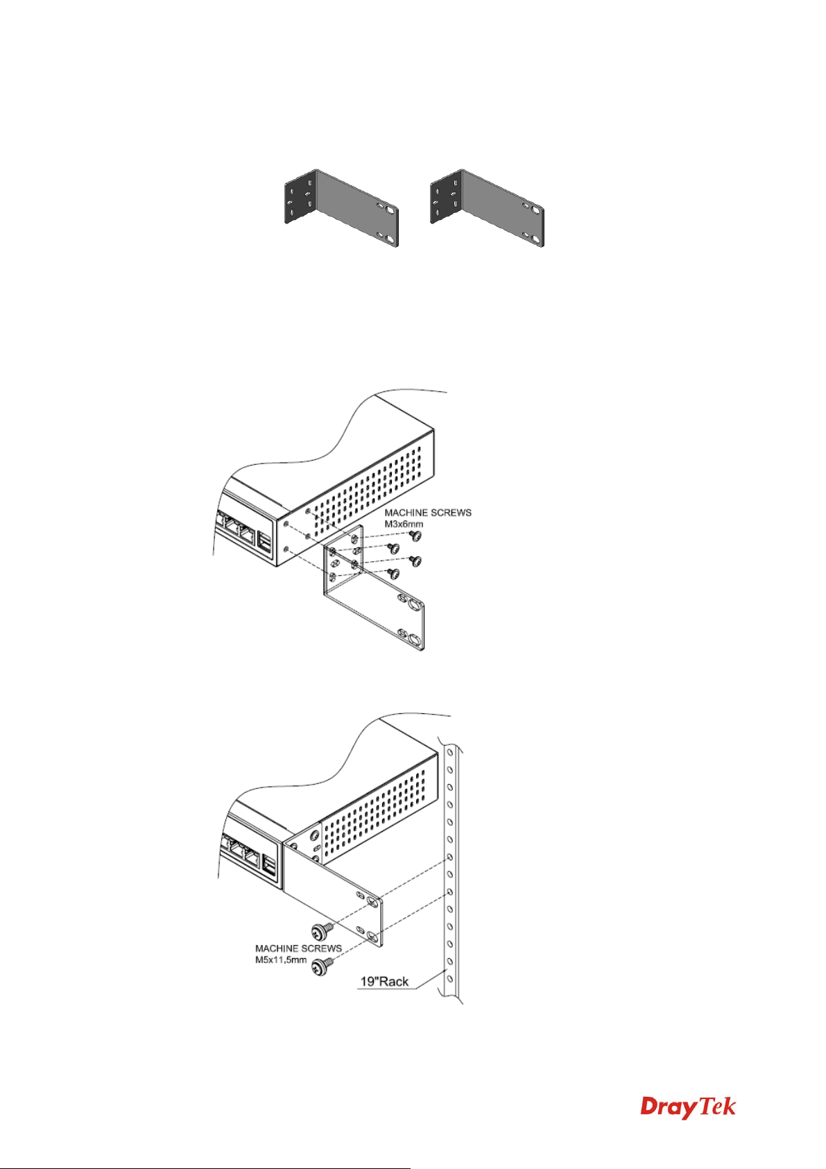
11..33..22 RRaacckk--MMoouunntt aanndd WWaallll--MMoouunntt IInnssttaallllaattiioonn
The Vigor300B can be mounted on the wall by using standard brackets shown below.
Before mounting the router on the wall or the rack, you have to make sure that power is OFF.
Remember to remove the power cable and all network interface cables, and consider the
cable limitations and the wall structure when choosing a wall for mounting.
Do the following steps to mount the router on rack:
1. Attach the brackets on each side of the chassis by using the machine screws. Each side
requires four screws.
2. Make the holes on the brackets align to the holes on the rack. Use machine screws to
fasten the brackets on the rack. Each side requires two screws.
Vigor300B Series User’s Guide
5
Page 14
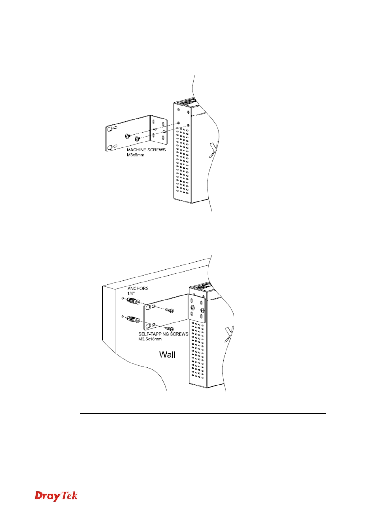
Do the following steps to mount the router on wall:
1. Attach the brackets on each side of the chassis by using the machine screws. Each side
requires two screws.
2. Locate the wall studs for attaching the router. Drill wall-mount screw holes and put the
studs on the holes first.
3. Make the reserved holes on the brackets align to the studs on the wall. Use machine
screws to fasten the brackets on the wall. Each side requires two screws.
Note: Make the front and the rear of the chassis being perpendicular to the floor. The
front panel should be installed upward that you can read the LEDs.
6
Vigor300B Series User’s Guide
Page 15
Chhaapptteerr 22:: IInniittiiaall
C
For use the router properly, it is necessary for you to change the password of web
configuration for security and adjust primary basic settings.
This chapter explains how to setup a password for an administrator and how to adjust basic
settings for accessing Internet successfully. Be aware that only the administrator can change
the router configuration.
22..11 CChhaannggiinngg PPaasssswwoorrdd
To change the password for this device, you have to access into the web browse with default
password first.
1. Make sure your computer connects to the router correctly.
Notice: You may either simply set up your computer to get IP
dynamically from the router or set up the IP address of the computer to be
the same subnet as the default IP address of Vigor router 192.168.1.1.
For the detailed information, please refer to the later section - Trouble
Shooting of this guide.
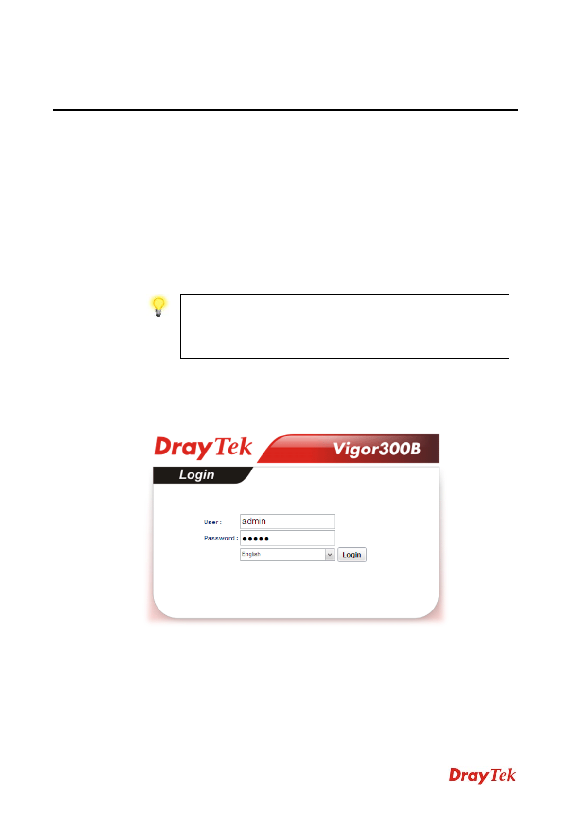
2. Open a web browser on your PC and type http://192.168.1.1. A pop-up window will
open to ask for username and password. Please type default values on the window for
the first time accessing. The default value for user name is admin and the password is
admin. Next, click Login.
Coonnffiigguurraattiioonn
C
Vigor300B Series User’s Guide
7
Page 16
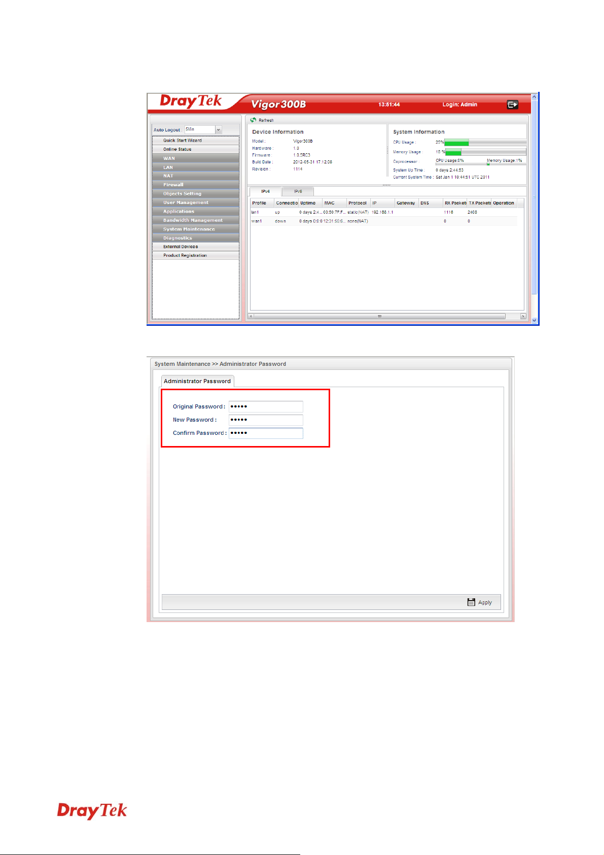
3. Now, the Main Screen will pop up.
4. Go to System Maintenance page and choose Administrator Password.
5. Enter the login password (admin) on the field of Original Password. Type a new one
in the field of New Password and retype it on the field of Confirm Password. Then
click Apply to continue.
6. Now, the password has been changed. Next time, use the new password to access the
Web Configurator for this router.
8
Vigor300B Series User’s Guide
Page 17
22..22 QQuuiicckk SSttaarrtt WWiizzaarrdd
Quick Start Wizard is a wizard which is designed for configuring your router accessing Internet with simply steps. In the Quick Start Wizard group, you can configure the router to access the Internet with different modes such as Static, DHCP, PPPoE, or PPTP modes.
For most users, Internet access is the primary application. The router supports the Ethernet
WAN interface for Internet access.
Click Quick Start Wizard from the home page. Quick Start Wizard will guide the user to
select proper LAN interface profile, WAN interface profile and select proper protocol for
connection. The following will explain in more detail for the various broadband access
configurations.
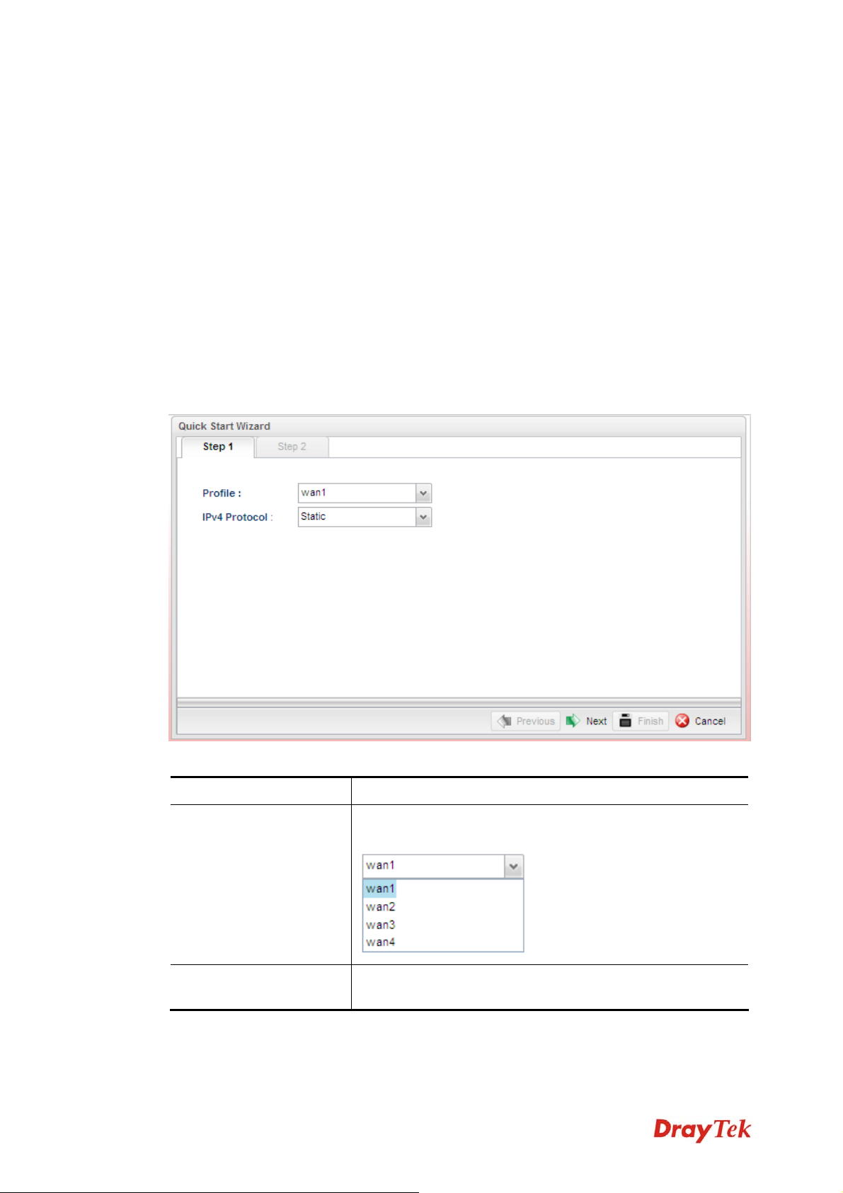
22..22..11 SStteepp 11 -- SSppeecciiffyyiinngg tthhee WWAANN PPrrooffiillee
In the first page of Quick Start Wizard, please choose a WAN profile and specify IPv4
protocol.
Available parameters are listed as follows:
Item Description
Profile
IPv4 Protocol
Vigor300B Series User’s Guide
Use the drop down list to choose one of the WAN profiles
for modifying.
Use the drop down list to choose the type for the IPv4
protocol for such profile.
9
Page 18
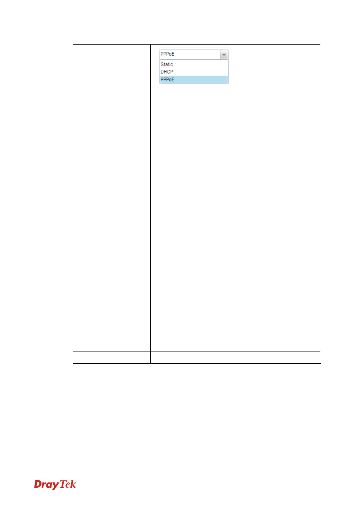
Static - If Static is selected, you can manually assign a static
IP address to the WAN interface and complete the
configuration by applying the settings and rebooting
your router. Please type in values for IP address,
Subnet Mask, Gateway IP Address and DNS
Server IP Address specified by your ISP, and then
click Next.
DHCP - It allows a user to obtain an IP address
automatically from a DHCP server on the Internet. If
you choose DHCP mode, the DHCP server of your
ISP will assign a dynamic IP address for Vigor300B
automatically. It is not necessary for you to assign
any setting. (Host Name and Domain Name are
required for some ISPs).
PPPoE - PPPoE stands for Point-to-Point Protocol over
Ethernet. It relies on two widely accepted
standards: PPP and Ethernet. It connects users
through an Ethernet to the Internet with a common
broadband medium, such as a single DSL line,
wireless device or cable modem. All the users over
the Ethernet can share a common connection.
PPPoE is used for most of DSL modem users. All
local users can share one PPPoE connection for
accessing the Internet. Your service provider will
provide you information about user name, password,
and authentication mode.
If your ISP provides you the PPPoE (Point-to-Point
Protocol over Ethernet) connection, please select
PPPoE for this router to get the following page.
Enter the username and password provided by your
ISP on the web page.
Next
Cancel
Click it to access into the Step 2 page.
Click it to discard all the settings.
When you finish the above settings, please click Next to go to next page.
10
Vigor300B Series User’s Guide
Page 19
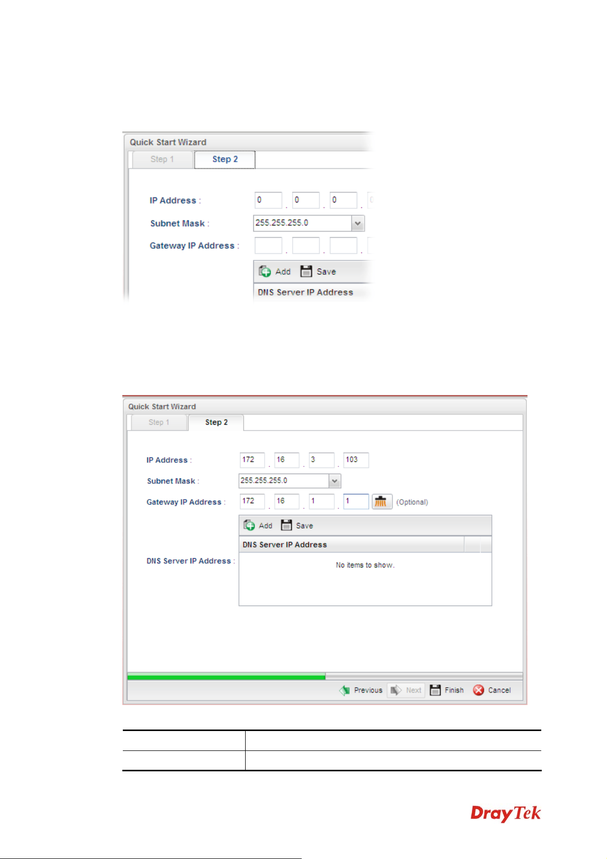
22..22..22 SStteepp 22 -- CCoonnffiigguurriinngg tthhee SSeelleecctteedd PPrroottooccooll
After clicking Next, you can see the following page which will vary according to the IPv4
protocol type selected in Step 1.
IIff SSttaattiicc iiss sseelleecctteedd
If Static is selected, the following screen will appear. You can manually assign a static IP
address to the WAN interface and complete the configuration by applying the settings and
rebooting your router. Please type in values for Static IP address, Static Mask, Static
Gateway and Static DNS specified by your ISP, and then click Next.
Available parameters are listed as follows:
Item Description
IP Address
Vigor300B Series User’s Guide
Type a public IP address for such WAN profile.
11
Page 20
Subnet Mask
Gateway IP Address
DNS Server IP
Address
Choose the static mask from the drop down list.
Type a public gateway address for such WAN profile.
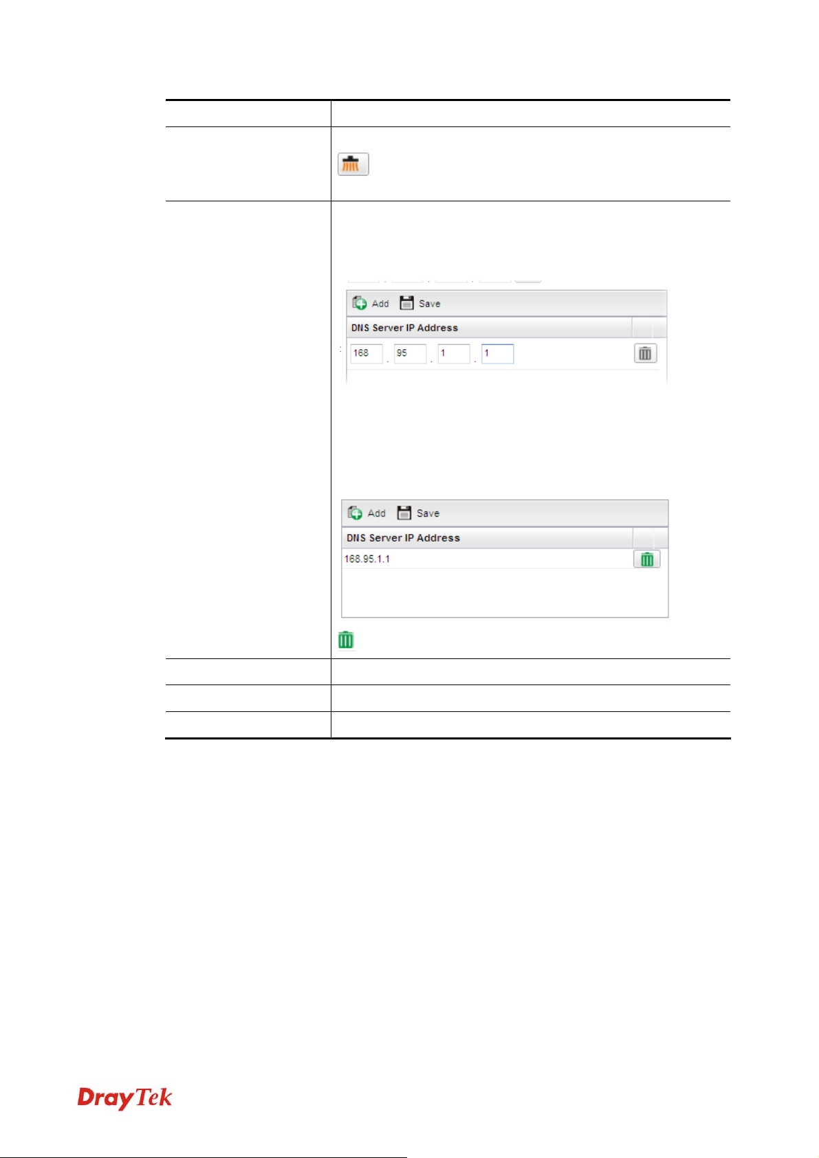
- click it to remove the IP address if you are not satisfied
with it.
Type a public IP address as the primary DNS (Domain Name
Server). To add a new IP address, simply Add. Four boxes will
appear for you to type the IP address. When you finish the
settings, click Save.
Add – Click this button to display the IP address field for
adding a new IP address. Type the IP address on the tiny boxes
one by one.
Save – After finished the IP address configuration, click it to
save the setting onto the router.
– Click the icon to remove the selected entry.
Previous
Finish
Cancel
Click it to return to previous setting page.
Click it to finish the configuration.
Click it to exit the wizard without saving the configuration.
When you finished the above settings, please click Finish.
12
Vigor300B Series User’s Guide
Page 21
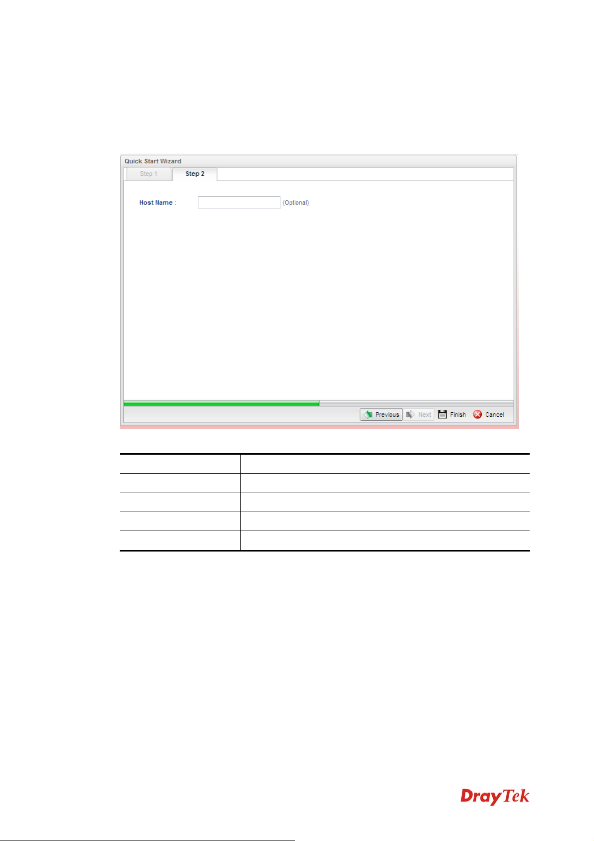
IIff DDHHCCPP iiss sseelleecctteedd
DHCP allows a user to obtain an IP address automatically from a DHCP server on the
Internet. If you choose DHCP mode, the DHCP server of your ISP will assign a dynamic IP
address for Vigor300B automatically. It is not necessary for you to assign any setting. (Host
Name is required for some ISPs).
Available parameters are listed as follows:
Item Description
Host Name (Optional)
Previous
Finish
Cancel
Type a name as the host name for identification.
Click it to return to previous setting page.
Click it to finish the configuration.
Click it to exit the wizard without saving the configuration.
When you finished the above settings, please click Finish.
Vigor300B Series User’s Guide
13
Page 22
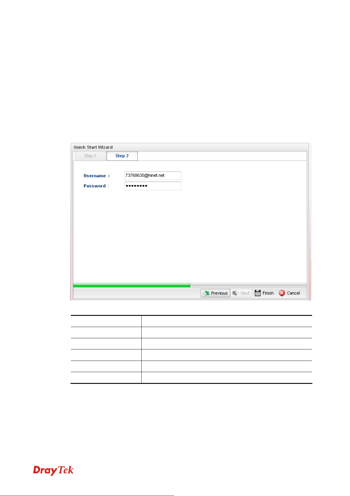
IIff PPPPPPooEE iiss sseelleecctteedd
PPPoE stands for Point-to-Point Protocol over Ethernet. It relies on two widely accepted
standards: PPP and Ethernet. It connects users through an Ethernet to the Internet with a
common broadband medium, such as a single DSL line, wireless device or cable modem. All
the users over the Ethernet can share a common connection.
PPPoE is used for most of DSL modem users. All local users can share one PPPoE
connection for accessing the Internet. Your service provider will provide you information
about user name, password, and authentication mode.
If your ISP provides you the PPPoE (Point-to-Point Protocol over Ethernet) connection,
please select PPPoE for this router to get the following page. Enter the username and
password provided by your ISP on the web page.
Available parameters are listed as follows:
Item Description
Username
Password
Previous
Finish
Cancel
Type in the username provided by ISP in this field.
Type in the password provided by ISP in this field.
Click it to return to previous setting page.
Click it to finish the configuration.
Click it to exit the wizard without saving the configuration.
14
Vigor300B Series User’s Guide
Page 23
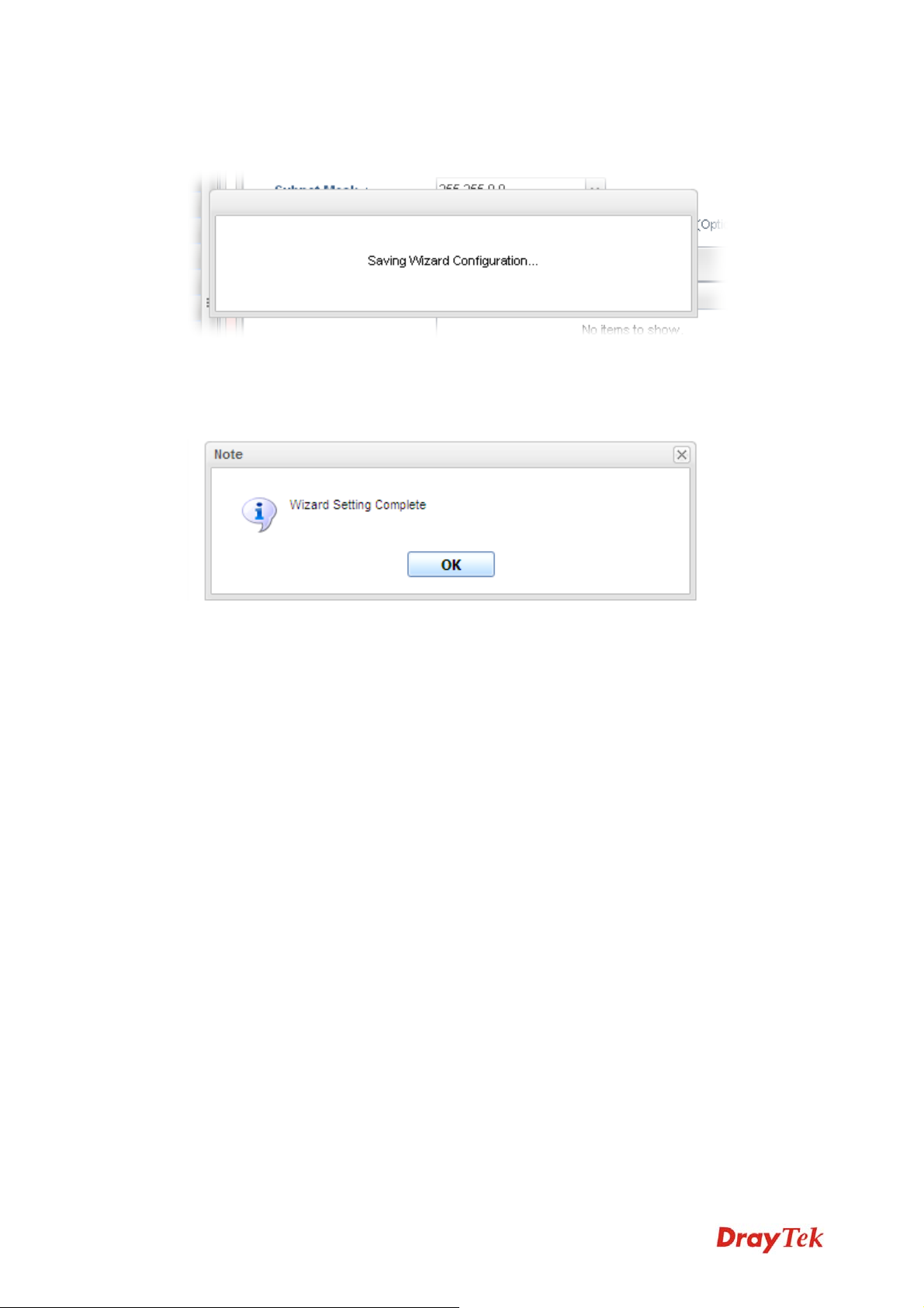
When you finished the above settings, please click Finish. Later, you can surf the Internet at
any time.
When the following screen appears, it means you have finished the Quick Start Wizard
configuration.
Vigor300B Series User’s Guide
15
Page 24
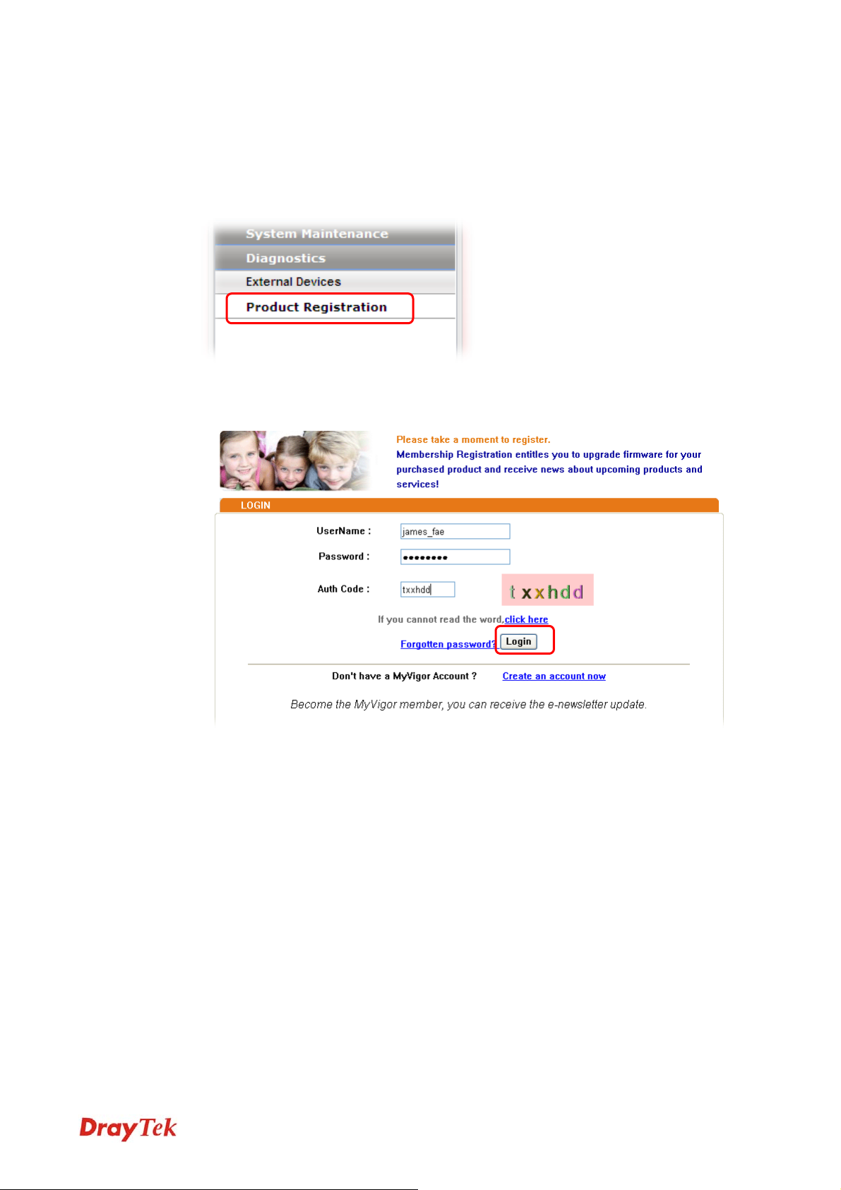
22..33 RReeggiisstteerr VViiggoorr RRoouutteerr
Please follow the steps below to register the router.
1 Before using such function, please register your router online first. Log into the web
configurator of Vigor300B and click Product Registration.
2 A Login page will be shown on the screen. Please type the account and password that
you created previously. And click Login.
16
Vigor300B Series User’s Guide
Page 25
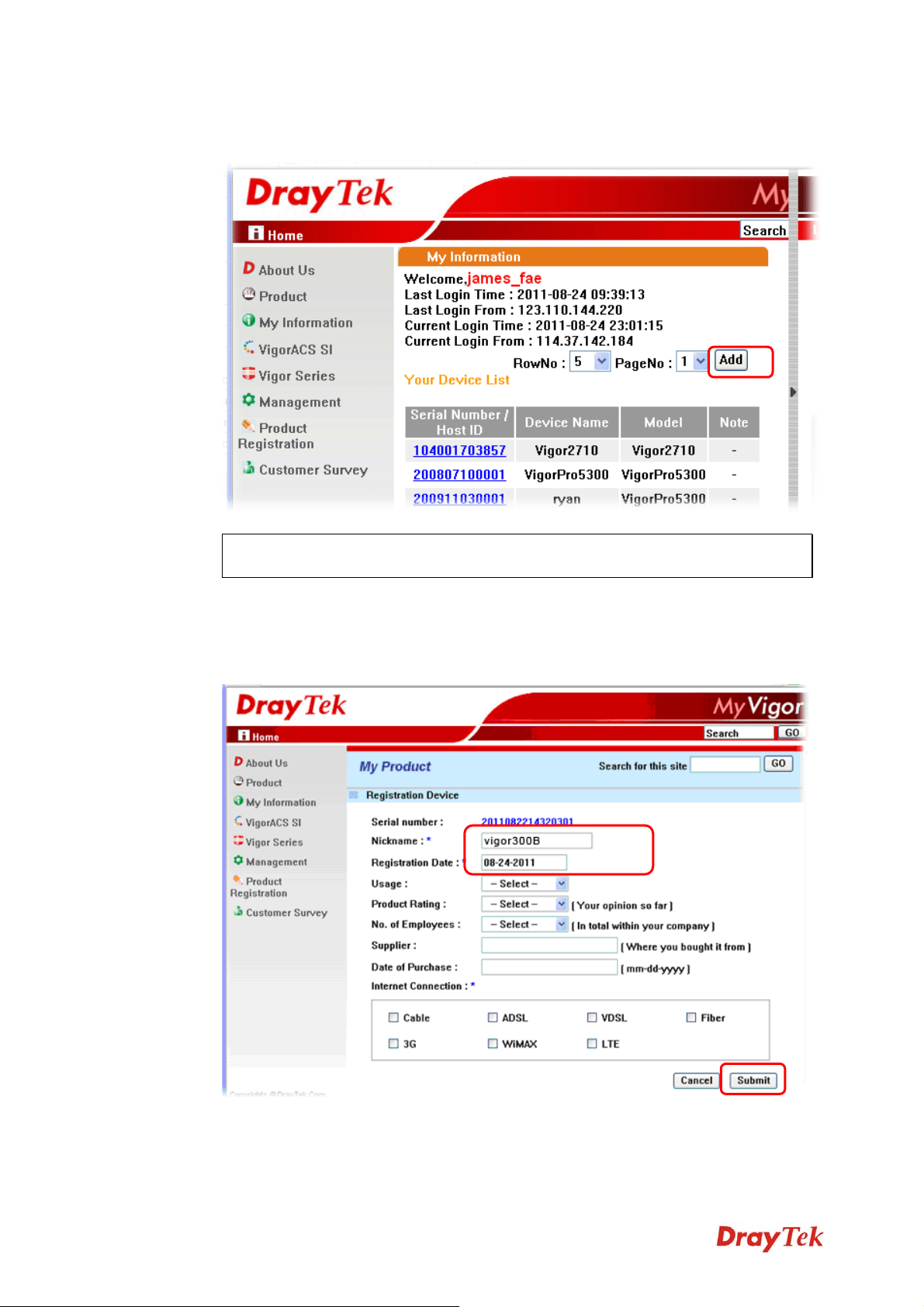
3 The following page will be displayed after you logging in MyVigor. From this page,
please click Add.
Note: Below the field of Your Device List, all the Vigor routers that you have
registered to MyVigor website will be displayed in sequence.
4 When the following page appears, please type in Nick Name (for the router) and choose
the right registration date from the popup calendar (it appears when you click on the
box of Registration Date). After adding the basic information for the router, please click
Submit.
Vigor300B Series User’s Guide
17
Page 26
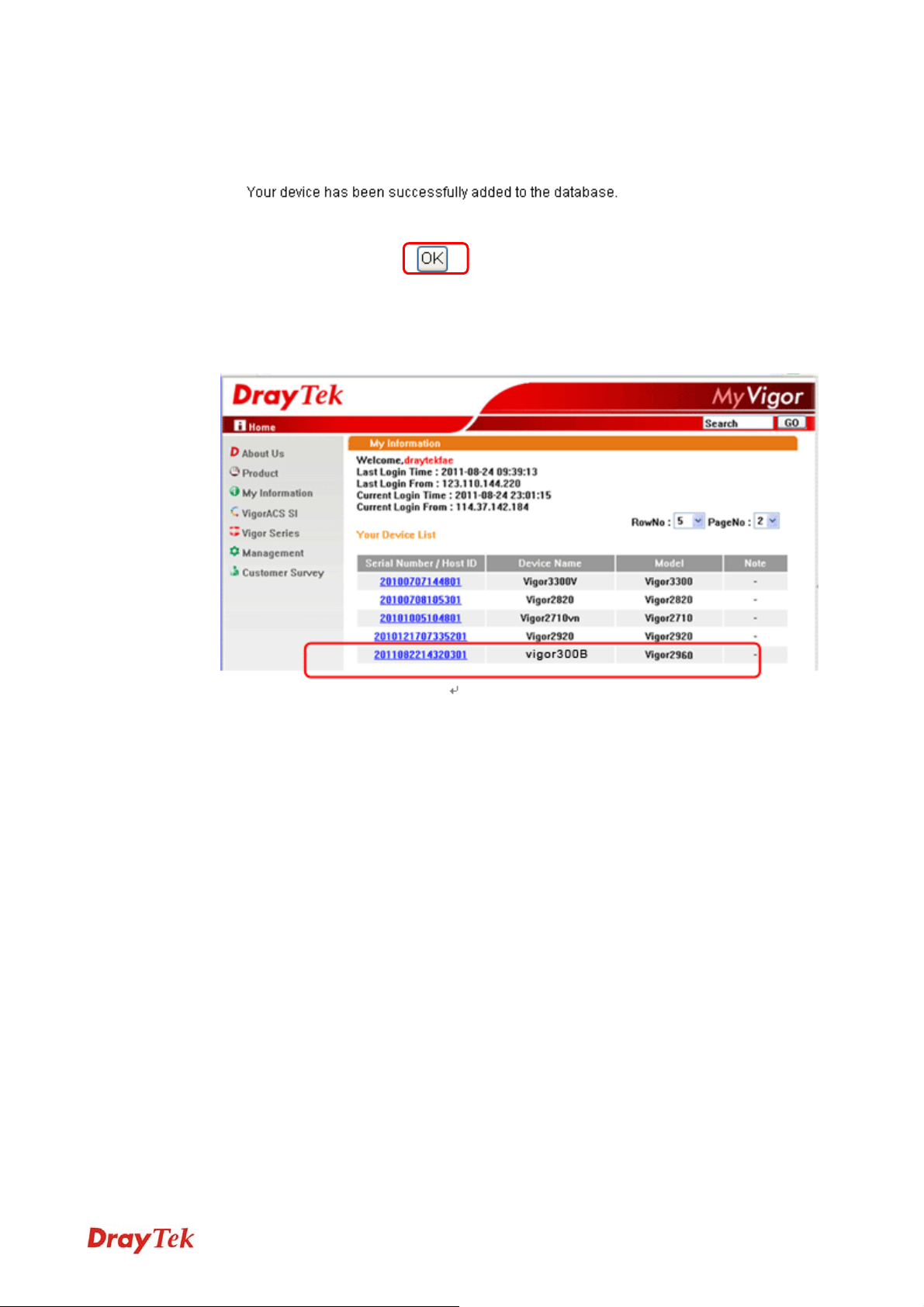
5 Now, your router information has been added to the database. Click OK to leave this
web page and return to My Information web page.
6 Take a look at the page of My Information, the new added Vigor300B is listed under
Your Device List.
18
Vigor300B Series User’s Guide
Page 27
Chhaapptteerr 33::
C
Tuuttoorriiaall
T
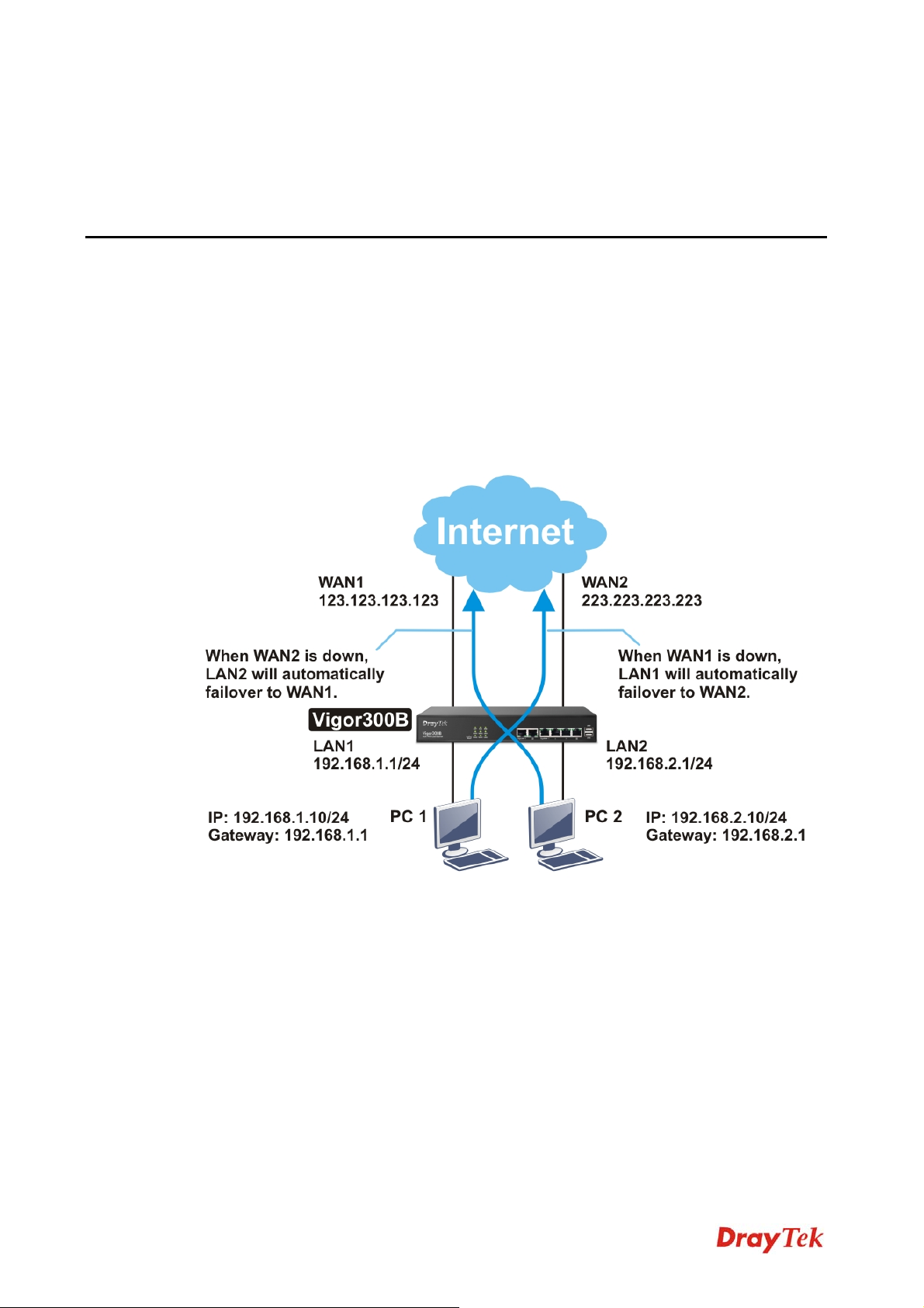
33..11 HHooww ttoo CCoonnffiigguurree LLooaadd BBaallaannccee wwiitthh MMuullttii--WWAANN oon
VViiggoorr330000BB??
There are two different LANs configured in the following figure. One is for Sale
(192.168.1.1/24) and the other is for FAE(192.168.2.1/24). Sale's LAN will be configured to
go Internet always via WAN1. When WAN1 is down, Sale's LAN will automatically failover
to WAN2. FAE's LAN will be configured to go Internet always via WAN2, but when WAN2
is down Sale's LAN will automatically failover to WAN1.
Apppplliiccaattiioonn aanndd
A
n
Vigor300B Series User’s Guide
19
Page 28
1. Access into the web configurator page of Vigor300B.
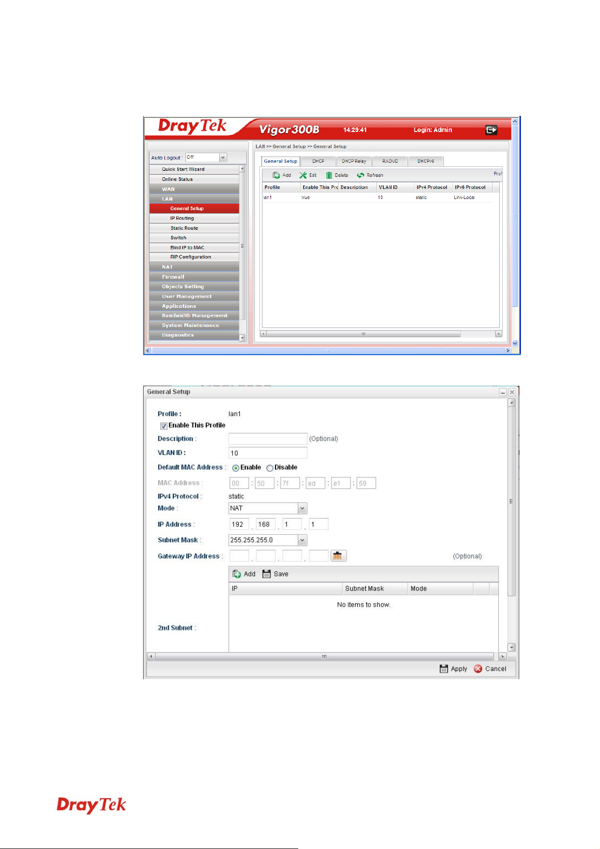
2. Go to LAN>>General Setup to create a profile for LAN1 (192.168.1.1/24).
3. Click Add to open the following page.
Type the information specified for LAN1 profile, then click Apply to save the settings
and exit the screen.
20
Vigor300B Series User’s Guide
Page 29

4. Click Add again to create a profile for LAN2 (192.168.2.1/24).
Type the information specified for LAN2 profile, then click Apply to save the settings
and exit the screen.
5. Open WAN >> Load Balance and click the Pool tab.
Vigor300B Series User’s Guide
21
Page 30
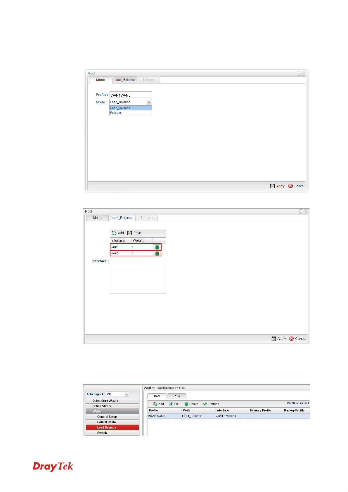
6. Click Add under the Pool tab to create a profile (e.g., WAN1WAN2) for automatic
Load Balance between WAN1 and WAN2. Choose Load_Balance as the Mode
option.
7. Click the Load_Balance tab to open the following page.
Setup the Weights (e.g, “1”) of WAN1 and WAN2 as you want. In this case ratio of
WAN1 and WAN2 is 1:1. Also, you can type 2 and 1 for WAN1 and WAN2, then the
ratio of line speed of WAN 1and line speed of WAN 2 will be 2:1.
8. After clicking Apply, the created profile will be shown on the screen.
22
Vigor300B Series User’s Guide
Page 31

9. Open WAN >> Load-Balance and click the Rule tab.
10. Click Add to create a profile for Rule1 accepting the data coming from 192.168.1.0/24
which always goes Internet via WAN1 when WAN1 is up. Type the information
specified for such rule. (e.g., Rule1 for Profile; 192.168.1.0 for Source IP Address;
wan1 for Load Balance Pool/WAN Profile and so on). Next, click Apply to save and
exit.
Vigor300B Series User’s Guide
23
Page 32

11. Click Add again to create a profile for Rule2 accepting 192.168.2.0/24 which always
goes Internet via WAN2 when WAN2 is up.
12. After clicking Apply, the created profiles will be shown on the screen.
13. Next, open WAN >> Default Route. Choose the profile of “WAN1WAN2” as WAN
Profile/Loadbalance Pool Name.
Note: The priority of WAN >> Load Balance>>Rule is higher than WAN >>
Default Route.
Now, you have completed the configuration. Next time, when WAN1 is down, the
connection for PCs behind Sale's LAN (192.168.1.1/24) will automatically failover to
WAN2.
24
Vigor300B Series User’s Guide
Page 33

Chhaapptteerr 44::
C
Coonnffiigguurraattiioonn
C
After finished basic configuration of the router, you can access Internet with ease. For the
people who want to adjust more setting for suiting his/her request, please refer to this chapter
for getting detailed information about the advanced configuration of this router. As for other
examples of application, please refer to chapter 3.
44..11 WWAANN SSeettuupp
Quick Start Wizard offers user an easy method to quick setup the connection mode for the
router. Moreover, if you want to adjust more settings for different WAN modes, please go to
WAN group and click the General Setup link.
BBaassiiccss ooff IInntteerrnneett PPrroottooccooll ((IIPP)) NNeettwwoorrkk
IP means Internet Protocol. Every device in an IP-based Network including routers, print
server, and host PCs, needs an IP address to identify its location on the network. To avoid
address conflicts, IP addresses are publicly registered with the Network Information Centre
(NIC). Having a unique IP address is mandatory for those devices participated in the public
network but not in the private TCP/IP local area networks (LANs), such as host PCs under
the management of a router since they do not need to be accessed by the public. Hence, the
NIC has reserved certain addresses that will never be registered publicly. These are known as
private IP addresses, and are listed in the following ranges:
Addvvaanncceedd
A
From 10.0.0.0 to 10.255.255.255
From 172.16.0.0 to 172.31.255.255
From 192.168.0.0 to 192.168.255.255
WWhhaatt aarree PPuubblliicc IIPP AAddddrreessss aanndd PPrriivvaattee IIPP AAddddrreessss
As the router plays a role to manage and further protect its LAN, it interconnects groups of
host PCs. Each of them has a private IP address assigned by the built-in DHCP server of the
Vigor router. The router itself will also use the default private IP address: 192.168.1.1 to
communicate with the local hosts. Meanwhile, Vigor router will communicate with other
network devices through a public IP address. When the data flow passing through, the
Network Address Translation (NAT) function of the router will dedicate to translate
public/private addresses, and the packets will be delivered to the correct host PC in the local
area network. Thus, all the host PCs can share a common Internet connection.
GGeett YYoouurr PPuubblliicc IIPP AAddddrreessss ffrroomm IISSPP
In ADSL deployment, the PPP (Point to Point)-style authentication and authorization is
required for bridging customer premises equipment (CPE). Point to Point Protocol over
Ethernet (PPPoE) connects a network of hosts via an access device to a remote access
concentrator or aggregation concentrator. This implementation provides users with
significant ease of use. Meanwhile it provides access control, billing, and type of service
according to user requirement.
When a router begins to connect to your ISP, a serial of discovery process will occur to ask
for a connection. Then a session will be created. Your user ID and password is authenticated
Vigor300B Series User’s Guide
25
Page 34

via PAP or CHAP with RADIUS authentication system. And your IP address, DNS server,
and other related information will usually be assigned by your ISP.
44..11..11 GGeenneerraall SSeettuupp
This section will introduce some general settings of Internet and explain the connection
modes for WAN profiles in details.
This router supports multi-WAN function. It allows users to access Internet and combine the
bandwidth of the WAN profiles to speed up the transmission through the network. Each
WAN port can connect to different ISPs, even if the ISPs use different technology to provide
telecommunication service (such as DSL, Cable modem, etc.). If any connection problem
occurred on one of the ISP connections, all the traffic will be guided and switched to the
normal communication port for proper operation.
Each item will be explained as follows:
Item Description
Edit
Modify the selected WAN profile.
To edit a profile, simply select the one you want to modify
and click the Edit button. The edit window will appear for
you to modify the corresponding settings for the selected
rule.
Refresh
Profile
Renew current web page.
Display the profile name.
26
Vigor300B Series User’s Guide
Page 35

Enable This Profile
Display the status of the profile. False means disabled; True
means enabled.
Description
VLAN ID
VLAN Tag
Display a brief explanation for such profile.
Display the VLAN ID of the profile.
If the data transmitted with tag, Enable will be displayed in
this field. Otherwise, Disable will be shown instead.
Port
IPv4 Protocol Type
IPv6 Protocol Type
HHooww ttoo eeddiitt tthhee WWAANN pprrooffiillee
Display the physical WAN interface for such profile.
Display the IPv4 protocol selected by the profile.
Display the IPv6 protocol selected by the profile.
1. Open WAN>>General Setup. Choose wan1/wan2/wan3/wan4 profile and click the
Edit button to open the following dialog. Only the tab of the protocol specified in IPv4
Protocol field will be available for you to modify. If you want to change and specify
another connection mode for such WAN profile, remember to choose the mode from
the drop down list of IPv4 Protocol.
Available parameters for global configuration are listed as follows:
Item Description
Profile
Enable This Profile
Description
VLAN ID
VLAN Tag
Vigor300B Series User’s Guide
Type a name for such profile.
Check this box to enable such profile.
Give the brief description for such profile.
Type the VLAN ID number for such profile.
Enable – Click it to enable the function of VLAN Tag. Data
27
Page 36

transmitted through the router will not be tagged with any
number.
Disable – Click it to disable the function of VLAN Tag.
Data transmitted through the router will be tagged with
specified number for identification.
Port
Default MAC
Address
Mode
IPv4 Protocol
Display the physical WAN interface for such profile.
Enable – Click it to enable the default MAC address for
such profile.
Disable – Click it to type the MAC address manually for
such profile.
MAC Address - Specify the MAC address for such profile if
you click Disable for Default MAC address. In default, the
system will determine it automatically.
Determine such profile will be used for NAT or routing.
There are four connection modes for you to specify for IPv4
protocol type. Each mode will bring up different web page.
IPv6 Protocol
There are four connection modes for you to specify for IPv6
protocol type. Each mode will bring up different web page.
Global configuration allows you to enable the profile, give a brief explanation for such
profile, specify the VLAN ID, specify MAC address, choose IPv4 and IPv6 protocol,
and specify the mode of the data transmission (NAT or Routing).
28
Vigor300B Series User’s Guide
Page 37

Different IPv4 and IPv6 protocol types specified will bring up different configuration
web page.
z If you choose Static as IPv4 protocol type, click the Static tab to open the following
page:
Available parameters are listed as follows:
Item Description
IP Address
Subnet Mask
Type the IP address specified for such profile.
Use the drop down list to choose the subnet mask for such
profile.
Gateway IP
Type a public gateway address for such WAN profile.
Address
- click it to remove the IP address if you are not
satisfied with it.
DNS Server IP
Address
Add – Click this button to display the IP address field for
adding a new IP address. Type the IP address on the tiny
boxes one by one.
Save – After finished the IP address configuration, click
Save to save the setting onto the router.
Vigor300B Series User’s Guide
29
Page 38

– Click the icon to remove the selected entry.
IP Alias
Type other IP addresses to be bound to this interface. This
setting is optional. If you have typed addresses here, you can
see and choose it in later web page settings (e.g.,
NAT>>Port Redirection/DMZ Host).
Add – Click this button to display the IP address field for
adding a new IP address. Type the IP address on the tiny
boxes one by one.
Save – After finished the IP address configuration, click
Save to save the setting onto the router.
– Click the icon to remove the selected entry.
MTU/MRU
Connection
Detection Mode
Connection
Detection Host
Type the value of MTU/MRU. The default value is 1500.
Select a detecting mode for this WAN interface. There are
three ways ARP, PING and HTTP supported in Vigor
router for you to choose to send the request out.
Add – Click this button to have a field for adding a new IP
address. Assign an IP address or Domain name as a
destination to be detected whether the host is active (sending
reply to the router) or not. If not, the connection of WAN
interface will be regarded as breaking down. This function
is available when Connection Detection Mode is set with
PING or HTTP.
30
Vigor300B Series User’s Guide
Page 39

Save – click this button to save the setting.
– click the icon to remove the selected entry.
Connection
Assign an interval period of time for each detecting.
Detection Interval
Connection
Detection Retry
Assign detecting times to ensure the connection of the WAN
interface. After passing the times you set in this field and no
reply received by the router, the connection of WAN
interface will be regarded as breaking down.
Apply
Cancel
Click it to save the configuration and exit the dialog.
Click it to exit the dialog without saving the configuration.
z If you choose DHCP as IPv4 protocol type, click the DHCP Tab to open the
following page:
Available parameters are listed as follows:
Item Description
Host Name
(Optional)
Vigor300B Series User’s Guide
Type a name as the host name for identification.
31
Page 40

IP Alias
MTU/MRU
Connection
Detection Mode
Type other IP addresses to be bound to this interface. This
setting is optional. If you have typed addresses here, you can
see and choose it in later web page settings (e.g.,
NAT>>Port Redirection/DMZ Host).
Add – To add a new IP address, click Add. Type the IP
address and use the drop down list to specify the subnet
mask. Next, click Save. The new one will be added and
displayed on the field under the box.
Save – Click this button to save the setting.
– Click the icon to remove the selected entry.
It means Max Transmit Unit for packet. The default setting
is 1500.
Select a detecting mode for this WAN interface. There are
three ways ARP, PING and HTTP supported in Vigor
router for you to choose to send the request out.
Connection
Detection Host
Connection
Detection Interval
Connection
Detection Retry
Add – click this button to have a field for adding a new IP
address. Assign an IP address or Domain name as a
destination to be detected whether the host is active (sending
reply to the router) or not. If not, the connection of WAN
interface will be regarded as breaking down. This function is
available when Connection Detection Mode is set with
PING or HTTP.
Save – Click this button to save the setting.
– Click the icon to remove the selected entry.
Assign an interval period of time for each detecting.
Assign detecting times to ensure the connection of the WAN
interface. After passing the times you set in this field and no
reply received by the router, the connection of WAN
32
Vigor300B Series User’s Guide
Page 41

interface will be regarded as breaking down.
Apply
Cancel
Click it to save the configuration and exit the dialog.
Click it to exit the dialog without saving the configuration.
z If you choose PPPoE as IPv4 protocol type, click the PPPoE Tab to open the
following page:
Available parameters are listed as follows:
Item Description
Username
Password
MTU/MRU
Debug
Type the user name offered by your ISP.
Type the password offered by your ISP.
Type the value of MTU/MRU. The default value is 1492.
Click Enable to display the PPPoE debug message in
Syslog. The default setting is Disable.
Always On
Enable – Click it to enable the function of Always On. The
router will keep network connection all the time.
Disable – Click it to disable the function of Always On.
Fixed IP
Enable – Click it to enable the function of Always On. The
router will keep network connection all the time.
Disable – Click it to disable the function of Always On.
Fixed IP Address – Type an IP address here if you choose
Enable for Fixed IP.
Connection
Detection Mode
Select a detecting mode for this WAN interface. There are
two ways PING and HTTP supported in Vigor router for
you to choose to send the request out.
Vigor300B Series User’s Guide
33
Page 42

Connection
Detection Host
If you choose PING/HTTP as Connection Detection Mode,
you have to specify the detection host address in this field.
Use the default setting.
Add – Click this button to have a field for adding a new IP
address. Assign an IP address or Domain name as a
destination to be detected whether the host is active (sending
reply to the router) or not. If not, the connection of WAN
interface will be regarded as breaking down. This function
is available when Connection Detection Mode is set with
PING or HTTP.
Connection
Detection Interval
Connection
Detection Retry
IP Alias
Save – Click this button to save the setting.
– Click the icon to remove the selected entry.
Assign an interval period of time for each detecting.
Assign detecting times to ensure the connection of the WAN
interface. After passing the times you set in this field and no
reply received by the router, the connection of WAN
interface will be regarded as breaking down.
Type other IP addresses to be bound to this interface. This
setting is optional. If you have typed addresses here, you can
see and choose it in later web page settings (e.g.,
NAT>>Port Redirection/DMZ Host).
Add – Click this button to display the IP address field for
adding a new IP address. Type the IP address on the tiny
boxes one by one.
Save – After finished the IP address configuration, click
Save to save the setting onto the router.
34
Vigor300B Series User’s Guide
Page 43

– Click the icon to remove the selected entry.
Apply
Cancel
Click it to save the configuration and exit the dialog.
Click it to exit the dialog without saving the configuration.
z If you choose DMZ (only available in wan4 profile) as IPv4 protocol type, click the
DMZ Tab to open the following page:
Available parameters are listed as follows if you choose NAT as DMZ Mode:
Item Description
DMZ Mode
IP Address
Subnet Mask
Apply
Vigor300B Series User’s Guide
Choose NAT or Routing as DMZ mode.
Type the IP address specified for such profile.
Use the drop down list to choose the subnet mask for such
profile.
Click it to save the configuration and exit the dialog.
35
Page 44

Cancel
Click it to exit the dialog without saving the configuration.
Available parameters are listed as follows if you choose Routing as DMZ Mode:
Item Description
DMZ Mode
Choose NAT or Routing as DMZ mode.
DMZ Outgoing
Choose any on the WAN interfaces for DMZ outgoing.
Interface
DMZ Host IP List
Apply
Cancel
Enter the private IP address of the DMZ host.
Click it to save the configuration and exit the dialog.
Click it to exit the dialog without saving the configuration.
z If you choose Link-Local as IPv6 protocol type
Link-Local address is used for communicating with neighbouring nodes on the same
link. It is defined by the address prefix fe80::/64. You don't need to setup Link-Local
address manually for it is generated automatically according to your MAC Address.
36
Vigor300B Series User’s Guide
Page 45

z If you choose Static as IPv6 protocol type, click the StaticV6 tab to open the
following page:
Available parameters are listed as follows:
Item Description
IPv6 Address
IPv6 Prefix Length
IPv6 Gateway
Type the IP address for such protocol.
Type your IPv6 address prefix length.
Type your IPv6 gateway address.
Address
IPv6 DNS Server
Type your IPv6 primary DNS Server address.
Address
Add – Click this button to have a field for adding a new IP
address.
Apply
Cancel
Vigor300B Series User’s Guide
Save – Click this button to save the setting.
– Click the icon to remove the selected entry.
Click it to save the configuration and exit the dialog.
Click it to exit the dialog without saving the configuration.
37
Page 46

z If you choose DHCP-IA_NA as IPv6 protocol type, click the DHCPV6 Tab to open
the following page:
Available parameters are listed as follows:
Item Description
DHCP (IA_NA)
Type the gateway IP address for IPv6 DHCP IA_NA mode.
Gateway Address
DHCP (IA_NA)
DNS Address
Add – Click this button to type primary DNS server address
for IPv6.
Save – Click this button to save the setting.
– Click the icon to remove the selected entry.
Apply
Cancel
Click it to save the configuration and exit the dialog.
Click it to exit the dialog without saving the configuration.
38
Vigor300B Series User’s Guide
Page 47

z If you choose DHCP-IA_PD as IPv6 protocol type
It is not necessary for you to configure any web page.
2. After finished the settings configuration, click Apply to save and apply the settings.
44..11..22 DDeeffaauulltt RRoouuttee
This page allows you to assign a WAN profile as the default route.
Available parameters are listed as follows:
Item Description
WAN Profile
/Loadbalance Pool
Display the WAN or load balance profiles for the user to
choose as a default route.
Name
Refresh
Apply
Renew the page configuration.
Click it to save the configuration.
Vigor300B Series User’s Guide
39
Page 48

44..11..33 LLooaadd BBaallaannccee
Vigor300B supports a load balancing function. It can assign traffic with protocol type, IP
address for specific host, a subnet of hosts, and port range to be allocated in WAN interface.
User can assign traffic category and force it to go to dedicate network interface based on the
following web page setup.
In the WAN group, click the Load Balance option.
PPooooll
This page allows the user to integrate several WAN profiles as a pool profile specified with
the function of load balance or failover. The profiles configured here will be selected in the
field of WAN>>Default Route page.
Each item will be explained as follows:
Item Description
Add
Edit
Add a new pool profile.
Modify the selected pool profile.
To edit a profile, simply select the one you want to modify
and click the Edit button. The edit window will appear for
you to modify the corresponding settings for the selected
pool.
Delete
Remove the selected pool profile.
To delete a rule, simply select the one you want to delete and
click the Delete button.
Refresh
Profile
Mode
Renew current web page.
Display the name of the rule.
Display the protocol of such rule.
40
Vigor300B Series User’s Guide
Page 49

Interface
Display the name of the WAN profiles for Load Balance
rule.
Primary Profile
Display the primary profile configured in Failover page for
such profile.
Backup Profile
Display the backup profile configured in Failover page for
such profile.
There are two modes, Load_Balance and Failover, for you to choose as the Pool
configuration. If you choose Load_Balance, the tab of Load_Balance will be shown which
allows you to configure for different WAN interfaces. If you choose Failover, the tab of
Failover will be displayed which allows you to specify the primary profile and backup
profile for such Pool setting.
HHooww ttoo aadddd aa ppooooll pprrooffiillee ffoorr LLooaadd BBaallaannccee
1. Open WAN>>Load Balance and click the tab of Pool.
2. Simply click the Add button to open the following dialog. Type a name for such profile
(e.g., LB_1). Choose Load_Balance as the Mode selection.
Vigor300B Series User’s Guide
41
Page 50

3. Click the Load_Balance Tab.
4. Click Add. A new line for adding new entry will appear. Use the drop down list of
Interface to choose one of the WAN profiles. Type the value (e.g., 20) for Weight.
5. Click Apply. A new profile will be added on the page.
42
Vigor300B Series User’s Guide
Page 51

HHooww ttoo aadddd aa PPooooll pprrooffiillee ffoorr FFaaiilloovveerr
Such page allows you to set a backup profile which will be activated when the primary
profile is invalid by any reason.
1. Open WAN>>Load Balance and click the tab of Pool.
2. Simply click the Add button to open the following dialog. Type a name for such profile
(e.g., FL_1). Choose Failover as the Mode selection.
Vigor300B Series User’s Guide
43
Page 52

3. Click the Failover Tab. In default, the system will apply Primary Profile. If Primary
Profile cannot be used any more, the Backup Profile will be used instead.
4. Use the drop down list to choose the one you need.
5. Click Apply. A new profile will be added on the page.
44
Vigor300B Series User’s Guide
Page 53

RRuullee
This page will make the packets be transmitted with user defined profiles with IP address
and protocol that is different with default route.
Each item will be explained as follows:
Item Description
Add
Edit
Add a new rule profile.
Modify the selected rule profile.
To edit a profile, simply select the one you want to modify
and click the Edit button. The edit window will appear for
you to modify the corresponding settings for the selected
rule.
Delete
Remove the selected rule profile.
To delete a rule, simply select the one you want to delete and
click the Delete button.
Refresh
Move Up / Move Down
Profile
Enable This Profile
Protocol
Renew current web page.
Move the selected profile up or down.
Display the name of the rule.
Display the status of such profile.
Display the protocol used for such rule.
Source IP Address
Source Mask
Destination IP Address
Destination Mask
Vigor300B Series User’s Guide
Display the source IP address for such rule.
Display the source Mask for such rule.
Display the destination IP address for such rule.
Display the destination Mask for such rule.
45
Page 54

Destination Port Start
Destination Port End
Load Balance
Display the destination port starting value for such rule.
Display the destination port ending value for such rule.
Display the profile of load balance applied for such rule.
Pool/WAN Profile
HHooww ttoo aadddd aa nneeww rruullee ffoorr LLooaadd BBaallaannccee
1. Open WAN>>Load Balance Policy and click the tab of Rule.
2. Simply click the Add button.
3. The following dialog will appear.
Available parameters are listed as follows:
Item Description
Profile
Enable This Profile
Protocol
Type the name of the rule.
Check this box to enable such profile.
Choose a protocol (ALL, TCP, UDP, TCP/UDP, ICMP,
FTP, TFTP, HTTP, SMTP, POP3) for such rule applied to
46
Vigor300B Series User’s Guide
Page 55

load balance. All is the default setting.
Source IP Address
Source Mask
Destination IP
Address
Destination Mask
Destination Port
Start
Type a WAN IP address here as the source IP address for
such rule.
– Click the icon to clear the IP setting.
Use the drop down list on the right to choose a suitable mask
for the source.
Type a WAN IP address here as the destination IP address
for such rule.
– Click the icon to clear the IP setting.
Use the drop down list on the right to choose a suitable mask
for the destination.
Type a value as the destination port starting for such rule.
Destination Port
Type a value as the destination port ending for such rule.
End
Load Balance Pool
/WAN Profile
Choose one of the profiles to be used by such rule. In which,
wan1 to wan5 profiles are configured in default. In addition,
profiles configured in WAN>>Load Balance Policy>> Pool
page also will be displayed here.
To have user-defined WAN profile, please refer to
WAN<<General Setup for detailed information.
Apply
Cancel
Click it to save the configuration.
Click it to return to the factory setting.
4. Enter all the settings and click Apply. The new rule profile will be added on the screen.
Vigor300B Series User’s Guide
47
Page 56

44..11..44 SSwwiittcchh
The administrator can monitor all the packets passing through mirrored port. It is useful for
the administrator to analyze the troubles on Network.
Available parameters are listed as follows:
Item Description
Enable This Profile
Mirroring Port
Check the box to enable the Mirror function for the switch.
Select a port for the administrator to use for viewing traffic
sent from mirrored ports.
Mirrored Port
Select a port to make the packets passing through it
monitored by the administrator.
Refresh
Renew current web page.
Apply
Click it to save the configuration.
48
Vigor300B Series User’s Guide
Page 57

44..22 LLAANN
Local Area Network (LAN) is a group of subnets regulated and ruled by router. The design
of network structure is related to what type of public IP addresses coming from your ISP.
The most generic function of Vigor router is NAT. It creates a private subnet of your own.
As mentioned previously, the router will talk to other public hosts on the Internet by using
public IP address and talking to local hosts by using its private IP address. What NAT does
is to translate the packets from private IP address to public IP address to forward the right
packets to the right host and vice versa. Besides, Vigor router has a built-in DHCP server
that assigns private IP address to each local host.
44..22..11 GGeenneerraall SSeettuupp
This page allows you to set LAN profiles for PCs in LAN. Settings of DHCP, DHCP Relay,
RADVD and DHCPv6 settings are generated automatically by the system when the LAN
profile is created. You can edit these settings by switching into each tab individually.
Note: One LAN profile shall be enabled at least to keep the normal operation. The default
LAN profile named “lan1” shall not be deleted. Otherwise, the system might be damaged. If
such file is deleted due to careless, please reset your router to restore the default setting.
Vigor300B Series User’s Guide
49
Page 58

GGeenneerraall SSeettuupp
This page allows you to enable the profile, give a brief explanation for such profile, specify
the VLAN ID, specify MAC address, and choose protocol type for such profile.
Each item will be explained as follows:
Item Description
Add
Edit
Add a new LAN profile.
Modify the selected LAN profile.
To edit a profile, simply select the one you want to modify
and click the Edit button. The edit window will appear for
you to modify the corresponding settings for the selected
rule.
Delete
Remove the selected LAN profile.
To delete a rule, simply select the one you want to delete and
click the Delete button.
Refresh
Profile
Enable This Profile
Renew current web page.
Display the name of the LAN profile.
Display the status of the profile. False means disabled; True
means enabled.
Description
Display the brief explanation for the LAN profile.
VLAN ID
IPv4 Protocol Type
IPv6 Protocol Type
Display the VLAN ID configured for the LAN profile.
Display the IPv4 protocol type for the LAN profile.
Display the IPv6 protocol type for the LAN profile.
50
Vigor300B Series User’s Guide
Page 59

HHooww ttoo aadddd aa nneeww LLAANN pprrooffiillee
1. Open LAN>>General Setup and click the General Setup tab.
2. Click the Add button to open the following dialog. Different protocol type selected will
bring up different configuration web page.
Available parameters are listed as follows:
Item Description
Profile
Enable This Profile
Description
VLAN ID
Default MAC
Address
Vigor300B Series User’s Guide
Type the name of the LAN profile.
Check this box to enable such profile.
Type the description for the new LAN profile.
Type a number as the VLAN ID to make the data be
identified while performing data transmission.
Enable – Click it to enable the default MAC address for
such profile.
Disable – Click it to type the MAC address manually for
such profile.
51
Page 60

MAC Address
IPv4 Protocol
Mode
IP Address
Subnet Mask
Gateway IP
Address
2nd Subnet
If Default MAC address is disabled, please specify a MAC
address manually.
Display the fixed type (static) for the IPv4 protocol for such
profile.
Choose NAT or ROUTING as the operation mode for such
profile.
Type the IP address of the router for the LAN profile.
Use the drop down list to choose a suitable mask for the
LAN profile.
Such IP address is ready for matching with the function of
Virtual System.
– click the icon to clear the IP setting.
Specify one 2
nd
subnet which might be needed in the future.
IPv6 Protocol
Add – Click it to add a new subnet mask with IP address and
specified mode.
Save – Click it to save the settings.
IP – Type the IP address if you click Add for adding a new
entry.
Subnet Mask – Use the drop down list to choose the one
you want.
Mode – Specify NAT or Routing as the mode.
– click the icon to remove the selected entry.
It defines the IPv6 connection types for LAN interface.
Possible types contain Link-Local, Static and DHCP-SLA.
Except Link-Local, each type requires different parameter
settings.
Link-Local- Link-Local address is used for communicating
with neighbouring nodes on the same link. It is defined by
the address prefix fe80::/10. You don't need to setup
Link-Local address manually for it is generated
automatically according to your MAC Address.
Static –This type allows you to setup static IPv6 address for
LAN.
DHCP-SLA- DHCPv6 client mode would use IA_NA
option of DHCPv6 protocol to obtain IPv6 address from
server.
IPv6 Address
IPv6 Prefix Length
If Static is chosen as IPv6 Protocol, please type the IPv6
address in this field.
Display the IPv6 prefix length.
52
Vigor300B Series User’s Guide
Page 61

DHCPv6 SLA
WAN Interface
DHCPv6 SLA ID
If DHCP-SLA is chosen as IPv6 Protocol, please choose one
of the WAN profiles in this field.
The ID number set here is used by an individual organization
to create its own local addressing hierarchy and to identify
subnets.
Apply
Cancel
Click it to save and exit the dialog.
Click it to exit the dialog without saving anything.
3. When you finish the above settings, please click Apply to save the configuration and
exit the dialog.
Vigor300B Series User’s Guide
53
Page 62

DDHHCCPP
In the Vigor300B router, there are some IP address settings for the LAN interface. The IP
address/subnet mask is for private users or NAT users. The IP address of the default gateway
on other local PCs should be set as the Vigor300B server IP address. When the DSL
connection between the DSL and the ISP has been established, each local PC can directly
route to the Internet. The IP address/subnet mask can also be used to connect to other private
users (PCs). On this page you will see the private IP address defined in RFC-1918. Usually
we use the 192.168.1.0/24 subnet for the route.
Each item will be explained as follows:
Item Description
Edit
Modify the selected LAN profile.
To edit a profile, simply select the one you want to modify
and click the Edit button. The edit window will appear for
you to modify the corresponding settings for the selected
rule.
Refresh
Profile
Enable This Profile
Renew current web page.
Display the name of the LAN profile.
Display the status of the profile. False means disabled; True
means enabled.
Start IP
Display the starting IP address of the IP address pool for
DHCP server.
End IP
Display the ending IP address of the IP address pool for
DHCP server.
54
Vigor300B Series User’s Guide
Page 63

DNS
Routers
Display the IP address for DNS.
In general, this box will be blank. It means Vigor300B will
be regarded as the gateway for the user.
Lease Time
Specify Remote Dial-in
IP
Remote Dial-in Start IP
Display the lease time for the DHCP server.
Display the status of remote dial-in function. Disable means
disabled; Enable means enabled.
Display the start IP address for an IP range. The DHCP
server can assign an IP address for remote dial-in user from
such IP range.
Remote Dial-in End IP
Display the end IP address for an IP range. The DHCP server
can assign an IP address for remote dial-in user from such IP
range.
HHooww ttoo eeddiitt aa LLAANN pprrooffiillee ffoorr DDHHCCPP
1. Open LAN>>General Setup and click the DHCP tab.
2. Choose one of the LAN profiles by clicking on it and click the Edit button to open the
following dialog.
Available parameters are listed as follows:
Vigor300B Series User’s Guide
55
Page 64

Item Description
Profile
Enable This Profile
Start IP
End IP
DNS
Display the name of the LAN profile.
Check this box to enable this profile.
Set the starting IP address of the IP address pool for DHCP
server.
Set the ending IP address of the IP address pool for DHCP
server.
Set the private IP address for DNS server. If this field is
blank, users on LAN will treat Vigor300B as the DNS
server.
Add – Click it to add a new IP address for DNS server.
Save – Click it to save the setting.
– click the icon to remove the selected entry.
Routers
In general, this box will be blank. It means Vigor300B will
be regarded as the gateway for the user.
However, if you want to use other gateway, please assign the
IP address in this field.
Lease Time
Set a lease time for the DHCP server. The time unit is
minute.
Apply
Cancel
Click it to save and exit the dialog.
Click it to exit the dialog without saving anything.
4. When you finish the above settings, please click Apply to save the configuration and
exit the dialog.
5. The LAN profile has been edited.
56
Vigor300B Series User’s Guide
Page 65

DDHHCCPP RReellaayy
This page allows users to specify which subnet that DHCP server is located that the relay
agent should redirect the DHCP request to.
Each item will be explained as follows:
Item Description
Edit
Modify the selected LAN profile.
To edit a profile, simply select the one you want to modify
and click the Edit button. The edit window will appear for
you to modify the corresponding settings for the selected
rule.
Refresh
Profile
Enable This Profile
Renew current web page.
Display the name of the LAN profile.
Display the status of the profile. False means disabled; True
means enabled.
DHCP Server Location
DHCP Server IP
Display the LAN or WAN profile for the DHCP server.
Display the IP address of DHCP server.
Vigor300B Series User’s Guide
57
Page 66

HHooww ttoo eeddiitt aa LLAANN pprrooffiillee ffoorr DDHHCCPP RReellaayy
1. Open LAN>>General Setup and click the DHCP Relay tab.
2. Choose one of the LAN profiles by clicking on it and click the Edit button to open the
following dialog.
Available parameters are listed as follows:
Item Description
Profile
Enable This Profile
DHCP Server
Display the name of the LAN profile.
Check this box to enable this profile.
Specify a WAN profile as the server location.
Location
DHCP Server IP
Apply
Cancel
Type the IP address of DHCP Server.
Click it to save and exit the dialog.
Click it to exit the dialog without saving anything.
3. When you finish the above settings, please click Apply to save the configuration and
exit the dialog.
4. The LAN profile has been edited.
58
Vigor300B Series User’s Guide
Page 67

RRAADDVVDD
The router advertisement daemon (radvd) sends Router Advertisement messages, specified
by RFC 2461, to a local Ethernet LAN periodically and when requested by a node sending a
Router Solicitation message. These messages are required for IPv6 stateless
auto-configuration.
Each item will be explained as follows:
Item Description
Edit
Refresh
Profile
Enable This Profile
Vigor300B Series User’s Guide
Modify the selected LAN profile.
To edit a profile, simply select the one you want to modify
and click the Edit button. The edit window will appear for
you to modify the corresponding settings for the selected
rule.
Renew current web page.
Display the name of the LAN profile.
Display the status of the profile. False means disabled; True
59
Page 68

means enabled.
Advertisement Lifetime
Display the lifetime value.
The lifetime associated with the default router in units of
minutes, ranging from 10 ~ 150. It is used to control the
lifetime of the prefix. A lifetime of 0 indicates that the router
is not a default router and should not appear on the default
router list.
HHooww ttoo eeddiitt aa LLAANN pprrooffiillee ffoorr RRAADDVVDD
1. Open LAN>>General Setup and click the RADVD tab.
2. Choose one of the LAN profiles by clicking on it and click the Edit button to open the
following dialog.
Available parameters are listed as follows:
Item Description
Profile
Enable This Profile
Advertisement
Lifetime
Display the name of the LAN profile.
Check this box to enable this profile.
Type a value for advertisement lifetime.
The lifetime associated with the default router in units of
minutes, ranging from 10 ~ 150. It is used to control the
lifetime of the prefix. A lifetime of 0 indicates that the router
is not a default router and should not appear on the default
router list.
Apply
Cancel
Click it to save and exit the dialog.
Click it to exit the dialog without saving anything.
60
Vigor300B Series User’s Guide
Page 69

3. When you finish the above settings, please click Apply to save the configuration and
exit the dialog.
4. The LAN profile has been edited.
DDHHCCPP66
DHCP6 Server could assign IPv6 address to PC according to the Start/End IPv6 address
configuration.
Each item will be explained as follows:
Item Description
Edit
Refresh
Profile
Vigor300B Series User’s Guide
Modify the selected LAN profile.
To edit a profile, simply select the one you want to modify
and click the Edit button. The edit window will appear for
you to modify the corresponding settings for the selected
rule.
Renew current web page.
Display the name of the LAN profile.
61
Page 70

Enable This Profile
Display the status of the profile. False means disabled; True
means enabled.
Start IP
Display the starting IP address of the IP address pool for
DHCP server.
End IP
Display the ending IP address of the IP address pool for
DHCP server.
DNS
HHooww ttoo eeddiitt aa LLAANN pprrooffiillee ffoorr DDHHCCPPvv66
Display the private IP address for DNS server.
1. Open LAN>>General Setup and click the DHCPv6 tab.
2. Choose one of the LAN profiles by clicking on it and click the Edit button to open the
following dialog.
Available parameters are listed as follows:
Item Description
62
Vigor300B Series User’s Guide
Page 71

Profile
Enable This Profile
Start IP
End IP
DNS
Display the name of the LAN profile.
Check this box to enable this profile.
Set the starting IP address of the IP address pool for DHCP
server. The format the IP address shall be similar to the
following example:
2000:0000:0000:0000:0000:0000:0000:10 or 2000::10.
Set the ending IP address of the IP address pool for DHCP
server. The format the IP address shall be similar to the
following example:
2000:0000:0000:0000:0000:0000:0000:10 or 2000::10.
Set the private IP address for DNS server. If this field is
blank, users on LAN will treat Vigor300B as the DNS
server.
Add – Click it to add a new IP address for DNS server.
Save – Click it to save the setting.
– click the icon to remove the selected entry.
Apply
Cancel
Click it to save and exit the dialog.
Click it to exit the dialog without saving anything.
3. When you finish the above settings, please click Apply to save the configuration and
exit the dialog.
4. The LAN profile has been edited.
Vigor300B Series User’s Guide
63
Page 72

44..22..22 IIPP RRoouuttiinngg
To make local device in LAN accessing into external network without passing NAT or let
the remote device access into the local device without passing NAT behind the router, please
use IP routing function to complete the work.
Usually, the local device might be assigned with a public IP address or an IP address with
the same subnet as certain WAN. When the local device tries to transmit the data packets out,
Vigor300B will send it out through that certain WAN interface without passing through
NAT. Meanwhile, remote device also can access the local device directly without any
difficulty.
Each item will be explained as follows:
Item Description
Add
Edit
Add a new IP Routing profile.
Modify the selected IP routing setting.
To edit the IP routing setting, simply select the one you want
to modify and click the Edit button. The edit window will
appear for you to modify the corresponding settings for the
selected profile.
Delete
Remove the selected route setting.
To delete a static route setting, simply select the one you
want to delete and click the Delete button.
Refresh
Rename
Profile
Enable This Profile
Renew current web page.
Allow to modify the selected profile name.
Display the name of such IP route profile.
Display the status of the profile. False means disabled; True
means enabled.
WAN Profile
Display which WAN profile used for sending out the data
64
Vigor300B Series User’s Guide
Page 73

packets.
LAN Profile
IP
Mask
Display which LAN profile used for the local device.
Display the private IP address for such profile.
Display the subnet mask for such profile.
HHooww ttoo aadddd aa nneeww IIPP RRoouuttiinngg pprrooffiillee
1. Open LAN>>IP Routing.
2. Click the Add button.
3. The following dialog will appear.
Available parameters are listed as follows:
Item Description
Profile
Enable This Profile
WAN Profile
LAN Profile
IP
Mask
Vigor300B Series User’s Guide
Type the name of the IP routing profile.
Check this box to enable such IP routing profile.
Choose one of WAN profiles for sending data out.
Choose one of LAN profiles for the local device.
Type the private IP address for such IP routing profile.
Use the drop down list to choose the subnet mask for such IP
routing profile.
65
Page 74

4. Enter all the settings and click Apply. The new profile will be added on the screen.
44..22..33 SSttaattiicc RRoouuttee
When there are several subnets in LAN, a more effective and quicker way for connection is
static route rather than other methods. Simply set rules to forward data from one specified
subnet to another specified subnet.
66
Vigor300B Series User’s Guide
Page 75

SSttaattiicc RRoouuttee
Each item will be explained as follows:
Item Description
Add
Edit
Add a new static route setting.
Modify the selected static route setting.
To edit static route setting, simply select the one you want to
modify and click the Edit button. The edit window will
appear for you to modify the corresponding settings for the
selected rule.
Delete
Remove the selected static route setting.
To delete a static route setting, simply select the one you
want to delete and click the Delete button.
Refresh
Rename
Profile
Enable This Profile
Renew current web page.
Allow to modify the selected profile name.
Display the name of such static route.
Display the status of the profile. False means disabled; True
means enabled.
Destination IP Address
Display the IP address for such static route profile.
Subnet Mask
Gateway
WAN/LAN Profile
Vigor300B Series User’s Guide
Display the subnet mask for such static route profile.
Display the gateway address for such static route profile.
Display the subnet / LAN or WAN profile of the gateway.
67
Page 76

Metric
HHooww ttoo aadddd aa nneeww SSttaattiicc RRoouuttee pprrooffiillee
Display the distance to the target.
1. Open LAN>>Static Routing and click the Static Route tab.
2. Click the Add button.
3. The following dialog will appear.
Available parameters are listed as follows:
Item Description
Profile
Enable This Profile
Destination IP
Type the name of the static route profile.
Check this box to enable such profile.
Type the IP address for such static route profile.
Address
Subnet Mask
Use the drop down list to choose the subnet mask for such
static route profile.
Gateway
WAN/LAN Profile
Type the gateway address for such static route profile.
Choose one of the LAN/WAN profiles of the gateway for
such static route.
68
Vigor300B Series User’s Guide
Page 77

Metric
Apply
Cancel
Type the distance to the target (usually counted in hops).
Click it to save and exit the dialog.
Click it to exit the dialog without saving anything.
5. Enter all the settings and click Apply. The new profile will be added on the screen.
IIPPvv66 SSttaattiicc RRoouuttee
For IPv6 protocol, click the IPv6 Static Route tab to configure detailed settings.
Each item will be explained as follows:
Item Description
Add
Edit
Vigor300B Series User’s Guide
Add a new static route setting.
Modify the selected static route setting.
To edit static route setting, simply select the one you want to
modify and click the Edit button. The edit window will
appear for you to modify the corresponding settings for the
69
Page 78

selected rule.
Delete
Remove the selected static route setting.
To delete a static route setting, simply select the one you
want to delete and click the Delete button.
Refresh
Rename
Profile
Enable This Profile
Renew current web page.
Allow to modify the selected profile name.
Display the name of such static route.
Display the status of the profile. False means disabled; True
means enabled.
Destination IP Address
Prefix Length
Nexthop
WAN / LAN Profile
Metric
HHooww ttoo aadddd aa nneeww IIPPvv66 SSttaattiicc RRoouuttee pprrooffiillee
Display the IP address for such static route profile.
Display the prefix length of the profile.
Display the nexthop address for such static route profile.
Display the subnet LAN or WAN profile of the gateway.
Display the distance to the target.
1. Open LAN>>Static Route and click the IPv6 Static Route tab.
2. Click the Add button.
3. The following dialog will appear.
70
Vigor300B Series User’s Guide
Page 79

Available parameters are listed as follows:
Item Description
Profile Name
Enable This Profile
Destination IP
Type the name of the static route profile.
Check this box to enable such profile.
Type the IP address for such static route profile.
Address
Prefix Length
Nexthop
WAN/LAN Profile
Type the prefix length for such profile.
Type the nexthop address for such static route profile.
Choose one of the LAN/WAN profiles of the gateway for
such static route.
Metric
Apply
Cancel
Type the distance to the target (usually counted in hops).
Click it to save and exit the dialog.
Click it to exit the dialog without saving anything.
4. Enter all the settings and click Apply. The new profile will be added on the screen.
Vigor300B Series User’s Guide
71
Page 80

IInntteerr--LLAANN RRoouuttee
To make the users in different LAN communicating with each other, please check the box to
enable Inter-LAN route function.
72
Vigor300B Series User’s Guide
Page 81

44..22..44 SSwwiittcchh
This page allows you to configure Mirroring Port, Mirrored Port, enable/disable LAN
interface, and configure 802.1Q VLAN ID for different LAN interfaces, and so on.
880022..11QQ VVLLAANN
Virtual LANs (VLANs) are logical, independent workgroups within a network. These
workgroups communicate as if they had a physical connection to the network. However,
VLANs are not limited by the hardware constraints that physically connect traditional LAN
segments to a network. As a result, VLANs allow the network manager to segment the
network with a logical, hierarchical structure. VLANs can define a network by application or
department. For instance, in the enterprise, a company might create one VLAN for
multimedia users and another for e-mail users; or a company might have one VLAN for its
Engineering Department, another for its Marketing Department, and another for its guest
who can only use Internet not Intranet. VLANs can also be set up according to the
organization structure within a company. For example, the company president might have
his own VLAN, his executive staff might have a different VLAN, and the remaining
employees might have yet a different VLAN. VLANs can also set up according to different
company in the same building to save the money and reduce the device establishment.
User can select some ports to add into a VLAN group. In one VLAN group, the port number
can be single one or more.
The purpose of VLAN is to isolate traffic between different users and it can provide better
security application.
Each item will be explained as follows:
Item Description
Add
Edit
Vigor300B Series User’s Guide
Add a new VLAN ID setting.
Modify the selected VLAN ID setting.
To edit VALN ID setting, simply select the one you want to
modify and click the Edit button. The edit window will
73
Page 82

appear for you to modify the corresponding settings for the
selected rule.
Delete
Remove the selected VLAN ID setting.
To delete a VLAN ID setting, simply select the one you want
to delete and click the Delete button.
Refresh
VLAN ID
Member
Renew current web page.
Display the VLAN ID number.
Display the LAN interface that is used to access into Internet
for such LAN profile with the VLAN ID number.
Untag
Display the LAN interface that packets transmitted to
Internet through such LAN profile with the VLAN ID
number is tagged or untagged.
HHooww ttoo aadddd aa nneeww 880022..11QQ VVLLAANN pprrooffiillee
1. Open LAN>>Switch and click the 802.1Q VLAN tab.
2. Click the Add button.
3. The following dialog will appear.
Available parameters are listed as follows:
Item Description
VLAN ID
Type the number as the VLAN ID. Type a number used for
identification on VLAN for your computer. Later, you have
74
Vigor300B Series User’s Guide
Page 83

to type the same ID number for each PC which wants to be
grouped within the same VLAN group.
Member
Determine which LAN interface can be used to access into
Internet for such LAN profile with the VLAN ID number.
Untag
Determine if the packets transmitted to Internet through such
LAN profile with the VLAN ID number is tagged or not.
Apply
Cancel
Click it to save and exit the dialog.
Click it to exit the dialog without saving anything.
4. Enter all the settings and click Apply. The new profile will be added on the screen.
MMiirrrroorr
The administrator can monitor all the packets passing through mirrored port. It is useful for
the administrator to analyze the troubles on Network.
Available parameters are listed as follows:
Item Description
Enable This Profile
Mirroring Port
Vigor300B Series User’s Guide
Check the box to enable the Mirror function for the switch.
Select a port for the administrator to use for viewing traffic
sent from mirrored ports.
75
Page 84

Mirrored Port
Apply
44..22..55 BBiinndd IIPP ttoo MMAACC
This function is used to bind the IP and MAC address in LAN to have a strengthen control in
network. When this function is enabled, all the assigned IP and MAC address binding
together cannot be changed. If you modified the binding IP or MAC address, it might cause
you not access into the Internet.
Select a port to make the packets passing through it
monitored by the administrator.
Click it to save the configuration.
Each item will be explained as follows:
Item Description
Select All
Move
ARP Table
Allow you to choose all the items listed in ARP Table.
Move the selected item to IP Bind List.
This table is the LAN ARP table of this router. The
information for IP and MAC will be displayed in this field.
Each pair of IP and MAC address listed in ARP table can be
selected and added to IP Bind List by clicking Move on IP
IP Address
MAC Address
Add
Bind List
Display the IP address of one device.
Display the MAC address of the device.
It allows you to add one pair of IP/MAC address and display
.
on the table of IP Bind List.
Edit
It allows you to edit and modify the selected IP address and
MAC address that you create before.
76
Vigor300B Series User’s Guide
Page 85

Delete
You can remove any item listed in IP Bind List. Simply
click and select the one, and click Delete. The selected item
will be removed from the IP Bind List.
Select All
Refresh
Choose all of the selections at one time.
It is used to refresh the ARP table. When there is one new
PC added to the LAN, you can click this link to obtain the
newly ARP table information.
Bind Table
Profile
IP Address
MAC
HHooww ttoo ccoonnffiigguurree BBiinndd IIPP ttoo MMAACC
It displays a list for the IP bind to MAC information.
Display the name of the profile.
Display the IP address specified for the profile.
Display the MAC address specified for the profile.
1. Open LAN>>Bind IP to MAC and click the Global Setting tab.
2. Use the drop down menu to specify a suitable mode.
There are three modes offered for you to choose.
Disable – The function of Bind IP to MAC is disabled.
Enable – Specified IP addresses on the Bind Table will be reserved for the device with
bind MAC address. Other devices which are not listed on the Bind Table shall still get
the IP address from DHCP server.
Strict_Bind – Only specified IP addresses will be assigned to the device with bind
MAC address. Other devices which are not listed on the Bind Table shall still NOT get
the IP address from DHCP server.
Vigor300B Series User’s Guide
77
Page 86

3. When you finish the settings, click the Bind IP to MAC tab to get the following
screen.
4. Click Add to open the following dialog.
Available parameters are listed as follows:
Item Description
Profile
IP Address
Type the name of the profile.
Type the IP address that will be used for the specified MAC
address.
MAC
Type the MAC address that is used to bind with the assigned
IP address.
Apply
Cancel
Click it to save and exit the dialog.
Click it to exit the dialog without saving anything.
5. Enter all the settings and click Apply.
78
Vigor300B Series User’s Guide
Page 87

6. A new profile has been added onto Bind Table.
44..22..66 RRIIPP CCoonnffiigguurraattiioonn
The Routing Information Protocol (RIP) is a dynamic routing protocol used in local
and wide area networks. The routing information packet will be sent out by web
server or router periodically, and can be used to communicate with other routers. It
will calculate the number of network nodes on the route to ensure there is no
obstruction on the network routine. In addition, it will choose a correct route based
on the method of Distance Vector Routing and use the Bellman-Ford algorithm to
calculate the routing table.
RIP can update the routing table automatically and find a route to send packet. See the
following figure as an example: a unique
Suppose A supports RIP on WAN1/WAN2/WAN3/WAN4, B supports RIP on WAN1 and
WAN2, and C supports RIP on WAN1/WAN2/WAN3/WAN4.
B will tell A "if you want to send packets to C, please send it to me first", then A will create
a routing rule to forward packet that destination is C to B.
In another direction, C will do the same thing.
Vigor300B Series User’s Guide
79
Page 88

Available parameters are listed as follows:
44..33 NNAATT
NAT (Network Address Translation) is a method of mapping one or more IP addresses
and/or service ports into different specified services. It allows the internal IP addresses of
many computers on a LAN to be translated to one public address to save costs and resources
of multiple public IP addresses. It also plays a security role by obscuring the true IP
addresses of important machines from potential hackers on the Internet. The Vigor 3900
Series is NAT-enabled by default and gets one globally routable IP addresses from the ISP
by Static, PPPoE, or DHCP mechanism. The Vigor300B assigns private network IP
addresses according to RFC-1918 protocol and translates the private network addresses to a
globally routable IP address so that local hosts can communicate with the router and access
the Internet.
Item Description
Enable This Profile
Profile
Refresh
Apply
Check the box to enable the Mirror function for the switch.
Choose one of the LAN profiles.
Renew current web page.
Click it to save the settings.
80
Vigor300B Series User’s Guide
Page 89

44..33..11 PPoorrtt RReeddiirreeccttiioonn
Port Redirection means port forwarding. It may be used to expose internal servers to the public domain or open a specific port to internal hosts. Internet hosts can use the WAN IP address to access internal network services, such as FTP, WWW and etc. The internal FTP server is running on the local host addressed as 192.168.1.2. When other users send this type of request to your network through the Internet, the router will direct these requests to an appropriate host inside. A user can also translate the port to another port by configuration. For example, port number with 1024 can be transferred into IP address of 192.168.1.100 of LAN. The packet is forwarded to a specific local host if the port number matches that defined in the table.
Each item will be explained as follows:
Item Description
Add
Edit
Add a new port redirect profile.
Modify the selected profile.
To edit a profile, simply select the one you want to modify
and click the Edit button. The edit window will appear for
you to modify the corresponding settings for the selected
rule.
Delete
Remove the selected profile.
To delete a profile, simply select the one you want to delete
and click the Delete button.
Refresh
Rename
Renew current web page.
Allow to modify the selected profile name.
Vigor300B Series User’s Guide
81
Page 90

Profile
Display the name of the profile.
Enable The Profile
Display the status of the profile. False means disabled; True
means enabled.
WAN Interface
Source IP
Private IP
Protocol
Public Port Start
Public Port End
Private Port
Public IP
IP Alias
Display the WAN interface of this profile.
Display the source IP used for this entry.
Display the private IP used for this entry.
Display the protocol used for the entry.
Display the starting number of the public port.
Display the ending number of the public port.
Display the number of the private port.
Display what kind of IP is used.
Display the selected WAN IP address.
HHooww ttoo aadddd aa nneeww PPoorrtt RReeddiirreeccttiioonn pprrooffiillee
1. Open NAT>> Port Redirection.
2. Simply click the Add button.
3. The following dialog will appear.
82
Vigor300B Series User’s Guide
Page 91

Available parameters are listed as follows:
Item Description
Profile
Enable This Profile
WAN Interface
Source IP
Type the name of the profile.
Check the box to enable this profile.
Specify the WAN interface for such profile.
Type the source IP address used for port redirection.
– click the icon to clear the IP setting.
Private IP
Specify the private IP address of the internal host providing
the service. Simply type the private IP used for this entry.
Protocol
Vigor300B Series User’s Guide
Choose the protocol used for the entry.
83
Page 92

Public Port Start/
Type the starting/ending number of the public port.
Public Port End
Private Port Start/
Private Port End
Specify the private port number of the service offered by the
internal host.
Type the starting/ending number of the private port..
Apply
Cancel
Click it to save and exit the dialog.
Click it to exit the dialog without saving anything.
4. Enter all the settings and click Apply.
5. A new profile has been added onto Port Redirection table.
84
Vigor300B Series User’s Guide
Page 93

44..33..22 DDMMZZ HHoosstt
In computer networks, a DMZ (De-Militarized Zone) is a computer host or small network
inserted as a neutral zone between a company’s private network and the outside public
network. It prevents outside users from getting direct access to company network. A DMZ is
an optional and more secure approach to a firewall and effectively acts as a proxy server as
well. In a typical DMZ configuration for a small company, a separate computer (or host in
network terms) receives requests from users within the private network for access to Web
sites or other companies accessible on the public network. The DMZ host then initializes
sessions for these requests on the public networks. However, the DMZ host is not able to
initiate a session back into the private network. It can only forward packets that have already
been requested. Users of the public network outside the company can access only the DMZ
host. The DMZ may typically also have the company’s Web pages so these could be
served to the outside world. If an outside user penetrated the DMZ host’s security, only the
Web pages will be corrupted but other company information would not be exposed.
Each item will be explained as follows:
Item Description
Add
Edit
Delete
Refresh
Rename
Vigor300B Series User’s Guide
Add a new DMZ host profile.
Modify the selected profile.
To edit a profile, simply select the one you want to modify
and click the Edit button. The edit window will appear for
you to modify the corresponding settings for the selected
rule.
Remove the selected profile.
To delete a profile, simply select the one you want to delete
and click the Delete button.
Renew current web page.
Allow to modify the selected profile name.
85
Page 94

Profile
Display the name of the profile.
Enable The Profile
Display the status of the profile. False means disabled; True
means enabled.
WAN Profile
Display the WAN profile that such DMZ host profile will be
applied to.
Private IP
Use IP Alias
Display the private IP used for this entry.
Display the using status (enabled or disabled) for WAN IP
alias.
IP Alias
Display the selected WAN IP address.
HHooww ttoo aadddd aa nneeww DDMMZZ HHoosstt pprrooffiillee
1. Open NAT>> DMZ Host.
2. Simply click the Add button.
3. The following dialog will appear.
86
Vigor300B Series User’s Guide
Page 95

Available parameters are listed as follows:
Item Description
Profile
Enable This Profile
WAN Profile
Private IP
Use IP Alias
IP Alias
Type the name of the profile.
Check the box to enable the DMZ Host profile.
Choose a WAN profile for such entry.
Type the private IP used for this entry.
Click Enable to invoke IP Alias function.
IP alias that can be selected and used for port redirection.
Before using it, please go to WAN>>General Setup and
enable the wan1 profile. Add several IP addresses under
Static mode for wan1.
Apply
Cancel
Click it to save and exit the dialog.
Click it to exit the dialog without saving anything.
4. Enter all the settings and click Apply.
5. A new profile has been added onto DMZ Host table.
Vigor300B Series User’s Guide
87
Page 96

44..33..33 AAddddrreessss MMaappppiinngg
This page is used to map specific private IP to specific WAN IP alias.
If you have "a group of IP Addresses" and want to apply to the router, please use WAN IP
alias function to record these IPs first. Then, use address mapping function to map specific
private IP to specific WAN IP alias.
For example, you have IP addresses ranging from 86.123.123.1 ~ 86.123.123.8. However,
your router uses 86.123.123.1, and the rest of the IPs are recorded in WAN IP alias. You
want that private IP 192.168.1.10 can use 86.123.123.2 as source IP when it sends packet out
to Internet. You can use address mapping function to achieve this demand. Simply type
192.168.1.10 as the Private IP; and type 86.123.123.2 as the WAN IP.
Each item will be explained as follows:
Item Description
Add
Edit
Add a new DMZ host profile.
Modify the selected profile.
To edit a profile, simply select the one you want to modify
and click the Edit button. The edit window will appear for
you to modify the corresponding settings for the selected
rule.
Delete
Remove the selected profile.
To delete a profile, simply select the one you want to delete
and click the Delete button.
Refresh
Rename
Profile
Enable The Profile
Renew current web page.
Allow to modify the selected profile name.
Display the name of the profile.
Display the status of the profile. False means disabled; True
means enabled.
88
Vigor300B Series User’s Guide
Page 97

WAN Profile
Display the WAN profile that such address mapping profile
will be applied to.
Private IP
Private IP Subnet Mask
Protocol
Use IP Alias
Display the private IP used for this entry.
Display the subnet mask used for this entry.
Display the protocol used for the entry.
Display the using status (enabled or disabled) for WAN IP
alias.
IP Alias
Display the selected WAN IP address.
HHooww ttoo aadddd aa nneeww AAddddrreessss MMaappppiinngg pprrooffiillee
1. Open NAT>> Address Mapping.
2. Simply click the Add button.
3. The following dialog will appear.
Available parameters are listed as follows:
Item Description
Profile
Vigor300B Series User’s Guide
Type the name of the profile.
89
Page 98

Enable This Profile
WAN Profile
Private IP
Private IP subnet
Mask
Protocol
Use IP Alias
IP Alias
Apply
Check the box to enable the Address Mapping profile.
Choose a WAN profile for such entry.
Type the private IP used for this entry.
Type the subnet mask used for this entry.
Choose the protocol used for the entry.
Click Enable to invoke IP Alias function.
IP alias that can be selected and used for port redirection.
Before using it, please go to WAN>>General Setup and
enable the wan1 profile. Add several IP addresses under
Static mode for wan1.
Click it to save and exit the dialog.
Cancel
Click it to exit the dialog without saving anything.
4. Enter all the settings and click Apply.
5. A new profile has been added onto Address Mapping table.
90
Vigor300B Series User’s Guide
Page 99

44..33..44 SSIIPP AALLGG
SIP ALG means Session Initiation Protocol, Application Layer Gateway. This page
allows you to choose LAN and WAN profiles to make SIP message and RTP packets of
voice being transmitting and receiving correctly via NAT by Vigor router.
Available parameters are listed as follows:
Item Description
Enable This Profile
LAN Interface
WAN Interface
Refresh
Apply
44..44 FFiirreewwaallll
The firewall controls the allowance and denial of packets through the router. The
Firewall Setup in the Vigor300B mainly consists of packet filtering, Denial of Service (DoS)
and URL (Universal Resource Locator) content filtering facilities. These firewall filters help
to protect your local network against attack from outsiders. A firewall also provides a way of
restricting users on the local network from accessing inappropriate Internet content and can
filter out specific packets, which may trigger unexpected outgoing connection such as a
Trojan.
Check the box to enable the Mirror function for the switch.
Choose one of the LAN profiles.
Choose one of the WAN profiles.
Renew current web page.
Click it to save the settings.
The following sections will explain how to configure the Firewall. Users can select IP Filter, DoS Defense, MAC Block and Port Block options from Firewall menu. The DoS Defense facility can detect and mitigate the DoS attacks.
Vigor300B Series User’s Guide
91
Page 100

44..44..11 FFiilltteerr SSeettuupp
Vigor firewall will filter the packets based on the settings, including IP Filter, Application
Filter and URL Filter configured under Firewall>>Filter Setup. These filters will group
certain objects (e.g., IP Object, Service Object, Keyword Object, File Extension Object, IM
Object, P2P Object, P2P Object, Protocol Object, Web Category Object, Time Object, and
etc.) and form a powerful firewall to protect your computer.
IIPP FFiilltteerr
This page allows you to create new IP filter rule(s) and group them for your request. The
upper part displays the information of IP Filter Group(s); the lower part displays the
information of IP Filter Rule(s).
You should create at least one IP filter rule and one group profile. The following will explain
IP Filter functions with details.
92
Vigor300B Series User’s Guide
 Loading...