

Page 1
Page 2

ii
Vigor2950 Series User’s Guide
Page 3

Vigor2950 Series
Dual-WAN SSL VPN Appliance
User’s Guide
Version: 4.1
Date: 30/10/2009
Copyright 2009 All rights reserved.
This publication contains information that is protected by copyright. No part may be reproduced, transmitted,
transcribed, stored in a retrieval system, or translated into any language without written permission from the copyright
holders. The scope of delivery and other details are subject to change without prior notice.
Windows, Windows 95, 98, Me, NT, 2000, XP, Vista and Explorer are trademarks of Microsoft Corp.
Other products may be trademarks or registered trademarks of their respective manufacturers.
Vigor2950 Series User’s Guide
Microsoft is a registered trademark of Microsoft Corp.
Apple and Mac OS are registered trademarks of Apple Inc.
iii
Page 4

Copyright Information
Copyright
Declarations
Trademarks
Copyright 2009 All rights reserved. This publication contains information that is
protected by copyright. No part may be reproduced, transmitted, transcribed,
stored in a retrieval system, or translated into any language without written
permission from the copyright holders.
The following trademarks are used in this document:
z Microsoft is a registered trademark of Microsoft Corp.
z Windows, Windows 95, 98, Me, NT, 2000, XP, Vista and Explorer are
trademarks of Microsoft Corp.
z Apple and Mac OS are registered trademarks of Apple Inc.
z Other products may be trademarks or registered trademarks of their
respective manufacturers.
Safety Instructions and Approval
Safety
Instructions
Warranty
z Read the installation guide thoroughly before you set up the router.
z The router is a complicated electronic unit that may be repaired only be
authorized and qualified personnel. Do not try to open or repair the router
yourself.
z Do not place the router in a damp or humid place, e.g. a bathroom.
z The router should be used in a sheltered area, within a temperature range
of +5 to +40 Celsius.
z Do not expose the router to direct sunlight or other heat sources. The
housing and electronic components may be damaged by direct sunlight or
heat sources.
z Do not deploy the cable for LAN connection outdoor to prevent electronic
shock hazards.
z Keep the package out of reach of children.
z When you want to dispose of the router, please follow local regulations on
conservation of the environment.
We warrant to the original end user (purchaser) that the router will be free from
any defects in workmanship or materials for a period of two (2) years from the
date of purchase from the dealer. Please keep your purchase receipt in a safe
place as it serves as proof of date of purchase. During the warranty period, and
upon proof of purchase, should the product have indications of failure due to
faulty workmanship and/or materials, we will, at our discretion, repair or replace
the defective products or components, without charge for either parts or labor, to
whatever extent we deem necessary tore-store the product to pro per o perating
condition. Any replacement will consist of a new or re-manufactured
functionally equivalent product of equal value, and will be offered solely at our
discretion. This warranty will not apply if the product is modified, misused,
tampered with, damaged by an act of God, or subjected to abnormal working
conditions. The warranty does not cover the bundled or licensed software of
other vendors. Defects which do not significantly affect the usability of the
product will not be covered by the warranty. We reserve the right to revise the
manual and online documentation and to make changes from time to time in the
contents hereof without obligation to notify any person of such revision or
changes.
Be a Registered
Owner
Firmware & Tools
Updates
iv
Web registration is preferred. You can register your Vigor router via
http://www.draytek.com.
Due to the continuous evolution of DrayTek technology, all routers will be
regularly upgraded. Please consult the DrayTek web site for more information on
newest firmware, tools and documents.
http://www.draytek.com
Vigor2950 Series User’s Guide
Page 5

European Community Declarations
Manufacturer: DrayTek Corp.
Address: No. 26, Fu Shing Road, HuKou Township, HsinChu Industrial Park, Hsin-Chu, Taiwan 303
Product: Vigor2950 Series Router
DrayTek Corp. declares that Vigor2950 series is in compliance with the following essential requirements and
other relevant provisions of R&TTE Directive 1999/5/EEC.
The product conforms to the requirements of Electro-Magnetic Compatibility (EMC) Directive 2004/108/EC by
complying with the requirements set forth in EN55022/Class A and EN55024/Class A.
The product conforms to the requirements of Low Voltage (LVD) Directive 2006/95/EC by complying with the
requirements set forth in EN60950-1.
Regulatory Information
Federal Communication Commission Interference Statement
This equipment has been tested and found to comply with the limits for a Class A digital device, pursuant to Part
15 of the FCC Rules. These limits are designed to provide reasonable protection against harmful interference in a
residential installation. This equipment generates, uses and can radiate radio frequency energy and, if not installed
and used in accordance with the instructions, may cause harmful interference to radio communications. However,
there is no guarantee that interference will not occur in a particular installation. If this equipment does cause
harmful interference to radio or televisi o n recept i on , whi ch can be determined by turning the equipment of f a nd
on, the user is encouraged to try to correct the interference by one of the following measures:
z Reorient or relocate the receiving antenna.
z Increase the separation between the equipment and receiver.
z Connect the equipment into an outlet on a circuit different from that to which the receiver is connected.
z Consult the dealer or an experienced radio/TV technician for help.
This device complies with Part 15 of the FCC Rules. Operation is subject to the following two conditions:
(1) This device may not cause harmful interference, and
(2) This device may accept any interference received, including interference that may cause undesired operation.
Taiwanese BSMI (Bureau of Standards, Metrology and Inspection) A Warning:
Warning: This device might cause interference of radio frequency under the environment of dwelling. In such
condition, the users might be asked to adopt some proper strategies.
Please visit http://www.draytek.com/user/AboutRegulatory.php.
This product is designed for the 2.4 GHz WLAN network throughout the EC region and Switzerland with
restrictions in France.
This is a class A product. In a domestic environment, this product may cause radio interference in which case the
user may be required to take adequate measures.
Vigor2950 Series User’s Guide
v
Page 6

TTaabbllee ooff CCoonntteennttss
1
Preface ...............................................................................................................1
1.1 Web Configuration Buttons Explanation.................................................................................1
1.2 LED Indicators and Connectors.............................................................................................. 1
1.2.1 For Vigor2950................................................................................................................... 2
1.2.2 For Vigor2950G................................................................................................................ 3
1.2.3 For Vigor2950i.................................................................................................................. 4
1.2.4 For Vigor2950Gi ............................................................................................................... 5
1.3 Hardware Installation .............................................................................................................. 6
2
Configuring Basic Settings ..............................................................................7
2.1 Changing Password................................................................................................................ 7
2.2 Quick Start Wizard.................................................................................................................. 9
2.2.1 PPPoE ............................................................................................................................ 10
2.2.2 PPTP............................................................................................................................... 12
2.2.3 L2TP ............................................................................................................................... 13
2.2.4 Static IP........................................................................................................................... 14
2.2.5 DHCP.............................................................................................................................. 15
3
2.3 Online St atus......................................................................................................................... 16
2.4 Saving Configuration............................................................................................................. 18
A d v a n c e d Web Con f i g ura t i o n..................................................................................19
3.1 WAN...................................................................................................................................... 19
3.1.1 Basics of Internet Protocol (IP) Network......................................................................... 19
3.1.2 General Setup................................................................................................................. 20
3.1.3 Internet Access............................................................................................................... 22
3.1.4 Load-Balance Policy.......................................................................................................30
3.2 LAN ....................................................................................................................................... 32
3.2.1 Basics of LAN ................................................................................................................. 32
3.2.2 General Setup................................................................................................................. 34
3.2.3 Static Route.................................................................................................................... 36
3.2.4 VLAN............................................................................................................................... 39
3.2.5 Bind IP to MAC............................................................................................................... 40
3.3 NAT ....................................................................................................................................... 41
3.3.1 Port Redirection.............................................................................................................. 42
3.3.2 DMZ Host........................................................................................................................ 44
3.3.3 Open Ports...................................................................................................................... 48
3.3.4 Address Mapping............................................................................................................ 50
vi
3.4 Firewall.................................................................................................................................. 51
3.4.1 Basics for Firewall........................................................................................................... 51
Vigor2950 Series User’s Guide
Page 7

3.4.2 General Setup................................................................................................................. 53
3.4.3 Filter Setup ..................................................................................................................... 54
3.4.4 DoS Defense .................................................................................................................. 59
3.5 Objects Settings.................................................................................................................... 62
3.5.1 IP Object......................................................................................................................... 62
3.5.2 IP Group ......................................................................................................................... 64
3.5.3 Service Type Object .......................................................................................................65
3.5.4 Service Type Group........................................................................................................66
3.5.5 IM Object ........................................................................................................................ 67
3.5.6 P2P Object...................................................................................................................... 69
3.5.7 Protocol Object............................................................................................................... 70
3.5.8 Misc Object..................................................................................................................... 71
3.6 CSM ...................................................................................................................................... 72
3.6.1 APP Enforcement Profile................................................................................................ 74
3.6.2 URL Content Filter Profile............................................................................................... 75
3.6.3 Web Content Filter Profile............................................................................................... 77
3.7 Bandwidth Management....................................................................................................... 78
3.7.1 Sessions Limit................................................................................................................. 78
3.7.2 Bandwidth Limit .............................................................................................................. 79
3.7.3 Quality of Service............................................................................................................ 80
3.8 Applications........................................................................................................................... 87
3.8.1 Dynamic DNS................................................................................................................. 87
3.8.2 Schedule......................................................................................................................... 89
3.8.3 RADIUS/LDAP................................................................................................................ 91
3.8.4 UPnP............................................................................................................................... 92
3.8.5 Wake on LAN.................................................................................................................. 93
3.9 VPN and Remote Access...................................................................................................... 95
3.9.1 VPN Client Wizard.......................................................................................................... 95
3.9.2 VPN Server Wizard....................................................................................................... 101
3.9.3 Remote Access Control................................................................................................ 105
3.9.4 PPP General Setup ...................................................................................................... 106
3.9.5 IPSec General Setup.................................................................................................... 107
3.9.6 IPSec Peer Identity....................................................................................................... 109
3.9.7 Remote Dial-in User ..................................................................................................... 111
3.9.8 LAN to LAN................................................................................................................... 116
3.9.9 VPN TRUNK Management........................................................................................... 125
3.9.10 Connection Management ........................................................................................... 136
3.10 Certificate Management.................................................................................................... 137
3.10.1 Local Certificate.......................................................................................................... 137
3.10.2 Trusted CA Certificate ................................................................................................ 140
3.10.3 Certificate Backup....................................................................................................... 142
3.1 1 ISDN.................................................................................................................................. 142
3.11.1 Basic Concept............................................................................................................. 142
3.11.2 General Settings......................................................................................................... 143
3.11.3 Dial to a Single ISP/Dial to Dual ISPs ........................................................................ 144
3.11.4 Virtual TA.................................................................................................................... 147
3.11.5 Call Control................................................................................................................. 150
3.12 Wireless LAN .................................................................................................................... 152
3.12.1 Basic Concepts........................................................................................................... 152
3.12.2 General Setup............................................................................................................. 154
3.12.3 Security....................................................................................................................... 156
3.12.4 Access Control............................................................................................................ 158
Vigor2950 Series User’s Guide
vii
Page 8

3.12.5 WDS............................................................................................................................ 159
3.12.6 AP Discovery.............................................................................................................. 161
3.12.7 Station List.................................................................................................................. 162
3.12.8 Station Rate Control ................................................................................................... 163
3.13 VLAN................................................................................................................................. 163
3.13.1 Wired VLAN................................................................................................................ 163
3.13.2 Wireless VLAN............................................................................................................ 164
3.13.3 VLAN Cross Setup...................................................................................................... 168
3.13.4 Wireless Rate Control................................................................................................. 169
3.14 SSL VPN........................................................................................................................... 170
3.14.1 General Setup............................................................................................................. 170
3.14.2 SSL Web Proxy .......................................................................................................... 171
3.14.3 SSL Application .......................................................................................................... 172
3.14.4 User Account.............................................................................................................. 174
3.14.5 Online User Status...................................................................................................... 176
3.15 System Maintenance......................................................................................................... 176
3.15.1 System Status............................................................................................................. 177
3.15.2 TR-069 Setting............................................................................................................ 178
3.15.3 Administrator Password.............................................................................................. 180
3.15.4 Configuration Backup ................................................................................................. 180
3.15.5 Syslog/Mail Alert......................................................................................................... 182
3.15.6 Time and Date............................................................................................................ 184
3.15.7 Management............................................................................................................... 185
3.15.8 Reboot System........................................................................................................... 186
3.15.9 Firmware Upgrade...................................................................................................... 187
4
3.16 Diagnostics........................................................................................................................ 188
3.16.1 Dial-out Trigger........................................................................................................... 188
3.16.2 Routing Table ............................................................................................................. 189
3.16.3 ARP Cache Table....................................................................................................... 189
3.16.4 DHCP Table................................................................................................................ 190
3.16.5 NAT Sessions Table................................................................................................... 190
3.16.6 Wireless VLAN Online Station Table.......................................................................... 191
3.16.7 Data Flow Monitor....................................................................................................... 192
3.16.8 Traffic Graph............................................................................................................... 193
3.16.9 Ping Diagnosis............................................................................................................ 195
3.16.10 Trace Route.............................................................................................................. 196
3.17 Support Area..................................................................................................................... 197
Application and Examples............................................................................199
4.1 Create a LAN-to-LAN Connection Between Remote Office and Headquarter................... 199
4.2 Create a Remote Dial-in User Connection Between the Teleworker and Headquarter...... 207
4.3 QoS Setting Example...........................................................................................................211
4.4 LAN – Created by Using NAT ............................................................................................. 213
4.5 Upgrade Firmware for Y our Router..................................................................................... 215
viii
4.6 Request a certificate from a CA server on Windows CA Server......................................... 217
4.7 Request a CA Certificate and Set as Trusted on Windows CA Server............................... 221
4.8 ERD Mechanism for VPN TRUNK...................................................................................... 223
4.9 VPN Load Balance Application........................................................................................... 225
Vigor2950 Series User’s Guide
Page 9

5
Trouble Shooting...........................................................................................229
5.1 Checking If the Hardware Status Is OK or Not....................................................................229
5.2 Checking If the Network Connection Settings on Your Computer Is OK or Not ................. 229
5.3 Pinging the Router from Your Computer............................................................................. 232
5.4 Checking If the ISP Settings are OK or Not........................................................................ 234
5.5 Backing to Factory Default Setting If Necessary ................................................................ 236
5.6 Contacting Your Dealer....................................................................................................... 237
Vigor2950 Series User’s Guide
ix
Page 10

Page 11
1
Prreeffaaccee
P
The Vigor2950 series router provides Dual-WAN interface (which is a configuration second
WAN) for Internet access to make the Internet connection more reliable. The wireless LAN
supports more secure features and the transmission speed is up to 108Mbps (SuperG
Object-oriented firewall is flexible and allows your network be safe. In addition, through
VoIP function, the communication fee for you and remote people can be reduced.
11..11 WWeebb CCoonnffiigguurraattiioonn BBuuttttoonnss EExxppllaannaattiioonn
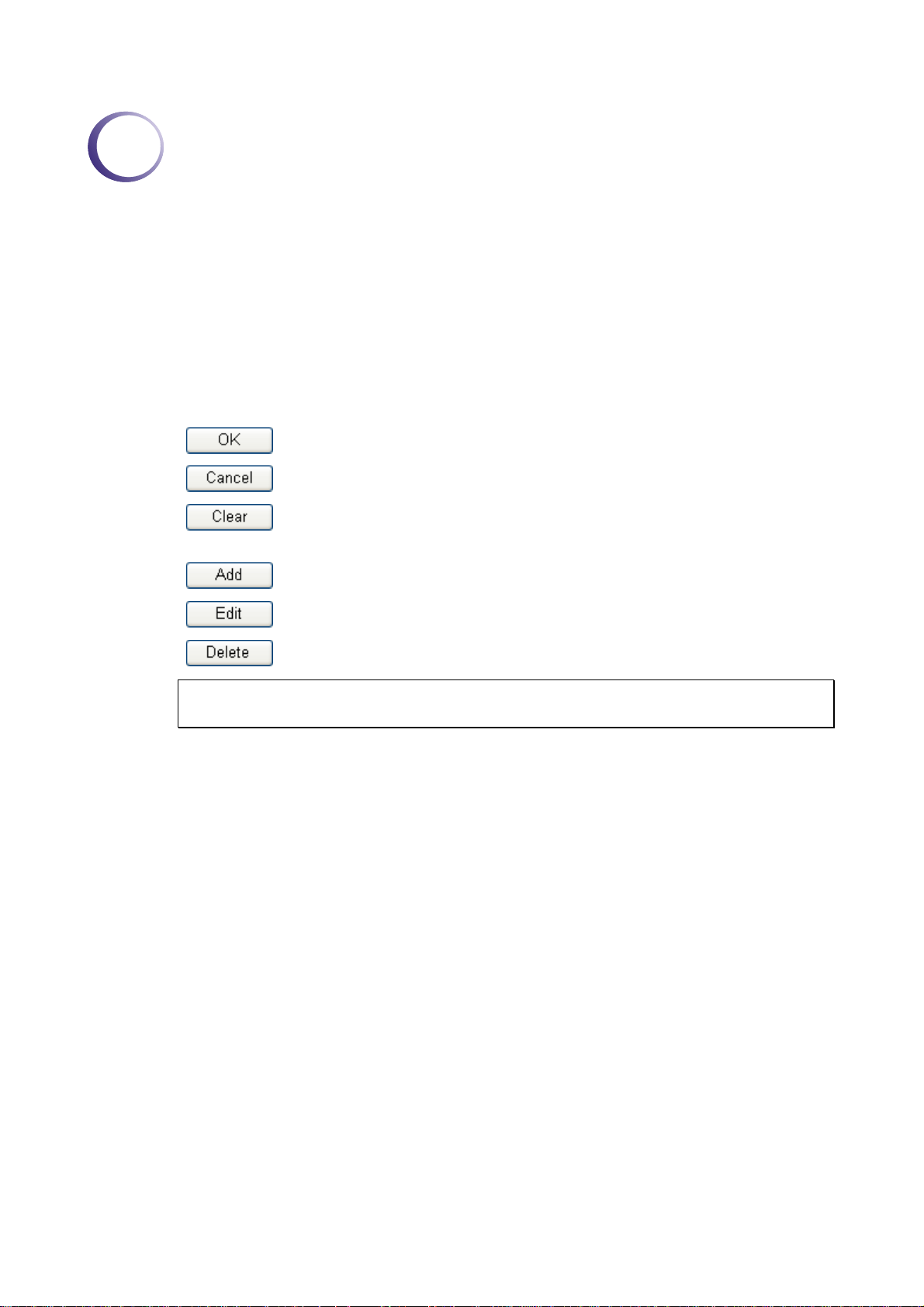
Several main buttons appeared on the web pages are defined as the following:
Save and apply current settings.
Cancel current settings and recover to the previous saved settings.
Clear all the selections and parameters settings, including selection from
drop-down list. All the values must be reset with factory default settings.
Add new settings for specified item.
TM
).
Edit the settings for the selected item.
Delete the selected item with the corresponding settings.
Note: For the other buttons shown on the web pages, please refer to Chapter 4 for
detailed explanation.
11..22 LLEEDD IInnddiiccaattoorrss aanndd CCoonnnneeccttoorrss
Before you use the Vigor router, please get acquainted with the LED indicators and
connectors first.
The displays of LED indicators and connectors for the routers are different slightly. The
following sections will introduce them respectively.
Vigor2950 Series User’s Guide
1
Page 12
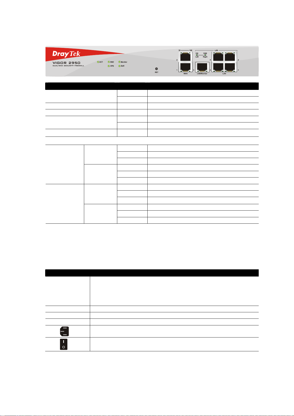
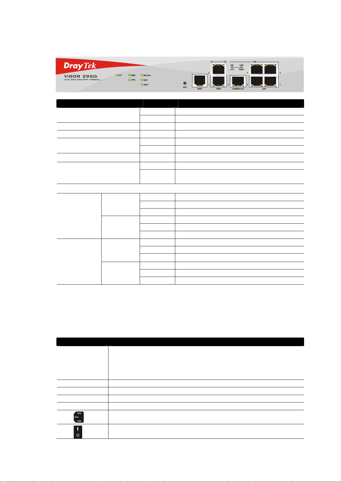
11..22..11 FFoorr VViiggoorr22995500
LED Status Explanation
Blinking The router is powered on and running normally. ACT (Activity)
Off The router is powered off.
DMZ On DMZ Host is specified in certain site.
Monitor On LAN traffic monitor is active.
On The VPN tunnel is launched. VPN
Off The VPN tunnel is closed.
QoS
On The QoS function is active.
LED on Connector
On The port is connected with 10Mbps.
Off The port is disconnected.
Blinking The data is transmitting.
On The port is connected with 100Mbps.
Off The port is disconnected.
Blinking The data is transmitting.
On The port is connected with 100Mbps.
Off The port is disconnected.
Blinking The data is transmitting.
On The port is connected with 1000Mbps.
Off The port is disconnected.
Blinking The data is transmitting.
WAN
LAN/Monitor
LAN
10
(left LED)
100
(right LED)
100
(left LED)
1000
(right LED)
Interface Description
RST
(Factory Reset)
WAN(1/2) Connecter for remote netw or k e d devi ces .
LAN/Monitor Connecter for local networked devices.
LAN (1-4) Connecter for local networked devices.
2
Restore the default settings.
Usage: Turn on the router (ACT LED is blinking). Press the hole and keep for
more than 5 seconds. When you see the ACT LED begins to blink rapidly than
usual, release the button. Then the router will restart with the factory default
configuration.
Connecter for a power cord with 100-240VAC (inlet).
Power Switch. “1” is ON; “0” is OFF.
Vigor2950 Series User’s Guide
Page 13
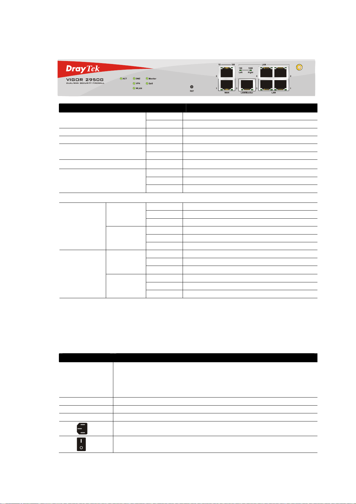
11..22..22 FFoorr VViiggoorr22995500GG
LED Status Explanation
Blinking The router is powered on and running normally. ACT (Activity)
Off The router is powered off.
DMZ On DMZ Host is specified in certain site.
Monitor On LAN traffic monitor is active.
On The VPN tunnel is launched. VPN
Off The VPN tunnel is closed.
QoS
WLAN
On The QoS function is active.
On Wireless access point is ready.
Blinking Ethernet packets are transmitting over wireless LAN.
Off The WLAN function is inactive.
LED on Connector
On The port is connected with 10Mbps.
Off The port is disconnected.
Blinking The data is transmitting.
On The port is connected with 100Mbps.
Off The port is disconnected.
Blinking The data is transmitting.
On The port is connected with 100Mbps.
Off The port is disconnected.
Blinking The data is transmitting.
On The port is connected with 1000Mbps.
Off The port is disconnected.
Blinking The data is transmitting.
WAN
LAN/Monitor
LAN
10
(left LED)
100
(right LED)
100
(left LED)
1000
(right LED)
Interface Description
RST
(Factory Reset)
WAN(1/2) Connecter for remote netw or k e d devi ces .
LAN/Monitor Connecter for local networked devices.
LAN (1-4) Connecter for local networked devices.
Vigor2950 Series User’s Guide
Restore the default settings.
Usage: Turn on the router (ACT LED is blinking). Press the hole and keep for
more than 5 seconds. When you see the ACT LED begins to blink rapidly than
usual, release the button. Then the router will restart with the factory default
configuration.
Connecter for a power cord with 100-240VAC (inlet).
Power Switch. “1” is ON; “0” is OFF.
3
Page 14
11..22..33 FFoorr VViiggoorr22995500ii
LED Status Explanation
Blinking The router is powere d on and ru n ni n g no rmally. ACT (Activity)
Off The router is powered off.
DMZ On DMZ Host is specified in certain site.
Monitor On LAN traffic monitor is active.
On The VPN tunnel is launched. VPN
Off The VPN tunnel is closed.
QoS
ISDN
On The QoS function is active.
On The ISDN service function is active.
Blinking A successful connection on the ISDN BRI B1/B2
channel.
LED on Connector
On The port is connected with 10Mbps.
Off The port is disconnected.
Blinking The data is transmitting.
On The port is connected with 100Mbps.
Off The port is disconnected.
Blinking The data is transmitting.
On The port is connected with 100Mbps.
Off The port is disconnected.
Blinking The data is transmitting.
On The port is connected with 1000Mbps.
Off The port is disconnected.
Blinking The data is transmitting.
WAN
LAN/Monitor
LAN
10
(left LED)
100
(right LED)
100
(left LED)
1000
(right LED)
Interface Description
RST
(Factory Reset)
ISDN Connect for NT1 (or NT1+) box provided by ISDN service provider.
WAN(1/2) Connecter for remote netw or k e d devi ces .
LAN/Monitor Connecter for local networked devices.
LAN (1- 4) Connecter for local networked devices.
4
Restore the default settings.
Usage: Turn on the router (ACT LED is blinking). Press the hole and keep for
more than 5 seconds. When you see the ACT LED begins to blink rapidly than
usual, release the button. Then the router will restart with the factory default
configuration.
Connecter for a power cord with 100-240VAC (inlet).
Power Switch. “1” is ON; “0” is OFF.
Vigor2950 Series User’s Guide
Page 15
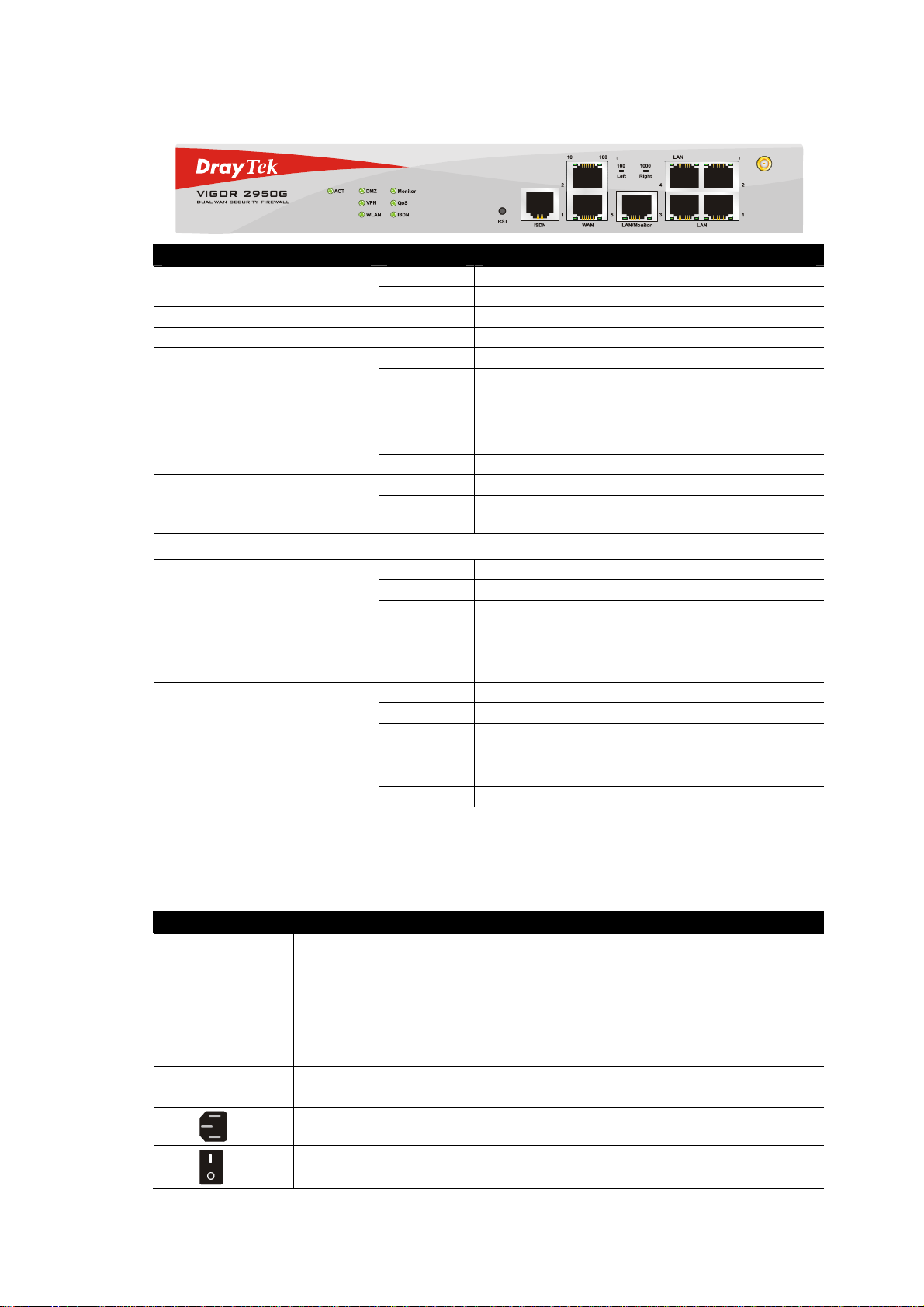
11..22..44 FFoorr VViiggoorr22995500GGii
LED Status Explanation
Blinking The router is powered on and running normally. ACT (Activity)
Off The router is powered off.
DMZ On DMZ Host is specified in certain site.
Monitor On LAN traffic monitor is active.
On The VPN tunnel is launched. VPN
Off The VPN tunnel is closed.
QoS
WLAN
ISDN
On The QoS function is active.
On Wireless access point is ready.
Blinking Ethernet packets are transmitting over wireless LAN.
Off The WLAN function is inactive.
On The ISDN service function is active.
Blinking A successful connection on the ISDN BRI B1/B2
channel.
LED on Connector
On The port is connected with 10Mbps.
Off The port is disconnected.
Blinking The data is transmitting.
On The port is connected with 100Mbps.
Off The port is disconnected.
Blinking The data is transmitting.
On The port is connected with 100Mbps.
Off The port is disconnected.
Blinking The data is transmitting.
On The port is connected with 1000Mbps.
Off The port is disconnected.
Blinking The data is transmitting.
WAN
LAN/Monitor
LAN
10
(left LED)
100
(right LED)
100
(left LED)
1000
(right LED)
Interface Description
RST
(Factory Reset)
ISDN Connect for NT1 (or NT1+) box provided by ISDN service provider.
WAN(1/2) Connecter for remote netw or k e d devi ces .
LAN/Monitor Connecter for local networked devices.
LAN (1- 4) Connecter for local networked devices.
Vigor2950 Series User’s Guide
Restore the default settings.
Usage: Turn on the router (ACT LED is blinking). Press the hole and keep for
more than 5 seconds. When you see the ACT LED begins to blink rapidly than
usual, release the button. Then the router will restart with the factory default
configuration.
Connecter for a power cord with 100-240VAC (inlet).
Power Switch. “1” is ON; “0” is OFF.
5
Page 16
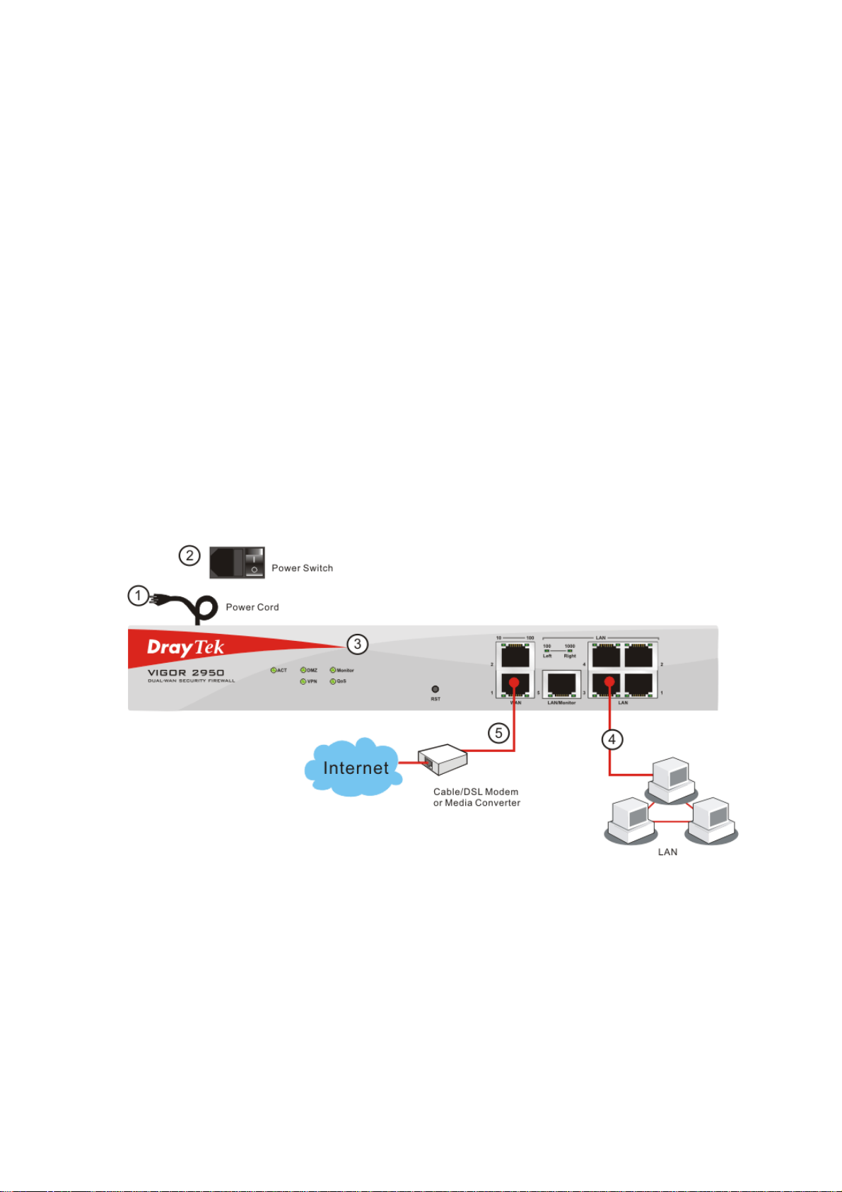
11..33 HHaarrddwwaarree IInnssttaallllaattiioonn
Before starting to configure the router, you have to connect your devices correctly.
1. Connect the power cord to the router’s power port on the rear panel, and the other side
into a wall outlet.
2. Power on the device by pressing down the power switch on the rear panel.
3. The system starts to initiate. After completing the system test, the ACT LED will light
up and start blinking.
4. Connect one end of an Ethernet cable (RJ-45) to one of the LAN ports of the router and
the other end of the cable (RJ-45) into the Ethernet port on your computer (that device
also can connect to other computers to form a small area network). The LAN LED
(Left or Right) will light up according to the network card feature (1000 or 100) of the
device that it connected.
5. Connect a cable Modem/DSL Modem/Media Converter (depends on your requirement)
to any WAN port of router with Ethernet cable (RJ-45). The WAN1/WAN2 LED (Left
or Right) will light up according to the network card feature (100 or 10) of the device
that it connected.
(For the detailed information of LED status, please refer to section 1.1.)
6
Vigor2950 Series User’s Guide
Page 17
2
Coonnffiigguurriinngg
C
For use the router properly, it is necessary for you to change the password of web
configuration for security and adjust primary basic settings.
This chapter explains how to setup a password for an administrator and how to adjust basic
settings for accessing Internet successfully. Be aware that only the administrator can change
the router configuration.
22..11 CChhaannggiinngg PPaasssswwoorrdd
To change the password for this device, you have to access into the web browse with default
password first.
1. Make sure your computer connects to the router correctly.
Notice: You may either simply set up your computer to get IP dynamically
from the router or set up the IP address of the computer to be the same
subnet as the default IP address of Vigor router 192.168.1.1. For the
detailed information, please refer to the later section - Trouble Shooting of
this guide.
Baassiicc
B
Seettttiinnggss
S
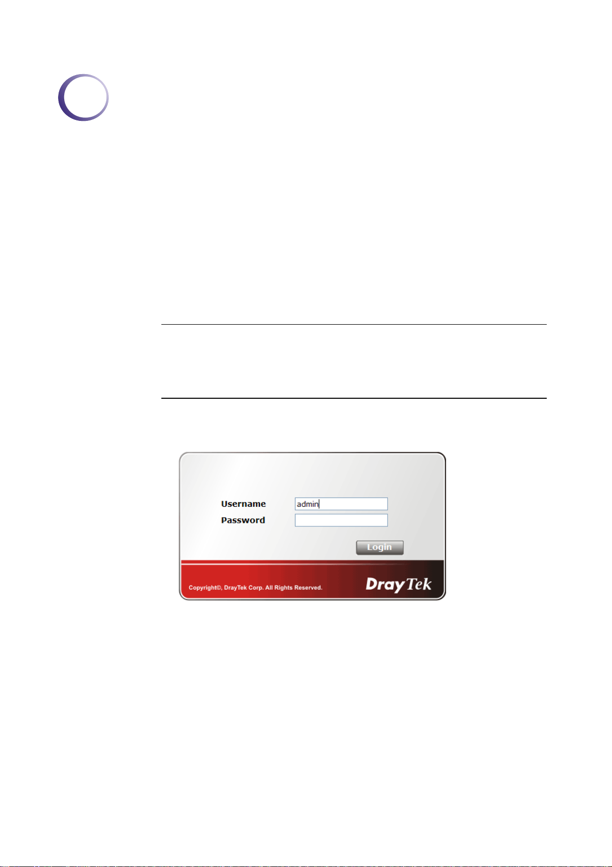
2. Open a web browser on your PC and type http://192.168.1.1. A pop-up window will
open to ask for username and password. Please type “admin” as the username and leave
blank for the password on the window. Next click OK for next screen.
Vigor2950 Series User’s Guide
7
Page 18
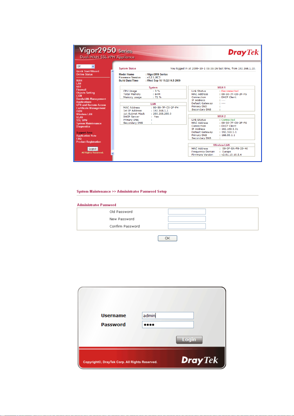
3. Now, the Main Screen will pop up.
Home Page for Vigor2950 Series
4. 4Go to System Maintenance page and choose Administrator Password.
5. Enter the login password (the default is blank) on the field of Old Password. Type a
new one in the field of New Password and retype it on the field of Confirm Password.
Then click OK to continue.
6. Now, the password has been changed. Next time, use the new password to access the
Web Configurator for this router.
8
Vigor2950 Series User’s Guide
Page 19
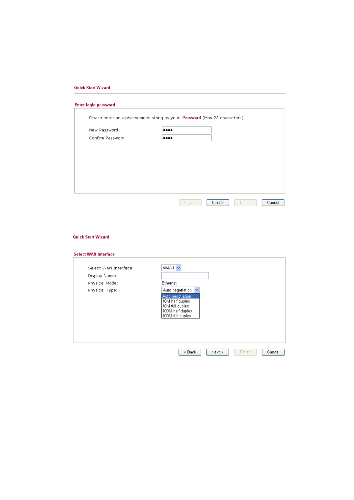
22..22 QQuuiicckk SSttaarrtt WWiizzaarrdd
If your router can be under an environment with high speed NAT, the configuration provide
here can help you to deploy and use the router quickly. The first screen of Quick Start
Wizard is entering login password. After typing the password, please click Next.
On the next page as shown below, please select the WAN interface that you use. Choose
Auto negotiation as the physical type for your router. Then click Next for next step.
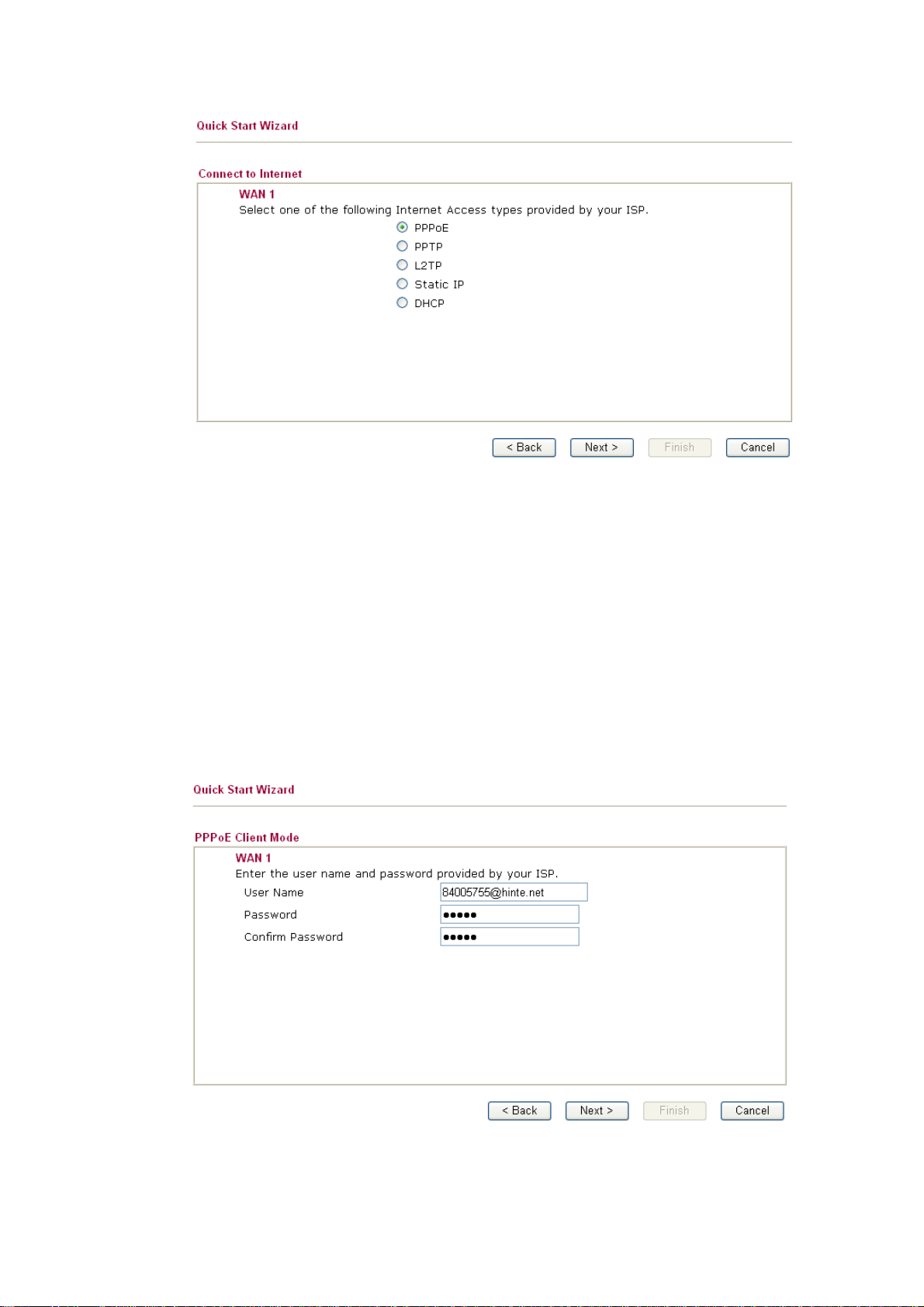
On the next page as shown below, please select the appropriate Internet access type
according to the information from your ISP. For example, you should select PPPoE mode if
the ISP provides you PPPoE interface. Then click Next for next step.
Vigor2950 Series User’s Guide
9
Page 20
In the Quick Start Wizard, you can configure the router to access the Internet with different
protocol/modes such as PPPoE, PPTP, L2TP, Static IP or DHCP. The router supports the
DSL WAN interface for Internet access.
22..22..11 PPPPPPooEE
PPPoE stands for Point-to-Point Protocol over Ethernet. It relies on two widely accepted
standards: PPP and Ethernet. It connects users through an Ethernet to the Internet with a
common broadband medium, such as a single DSL line, wireless device or cable modem. All
the users over the Ethernet can share a common connection.
PPPoE is used for most of DSL modem users. All local users can share one PPPoE
connection for accessing the Internet. Your service provider will provide you information
about user name, password, and authentication mode.
If your ISP provides you the PPPoE connection, please select PPPoE for this router. The following page will be shown:
10
User Name Assign a specific valid user name provided by the ISP.
Vigor2950 Series User’s Guide
Page 21
Password Assign a valid password provided by the ISP.
Confirm Password Retype the password to confirm it.
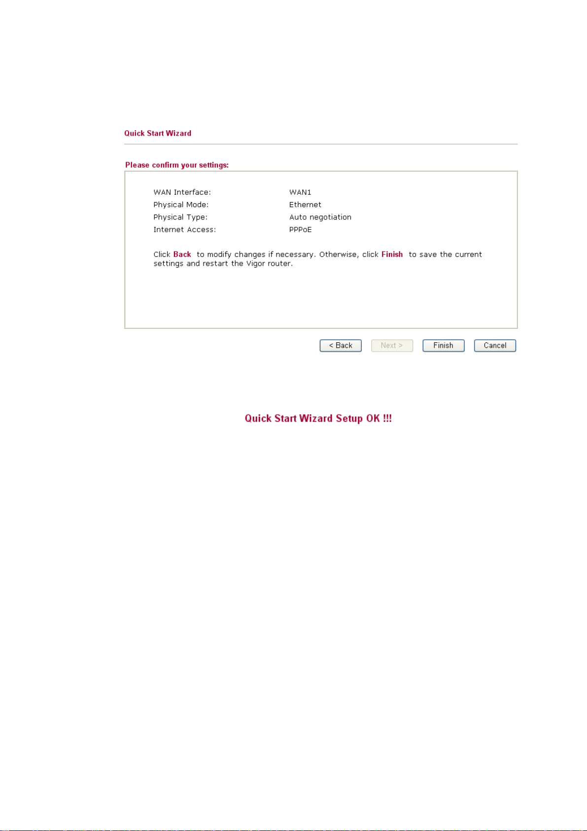
Click Next for viewing summary of such connection.
Click Finish. A page of Quick Start Wizard Setup OK!!! will appear. Then, the system
status of this protocol will be shown.
Vigor2950 Series User’s Guide
11
Page 22
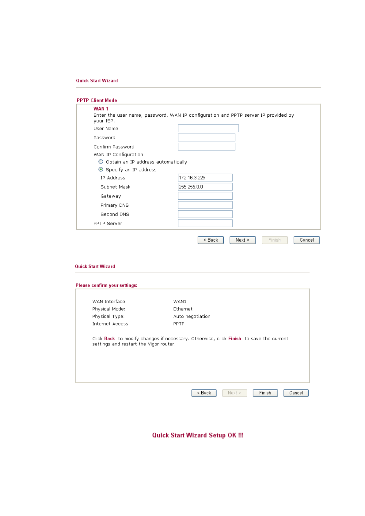
22..22..22 PPPPTTPP
Click PPTP as the protocol. Type in all the information that your ISP provides for this protocol.
Click Next for viewing summary of such connection.
Click Finish. A page of Quick Start Wizard Setup OK!!! will appear. Then, the system
status of this protocol will be shown.
12
Vigor2950 Series User’s Guide
Page 23
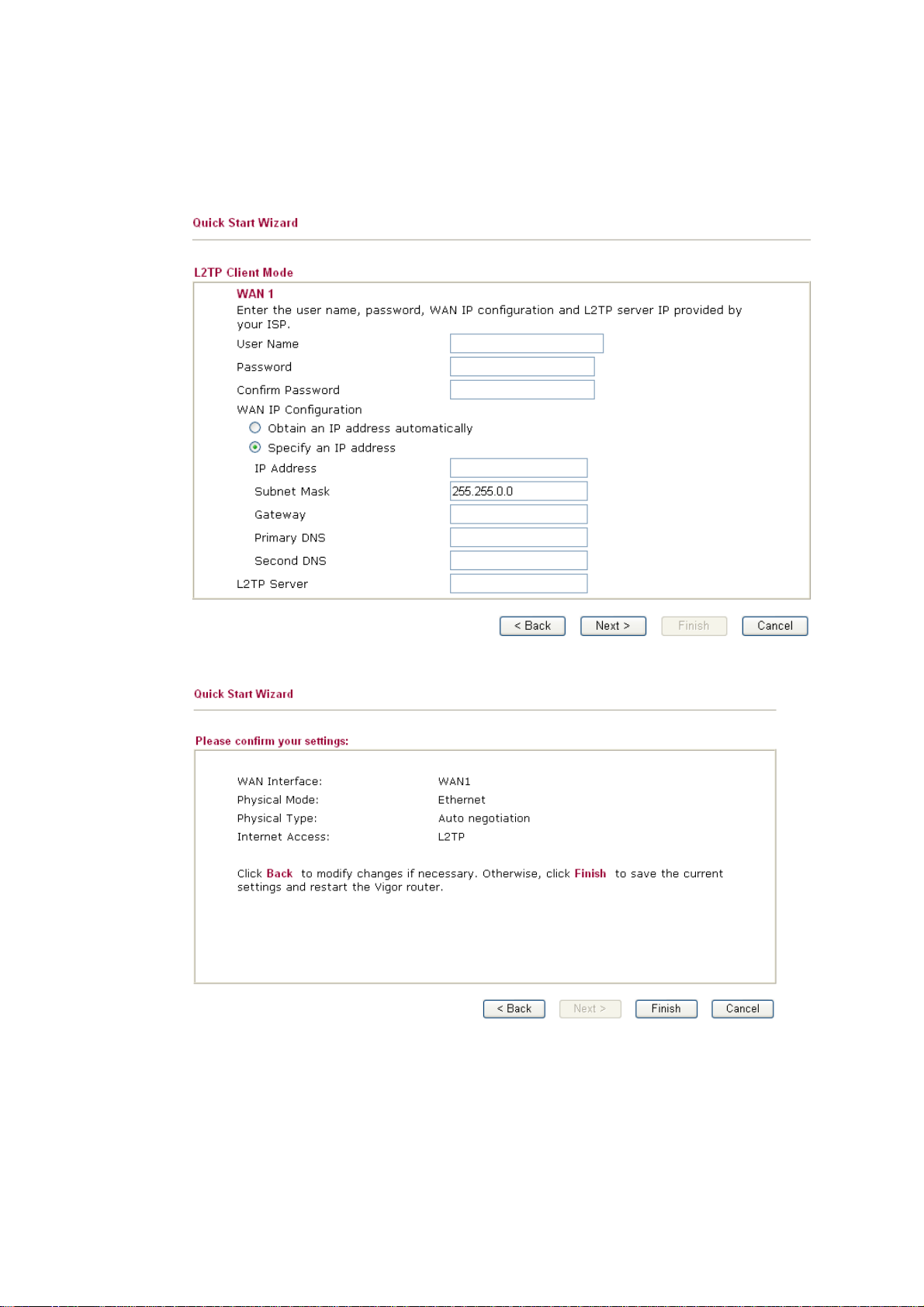
22..22..33 LL22TTPP
Click L2TP as the protocol. Type in all the information that your ISP provides for this protocol.
After finishing the settings in this page, click Next to see the following page.
Vigor2950 Series User’s Guide
13
Page 24
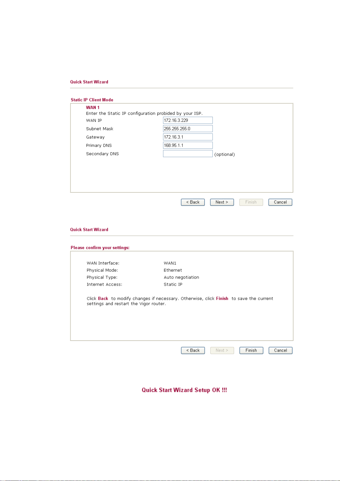
22..22..44 SSttaattiicc IIPP
Click Static IP as the protocol. Type in all the information that your ISP provides for this protocol.
After finishing the settings in this page, click Next to see the following page.
14
Click Finish. A page of Quick Start Wizard Setup OK!!! will appear. Then, the system
status of this protocol will be shown.
Vigor2950 Series User’s Guide
Page 25

22..22..55 DDHHCCPP
Click DHCP as the protocol. Type in all the information that your ISP provides for this protocol.
After finishing the settings in this page, click Next to see the following page.
Click Finish. A page of Quick Start Wizard Setup OK!!! will appear. Then, the system
status of this protocol will be shown.
Vigor2950 Series User’s Guide
15
Page 26
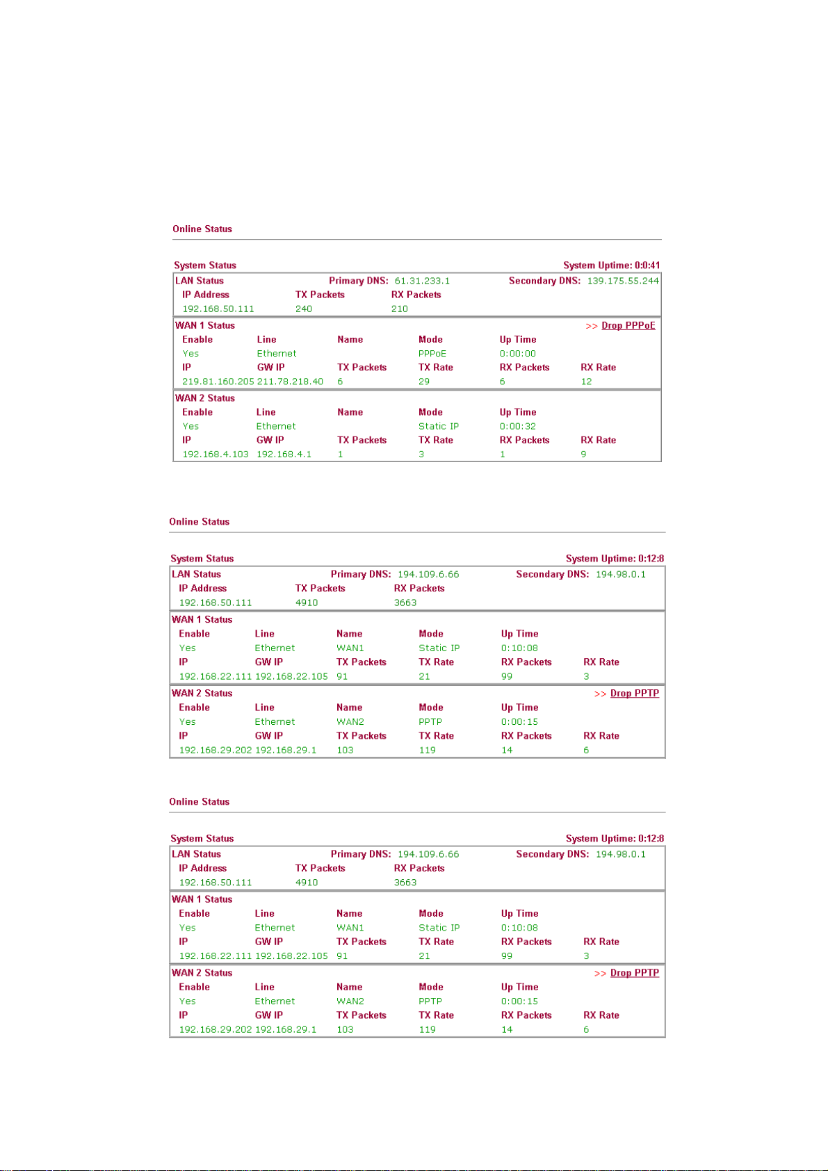
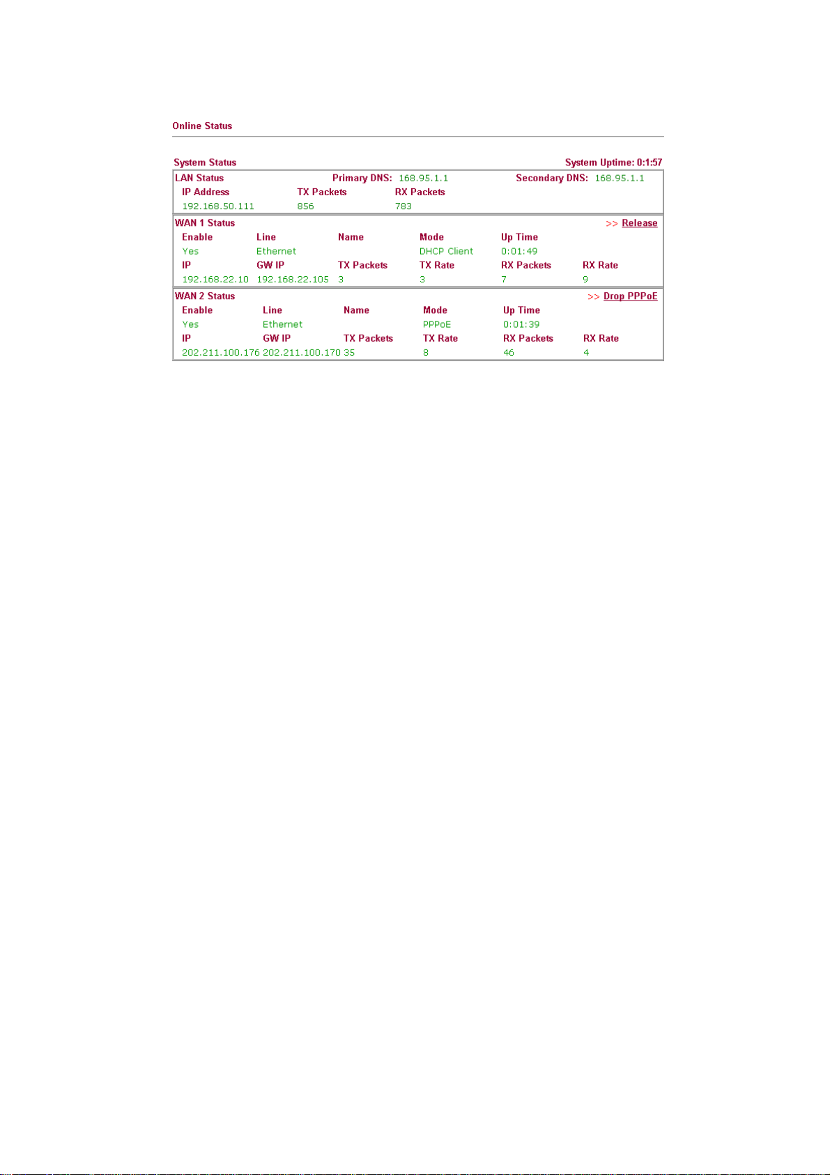
22..33 OOnnlliinnee SSttaattuuss
The online status shows the system status, WAN status, ADSL Information and other status
related to this router within one page. If you select PPPoE/PPTP as the protocol, you will
find out a link of Dial PPPoE or Drop PPPoE in the Online Status web page.
Online status for PPPoE
Online status for PPTP (for WAN2)
16
Online status for Static IP (for WAN1)
Vigor2950 Series User’s Guide
Page 27
Online status for DHCP
Detailed explanation is shown below:
Primary DNS Display the IP address of the primary DNS.
Secondary DNS Display the IP address of the secondary DNS.
LAN Status
IP Address Display the IP address of the LAN interface.
TX Packets Display the total transmitted packets at the LAN interface.
RX Packets Display the total number of received packets at the LAN interface.
WAN1/2 Status
Line Display the physical connection (Ethernet) of this interface.
Name Display the name set in WAN1/WAN web page.
Mode Display the type of WAN connection (e.g., PPPoE).
Up Time Display the total uptime of the interface.
IP Display the IP address of the WAN interface.
GW IP Display the IP address of the default gateway.
TX Packets Display the total transmitted packets at the WAN interface.
TX Rate Display the speed of transmitted octets at the WAN interface.
RX Packets Display the total number of received packets at the WAN interface.
RX Rate Display the speed of received octets at the WAN interface.
ISDN Status
Channel Active Conn. Display the active connection status for each channel.
TX Pkts Display the total transmitted packets at the ISDN interface.
TX Rate Display the speed of transmitted octets at the ISDN interface.
RX Pkts Display the total number of received packets at the ISDN interface.
RX Rate Display the speed of received octets at the ISDN interface.
Up Time Display the total uptime of the interface.
AOC Display the charge information of the interface.
Dial ISDN Allows you to dial ISDN connection.
Vigor2950 Series User’s Guide
17
Page 28

Drop B1/B2 Allows you to drop B1 or B2 connection.
Note: The words in green mean that the WAN connection of that interface
(WAN1/WAN2) is ready for accessing Internet; the words in red mean that the
WAN connection of that interface (WAN1/WAN2) is not ready for accessing
Internet.
22..44 SSaavviinngg CCoonnffiigguurraattiioonn
Each time you click OK on the web page for saving the configuration, you can find
messages showing the system interaction with you.
Ready indicates the system is ready for you to input settings.
Settings Saved means your settings are saved once you click Finish or OK button.
18
Vigor2950 Series User’s Guide
Page 29

3
Addvvaanncceedd
A
After finished basic configuration of the router, you can access Internet with ease. For the
people who want to adjust more setting for suiting his/her request, please refer to this chapter
for getting detailed information about the advanced configuration of this router. As for other
examples of application, please refer to chapter 4.
33..11 WWAANN
33..11..11 BBaassiiccss ooff IInntteerrnneett PPrroottooccooll ((IIPP)) NNeettwwoorrkk
Quick Start Wizard offers user an easy method to quick setup the connection mode for the router. Moreover, if you want to adjust more settings for different WAN modes, please go to WAN group and click the Internet Access link.
IP means Internet Protocol. Every device in an IP-based Network including routers, print
server, and host PCs, needs an IP address to identify its location on the network. To avoid
address conflicts, IP addresses are publicly registered with the Network Information Centre
(NIC). Having a unique IP address is mandatory for those devices participated in the public
network but not in the private TCP/IP local area networks (LANs), such as host PCs under
the management of a router since they do not need to be accessed by the public. Hence, the
NIC has reserved certain addresses that will never be registered publicly. These are known as
private IP addresses, and are listed in the following ranges:
Weebb
W
Coonnffiigguurraattiioonn
C
From 10.0.0.0 to 10.255.255.255
From 172.16.0.0 to 172.31.255.255
From 192.168.0.0 to 192.168.255.255
WWhhaatt aarree PPuubblliicc IIPP AAddddrreessss aanndd PPrriivvaattee IIPP AAddddrreessss
As the router plays a role to manage and further protect its LAN, it interconnects groups of
host PCs. Each of them has a private IP address assigned by the built-in DHCP server of the
Vigor router. The router itself will also use the default private IP address: 192.168.1.1 to
communicate with the local hosts. Meanwhile, Vigor router will communicate with other
network devices through a public IP address. When the data flow passing through, the
Network Address Translation (NAT) function of the router will dedicate to translate
public/private addresses, and the packets will be delivered to the correct host PC in the local
area network. Thus, all the host PCs can share a common Internet connection.
GGeett YYoouurr PPuubblliicc IIPP AAddddrreessss ffrroomm IISSPP
In ADSL deployment, the PPP (Point to Point)-style authentication and authorization is
required for bridging customer premises equipment (CPE). Point to Point Protocol over
Ethernet (PPPoE) connects a network of hosts via an access device to a remote access
concentrator or aggregation concentrator. This implementation provides users with
significant ease of use. Meanwhile it provides access control, billing, and type of service
according to user requirement.
When a router begins to connect to your ISP, a serial of discovery process will occur to ask
for a connection. Then a session will be created. Your user ID and password is authenticated
via PAP or CHAP with RADIUS authentication system. And your IP address, DNS server,
and other related information will usually be assigned by your ISP.
Vigor2950 Series User’s Guide
19
Page 30
Below shows the menu items for Internet Access.
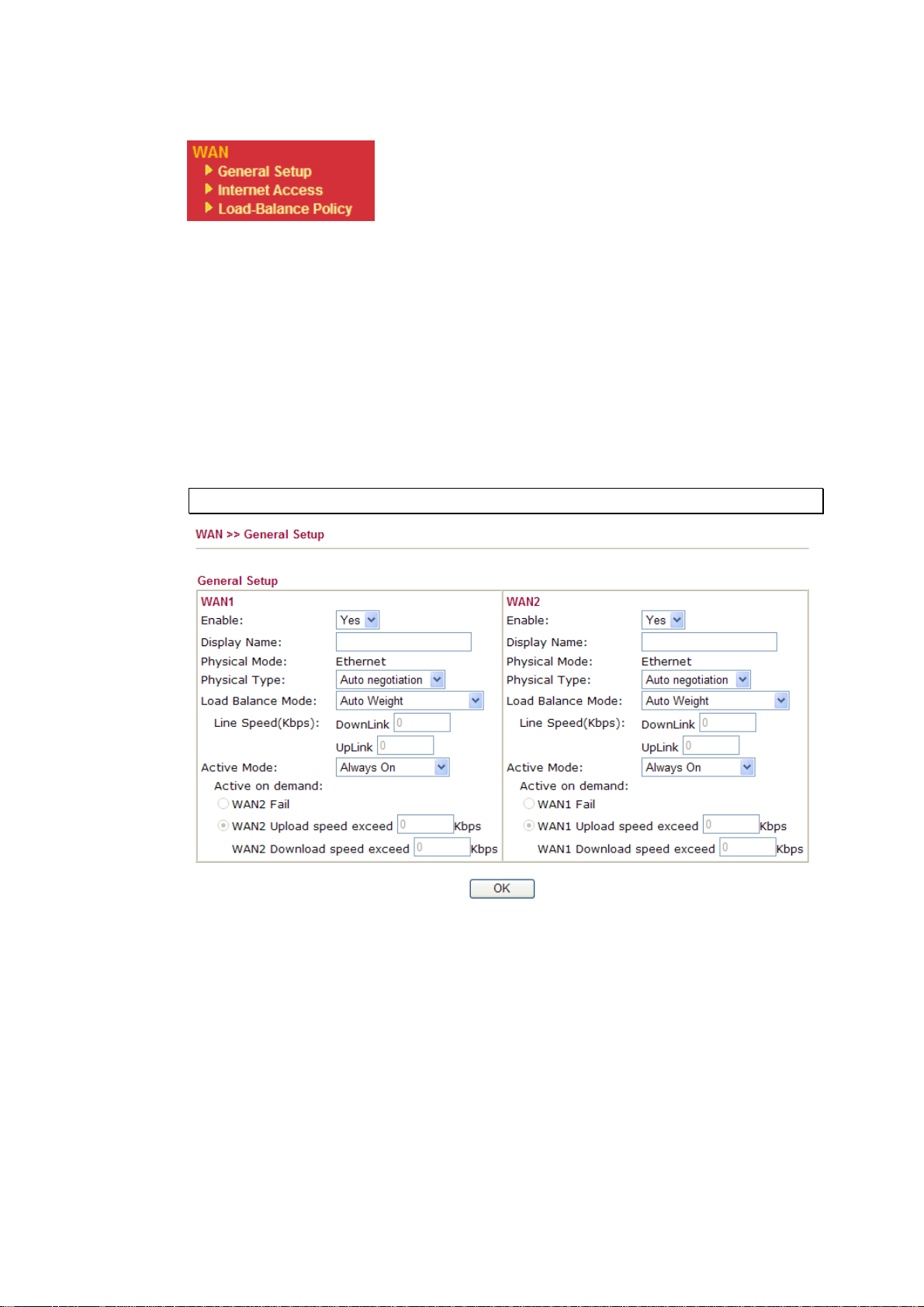
33..11..22 GGeenneerraall SSeettuupp
This section will introduce some general settings of Internet and explain the connection
modes for WAN1 and WAN2 in details.
This router supports dual WAN function. It allows users to access Internet and combine the
bandwidth of the dual WAN to speed up the transmission through the network. Each WAN
port can connect to different ISPs, Even if the ISPs use different technology to provide
telecommunication service (such as DSL, Cable modem, etc.). If any connection problem
occurred on one of the ISP connections, all the traffic will be guided and switched to the
normal communication port for proper operation. Please configure WAN1 and WAN2
settings.
This webpage allows you to set general setup for WAN1 and WAN respectively.
Note: In default, WAN1 and WAN2 are enabled.
20
Enable Choose Yes to invoke the settings for this WAN interface.
Choose No to disable the settings for this WAN interface.
Display Name Type the description for the WAN1/WAN2 interface.
Physical Mode For WAN1, the physical connection is done through ADSL
port; yet the physical connection for WAN2 is done through
an Ethernet port (P1). You cannot change it.
Vigor2950 Series User’s Guide
Page 31
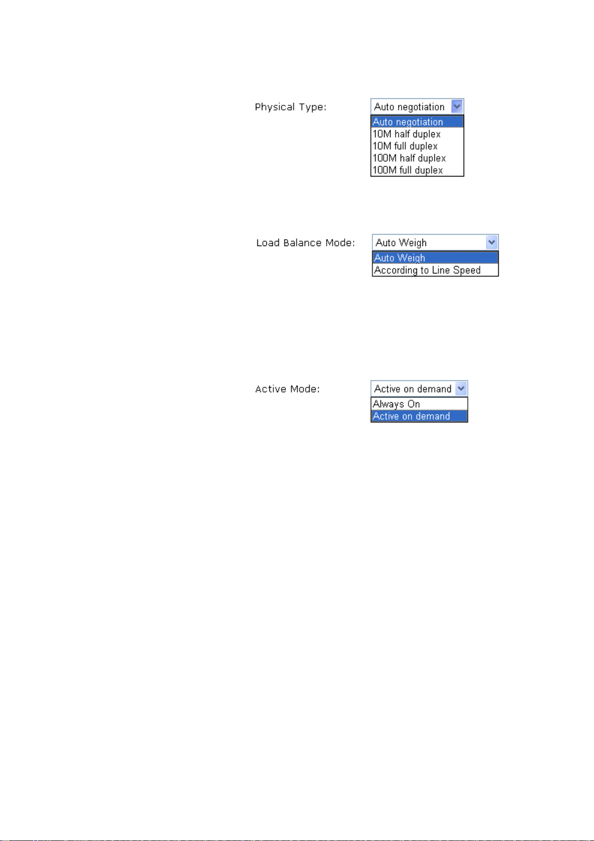
Physical Type You can change the physical type for WAN2 or choose Auto
negotiation for determined by the system.
Load Balance Mode If you know the practical bandwidth for your WAN interface,
please choose the setting of According to Line Speed.
Otherwise, please choose Auto Weigh to let the router reach
the best load balance.
Line Speed If you choose According to Line Speed as the Load Balance
Mode, please type the line speed for downloading and
uploading through WAN1/WAN2. The unit is kbps.
Active Mode Choose Always On to make the WAN connection
(WAN1/WAN2) being activated always; or choose Active on
demand to make the WAN connection (WAN1/WAN2)
activated if it is necessary.
If you choose Active on demand, the Idle Timeout will be
available for you to set for PPPoE and PPTP access modes in
the Details Page of WAN>>Internet Access. In addition, there
are three selections for you to choose for different purposes.
WAN2 Fail – It means the connection for WAN1 will be
activated when WAN2 is failed.
WAN2 Upload speed exceed XX kbps – It means the
connection for WAN1 will be activated when WAN2 Upload
speed exceed certain value that you set in this box for 15
seconds.
WAN2 Download speed exceed XX kbps– It means the
connection for WAN1 will be activated when WAN2
Download speed exceed certain value that you set in this box
for 15 seconds.
WAN1 Fail – It means the connection for WAN2 will be
activated when WAN1 is failed.
WAN1 Upload speed exceed XX kbps – It means the
connection for WAN2 will be activated when WAN1 Upload
speed exceed certain value that you set in this box for 15
seconds.
WAN1 Download speed exceed XX kbps– It means the
connection for WAN2 will be activated when WAN1
Download speed exceed certain value that you set in this box
for 15 seconds.
Vigor2950 Series User’s Guide
21
Page 32

33..11..33 IInntteerrnneett AAcccceessss
For the router supports dual WAN function, the users can set different WAN settings (for
WAN1/WAN2) for Internet Access. Due to different physical mode for WAN1 and WAN2,
the Access Mode for these two connections also varies slightly.
Index It shows the WAN modes that this router supports. WAN1 is the
Display Name It shows the name of the WAN1/WAN2 that entered in general
Physical Mode It shows the physical port for WAN1/WAN2.
Access Mode Use the drop down list to choose a proper access mode. The details
default WAN interface for accessing into the Internet. WAN2 is
the optional WAN interface for accessing into the Internet when
WAN 1 is inactive for some reason.
setup.
page of that mode will be popped up. If not, click Details Page for
accessing the page to configure the settings.
There are three access modes provided for PPPoE, Static or
Dynamic IP and PPTP/L2TP.
Details Page This button will open different web page according to the access
mode that you choose in WAN1 or WAN2.
22
Vigor2950 Series User’s Guide
Page 33

DDeettaaiillss PPaaggee ffoorr PPPPPPooEE
To use PPPoE as the accessing protocol of the internet, please choose Internet Access from
WAN menu. Then, select PPPoE mode for WAN2. The following web page will be shown.
PPPoE Client Mode Click Enable for activating this function. If you click Disable, this
function will be closed and all the settings that you adjusted in this
page will be invalid.
ISP Access Setup Enter your allocated username, password and authentication
parameters according to the information provided by your ISP. If
you want to connect to Internet all the time, you can check Always
On.
Username – Type in the username provided by ISP in this field.
Password – Type in the password provided by ISP in this field.
Index (1-15) in Schedule Setup - You can type in four sets of time
schedule for your request. All the schedules can be set previously
in Application – Schedule web page and you can use the number
that you have set in that web page.
ISDN Dial Backup
Setup
This setting is available for the routers supporting ISDN function
only. Before utilizing the ISDN dial backup feature, you must
create a dial backup profile first.
None - Disable the backup function.
Packet Trigger -The backup line is not on until a packet from a
local host triggers the router to establish a connection.
This setting is available for i model only.
WAN Connection
Detection
Vigor2950 Series User’s Guide
Such function allows you to verify whether network connection is
alive or not through ARP Detect or Ping Detect.
Mode – Choose ARP Detect or Ping Detect for the system to
execute for WAN detection.
23
Page 34

Ping IP – If you choose Ping Detect as detection mode, you have
to type IP address in this field for pinging.
TTL (Time to Live) – Display value for your reference. TTL
value is set by telnet command.
PPP/MP Setup PPP Authentication – Select PAP only or PAP or CHAP for
PPP.
Idle Timeout – Set the timeout for breaking down the Internet
after passing through the time without any action. This setting is
active only when the Active on demand option for Active Mode is
selected in WAN>> General Setup page.
MTU Mean maximum transmission unit of one packet. The default value
is 1442.
IP Address
Assignment Method
(IPCP)
Usually ISP dynamically assigns IP address to you each time you
connect to it and request. In some case, your ISP provides service
to always assign you the same IP address whenever you request.
In this case, you can fill in this IP address in the Fixed IP field.
Please contact your ISP before you want to use this function.
WAN IP Alias - If you have multiple public IP addresses and
would like to utilize them on the WAN interface, please use WAN
IP Alias. You can set up to 32 public IP addresses other than the
current one you are using.
24
Fixed IP – Click Yes to use this function and type in a fixed IP
address in the box of Fixed IP Address.
Default MAC Address – You can use Default MAC Address or
specify another MAC address by typing on the boxes of MAC
Address for the router.
Specify a MAC Address – Type the MAC address for the router
manually.
After finishing all the settings here, please click OK to activate them.
Vigor2950 Series User’s Guide
Page 35

DDeettaaiillss PPaaggee ffoorr SSttaattiicc oorr DDyynnaammiicc IIPP
For static IP mode, you usually receive a fixed public IP address or a public subnet, namely
multiple public IP addresses from your DSL or Cable ISP service providers. In most cases, a
Cable service provider will offer a fixed public IP, while a DSL service provider will offer a
public subnet. If you have a public subnet, you could assign an IP address or many IP
address to the WAN interface.
To use Static or Dynamic IP as the accessing protocol of the internet, please choose
Internet Access from WAN menu. Then, select Static or Dynamic IP mode for WAN2.
The following web page will be shown.
Static or Dynamic IP
(DHCP Client)
ISDN Dial Backup
Setup
Keep WAN
Connection
Vigor2950 Series User’s Guide
Click Enable for activating this function. If you click Disable,
this function will be closed and all the settings that you adjusted
in this page will be invalid.
This setting is available for the routers supporting ISDN function
only. Before utilizing the ISDN dial backup feature, you must
create a dial backup profile first. Please click Internet Access
Setup > Dialing to a Single ISP to enter the backup profile.
None - Disable the backup function.
Packet Trigger -The backup line is not on until a packet from a
local host triggers the router to establish a connection.
This setting is available for i model only.
Normally, this function is designed for Dynamic IP environments
because some ISPs will drop connections if there is no traffic
within certain periods of time. Check Enable PING to keep alive
box to activate this function.
PING to the IP - If you enable the PING function, please specify
the IP address for the system to PING it for keeping alive.
25
Page 36

PING Interval - Enter the interval for the system to execute the
PING operation.
WAN Connection
Detection
Such function allows you to verify whether network connection is
alive or not through ARP Detect or Ping Detect.
Mode – Choose ARP Detect or Ping Detect for the system to
execute for WAN detection.
Ping IP – If you choose Ping Detect as detection mode, you have
to type IP address in this field for pinging.
TTL (Time to Live) – Display value for your reference. TTL
value is set by telnet command.
MTU Mean maximum transmission unit of one packet. The default value
is 1442.
RIP Protocol Routing Information Protocol is abbreviated as RIP(RFC1058)
specifying how routers exchange routing tables information. Click
Enable RIP for activating this function.
WAN IP Network
Settings
This group allows you to obtain an IP address automatically and
allows you type in IP address manually.
WAN IP Alias - If you have multiple public IP addresses and
would like to utilize them on the WAN interface, please use WAN
IP Alias. You can set up to 32 public IP addresses other than the
current one you are using. Notice that this setting is available for
WAN1 only.
26
Obtain an IP address automatically – Click this button to obtain
the IP address automatically if you want to use Dynamic IP mode.
Router Name: Type in the router name provided by ISP.
Domain Name: Type in the domain name that you have assigned.
Specify an IP address – Click this radio button to specify some
data if you want to use Static IP mode.
IP Address: Type the IP address.
Subnet Mask: Type the subnet mask.
Vigor2950 Series User’s Guide
Page 37

Gateway IP Address: Type the gateway IP address.
Default MAC Address : Click this radio button to use default MAC
address for the router.
Specify a MAC Address: Some Cable service providers specify a
specific MAC address for access authentication. In such cases you
need to click the Specify a MAC Address and enter the MAC
address in the MAC Address field.
DNS Server IP
Address
Type in the primary IP address for the router if you want to use
Static IP mode. If necessary, type in secondary IP address for
necessity in the future.
Vigor2950 Series User’s Guide
27
Page 38

DDeettaaiillss PPaaggee ffoorr PPPPTTPP//LL22TTPP
To use PPTP/L2TP as the accessing protocol of the internet, please choose Internet Access
from WAN menu. Then, select PPTP/L2TP mode for WAN2/WAN2. The following web
page will be shown.
PPTP/L2TP Client
Mode
Click Enable PPTP to enable a PPTP client to establish a tunnel
to a DSL modem on the WAN interface.
Click Enable L2TP to enable a L2TP client to establish a tunnel
to a DSL modem on the WAN interface.
Click Disable to disable PPTP/L2TP client mode. All the settings
configured in this page will be invalid.
Server Address - Specify the IP address of the PPTP server.
Specify Gateway IP Address - Specify the WAN IP address for
the router if the server is not in the same subnet.
ISP Access Setup Username -Type in the username provided by ISP in this field.
Password -Type in the password provided by ISP in this field.
Index (1-15) in Schedule Setup - You can type in four sets of time
schedule for your request. All the schedules can be set previously
in Application – Schedule web page and you can use the number
that you have set in that web page.
ISDN Dial Backup
Setup
This setting is available for the routers supporting ISDN function
only. Before utilizing the ISDN dial backup feature, you must
create a dial backup profile (configured in ISDN>>Dial to a
Single ISP or Dial to Dual ISPs) first.
None - Disable the backup function.
Packet Trigger -The backup line is not on until a packet from a
local host triggers the router to establish a connection.
28
This setting is available for i model only.
Vigor2950 Series User’s Guide
Page 39

MTU Mean maximum transmission unit of one packet. The default value
is 1442.
PPP Setup PPP Authentication - Select PAP only or PAP or CHAP for PPP.
Idle Timeout - Set the timeout for breaking down the Internet after
passing through the time without any action. This setting is active
only when the Active on demand option for Active Mode is
selected in WAN>> General Setup page.
IP Address
Assignment
Method(IPCP)
Fixed IP - Usually ISP dynamically assigns IP address to you each
time you connect to it and request. In some case, your ISP provides
service to always assign you the same IP address whenever you
request. In this case, you can fill in this IP address in the Fixed IP
field. Please contact your ISP before you want to use this function.
Click Yes to use this function and type in a fixed IP address in the
box.
Fixed IP Address -Type a fixed IP address.
WAN IP Alias - If you have multiple public IP addresses and
would like to utilize them on the WAN interface, please use WAN
IP Alias. You can set up to 32 public IP addresses other than the
current one you are using. Notice that this setting is available for
WAN1 only.
WAN IP Network
Settings
Vigor2950 Series User’s Guide
Default MAC Address – Click this radio button to use default
MAC address for the router.
Specify a MAC Address - Some Cable service providers specify a
specific MAC address for access authentication. In such cases you
need to click the Specify a MAC Address and enter the MAC
address in the MAC Address field.
Obtain an IP address automatically – Click this button to obtain
the IP address automatically.
Specify an IP address – Click this radio button to specify some
data.
29
Page 40

IP Address – Type the IP address.
Subnet Mask – Type the subnet mask.
33..11..44 LLooaadd--BBaallaannccee PPoolliiccyy
This router supports the function of load balancing. It can assign traffic with protocol type,
IP address for specific host, a subnet of hosts, and port range to be allocated in WAN1 or
WAN2 interface. The user can assign traffic category and force it to go to dedicate network
interface based on the following web page setup. Twenty policies of load-balance are
supported by this router.
Note: Load-Balance Policy is running only when both WAN1 and WAN2 are
activated.
Index Click the number of index to access into the load-balance policy
configuration web page.
Enable Check this box to enable this policy.
Protocol Use the drop-down menu to change the protocol for the WAN
interface.
WAN Use the drop-down menu to change the WAN interface.
Src IP Start Display the IP address for the start of the source IP.
Src IP End Display the IP address for the end of the source IP.
Dest IP Start Display the IP address for the start of the destination IP.
Dest IP End Display the IP address for the end of the destination IP.
Dest Port Start Display the IP address for the start of the destination port.
30
Vigor2950 Series User’s Guide
Page 41
Dest Port End Display the IP address for the end of the destination port.
Move UP/Move Down Use Up or Down link to move the order of the policy.
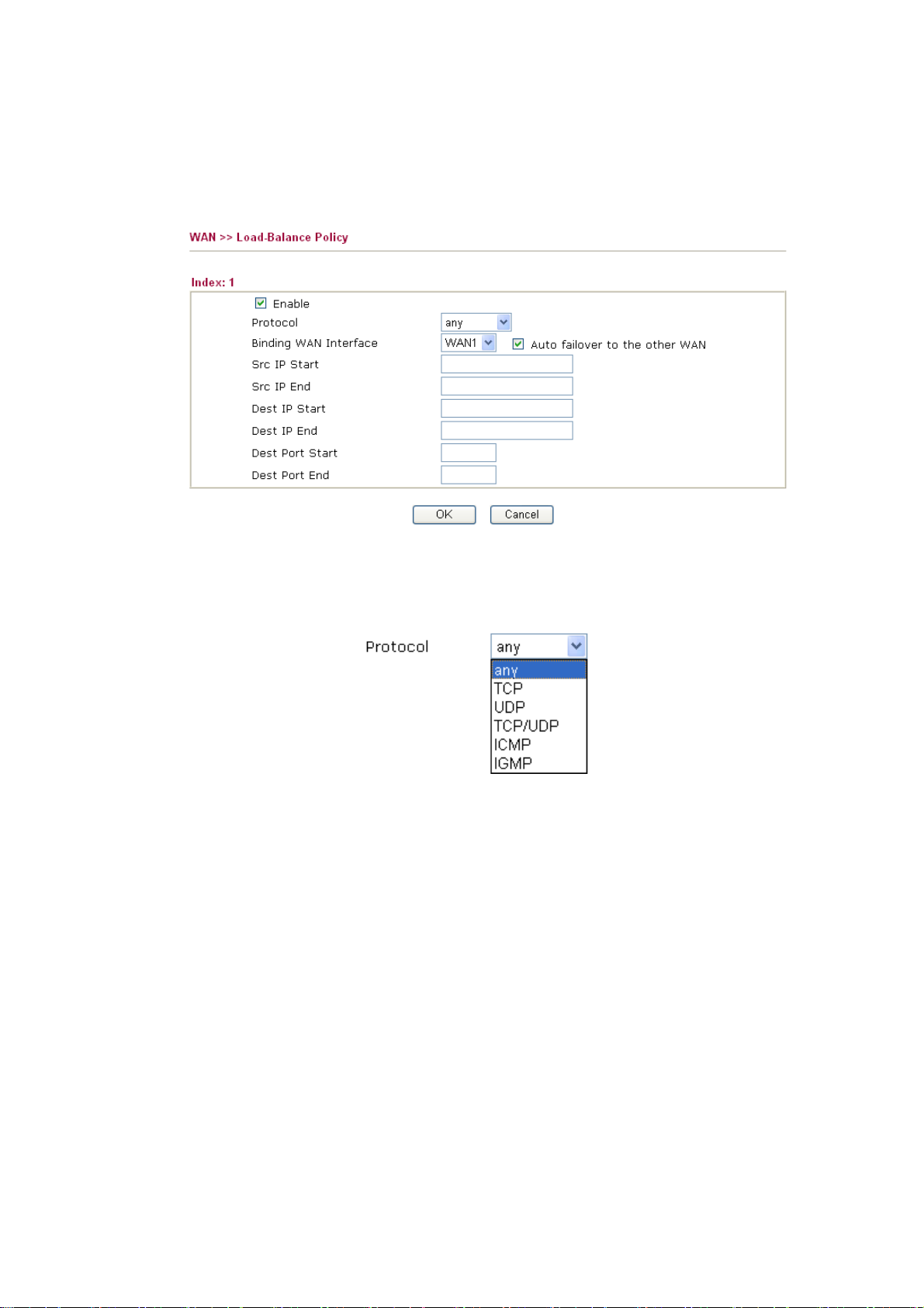
Click Index 1 to access into the following page for configuring load-balance policy.
Enable Check this box to enable this policy.
Protocol Use the drop-down menu to choose a proper protocol for the WAN
interface.
Binding WAN
interface
Choose the WAN interface (WAN1 or WAN2) for binding.
Auto failover to other WAN – Check this button to lead the data
passing through other WAN automatically when the selected
WAN interface is failover.
Src IP Start Type the source IP start for the specified WAN interface.
Src IP End Type the source IP end for the specified WAN interface. If this
field is blank, it means that all the source IPs inside the LAN will
be passed through the WAN interface.
Dest IP Start Type the destination IP start for the specified WAN interface.
Dest IP End Type the destination IP end for the specified WAN interface. If this
Dest Port Start Type the destination port start for the destination IP.
Vigor2950 Series User’s Guide
field is blank, it means that all the destination IPs will be passed
through the WAN interface.
31
Page 42

Dest Port End Type the destination port end for the destination IP. If this field is
blank, it means that all the destination ports will be passed through
the WAN interface.
33..22 LLAANN
Local Area Network (LAN) is a group of subnets regulated and ruled by router. The design
of network structure is related to what type of public IP addresses coming from your ISP.
Note: VLAN menu provided here is available for the router without wireless feature. If the
router you have offers wireless feature, please refer to section 3.13 directly for detailed
information.
33..22..11 BBaassiiccss ooff LLAANN
The most generic function of Vigor router is NAT. It creates a private subnet of your own. As
mentioned previously, the router will talk to other public hosts on the Internet by using
public IP address and talking to local hosts by using its private IP address. What NAT does is
to translate the packets from public IP address to private IP address to forward the right
packets to the right host and vice versa. Besides, Vigor router has a built-in DHCP server that
assigns private IP address to each local host. See the following diagram for a briefly
understanding.
32
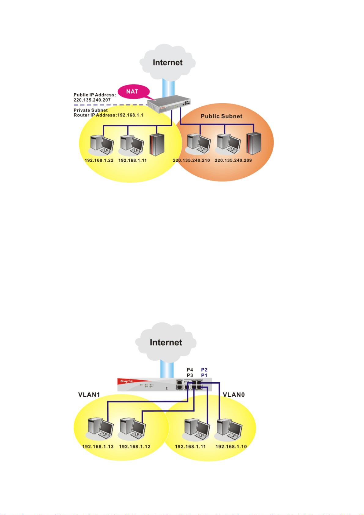
In some special case, you may have a public IP subnet from your ISP such as
220.135.240.0/24. This means that you can set up a public subnet or call second subnet that
each host is equipped with a public IP address. As a part of the public subnet, the Vigor
router will serve for IP routing to help hosts in the public subnet to communicate with other
public hosts or servers outside. Therefore, the router should be set as the gateway for public
hosts.
Vigor2950 Series User’s Guide
Page 43
WWhhaatt iiss RRoouuttiinngg IInnffoorrmmaattiioonn PPrroottooccooll ((RRIIPP))
Vigor router will exchange routing information with neighboring routers using the RIP to
accomplish IP routing. This allows users to change the information of the router such as IP
address and the routers will automatically inform for each other.
WWhhaatt iiss SSttaattiicc RRoouuttee
When you have several subnets in your LAN, sometimes a more effective and quicker way
for connection is the Static routes function rather than other method. You may simply set
rules to forward data from one specified subnet to another specified subnet without the
presence of RIP.
WWhhaatt aarree VViirrttuuaall LLAANNss aanndd RRaattee CCoonnttrrooll
You can group local hosts by physical ports and create up to 4 virtual LANs. To manage the
communication between different groups, please set up rules in Virtual LAN (VLAN)
function and the rate of each.
Vigor2950 Series User’s Guide
33
Page 44

33..22..22 GGeenneerraall SSeettuupp
This page provides you the general settings for LAN. Click LAN to open the LAN settings page and choose General Setup.
1st IP Address Type in private IP address for connecting to a local private network
(Default: 192.168.1.1).
1st Subnet Mask Type in an address code that determines the size of the network.
(Default: 255.255.255.0/ 24)
For IP Routing Usage Click Enable to invoke this function. The default setting is
Disable.
nd
IP Address Type in secondary IP address for connecting to a subnet.
2
(Default: 192.168.2.1/ 24)
nd
Subnet Mask An address code that determines the size of the network.
2
(Default: 255.255.255.0/ 24)
nd
DHCP Server You can configure the router to serve as a DHCP server for the 2nd
2
subnet.
34
Vigor2950 Series User’s Guide
Page 45

Start IP Address: Enter a value of the IP address pool for the
DHCP server to start with when issuing IP addresses. If the 2nd IP
address of your router is 220.135.240.1, the starting IP address
must be 220.135.240.2 or greater, but smaller than
220.135.240.254.
IP Pool Counts: Enter the number of IP addresses in the pool. The
maximum is 10. For example, if you type 3 and the 2nd IP address
of your router is 220.135.240.1, the range of IP address by the
DHCP server will be from 220.135.240.2 to 220.135.240.11.
MAC Address: Enter the MAC Address of the host one by one
and click Add to create a list of hosts to be assigned, deleted or
edited IP address from above pool. Set a list of MAC Address for
nd
2
DHCP server will help router to assign the correct IP address of
the correct subnet to the correct host. So those hosts in 2
won’t get an IP address belonging to 1
st
subnet.
nd
subnet
RIP Protocol Control Disable deactivates the RIP protocol. It will lead to a stoppage of
the exchange of routing information between routers. (Default)
1st Subnet - Select the router to change the RIP information of the
1st subnet with neighboring routers.
2nd Subnet - Select the router to change the RIP information of
the 2nd subnet with neighboring routers.
DHCP Server
Configuration
DHCP stands for Dynamic Host Configuration Protocol. The
router by factory default acts a DHCP server for your network so it
automatically dispatch related IP settings to any local user
configured as a DHCP client. It is highly recommended that you
leave the router enabled as a DHCP server if you do not have a
DHCP server for your network.
If you want to use another DHCP server in the network other than
the Vigor Router’s, you can let Relay Agent help you to redirect the
DHCP request to the specified location.
Enable Server - Let the router assign IP address to every host in
the LAN.
Disable Server – Let you manually assign IP address to every host
in the LAN.
Relay Agent – (1
st
subnet/2nd subnet) Specify which subnet that
DHCP server is located the relay agent should redirect the DHCP
request to.
Start IP Address - Enter a value of the IP address pool for the
DHCP server to start with when issuing IP addresses. If the 1st IP
address of your router is 192.168.1.1, the starting IP address must
be 192.168.1.2 or greater, but smaller than 192.168.1.254.
IP Pool Counts - Enter the maximum number of PCs that you
want the DHCP server to assign IP addresses to. The default is 50
and the maximum is 253.
Gateway IP Address - Enter a value of the gateway IP address for
the DHCP server. The value is usually as same as the 1st IP address
Vigor2950 Series User’s Guide
35
Page 46

of the router, which means the router is the default gateway.
DHCP Server IP Address for Relay Agent - Set the IP address of
the DHCP server you are going to use so the Relay Agent can help
to forward the DHCP request to the DHCP server.
DNS Server
Configuration
DNS stands for Domain Name System. Every Internet host must
have a unique IP address, also they may have a human-friendly,
easy to remember name such as www.yahoo.com. The DNS server
converts the user-friendly name into its equivalent IP address.
Force DNS manual setting -
in this page instead of DNS servers given by the Internet Access
server (PPPoE, PPTP, L2TP or DHCP server).
Primary IP Address -You must specify a DNS server IP address
here because your ISP should provide you with usually more than
one DNS Server. If your ISP does not provide it, the router will
automatically apply default DNS Server IP address: 194.109.6.66
to this field.
Secondary IP Address - You can specify secondary DNS server IP
address here because your ISP often provides you more than one
DNS Server. If your ISP does not provide it, the router will
automatically apply default secondary DNS Server IP address:
194.98.0.1 to this field.
The default DNS Server IP address can be found via Online Status:
If both the Primary IP and Secondary IP Address fields are left
empty, the router will assign its own IP address to local users as a
DNS proxy server and maintain a DNS cache.
Force Vigor2910 to use DNS servers
There are two common scenarios of LAN settings that stated in Chapter 4. For the
configuration examples, please refer to that chapter to get more information for your
necessity.
33..22..33 SSttaattiicc RRoouuttee
Go to LAN to open setting page and choose Static Route.
If the IP address of a domain name is already in the DNS cache, the
router will resolve the domain name immediately. Otherwise, the
router forwards the DNS query packet to the external DNS server
by establishing a WAN (e.g. DSL/Cable) connection.
36
Vigor2950 Series User’s Guide
Page 47

Index The number (1 to 10) under Index allows you to open next page to
set up static route.
Destination Address Display the destination address of the static route.
Status Display the status of the static route.
Viewing Routing Table Display the routing table for your reference.
AAdddd SSttaattiicc RRoouutteess ttoo PPrriivvaattee aanndd PPuubblliicc NNeettwwoorrkkss
Here is an example of setting Static Route in Main Router so that user A and B locating in
different subnet can talk to each other via the router. Assuming the Internet access has been
configured and the router works properly:
z use the Main Router to surf the Internet.
z create a private subnet 192.168.10.0 using an internal Router A (192.168.1.2)
z create a public subnet 211.100.88.0 via an internal Router B (192.168.1.3).
z have set Main Router 192.168.1.1 as the default gateway for the Router A 192.168.1.2.
Before setting Static Route, user A cannot talk to user B for Router A can only forward
recognized packets to its default gateway Main Router.
1. Go to LAN page and click General Setup, select 1st Subnet as the RIP Protocol
Control. Then click the OK button.
Vigor2950 Series User’s Guide
37
Page 48

Note: There are two reasons that we have to apply RIP Protocol Control on 1st
Subnet. The first is that the LAN interface can exchange RIP packets with the
neighboring routers via the 1st subnet (192.168.1.0/24). The second is that those
hosts on the internal private subnets (ex. 192.168.10.0/24) can access the Internet
via the router, and continuously exchange of IP routing information with different
subnets.
2. Click the LAN - Static Route and click on the Index Number 1. Check the Enable
box. Please add a static route as shown below, which regulates all packets destined to
192.168.10.0 will be forwarded to 192.168.1.2. Click OK.
3. Return to Static Route Setup page. Click on another Index Number to add another
static route as show below, which regulates all packets destined to 211.100.88.0 will be
forwarded to 192.168.1.3.
4. Go to Diagnostics and choose Routing Table to verify current routing table.
38
Vigor2950 Series User’s Guide
Page 49

33..22..44 VVLLAANN
PCs connected to Ethernet ports of the router can be divided into different groups and
formed VLAN. PCs under the same groups can share each other information through the
router and will not be peeked by other groups.
Note: This menu is available for the router without wireless feature.
The LAN >> VLAN allows you to configure VLAN settings through wired connection to
achieve the above intention. Simply check P1 and P2 boxes on the line of VLAN0; and
check P3 and P4 boxes on the line of VLAN1.
Enable Check this box to enable this function (for VLAN
Configuration).
P1 – P4 Check the box to make the computer connecting to the port
being grouped in specified VLAN. Be aware that each port
can be grouped in different VLAN at the same time only if
you check the box. For example, if you check the boxes of
VLAN0-P1 and VLAN1-P1, you can make P1 to be grouped
under VLAN0 and VLAN1 simultaneously.
VLAN0-3 This router allows you to set 4 groups of virtual LAN.
Vigor2950 Series User’s Guide
39
Page 50

33..22..55 BBiinndd IIPP ttoo MMAACC
This function is used to bind the IP and MAC address in LAN to have a strengthen control in
network. When this function is enabled, all the assigned IP and MAC address binding
together cannot be changed. If you modified the binding IP or MAC address, it might cause
you not access into the Internet.
Click LAN and click Bind IP to MAC to open the setup page.
Enable Click this radio button to invoke this function. However, IP/MAC
which is not listed in IP Bind List also can connect to Internet.
Disable Click this radio button to disable this function. All the settings on
this page will be invalid.
Strict Bind Click this radio button to block the connection of the IP/MAC
which is not listed in IP Bind List.
ARP Table This table is the LAN ARP table of this router. The information
for IP and MAC will be displayed in this field. Each pair of IP
and MAC address listed in ARP table can be selected and added
to IP Bind List by clicking Add below
.
Add and Edit IP Address – Type the IP address that will be used for the
specified MAC address.
Mac Address – Type the MAC address that is used to bind with
the assigned IP address.
Refresh It is used to refresh the ARP table. When there is one new PC
added to the LAN, you can click this link to obtain the newly
ARP table information.
IP Bind List It displays a list for the IP bind to MAC information.
40
Vigor2950 Series User’s Guide
Page 51

Add It allows you to add the one you choose from the ARP table or
the IP/MAC address typed in Add and Edit to the table of IP
Bind List.
Edit It allows you to edit and modify the selected IP address and MAC
address that you create before.
Delete You can remove any item listed in IP Bind List. Simply click
and select the one, and click Delete. The selected item will be
removed from the IP Bind List.
Note: Before you select Strict Bind, you have to bind one set of IP/MAC address for one
PC. If not, no one of the PCs can access into Internet. And the web configurator of the router
might not be accessed.
33..33 NNAATT
Usually, the router serves as an NAT (Network Address Translation) router. NAT is a
mechanism that one or more private IP addresses can be mapped into a single public one.
Public IP address is usually assigned by your ISP, for which you may get charged. Private IP
addresses are recognized only among internal hosts.
When the outgoing packets destined to some public server on the Internet reach the NAT
router, the router will change its source address into the public IP address of the router, select
the available public port, and then forward it. At the same time, the router shall list an entry
in a table to memorize this address/port-mapping relationship. When the public server
response, the incoming traffic, of course, is destined to the router’s public IP address and the
router will do the inversion based on its table. Therefore, the internal host can communicate
with external host smoothly.
The benefit of the NAT includes:
z Save cost on applying public IP address and apply efficient usage of IP address.
NAT allows the internal IP addresses of local hosts to be translated into one public IP
address, thus you can have only one IP address on behalf of the entire internal hosts.
z Enhance security of the internal network by obscuring the IP address. There are
many attacks aiming victims based on the IP address. Since the attacker cannot be
aware of any private IP addresses, the NAT function can protect the internal network.
Note: On NAT page, you will see the private IP address defined in RFC-1918. Usually we
use the 192.168.1.0/24 subnet for the router. As stated before, the NAT facility can map
one or more IP addresses and/or service ports into different specified services. In other
words, the NAT function can be achieved by using port mapping methods.
Below shows the menu items for NAT.
Vigor2950 Series User’s Guide
41
Page 52

33..33..11 PPoorrtt RReeddiirreeccttiioonn
Port Redirection is usually set up for server related service inside the local network (LAN), such as web servers, FTP servers, E-mail servers etc. Most of the case, you need a public IP address for each server and this public IP address/domain name are recognized by all users. Since the server is actually located inside the LAN, the network well protected by NAT of the router, and identified by its private IP address/port, the goal of Port Redirection function is to forward all access request with public IP address from external users to the mapping private IP address/port of the server.
The port redirection can only apply to incoming traffic.
To use this function, please go to NAT page and choose Port Redirection web page. The
Port Redirection Table provides 20 port-mapping entries for the internal hosts.
Press any number under Index to access into next page for configuring port redirection.
42
Vigor2950 Series User’s Guide
Page 53

Enable Check this box to enable such port redirection setting.
Mode Two options (Single and Range) are provided here for you to
choose. To set a range for the specific service, select Range. In
Range mode, if the public port (start port and end port) and the
starting IP of private IP had been entered, the system will calculate
and display the ending IP of private IP automatically.
Service Name Enter the description of the specific network service.
Protocol Select the transport layer protocol (TCP or UDP).
WAN Interface Select the WAN interface used for the port redirection. The default
setting is All which means all the incoming data from any port will
be redirected to WAN1 and WAN2.
Public Port Specify which port can be redirected to the specified Private IP
and Port of the internal host. If you choose Range as the port
redirection mode, you will see two boxes on this field. Simply type
the required number on the first box. The second one will be
assigned automatically later.
Private IP Specify the private IP address of the internal host providing the
service. If you choose Range as the port redirection mode, you will
see two boxes on this field. Type a complete IP address in the first
box (as the starting point) and the fourth digits in the second box
(as the end point).
Private Port Specify the private port number of the service offered by the
internal host.
Note that the router has its own built-in services (servers) such as Telnet, HTTP and FTP etc.
Since the common port numbers of these services (servers) are all the same, you may need to
reset the router in order to avoid confliction.
For example, the built-in web configurator in the router is with default port 80, which may
conflict with the web server in the local network, http://192.168.1.13:80. Therefore, you need
to change the router’s http port to any one other than the default port 80 to avoid
conflict, such as 8080. This can be set in the System Maintenance >>Management Setup.
You then will access the admin screen of by suffixing the IP address with 8080, e.g.,
http://192.168.1.1:8080 instead of port 80.
Vigor2950 Series User’s Guide
43
Page 54

33..33..22 DDMMZZ HHoosstt
As mentioned above, Port Redirection can redirect incoming TCP/UDP or other traffic on
particular ports to the specific private IP address/port of host in the LAN. However, other IP
protocols, for example Protocols 50 (ESP) and 51 (AH), do not travel on a fixed port. Vigor
router provides a facility DMZ Host that maps ALL unsolicited data on any protocol to a
single host in the LAN. Regular web surfing and other such Internet activities from other
clients will continue to work without inappropriate interruption. DMZ Host allows a defined
internal user to be totally exposed to the Internet, which usually helps some special
applications such as Netmeeting or Internet Games etc.
44
The inherent security properties of NAT are somewhat bypassed if you set up DMZ
host. We suggest you to add additional filter rules or a secondary firewall.
Click DMZ Host to open the following page:
Vigor2950 Series User’s Guide
Page 55

For WAN 1
WAN Selection In WAN 1, DMZ host can be specified with Private IP or Active
True IP. Choose the one you want.
Private IP Enter the private IP address of the DMZ host, or click Choose PC
to select one. It will be available when you choose Private IP as
the WAN interface.
MAC Address of the
True IP DMZ Host
Enter the MAC address of the DMZ host. It will be available
when you choose Active True IP as the WAN interface.
Choose PC Click this button and then a window will automatically pop up, as
depicted below. The window consists of a list of private IP
addresses of all hosts in your LAN network. Select one private IP
address in the list to be the DMZ host.
When you have selected one private IP from the above dialog, the
IP address will be shown on the following screen. Click OK to
Vigor2950 Series User’s Guide
45
Page 56

save the setting.
For WAN 2
Click WAN2 tab to open the following page:
Enable Check to enable the DMZ Host function.
Private IP Enter the private IP address of the DMZ host, or click Choose PC
to select one.
Choose PC Click this button and then a window will automatically pop up, as
depicted below. The window consists of a list of private IP
addresses of all hosts in your LAN network. Select one private IP
address in the list to be the DMZ host.
When you have selected one private IP from the above dialog, the
IP address will be shown on the following screen. Click OK to
46
Vigor2950 Series User’s Guide
Page 57

save the setting.
Note: If you previously have set up WAN Alias in Internet Access>>PPPoE/Static
IP/PPTP, you will find them in Aux. WAN IP list for your selection.
Vigor2950 Series User’s Guide
47
Page 58
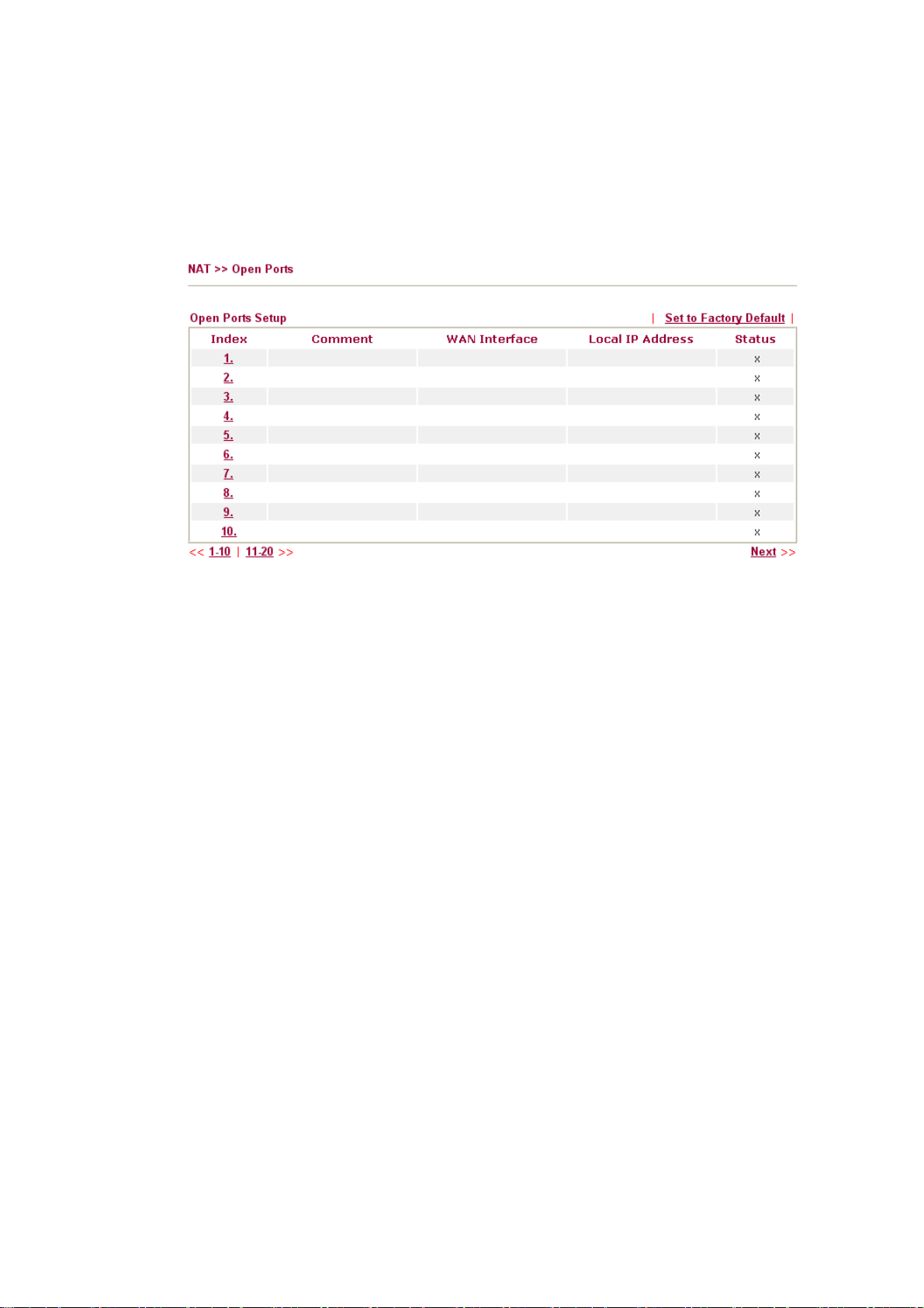
33..33..33 OOppeenn PPoorrttss
Open Ports allows you to open a range of ports for the traffic of special applications. Common application of Open Ports includes P2P application (e.g., BT, KaZaA, Gnutella, WinMX, eMule and others), Internet Camera etc. Ensure that you keep the application involved up-to-date to avoid falling victim to any security exploits.
Click Open Ports to open the following page:
Index Indicate the relative number for the particular entry that you want to
offer service in a local host. You should click the appropriate index
number to edit or clear the corresponding entry.
Comment Specify the name for the defined network service.
WAN Interface Display the WAN interface for the entry.
Local IP Address Display the private IP address of the local host offering the service.
Status Display the state for the corresponding entry. X or V is to represent
the Inactive or Active state.
To add or edit port settings, click one index number on the page. The index entry setup page
will pop up. In each index entry, you can specify 10 port ranges for diverse services.
48
Vigor2950 Series User’s Guide
Page 59
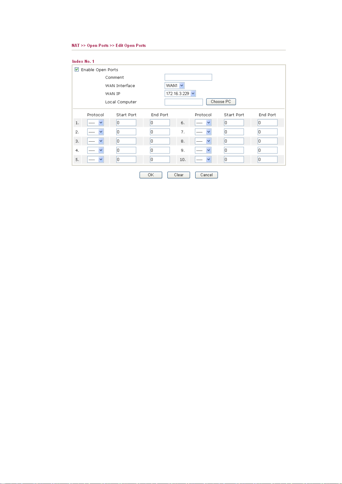
Enable Open Ports Check to enable this entry.
Comment Make a name for the defined network application/service.
WAN Interface Specify the WAN interface that will be used for this entry.
WAN IP Such drop down list will be shown only if you have entered other
WAN IP address in WAN IP Alias window. Choose one of them
to apply open port configuration.
Local Computer Enter the private IP address of the local host or click Choose PC to
select one.
Choose PC Click this button and, subsequently, a window having a list of
private IP addresses of local hosts will automatically pop up. Select
the appropriate IP address of the local host in the list.
Protocol Specify the transport layer protocol. It could be TCP, UDP, or -----
(none) for selection.
Start Port Specify the starting port number of the service offered by the local
host.
End Port Specify the ending port number of the service offered by the local
host.
Vigor2950 Series User’s Guide
49
Page 60

33..33..44 AAddddrreessss MMaappppiinngg
This page is used to map specific private IP to specific WAN IP alias.
If you have "a group of IP Addresses" and want to apply to the router, please use WAN IP
alias function to record these IPs first. Then, use address mapping function to map specific
private IP to specific WAN IP alias.
For example, you have IP addresses ranging from 86.123.123.1 ~ 86.123.123.8. However,
your router uses 86.123.123.1, and the rest of the IPs are recorded in WAN IP alias. You
want that private IP 192.168.1.10 can use 86.123.123.2 as source IP when it sends packet out
to Internet. You can use address mapping function to achieve this demand. Simply type
192.168.1.10 as the Private IP; and type 86.123.123.2 as the WAN IP.
Protocol Display the protocol used for this address mapping.
Public IP Display the public IP address selected for this entry, e.g.,
86.123.123.2.
Private IP Display the private IP set for this address mapping, e.g.,
192.168.1.10
Mask Display the subnet mask selected fro this address mapping.
Status Display the status for the entry, enable or disable.
Click the index number link to open the configuration page.
50
Enable Check to enable this entry.
Vigor2950 Series User’s Guide
Page 61

Protocol Specify the transport layer protocol. It could be TCP, UDP, or
ALL for selection.
WAN Interface Specify the WAN interface that will be used for this entry.
WAN IP Select an IP address (the selections provided here are set in IP
Alias List of Network >>WAN interface). Local host can use this
IP to connect to Internet.
If you want to choose any on of the Public IP settings, you must
specify some IP addresses in the IP Alias List of the Static/DHCP
Configuration page first. If you did not type in any IP address in
the IP Alias List, the Public IP setting will be empty in this field.
When you click Apply, a message will appear to inform you.
Private IP Assign an IP address (e.g., 192.168.1.10) or a subnet to be
compared with the Public IP address for incoming packets.
Subnet Mask Select a value of subnet mask for private IP address.
33..44 FFiirreewwaallll
33..44..11 BBaassiiccss ffoorr FFiirreewwaallll
While the broadband users demand more bandwidth for multimedia, interactive applications,
or distance learning, security has been always the most concerned. The firewall of the Vigor
router helps to protect your local network against attack from unauthorized outsiders. It also
restricts users in the local network from accessing the Internet. Furthermore, it can filter out
specific packets that trigger the router to build an unwanted outgoing connection.
FFiirreewwaallll FFaacciilliittiieess
The users on the LAN are provided with secured protection by the following firewall
facilities:
z User-configurable IP filter (Call Filter/ Data Filter).
z Stateful Packet Inspection (SPI): tracks packets and denies unsolicited incoming data
z Selectable Denial of Service (DoS) /Distributed DoS (DDoS) attacks protection
z URL Content Filter
IIPP FFiilltteerrss
Depending on whether there is an existing Internet connection, or in other words “the WAN
link status is up or down”, the IP filter architecture categorizes traffic into two: Call Filter
and Data Filter.
z Call Filter - When there is no existing Internet connection, Call Filter is applied to all
traffic, all of which should be outgoing. It will check packets according to the filter
rules. If legal, the packet will pass. Then the router shall “initiate a call” to build the
Internet connection and send the packet to Internet.
z Data Filter - When there is an existing Internet connection, Data Filter is applied to
incoming and outgoing traffic. It will check packets according to the filter rules. If legal,
the packet will pass the router.
Vigor2950 Series User’s Guide
51
Page 62

The following illustrations are flow charts explaining how router will treat incoming traffic
and outgoing traffic respectively.
SSttaatteeffuull PPaacckkeett IInnssppeeccttiioonn ((SSPPII))
Stateful inspection is a firewall architecture that works at the network layer. Unlike legacy
static packet filtering, which examines a packet based on the information in its header,
stateful inspection builds up a state machine to track each connection traversing all interfaces
of the firewall and makes sure they are valid. The stateful firewall of Vigor router not just
examine the header information also monitor the state of the connection.
DDeenniiaall ooff SSeerrvviiccee ((DDooSS)) DDeeffeennssee
The DoS Defense functionality helps you to detect and mitigate the DoS attack. The attacks
are usually categorized into two types, the flooding-type attacks and the vulnerability attacks.
The flooding-type attacks will attempt to exhaust all your system's resource while the
vulnerability attacks will try to paralyze the system by offending the vulnerabilities of the
protocol or operation system.
The DoS Defense function enables the Vigor router to inspect every incoming packet based
on the attack signature database. Any malicious packet that might duplicate itself to paralyze
the host in the secure LAN will be strictly blocked and a Syslog message will be sent as
warning, if you set up Syslog server.
Also the Vigor router monitors the traffic. Any abnormal traffic flow violating the pre-defined
parameter, such as the number of thresholds, is identified as an attack and the Vigor router
will activate its defense mechanism to mitigate in a real-time manner.
52
Vigor2950 Series User’s Guide
Page 63
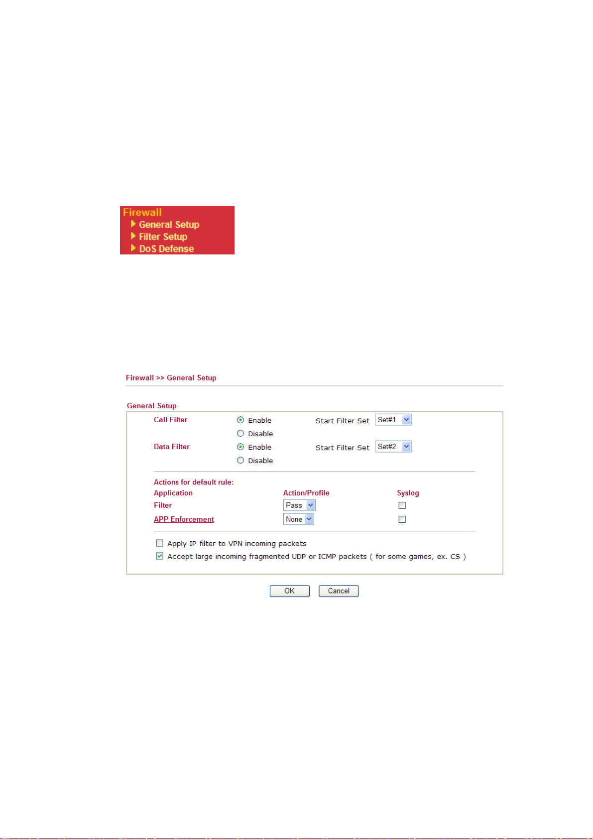
The below shows the attack types that DoS/DDoS defense function can detect:
1. SYN flood attack
2. UDP flood attack
3. ICMP flood attack
4. Port Scan attack
5. IP options
6. Land attack
7. Smurf attack
8. Trace route
Below shows the menu items for Firewall.
33..44..22 GGeenneerraall SSeettuupp
General Setup allows you to adjust settings of IP Filter and common options. Here you can
enable or disable the Call Filter or Data Filter. Under some circumstance, your filter set can
be linked to work in a serial manner. So here you assign the Start Filter Set only. Also you
can configure the Log Flag settings, Apply IP filter to VPN incoming packets, and Accept
incoming fragmented UDP packets.
Click Firewall and click General Setup to open the general setup page.
9. SYN fragment
10. Fraggle attack
11. TCP flag scan
12. Tear drop attack
13. Ping of Death attack
14. ICMP fragment
15. Unknown protocol
Call Filter Check Enable to activate the Call Filter function. Assign a start
Data Filter Check Enable to activate the Data Filter function. Assign a start
Start Filter Set Choose one of the filter sets as the base for call filer/data filter.
Action/Profile Select Pass or Block for the packets that do not match with the
Syslog For troubleshooting needs you can specify the filter log and/ or CSM
Vigor2950 Series User’s Guide
filter set for the Call Filter.
filter set for the Data Filter.
filter rules.
log here by checking the box. The log will be displayed on Draytek
Syslog window.
53
Page 64
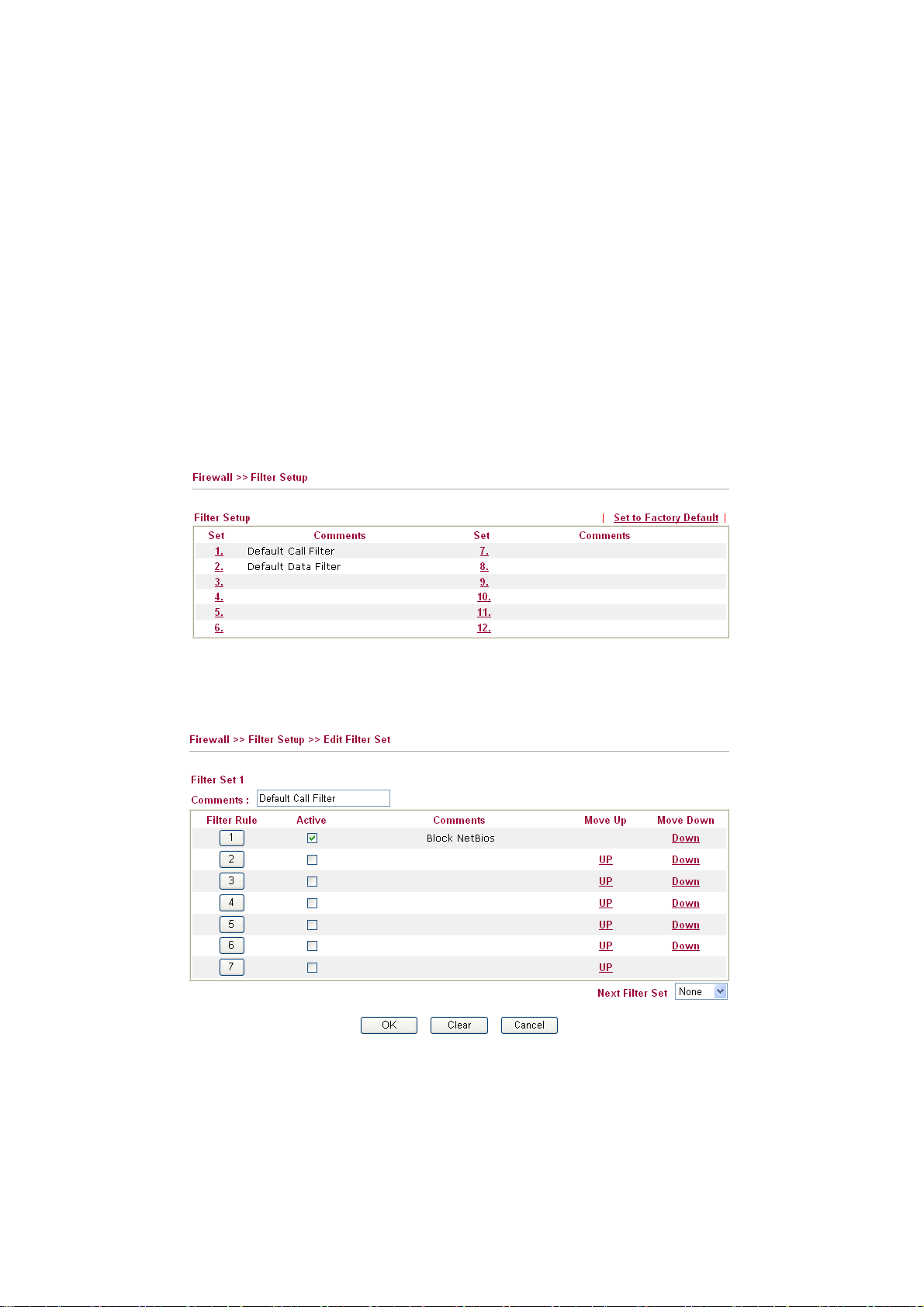
APP Enforcement Select one of the APP Enforcement Profile settings (created in
CSM>> APP Enforcement Profile) for applying with this router.
Please set at least one profile for choosing in CSM>> APP
Enforcement Profile web page first. For troubleshooting needs,
you can specify to record information for APP Enforcement
Profile by checking the Log box. It will be sent to Syslog server.
Please refer to section Syslog/Mail Alert for more detailed
information.
Some on-line games (for example: Half Life) will use lots of fragmented UDP packets to
transfer game data. Instinctively as a secure firewall, Vigor router will reject these
fragmented packets to prevent attack unless you enable “Accept Incoming Fragmented
UDP Packets”. By checking this box, you can play these kinds of on-line games. If security
concern is in higher priority, you cannot enable “Accept Incoming Fragmented UDP
Packets”.
33..44..33 FFiilltteerr SSeettuupp
Click Firewall and click Filter Setup to open the setup page.
To edit or add a filter, click on the set number to edit the individual set. The following page
will be shown. Each filter set contains up to 7 rules. Click on the rule number button to edit
each rule. Check Active to enable the rule.
54
Filter Rule Click a button numbered (1 ~ 7) to edit the filter rule. Click the
button will open Edit Filter Rule web page. For the detailed
information, refer to the following page.
Active Enable or disable the filter rule.
Comment Enter filter set comments/description. Maximum length is
23–character long.
Vigor2950 Series User’s Guide
Page 65

Move Up/Down Use Up or Down link to move the order of the filter rules.
Next Filter Set Set the link to the next filter set to be executed after the current
filter run. Do not make a loop with many filter sets.
To edit Filter Rule, click the Filter Rule index button to enter the Filter Rule setup page.
Check to enable the
Check this box to enable the filter rule.
Filter Rule
Comments Enter filter set comments/description. Maximum length is 14-
character long.
Index(1-15) Set PCs on LAN to work at certain time interval only. You may
choose up to 4 schedules out of the 15 schedules pre-defined in
Applications >> Schedule setup. The default setting of this filed is
blank and the function will always work.
Direction Set the direction of packet flow (LAN->WAN/WAN->LAN). It is
for Data Filter only. For the Call Filter, this setting is not
available since Call Filter is only applied to outgoing traffic.
Source/Destination IP Click Edit to access into the following dialog to choose the
source/destination IP or IP ranges.
Vigor2950 Series User’s Guide
55
Page 66

To set the IP address manually, please choose Any Address/Single
Address/Range Address/Subnet Address as the Address Type
and type them in this dialog. In addition, if you want to use the IP
range from defined groups or objects, please choose Group and
Objects as the Address Type.
From the IP Group drop down list, choose the one that you want
to apply. Or use the IP Object drop down list to choose the object
that you want.
Service Type Click Edit to access into the following dialog to choose a suitable
service type.
To set the service type manually, please choose User defined as
the Service Type and type them in this dialog. In addition, if you
want to use the service type from defined groups or objects, please
56
Vigor2950 Series User’s Guide
Page 67

choose Group and Objects as the Service Type.
Protocol - Specify the protocol(s) which this filter rule will apply to.
Source/Destination Port -
(=) – when the first and last value are the same, it indicates one
port; when the first and last values are different, it indicates a range
for the port and available for this service type.
(!=) – when the first and last value are the same,
it indicates all
the ports except the port defined here; when the first and last
values are different, it indicates that all the ports except the range
defined here are available for this service type.
(>) – the port number greater than this value is available.
(<) – the port number less than this value is available for this
profile.
Service Group/Object - Use the drop down list to choose the one
that you want.
Fragments Specify the action for fragmented packets. And it is used for Data
Filter only.
Don’t care -No action will be taken towards fragmented packets.
Unfragmented -Apply the rule to unfragmented packets.
Fragmented - Apply the rule to fragmented packets.
Too Short - Apply the rule only to packets that are too short to
contain a complete header.
Filter Specifies the action to be taken when packets match the rule.
Block Immediately - Packets matching the rule will be dropped
immediately.
Pass Immediately - Packets matching the rule will be passed
immediately.
Block If No Further Match - A packet matching the rule, and that
does not match further rules, will be dropped.
Pass If No Further Match - A packet matching the rule, and that
does not match further rules, will be passed through.
Branch to other Filter
Set
If the packet matches the filter rule, the next filter rule will branch
to the specified filter set. Select next filter rule to branch from the
drop-down menu. Be aware that the router will apply the
specified filter rule for ever and will not return to previous filter
rule any more.
APP Enforcement
Select one of the APP Enforcement Profile settings (created in
CSM>> APP Enforcement Profile) for applying with this router.
Please set at least one profile for choosing in CSM>> APP
Enforcement Profile web page first. For troubleshooting needs,
you can specify to record information for APP Enforcement
Profile by checking the Log box. It will be sent to Syslog server.
Please refer to section Syslog/Mail Alert for more detailed
information.
SysLog For troubleshooting needs you can specify the filter log and/or CSM
Vigor2950 Series User’s Guide
log here. Check the corresponding box to enable the log function.
Then, the filter log and/or CSM log will be shown on Draytek
Syslog window.
57
Page 68

EExxaammppllee
As stated before, all the traffic will be separated and arbitrated using on of two IP filters: call
filter or data filter. You may preset 12 call filters and data filters in Filter Setup and even
link them in a serial manner. Each filter set is composed by 7 filter rules, which can be
further defined. After that, in General Setup you may specify one set for call filter and one
set for data filter to execute first.
58
Vigor2950 Series User’s Guide
Page 69

33..44..44 DDooSS DDeeffeennssee
As a sub-functionality of IP Filter/Firewall, there are 15 types of detect/ defense function in the DoS Defense setup. The DoS Defense functionality is disabled for default.
Click Firewall and click DoS Defense to open the setup page.
Enable Dos Defense Check the box to activate the DoS Defense Functionality.
Enable SYN flood
defense
Check the box to activate the SYN flood defense function. Once
detecting the Threshold of the TCP SYN packets from the
Internet has exceeded the defined value, the Vigor router will start
to randomly discard the subsequent TCP SYN packets for a
period defined in Timeout. The goal for this is prevent the TCP
SYN packets’ attempt to exhaust the limited-resource of Vigor
router. By default, the threshold and timeout values are set to 50
packets per second and 10 seconds, respectively.
Enable UDP flood
defense
Check the box to activate the UDP flood defense function. Once
detecting the Threshold of the UDP packets from the Internet has
exceeded the defined value, the Vigor router will start to
randomly discard the subsequent UDP packets for a period
defined in Timeout. The default setting for threshold and timeout
are 150 packets per second and 10 seconds, respectively.
Enable ICMP flood
defense
Check the box to activate the ICMP flood defense function.
Similar to the UDP flood defense function, once if the Threshold
of ICMP packets from Internet has exceeded the defined value, the
router will discard the ICMP echo requests coming from the
Internet. The default setting for threshold and timeout are 50
packets per second and 10 seconds, respectively.
Enable PortScan
detection
Vigor2950 Series User’s Guide
Port Scan attacks the Vigor router by sending lots of packets to
many ports in an attempt to find ignorant services would respond.
Check the box to activate the Port Scan detection. Whenever
detecting this malicious exploration behavior by monitoring the
59
Page 70

port-scanning Threshold rate, the Vigor router will send out a
warning. By default, the Vigor router sets the threshold as 150
packets per second.
Block IP options Check the box to activate the Block IP options function. The Vigor
router will ignore any IP packets with IP option field in the
datagram header. The reason for limitation is IP option appears to
be a vulnerability of the security for the LAN because it will carry
significant information, such as security, TCC (closed user group)
parameters, a series of Internet addresses, routing messages...etc.
An eavesdropper outside might learn the details of your private
networks.
Block Land
Check the box to enforce the Vigor router to defense the Land
attacks. The Land attack combines the SYN attack technology with
IP spoofing. A Land attack occurs when an attacker sends spoofed
SYN packets with the identical source and destination addresses,
as well as the port number to victims.
Block Smurf Check the box to activate the Block Smurf function. The Vigor
router will ignore any broadcasting ICMP echo request.
Block trace router Check the box to enforce the Vigor router not to forward any trace
route packets.
Block SYN fragment Check the box to activate the Block SYN fragment function. The
Vigor router will drop any packets having SYN flag and more
fragment bit set.
Block Fraggle Attack Check the box to activate the Block fraggle Attack function. Any
broadcast UDP packets received from the Internet is blocked.
Activating the DoS/DDoS defense functionality might block some
legal packets. For example, when you activate the fraggle attack
defense, all broadcast UDP packets coming from the Internet are
blocked. Therefore, the RIP packets from the Internet might be
dropped.
Block TCP flag scan Check the box to activate the Block TCP flag scan function. Any
TCP packet with anomaly flag setting is dropped. Those scanning
activities include no flag scan, FIN without ACK scan, SYN FINscan,
Xmas scan and full Xmas scan.
60
Block Tear Drop Check the box to activate the Block Tear Drop function. Many
machines may crash when receiving ICMP datagrams (packets) that
exceed the maximum length. To avoid this type of attack, the Vigor
router is designed to be capable of discarding any fragmented ICMP
packets with a length greater than 1024 octets.
Block Ping of Death Check the box to activate the Block Ping of Death function. This
attack involves the perpetrator sending overlapping packets to the
target hosts so that those target hosts will hang once they
re-construct the packets. The Vigor routers will block any packets
realizing this attacking activity.
Block ICMP Fragment Check the box to activate the Block ICMP fragment function. Any
ICMP packets with more fragment bit set are dropped.
Block Land
Check the box to enforce the Vigor router to defense the Land
attacks. The Land attack combines the SYN attack technology with
IP spoofing. A Land attack occurs when an attacker sends spoofed
Vigor2950 Series User’s Guide
Page 71

SYN packets with the identical source and destination addresses,
as well as the port number to victims.
Block Unknown
Protocol
Check the box to activate the Block Unknown Protocol function.
Individual IP packet has a protocol field in the datagram header to
indicate the protocol type running over the upper layer. However,
the protocol types greater than 100 are reserved and undefined at
this time. Therefore, the router should have ability to detect and
reject this kind of packets.
Warning Messages We provide Syslog function for user to retrieve message from Vigor
router. The user, as a Syslog Server, shall receive the report sending
from Vigor router which is a Syslog Client.
All the warning messages related to DoS defense will be sent to user
and user can review it through Syslog daemon. Look for the
keyword DoS in the message, followed by a name to indicate what
kind of attacks is detected.
Vigor2950 Series User’s Guide
61
Page 72

33..55 OObbjjeeccttss SSeettttiinnggss
For IPs in a range and service ports in a limited range usually will be applied in configuring
router’s settings, therefore we can define them with objects and bind them with groups for
using conveniently. Later, we can select that object/group that can apply it. For example, all
the IPs in the same department can be defined with an IP object (a range of IP address).
33..55..11 IIPP OObbjjeecctt
You can set up to 192 sets of IP Objects with different conditions.
62
Set to Factory Default Clear all profiles.
Click the number under Index column for settings in detail.
Vigor2950 Series User’s Guide
Page 73

Name Type a name for this profile. Maximum 15 characters are
allowed.
Interface Choose a proper interface (WAN, LAN or Any).
For example, the Direction setting in Edit Filter Rule will
ask you specify IP or IP range for WAN or LAN or any IP
address. If you choose LAN as the Interface here, and choose
LAN as the direction setting in Edit Filter Rule, then all the
IP addresses specified with LAN interface will be opened for
you to choose in Edit Filter Rule page.
Address Type Determine the address type for the IP address.
Select Single Address if this object contains one IP address
only.
Select Range Address if this object contains several IPs
within a range.
Select Subnet Address if this object contains one subnet for
IP address.
Select Any Address if this object contains any IP address.
Start IP Address Type the start IP address for Single Address type.
End IP Address Type the end IP address if the Range Address type is selected.
Subnet Mask Type the subnet mask if the Subnet Address type is selected.
Invert Select If it is checked, all the IP addresses except the ones listed
above will be applied later while it is chosen.
Below is an example of IP objects settings.
Vigor2950 Series User’s Guide
63
Page 74
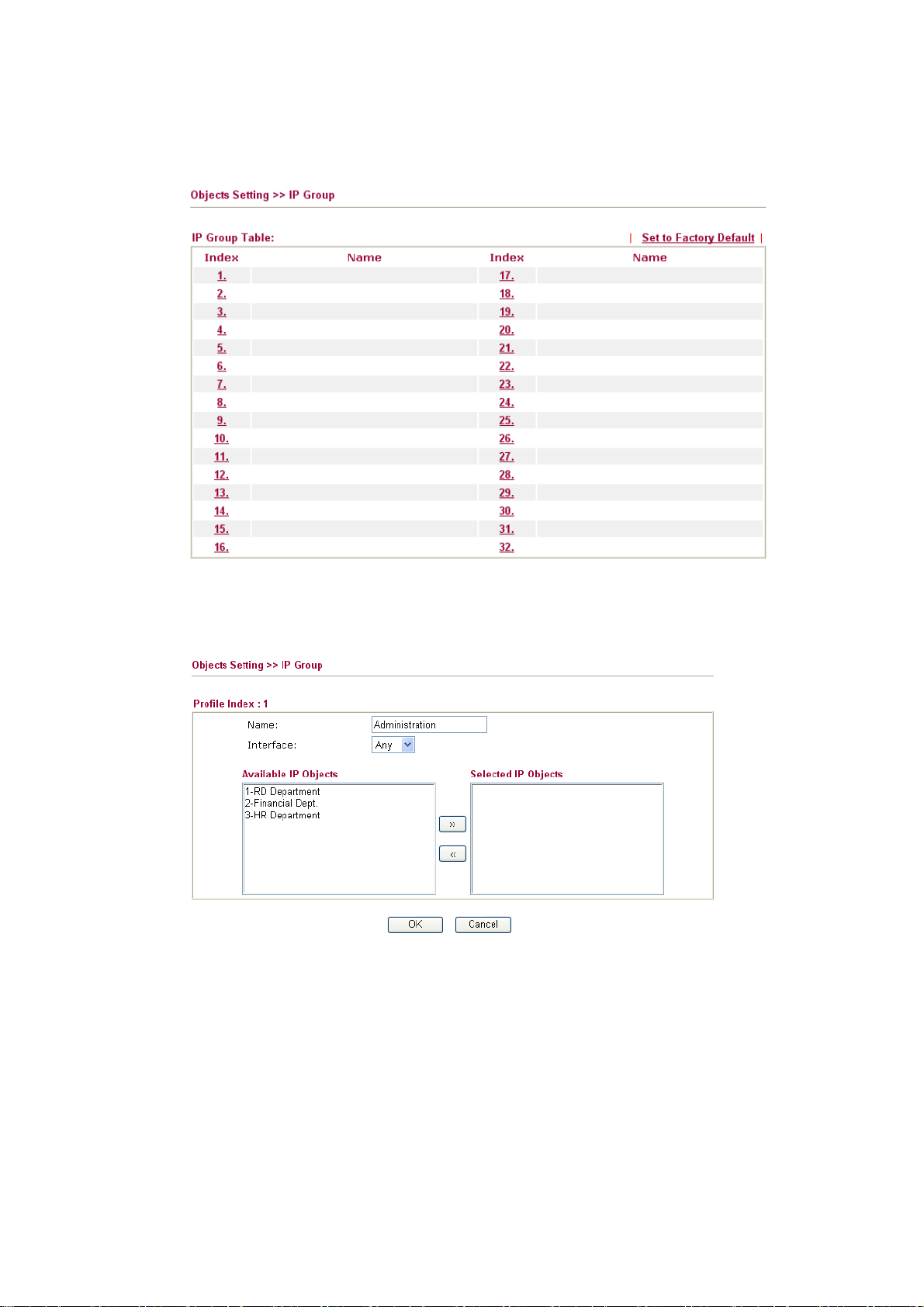
33..55..22 IIPP GGrroouupp
This page allows you to bind several IP objects into one IP group.
Set to Factory Default Clear all profiles.
Click the number under Index column for settings in detail.
Name Type a name for this profile. Maximum 15 characters are
allowed.
Interface Choose WAN, LAN or Any to display all the available IP
objects with the specified interface.
Available IP Objects All the available IP objects with the specified interface chosen
above will be shown in this box.
64
Selected IP Objects Click >> button to add the selected IP objects in this box.
Vigor2950 Series User’s Guide
Page 75
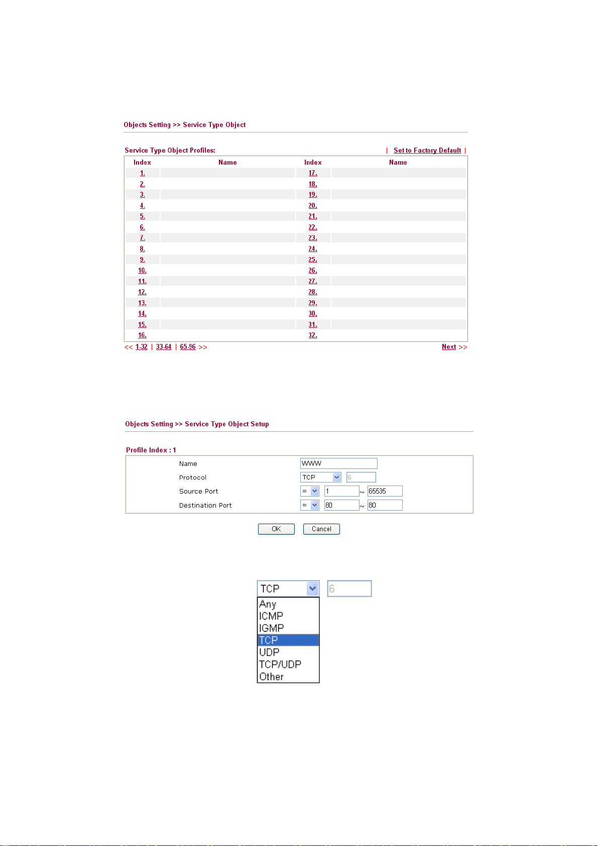
33..55..33 SSeerrvviiccee TTyyppee OObbjjeecctt
You can set up to 96 sets of Service Type Objects with different conditions.
Set to Factory Default Clear all profiles.
Click the number under Index column for settings in detail.
Name Type a name for this profile.
Protocol Specify the protocol(s) which this profile will apply to.
Source/Destination Port Source Port and the Destination Port column are available
Vigor2950 Series User’s Guide
for TCP/UDP protocol. It can be ignored for other protocols.
The filter rule will filter out any port number.
(=) – when the first and last value are the same, it indicates
one port; when the first and last values are different, it
indicates a range for the port and available for this profile.
65
Page 76

(!=) – when the first and last value are the same, it indicates
all the ports except the port defined here; when the first
and last values are different, it indicates that all the ports
except the range defined here are available for this service
type.
(>) – the port number greater than this value is available.
(<) – the port number less than this value is available for this
profile.
Below is an example of service type objects settings.
33..55..44 SSeerrvviiccee TTyyppee GGrroouupp
This page allows you to bind several service types into one group.
Set to Factory Default Clear all profiles.
66
Click the number under Index column for settings in detail.
Vigor2950 Series User’s Guide
Page 77
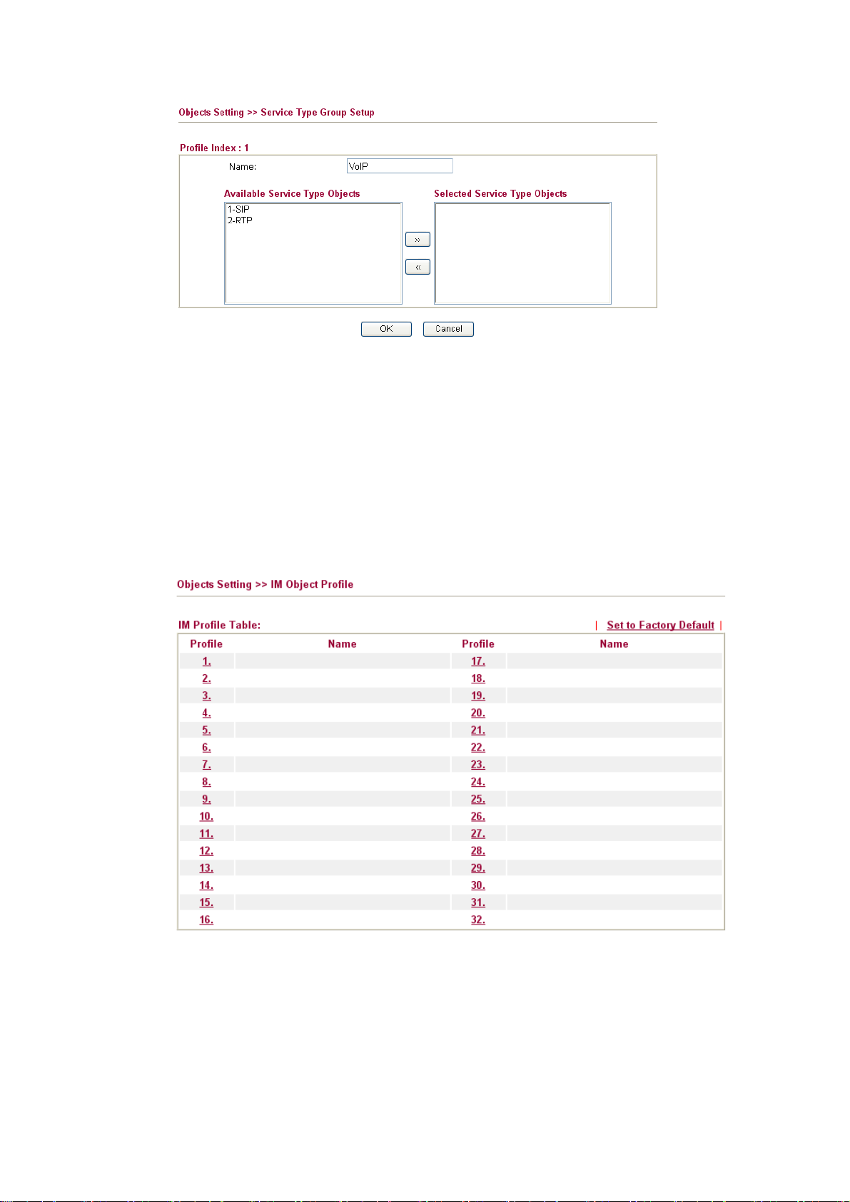
Name Type a name for this profile.
Available Service Type
Objects
Selected Service Type
Objects
33..55..55 IIMM OObbjjeecctt
This page allows you to set 32 profiles for Instant Messenger. These profiles will be applied
in CSM>>APP Enforcement Profile for filtering.
You can add IP objects from IP Objects page. All the
available IP objects will be shown in this box.
Click >> button to add the selected IP objects in this box.
Set to Factory Default Clear all profiles.
Click the number under Profile column for configuration in details. There are several types
of Instant Messenger (IM) provided here for you to choose to disallow people using. Simple check the box (es) and then click OK. Later, in the CSM>>APP Enforcement Profile page, you can use IM Object drop down list to choose the proper profile configured here as the standard for the host(s) to follow.
Vigor2950 Series User’s Guide
67
Page 78
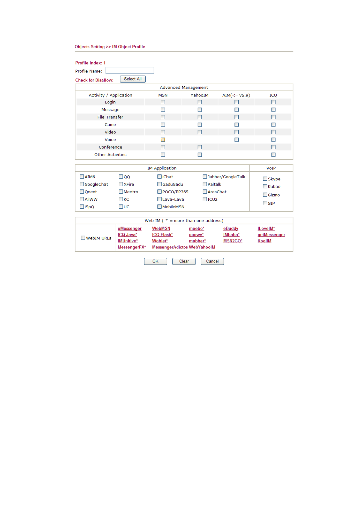
Profile Name Type a name for this profile.
Type a name for such profile and check all the items that not allowed to be used in the host.
Finally, click OK to save this profile.
68
Vigor2950 Series User’s Guide
Page 79
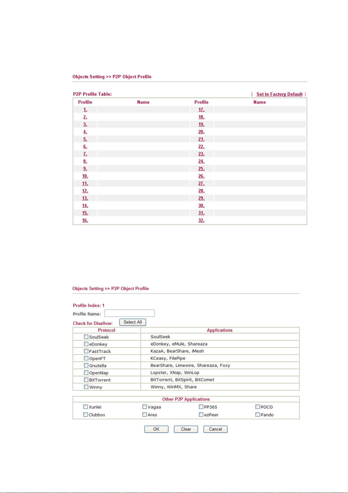
33..55..66 PP22PP OObbjjeecctt
This page allows you to set 32 profiles for peer-to-peer application. These profiles will be
applied in CSM>>APP Enforcement Profile for filtering.
Set to Factory Default Clear all profiles.
Click the number under Profile column for configuration in details. There are several items
for P2P protocols provided here for you to choose to disallow people using. Simple check the box (es) and then click OK. Later, in the CSM>>APP Enforcement Profile page, you can use P2P Object drop down list to choose the proper profile configured here as the standard for the host(s) to follow.
Profile Name Type a name for this profile.
Vigor2950 Series User’s Guide
69
Page 80

Type a name for such profile and check all the protocols that not allowed to be used in the
host. Finally, click OK to save this profile.
33..55..77 PPrroottooccooll OObbjjeecctt
This page allows you to set 32 profiles for applications in protocol communication. These
profiles will be applied in CSM>>APP Enforcement Profile for filtering.
Set to Factory Default Clear all profiles.
Click the number under Profile column for configuration in details. Internet protocols are
listed in the page for you to choose to disallow people using. Any computer controlled or
passed through the router will be restricted by this profile if it tries to use the protocol to
communicate with others.
Simple check the box(es) and then click OK. Later, in the CSM>>APP Enforcement Profile page, you can use Protocol Object drop down list to choose the proper profile configured here as the standard for the host(s) to follow.
Profile Name Type a name for this profile.
70
Type a name for such profile and check all the protocols that not allowed to be used in the
host. Finally, click OK to save this profile.
Vigor2950 Series User’s Guide
Page 81

33..55..88 MMiisscc OObbjjeecctt
This page allows you to set 32 profiles for miscellaneous applications. These profiles will be
applied in CSM>> APP Enforcement Profile for filtering.
Set to Factory Default Clear all profiles.
Click the number under Profile column for configuration in details. Applications for
tunneling and streaming are listed in the page for you to choose to disallow people using. Simple check the box (es) and then click OK. Later, in the CSM>>APP Enforcement Profile page, you can use Misc Object drop down list to choose the proper profile configured here as the standard for the host(s) to follow.
Vigor2950 Series User’s Guide
71
Page 82

Profile Name Type a name for this profile.
Type a name for such profile and check all the protocols that not allowed to be used in the
host. Finally, click OK to save this profile.
33..66 CCSSMM
CSM is an abbreviation of Content Security Management which is used to control IM/P2P usage, filter the web content and URL content to reach a goal of security management.
IIMM//PP22PP FFiilltteerr
As the popularity of all kinds of instant messenger application arises, communication cannot
become much easier. Nevertheless, while some industry may leverage this as a great tool to
connect with their customers, some industry may take reserve attitude in order to reduce
employee misusage during office hour or prevent unknown security leak. It is similar
situation for corporation towards peer-to-peer applications since file-sharing can be
convenient but insecure at the same time. To address these needs, we provide CSM
functionality.
UURRLL CCoonntteenntt FFiilltteerr
To provide an appropriate cyberspace to users, Vigor router equips with URL Content Filter
not only to limit illegal traffic from/to the inappropriate web sites but also prohibit other web
feature where malicious code may conceal.
72
Once a user type in or click on an URL with objectionable keywords, URL keyword blocking
facility will decline the HTTP request to that web page thus can limit user’s access to the
website. You may imagine URL Content Filter as a well-trained convenience-store clerk
who won’t sell adult magazines to teenagers. At office, URL Content Filter can also provide
a job-related only environment hence to increase the employee work efficiency. How can
URL Content Filter work better than traditional firewall in the field of filtering? Because it
Vigor2950 Series User’s Guide
Page 83

checks the URL strings or some of HTTP data hiding in the payload of TCP packets while
legacy firewall inspects packets based on the fields of TCP/IP headers only.
On the other hand, Vigor router can prevent user from accidentally downloading malicious
codes from web pages. It’s very common that malicious codes conceal in the executable
objects, such as ActiveX, Java Applet, compressed files, and other executable files. Once
downloading these types of files from websites, you may risk bringing threat to your system.
For example, an ActiveX control object is usually used for providing interactive web feature.
If malicious code hides inside, it may occupy user’s system.
For example, if you add key words such as “sex”, Vigor router will limit web access to web
sites or web pages such as “www.sex.com”, ”www.backdoor.net/images/sex/p_386.html”.
Or you may simply specify the full or partial URL such as “www.sex.com” or “sex.com”.
Also the Vigor router will discard any request that tries to retrieve the malicious code.
WWeebb CCoonntteenntt FFiilltteerr
We all know that the content on the Internet just like other types of media may be
inappropriate sometimes. As a responsible parent or employer, you should protect those in
your trust against the hazards. With Web filtering service of the Vigor router, you can protect
your business from common primary threats, such as productivity, legal liability, network and
security threats. For parents, you can protect your children from viewing adult websites or
chat rooms.
Once you have activated your Web Filtering service in Vigor router and chosen the categories
of website you wish to restrict, each URL address requested (e.g.www.bbc.co.uk) will be
checked against our server database. This database is updated as frequent as daily by a global
team of Internet researchers. The server will look up the URL and return a category to your
router. Your Vigor router will then decide whether to allow access to this site according to the
categories you have selected. Please note that this action will not introduce any delay in your
Web surfing because each of multiple load balanced database servers can handle millions of
requests for categorization.
Note: The priority of URL Content Filter is higher than Web Content Filter.
Vigor2950 Series User’s Guide
73
Page 84

33..66..11 AAPPPP EEnnffoorrcceemmeenntt PPrrooffiillee
You can define policy profiles for different policy of IM (Instant Messenger)/P2P (Peer to
Peer) application. Such profile will be used in Firewall>>General Setup and
Firewall>>Filter Setup pages.
Set to Factory Default Clear all profiles.
Click the number under Index column for settings in detail.
Profile Name Type a name for the CSM profile.
Each profile can contain three objects settings, IM Object, P2P Object and Misc Object.
Such profile can be applied in the Firewall>>General Setup and Firewall>>Filter Setup
pages as the standard for the host(s) to follow.
74
Vigor2950 Series User’s Guide
Page 85

33..66..22 UURRLL CCoonntteenntt FFiilltteerr PPrrooffiillee
Click CSM and click URL Content Filter Profile to open the profile setting page.
Enable URL Access
Check the box to activate URL Access Control.
Control
Black List (block those
matching keyword)
White List (pass those
matching keyword)
Click this button to restrict accessing into the corresponding
webpage with the keywords listed on the box below.
Click this button to allow accessing into the corresponding
webpage with the keywords listed on the box below.
Keyword The Vigor router provides 8 frames for users to define keywords
and each frame supports multiple keywords. The keyword could be
a noun, a partial noun, or a complete URL string. Multiple
keywords within a frame are separated by space, comma, or
semicolon. In addition, the maximal length of each frame is
32-character long. After specifying keywords, the Vigor router will
decline the connection request to the website whose URL string
matched to any user-defined keyword. It should be noticed that the
more simplified the blocking keyword list, the more efficiently the
Vigor router perform.
Prevent web access
from IP address
Check the box to deny any web surfing activity using IP address,
such as http://202.6.3.2. The reason for this is to prevent someone
dodges the URL Access Control.
Vigor2950 Series User’s Guide
75
Page 86

You must clear your browser cache first so that the URL content
filtering facility operates properly on a web page that you visited
before.
Enable Restrict Web
Feature
Check the box to activate the function.
Java - Check the checkbox to activate the Block Java object
function. The Vigor router will discard the Java objects from the
Internet.
ActiveX - Check the box to activate the Block ActiveX object
function. Any ActiveX object from the Internet will be refused.
Compressed file - Check the box to activate the Block Compressed
file function to prevent someone from downloading any
compressed file. The following list shows the types of compressed
files that can be blocked by the Vigor router. .
zip, rar, .arj, .ace, .cab, .sit
Executable file - Check the box to reject any downloading
behavior of the executable file from the Internet.
.exe, .com, .scr, .pif, .bas, .bat, .inf, .reg
Cookie - Check the box to filter out the cookie transmission from
inside to outside world to protect the local user's privacy.
Proxy - Check the box to reject any proxy transmission. To control
efficiently the limited-bandwidth usage, it will be of great value to
provide the blocking mechanism that filters out the multimedia
files downloading from web pages. Accordingly, files with the
following extensions will be blocked by the Vigor router.
.mov .mp3 .rm .ra .au .wmv
.wav .asf .mpg .mpeg .avi .ram
Enable Excepting
Subnets
Four entries are available for users to specify some specific IP
addresses or subnets so that they can be free from the URL Access
Control. To enable an entry, click on the empty checkbox, named
as ACT, in front of the appropriate entry.
Time Schedule Specify what time should perform the URL content filtering facility.
76
Vigor2950 Series User’s Guide
Page 87

33..66..33 WWeebb CCoonntteenntt FFiilltteerr PPrrooffiillee
We all know that the content on the Internet just like other types of media may be
inappropriate sometimes. As a responsible parent or employer, you should protect those in
your trust against the hazards. With Web filtering service of the Vigor router, you can protect
your business from common primary threats, such as productivity, legal liability, network and
security threats. For parents, you can protect your children from viewing adult websites or
chat rooms.
Once you have activated your Web Filtering service in Vigor router and chosen the categories
of website you wish to restrict, each URL address requested (e.g.www.bbc.co.uk) will be
checked against our server database. This database is updated as frequent as daily by a global
team of Internet researchers. The server will look up the URL and return a category to your
router. Your Vigor router will then decide whether to allow access to this site according to the
categories you have selected. Please note that this action will not introduce any delay in your
Web surfing because each of multiple load balanced database servers can handle millions of
requests for categorization.
Click CSM and click Web Content Filter Profile to open the profile setting page.
For this section, please refer to Web Content Filter user’s guide.
Vigor2950 Series User’s Guide
77
Page 88

33..77 BBaannddwwiiddtthh MMaannaaggeemmeenntt
Below shows the menu items for Bandwidth Management.
33..77..11 SSeessssiioonnss LLiimmiitt
A PC with private IP address can access to the Internet via NAT router. The router will
generate the records of NAT sessions for such connection. The P2P (Peer to Peer)
applications (e.g., BitTorrent) always need many sessions for procession and also they will
occupy over resources which might result in important accesses impacted. To solve the
problem, you can use limit session to limit the session procession for specified Hosts.
In the Bandwidth Management menu, click Sessions Limit to open the web page.
78
To activate the function of limit session, simply click Enable and set the default session
limit.
Enable Click this button to activate the function of limit session.
Disable Click this button to close the function of limit session.
Default session limit Defines the default session number used for each computer in
LAN.
Limitation List Display a list of specific limitations that you set on this web
page.
Start IP Defines the start IP address for limit session.
End IP Defines the end IP address for limit session.
Vigor2950 Series User’s Guide
Page 89

Maximum Sessions Defines the available session number for each host in the
specific range of IP addresses. If you do not set the session
number in this field, the system will use the default session
limit for the specific limitation you set for each index.
Add Adds the specific session limitation onto the list above.
Edit Allows you to edit the settings for the selected limitation.
Delete Remove the selected settings existing on the limitation list.
Index (1-15) in Schedule
Setup
33..77..22 BBaannddwwiiddtthh LLiimmiitt
The downstream or upstream from FTP, HTTP or some P2P applications will occupy large
of bandwidth and affect the applications for other programs. Please use Limit Bandwidth to
make the bandwidth usage more efficient.
In the Bandwidth Management menu, click Bandwidth Limit to open the web page.
You can type in four sets of time schedule for your request.
All the schedules can be set previously in Application –
Schedule web page and you can use the number that you
have set in that web page.
To activate the function of limit bandwidth, simply click Enable and set the default upstream
and downstream limit.
Enable Click this button to activate the function of limit bandwidth.
Disable Click this button to close the function of limit bandwidth.
Vigor2950 Series User’s Guide
nd
Apply to 2
Subnet – Check this box to apply the
bandwidth limit to the second subnet specified in
LAN>>General Setup.
79
Page 90

Default TX limit Define the default speed of the upstream for each computer in
LAN.
Default RX limit Define the default speed of the downstream for each computer
in LAN.
Allow auto adjustment to
make the best utilization
of available bandwidth
Router will detect if there is enough bandwidth remained for
using according to the bandwidth limit set by the user. If yes,
the router will adjust the available bandwidth for users to
enhance the total utilization.
Limitation List Display a list of specific limitations that you set on this web
page.
Start IP Bandwidth limit can be applied on certain IP range. That’s,
only the PCs within the range will be influenced by the
bandwidth limitation set here. Please define the start IP
address for the specific limitation.
End IP Define the end IP address for the specific limitation.
Each /Shared Click the radio button to determine the specific limitation will
be applied to.
Each – The bandwidth limit for transmission and receiving
(TX limit and RX limit) will be applied to each PC on certain
IP range.
Shared - The bandwidth limit for transmission and receiving
(TX limit and RX limit) will be shared by all of the PCs on
certain IP range.
TX limit Define the limitation for the speed of the upstream to be
applied as specific limitation. If you do not set the limit in this
field, the system will use the default speed for the specific
limitation you set for each index.
RX limit Define the limitation for the speed of the downstream to be
Add Add the specific speed limitation onto the list above.
Edit Allows you to edit the settings for the selected limitation.
Delete Remove the selected settings existing on the limitation list.
Index (1-15) in Schedule
Setup
33..77..33 QQuuaalliittyy ooff SSeerrvviiccee
Deploying QoS (Quality of Service) management to guarantee that all applications receive
the service levels required and sufficient bandwidth to meet performance expectations is
indeed one important aspect of modern enterprise network.
One reason for QoS is that numerous TCP-based applications tend to continually increase
their transmission rate and consume all available bandwidth, which is called TCP slow start.
If other applications are not protected by QoS, it will detract much from their performance in
applied as specific limitation. If you do not set the limit in this
field, the system will use the default speed for the specific
limitation you set for each index.
You can type in four sets of time schedule for your request.
All the schedules can be set previously in Application –
Schedule web page and you can use the number that you have
set in that web page.
80
Vigor2950 Series User’s Guide
Page 91

the overcrowded network. This is especially essential to those are low tolerant of loss, delay
or jitter (delay variation).
Another reason is due to congestions at network intersections where speeds of
interconnected circuits mismatch or traffic aggregates, packets will queue up and traffic can
be throttled back to a lower speed. If there’s no defined priority to specify which packets
should be discarded (or in another term “dropped”) from an overflowing queue, packets of
sensitive applications mentioned above might be the ones to drop off. How this will affect
application performance?
There are two components within Primary configuration of QoS deployment:
z Classification: Identifying low-latency or crucial applications and marking them for
high-priority service level enforcement throughout the network.
z Scheduling: Based on classification of service level to assign packets to queues and
associated service types
The basic QoS implementation in Vigor routers is to classify and schedule packets based on
the service type information in the IP header. For instance, to ensure the connection with the
headquarter, a teleworker may enforce an index of QoS Control to reserve bandwidth for
HTTPS connection while using lots of application at the same time.
One more larger-scale implementation of QoS network is to apply DSCP (Differentiated
Service Code Point) and IP Precedence disciplines at Layer 3. Compared with legacy IP
Precedence that uses Type of Service (ToS) field in the IP header to define 8 service classes,
DSCP is a successor creating 64 classes possible with backward IP Precedence compatibility.
In a QoS-enabled network, or Differentiated Service (DiffServ or DS) framework, a DS
domain owner should sign a Service License Agreement (SLA) with other DS domain
owners to define the service level provided toward traffic from different domains. Then each
DS node in these domains will perform the priority treatment. This is called
per-hop-behavior (PHB). The definition of PHB includes Expedited Forwarding (EF),
Assured Forwarding (AF), and Best Effort (BE). AF defines the four classes of delivery (or
forwarding) classes and three levels of drop precedence in each class.
Vigor routers as edge routers of DS domain shall check the marked DSCP value in the IP
header of bypassing traffic, thus to allocate certain amount of resource execute appropriate
policing, classification or scheduling. The core routers in the backbone will do the same
checking before executing treatments in order to ensure service-level consistency throughout
the whole QoS-enabled network.
However, each node may take different attitude toward packets with high priority marking
since it may bind with the business deal of SLA among different DS domain owners. It’s not
easy to achieve deterministic and consistent high-priority QoS traffic throughout the whole
network with merely Vigor router’s effort.
In the Bandwidth Management menu, click Quality of Service to open the web page.
Vigor2950 Series User’s Guide
81
Page 92

This page displays the QoS settings result of the WAN interface. Click the Setup link to
access into next page for the general setup of WAN (1/2) interface. As to class rule, simply
click the Edit link to access into next for configuration.
You can configure general setup for the WAN interface, edit the Class Rule, and edit the
Service Type for the Class Rule for your request.
GGeenneerraall SSeettuupp ffoorr WWAANN IInntteerrffaaccee
When you click Setup, you can configure the bandwidth ratio for QoS of the WAN interface.
There are four queues allowed for QoS control. The first three (Class 1 to Class 3) class rules
can be adjusted for your necessity. Yet, the last one is reserved for the packets which are not
suitable for the user-defined class rules.
82
Enable the QoS Control The factory default for this setting is checked.
Please also define which traffic the QoS Control settings will
apply to.
IN- apply to incoming traffic only.
OUT-apply to outgoing traffic only.
BOTH- apply to both incoming and outgoing traffic.
Vigor2950 Series User’s Guide
Page 93
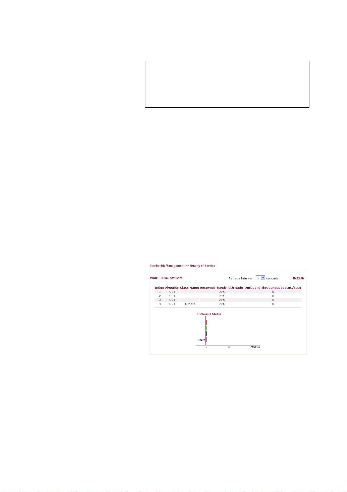
Check this box and click OK, then click Setup link again.
You will see the Online Statistics link appearing on this page.
Note: Before enable QoS control, you should test the real
bandwidth first. QoS may not work properly if the
bandwidth is not accurate. You can visit
www.speedtest.net or contact with your ISP to get speed
test page. Type proper inbound/outbond bandwidth value
according to the value obtained from the speed test results.
WAN Inbound Bandwidth It allows you to set the connecting rate of data input for WAN.
For example, if your ADSL supports 1M of downstream and
256K upstream, please set 10000kbps for this box. The default
value is 10000kbps.
WAN Outbound Bandwidth It allows you to set the connecting rate of data output for
WAN. For example, if your ADSL supports 1M of
downstream and 256K upstream, please set 256kbps for this
Reserved Bandwidth Ratio It is reserved for the group index in the form of ratio of
reserved bandwidth to upstream speed and reserved
bandwidth to downstream speed.
Enable UDP Bandwidth
Control
Check this and set the limited bandwidth ratio on the right
field. This is a protection of TCP application traffic since
UDP application traffic such as streaming video will exhaust
lots of bandwidth.
Limited_bandwidth Ratio The ratio typed here is reserved for limited bandwidth of UDP
application.
On Line Statistics Display an online statistics for quality of service for your
reference.
Such function is available only after QoS Control is enabled
and access Setup link from Quality of Service page again.
EEddiitt tthhee CCllaassss RRuullee ffoorr QQooSS
The first three (Class 1 to Class 3) class rules can be adjusted for your necessity. To add, edit
or delete the class rule, please click the Edit link of that one.
Vigor2950 Series User’s Guide
83
Page 94
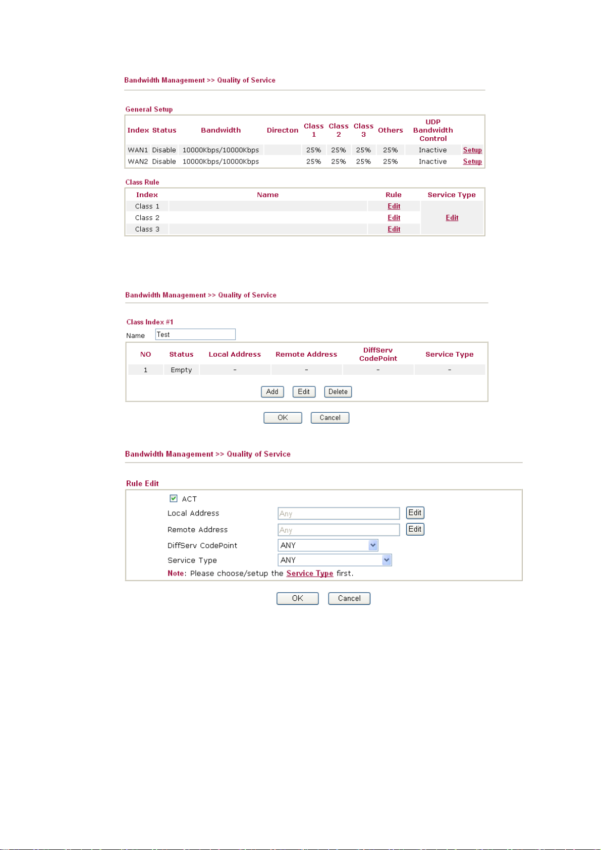
After you click the Edit link, you will see the following page. Now you can define the name
for that Class. In this case, “Test” is used as the name of Class Index #1.
For adding a new rule, click Add to open the following page.
ACT Check this box to invoke these settings.
Local Address Click the Edit button to set the local IP address (on LAN) for
the rule.
Remote Address Click the Edit button to set the remote IP address (on
LAN/WAN) for the rule.
84
Vigor2950 Series User’s Guide
Page 95
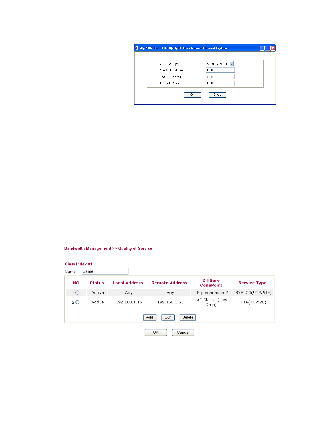
Edit It allows you to edit source address information.
Address Type – Determine the address type for the source
address.
For Single Address, you have to fill in Start IP address.
For Range Address, you have to fill in Start IP address and
End IP address.
For Subnet Address, you have to fill in Start IP address and
Subnet Mask.
DiffServ CodePoint All the packets of data will be divided with different levels
and will be processed according to the level type by the
system. Please assign one of the level of the data for
processing with QoS control.
Service Type It determines the service type of the data for processing with
QoS control. It can also be edited. You can choose the
predefined service type from the Service Type drop down list.
Those types are predefined in factory. Simply choose the one
that you want for using by current QoS.
By the way, you can set up to 20 rules for one Class. If you want to edit an existed rule,
please select the radio button of that one and click Edit to open the rule edit page for
modification.
EEddiitt tthhee SSeerrvviiccee TTyyppee ffoorr CCllaassss RRuullee
To add a new service type, edit or delete an existed service type, please click the Edit link
under Service Type field.
Vigor2950 Series User’s Guide
85
Page 96

After you click the Edit link, you will see the following page.
For adding a new service type, click Add to open the following page.
Service Name Type in a new service for your request.
Service Type Choose the type (TCP, UDP or TCP/UDP) for the new
service.
Port Configuration Click Single or Range. If you select Range, you have to type
in the starting port number and the end porting number on the
boxes below.
Port Number – Type in the starting port number and the end
porting number here if you choose Range as the type.
86
By the way, you can set up to 40 service types. If you want to edit/delete an existed service
type, please select the radio button of that one and click Edit/Edit for modification.
Vigor2950 Series User’s Guide
Page 97

33..88 AApppplliiccaattiioonnss
Below shows the menu items for Applications.
33..88..11 DDyynnaammiicc DDNNSS
The ISP often provides you with a dynamic IP address when you connect to the Internet via
your ISP. It means that the public IP address assigned to your router changes each time you
access the Internet. The Dynamic DNS feature lets you assign a domain name to a dynamic
WAN IP address. It allows the router to update its online WAN IP address mappings on the
specified Dynamic DNS server. Once the router is online, you will be able to use the
registered domain name to access the router or internal virtual servers from the Internet. It is
particularly helpful if you host a web server, FTP server, or other server behind the router.
Before you use the Dynamic DNS feature, you have to apply for free DDNS service to the
DDNS service providers. The router provides up to three accounts from three different
DDNS service providers. Basically, Vigor routers are compatible with the DDNS services
supplied by most popular DDNS service providers such as www.dyndns.org,
www.no-ip.com, www.dtdns.com, www.changeip.com, www.dynamic- nameserver.com.
You should visit their websites to register your own domain name for the router.
Enable the Function and Add a Dynamic DNS Account
1. Assume you have a registered domain name from the DDNS provider, say
hostname.dyndns.org, and an account with username: test and password: test.
2. In the DDNS setup menu, check Enable Dynamic DNS Setup.
Set to Factory Default Clear all profiles and recover to factory settings.
Enable Dynamic DNS Setup Check this box to enable DDNS function.
Index Click the number below Index to access into the setting
page of DDNS setup to set account(s).
WAN Interface Display current WAN interface used for accessing
Domain Name Display the domain name that you set on the setting page
Vigor2950 Series User’s Guide
Internet.
of DDNS setup.
87
Page 98

Active Display if this account is active or inactive.
View Log Display DDNS log status.
Force Update Force the router updates its information to DDNS server.
3. Select Index number 1 to add an account for the router. Check Enable Dynamic DNS
Account, and choose correct Service Provider: dyndns.org, type the registered
hostname: hostname and domain name suffix: dyndns.org in the Domain Name block.
The following two blocks should be typed your account Login Name: test and
Password: test.
Enable Dynamic
DNS Account
Check this box to enable the current account. If you did
check the box, you will see a check mark appeared on the
Active column of the previous web page in step 2).
WAN Interface Select the WAN interface order to apply settings here.
Service Provider Select the service provider for the DDNS account.
Service Type Select a service type (Dynamic, Custom, Static). If you choose
Custom, you can modify the domain that is chosen in the
Domain Name field.
Domain Name Type in a domain name that you applied previously. Use the
drop down list to choose the desired domain.
Login Name Type in the login name that you set for applying domain.
Password Type in the password that you set for applying domain.
4. Click OK button to activate the settings. You will see your setting has been saved.
The Wildcard and Backup MX features are not supported for all Dynamic DNS providers.
You could get more detailed information from their websites.
Disable the Function and Clear all Dynamic DNS Accounts
In the DDNS setup menu, uncheck Enable Dynamic DNS Setup, and push Clear All button
to disable the function and clear all accounts from the router.
88
Delete a Dynamic DNS Account
In the DDNS setup menu, click the Index number you want to delete and then push Clear
All button to delete the account.
Vigor2950 Series User’s Guide
Page 99

33..88..22 SScchheedduullee
The Vigor router has a built-in real time clock which can update itself manually or
automatically by means of Network Time Protocols (NTP). As a result, you can not only
schedule the router to dialup to the Internet at a specified time, but also restrict Internet
access to certain hours so that users can connect to the Internet only during certain hours, say,
business hours. The schedule is also applicable to other functions.
You have to set your time before set schedule. In System Maintenance>> Time and Date
menu, press Inquire Time button to set the Vigor router’s clock to current time of your PC.
The clock will reset once if you power down or reset the router. There is another way to set
up time. You can inquiry an NTP server (a time server) on the Internet to synchronize the
router’s clock. This method can only be applied when the WAN connection has been built
up.
Set to Factory Default Clear all profiles and recover to factory settings.
Index Click the number below Index to access into the setting page
of schedule.
Status Display if this schedule setting is active or inactive.
You can set up to 15 schedules. Then you can apply them to your Internet Access or VPN
and Remote Access >> LAN-to-LAN settings.
To add a schedule, please click any index, say Index No. 1. The detailed settings of the call
schedule with index 1 are shown below.
Enable Schedule Setup Check to enable the schedule.
Vigor2950 Series User’s Guide
89
Page 100

Start Date (yyyy-mm-dd) Specify the starting date of the schedule.
Start Time (hh:mm) Specify the starting time of the schedule.
Duration Time (hh:mm) Specify the duration (or period) for the schedule.
Action Specify which action Call Schedule should apply during the
period of the schedule.
Force On -Force the connection to be always on.
Force Down -Force the connection to be always down.
Enable Dial-On-Demand -Specify the connection to be
dial-on-demand and the value of idle timeout should be
specified in Idle Timeout field.
Disable Dial-On-Demand -Specify the connection to be up
when it has traffic on the line. Once there is no traffic over
idle timeout, the connection will be down and never up again
during the schedule.
Idle Timeout Specify the duration (or period) for the schedule.
How often -Specify how often the schedule will be applied
Once -The schedule will be applied just once
Weekdays -Specify which days in one week should perform
the schedule.
Example
Suppose you want to control the PPPoE Internet access connection to be always on (Force
On) from 9:00 to 18:00 for whole week. Other time the Internet access connection should be
disconnected (Force Down).
Office
Hour:
(Force On)
Mon - Sun 9:00 am to 6:00 pm
1. Make sure the PPPoE connection and Time Setup is working properly.
2. Configure the PPPoE always on from 9:00 to 18:00 for whole week.
3. Configure the Force Down from 18:00 to next day 9:00 for whole week.
4. Assign these two profiles to the PPPoE Internet access profile. Now, the PPPoE
Internet connection will follow the schedule order to perform Force On or Force
Down action according to the time plan that has been pre-defined in the schedule
profiles.
90
Vigor2950 Series User’s Guide
 Loading...