

Page 1
Page 2

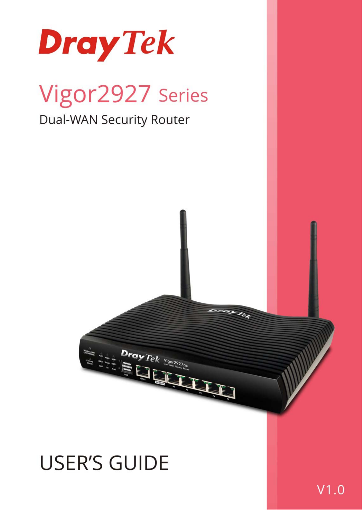
Vigor2927 Series
Dual-WAN Security Router
User’s Guide
Version: 1.0
Firmware Version: V4.2.0.1
(For future update, please visit DrayTek web site)
Date: August 5, 2020
ii
Vigor2927 Series User’s Guide
Page 3

Copyrights
© All rights reserved. This publication contains information that is protected by copyright. No part may be
reproduced, transmitted, transcribed, stored in a retrieval system, or translated into any language without
written permission from the copyright holders.
Trademarks
The following trademarks are used in this document:
Microsoft is a registered trademark of Microsoft Corp.
Windows, Windows 7, 8, 10 and Explorer are trademarks of Microsoft Corp.
Apple and Mac OS are registered trademarks of Apple Inc.
Other products may be trademarks or registered trademarks of their respective manufacturers.
Safety Instructions
Read the installation guide thoroughly before you set up the router.
The router is a complicated electronic unit that may be repaired only be authorized and qualified personnel.
Do not try to open or repair the router yourself.
Do not place the router in a damp or humid place, e.g. a bathroom.
The router should be used in a sheltered area, within a temperature range of +5 to +40 Celsius.
Do not expose the router to direct sunlight or other heat sources. The housing and electronic components
may be damaged by direct sunlight or heat sources.
Do not deploy the cable for LAN connection outdoor to prevent electronic shock hazards.
Keep the package out of reach of children.
When you want to dispose of the router, please follow local regulations on conservation of the environment.
Warranty
We warrant to the original end user (purchaser) that the router will be free from any defects in workmanship
or materials for a period of two (2) years from the date of purchase from the dealer. Please keep your
purchase receipt in a safe place as it serves as proof of date of purchase. During the warranty period, and upon
proof of purchase, should the product have indications of failure due to faulty workmanship and/or materials,
we will, at our discretion, repair or replace the defective products or components, without charge for either
parts or labor, to whatever extent we deem necessary tore-store the product to proper operating condition.
Any replacement will consist of a new or re-manufactured functionally equivalent product of equal value, and
will be offered solely at our discretion. This warranty will not apply if the product is modified, misused,
tampered with, damaged by an act of God, or subjected to abnormal working conditions. The warranty does
not cover the bundled or licensed software of other vendors. Defects which do not significantly affect the
usability of the product will not be covered by the warranty. We reserve the right to revise the manual and
online documentation and to make changes from time to time in the contents hereof without obligation to
notify any person of such revision or changes.
Be a Registered Owner
Web registration is preferred. You can register your Vigor router via http://www.DrayTek.com.
Firmware & Tools Updates
Due to the continuous evolution of DrayTek technology, all routers will be regularly upgraded. Please consult
the DrayTek web site for more information on newest firmware, tools and documents.
http://www.DrayTek.com
Vigor2927 Series User’s Guide
iii
Page 4

v
TTaabbllee ooff CCoonntteennttss
Part I Installation.................................................................................................................i
I-1 Introduction ................................................................................................................................... 1
I-1-1 Indicators and Connectors .................................................................................................. 2
I-1-1-1 Vigor2927 ................................................................................... 2
I-1-1-2 Vigor2927L.................................................................................. 4
I-1-1-3 Vigor2927ac / Vigor2927ax / Vigor2927Lac ........................................... 6
I-1-1-4 Vigor2927Vac ..............................................................................10
I-1-2 Notes for Antenna Installation (for “L” model)................................................................... 12
I-2 Hardware Installation .................................................................................................................. 14
I-2-1 Installing Vigor Router....................................................................................................... 14
I-2-2 Wall-Mounted Installation.................................................................................................. 15
I-2-3 Installing USB Printer to Vigor Router............................................................................... 16
I-3 Accessing Web Page.................................................................................................................. 23
I-4 Changing Password.................................................................................................................... 25
I-5 Dashboard................................................................................................................................... 27
I-5-1 Virtual Panel...................................................................................................................... 28
I-5-2 Name with a Link............................................................................................................... 29
I-5-3 Quick Access for Common Used Menu ............................................................................ 30
I-5-4 GUI Map ............................................................................................................................ 31
I-5-5 Web Console..................................................................................................................... 32
I-5-6 Config Backup................................................................................................................... 33
I-5-7 Logout................................................................................................................................ 33
I-5-8 Online Status..................................................................................................................... 34
I-5-8-1 Physical Connection......................................................................34
I-5-8-2 Virtual WAN ...............................................................................37
I-6 Quick Start Wizard...................................................................................................................... 38
I-6-1 For WAN1/WAN2 (Ethernet)............................................................................................. 39
I-6-2 For WAN3/WAN4 (Wireless 2.4G/Wireless 5G) ............................................................... 48
I-6-3 For WAN5/WAN6 (USB).................................................................................................... 54
I-7 Service Activation Wizard........................................................................................................... 56
I-8 Registering Vigor Router............................................................................................................. 58
Part II Connectivity ..........................................................................................................61
II-1 WAN........................................................................................................................................... 62
Web User Interface.................................................................................................................... 64
II-1-1 General Setup .................................................................................................................. 64
II-1-1-1 WAN1/WAN2 (Ethernet) ................................................................67
II-1-1-2 WAN3/WAN4 (Wireless 2.4G or 5G)...................................................69
II-1-1-3 WAN5 / WAN6 (USB) or WAN5 (LTE) ..................................................70
II-1-2 Internet Access................................................................................................................. 72
II-1-2-1 Details Page for PPPoE in WAN1/WAN2 (Physical Mode: Ethernet) .............75
i
Vigor2927 Series User’s Guide
Page 5

II-1-2-2 Details Page for Static or Dynamic IP in WA N1/WA N2 (Ph ysical M ode: E thernet)
.......................................................................................................78
II-1-2-3 Details Page for PPTP/L2TP in WAN1/WAN2 (Physical Mode: Ethernet) .......82
II-1-2-4 Details Page for Static or Dynamic IP in WAN3/WAN4 (Physical Mode: Wirele ss
2.4G/ Wireless 5G)................................................................................84
II-1-2-5 Details Page for 3G/4G USB Modem (PPP mode) in WAN5 / WAN6..............86
II-1-2-6 Details Page for 3G/4G USB Modem (DHCP mode) in WAN5 / WAN6............88
II-1-2-7 Details Page for IPv6 – Offline in WAN1~WAN6 .....................................90
II-1-2-8 Details Page for IPv6 – PPP in WAN1/WAN2 .........................................91
II-1-2-9 Details Page for IPv6 – TSPC in WAN1~WAN6........................................92
II-1-2-10 Details Page for IPv6 – AICCU in WAN1~WAN6.....................................94
II-1-2-11 Details Page for IPv6 – DHCPv6 Client in WAN1/WAN2...........................95
II-1-2-12 Details Page for IPv6 – Static IPv6 in WAN1/WAN2 ...............................97
II-1-2-13 Details Page for IPv6 – 6in4 Static Tunnel in WAN1/WAN2......................98
II-1-2-14 Details Page for IPv6 – 6rd in WAN1/WAN2 ...................................... 100
II-1-3 Multi-VLAN ..................................................................................................................... 102
II-1-4 WAN Budget................................................................................................................... 108
II-1-4-1 General Setup .......................................................................... 108
II-1-4-2 Status .................................................................................... 112
Application Notes.....................................................................................................................113
A-1 How to set up Multi-PVC for triple play deployment?................................ 113
II-2 LAN...........................................................................................................................................118
Web User Interface.................................................................................................................. 120
II-2-1 General Setup ................................................................................................................ 120
II-2-1-1 Details Page for LAN1 – Ethernet TCP/IP and DHCP Setup...................... 122
II-2-1-2 Details Page for LAN2 ~ LAN8 and DMZ ............................................ 126
II-2-1-3 Details Page for IP Routed Subnet .................................................. 128
II-2-1-4 Details Page for LAN IPv6 Setup..................................................... 130
II-2-1-5 DHCP Server Options .................................................................. 133
II-2-2 VLAN.............................................................................................................................. 135
II-2-3 Bind IP to MAC............................................................................................................... 139
II-2-4 LAN Port Mirror............................................................................................................... 142
II-2-5 Wired 802.1x .................................................................................................................. 143
II-3 Hardware Acceleration............................................................................................................. 144
II-3-1 Setup .............................................................................................................................. 144
II-4 NAT .......................................................................................................................................... 146
Web User Interface.................................................................................................................. 147
II-4-1 Port Redirection.............................................................................................................. 147
II-4-2 DMZ Host ....................................................................................................................... 151
II-4-3 Open Ports ..................................................................................................................... 154
II-4-4 Port Triggering................................................................................................................ 156
II-4-5 ALG................................................................................................................................. 158
II-5 Applications.............................................................................................................................. 158
Web User Interface.................................................................................................................. 161
II-5-1 Dynamic DNS................................................................................................................. 161
II-5-2 LAN DNS / DNS Forwarding.......................................................................................... 167
II-5-3 DNS Security..................................................................................................................171
II-5-3-1 General Setup .......................................................................... 171
Vigor2927 Series User’s Guide
v
Page 6

II-5-3-2 Domain Diagnose....................................................................... 172
II-5-4 Schedule......................................................................................................................... 173
II-5-5 RADIUS/TACACS+........................................................................................................ 176
II-5-5-1 External RADIUS........................................................................ 176
II-5-5-2 Internal RADIUS ........................................................................ 177
II-5-5-3 External TACACS+...................................................................... 180
II-5-6 Active Directory/LDAP.................................................................................................... 181
II-5-6-1 General Setup .......................................................................... 181
II-5-6-2 Active Directory / LDAP Profiles .................................................... 182
II-5-7 UPnP.............................................................................................................................. 183
II-5-8 IGMP............................................................................................................................... 185
II-5-8-1 General Setting ........................................................................ 185
II-5-8-2 Working Status ......................................................................... 186
II-5-9 Wake on LAN ................................................................................................................. 187
II-5-10 SMS / Mail Alert Service............................................................................................... 188
II-5-10-1 SMS Alert............................................................................... 188
II-5-10-2 Mail Alert.............................................................................. 189
II-5-11 Bonjour......................................................................................................................... 190
II-5-12 High Availability............................................................................................................ 193
II-5-12-1 General Setup......................................................................... 194
II-5-12-2 Config Sync ............................................................................ 196
II-5-13 Local 802.1X General Setup........................................................................................ 198
Application Notes.....................................................................................................................200
A-1 How to use High Availability?............................................................. 200
A-2 How to use DrayDDNS?..................................................................... 208
A-3 How to Implement the LDAP/AD Authentication for User Management? ......... 213
A-4 How to Configure Customized DDNS?.................................................... 216
II-6 Routing..................................................................................................................................... 220
Web User Interface.................................................................................................................. 221
II-5-1 Static Route.................................................................................................................... 221
II-6-2 Load-Balance /Route Policy........................................................................................... 226
Diagnose for Route Policy...................................................................... 231
II-6-3 BGP................................................................................................................................ 234
II-6-3-1 Basic Settings........................................................................... 234
II-6-3-2 Static Network ......................................................................... 235
Application Notes.....................................................................................................................236
A-1 How to set up Address Mapping with Route Policy? .................................. 236
A-2 How to use destination domain name in a route policy?............................. 238
A-3 Introduction to Load Balance/Route Policy ............................................ 240
II-7 L TE........................................................................................................................................... 242
Web User Interface.................................................................................................................. 243
II-7-1 General Settings............................................................................................................. 243
II-7-1-1 SMS Quota............................................................................... 243
II-7-1-2 SMS Inbox/Outbox ..................................................................... 244
II-7-2 SMS Inbox......................................................................................................................245
II-7-3 Send SMS ...................................................................................................................... 248
II-7-4 Router Commands ......................................................................................................... 249
vi
Vigor2927 Series User’s Guide
Page 7

II-7-5 Status ............................................................................................................................. 251
Part III Wireless LAN......................................................................................................253
III-1 Wireless LAN (2.4GHz/5GHz) ................................................................................................ 254
Web User Interface.................................................................................................................. 257
III-1-1 Wireless Wizard............................................................................................................. 257
III-1-2 General Setup ............................................................................................................... 261
III-1-3 Security.......................................................................................................................... 263
III-1-4 Access Control .............................................................................................................. 265
III-1-5 WPS............................................................................................................................... 267
III-1-6 WDS (for 5GHz) ............................................................................................................ 270
III-1-7 Advanced Setting .......................................................................................................... 272
III-1-8 Station Control............................................................................................................... 276
III-1-9 Bandwidth Management................................................................................................ 277
III-1-10 AP Discovery............................................................................................................... 278
III-1-11 Airtime Fairness........................................................................................................... 279
III-1-12 Band Steering (2.4 GHz).............................................................................................281
III-1-13 Roaming...................................................................................................................... 285
III-1-14 Station List................................................................................................................... 286
Part IV VPN.....................................................................................................................289
IV-1 VPN and Remote Access....................................................................................................... 290
Web User Interface.................................................................................................................. 291
IV-1-1 VPN Client Wizard ........................................................................................................ 291
IV-1-2 VPN Server Wizard....................................................................................................... 297
IV-1-3 Remote Access Control ................................................................................................ 305
IV-1-4 PPP General Setup....................................................................................................... 306
IV-1-5 SSL General Setup....................................................................................................... 308
IV-1-6 IPsec General Setup..................................................................................................... 309
IV-1-7 IPsec Peer Identity........................................................................................................ 312
IV-1-8 VPN Matcher Setup ...................................................................................................... 314
IV-1-9 OpenVPN......................................................................................................................316
IV-1-9-1 OpenVPN Server Setup ............................................................... 316
IV-1-9-2 Client Config........................................................................... 318
IV-1-10 Remote Dial-in User.................................................................................................... 320
IV-1-11 LAN to LAN................................................................................................................. 324
IV-1-12 VPN Trunk Management ............................................................................................ 333
IV-1-13 Connection Management............................................................................................ 340
Application Notes.....................................................................................................................342
A-1 How to Build a LAN-to-LAN VPN Between Vigor Routers via IPsec Main Mode ... 342
A-2 How to Build a LAN-to-LAN VPN Between Vigor Routers via IKEv2................. 347
IV-2 Certificate Management..........................................................................................................350
Web User Interface.................................................................................................................. 351
Vigor2927 Series User’s Guide
vii
Page 8

IV-2-1 Local Certificate ............................................................................................................ 351
IV-2-2 Trusted CA Certificate................................................................................................... 356
IV-2-3 Certificate Backup......................................................................................................... 359
IV-2-4 Self-Signed Certificate .................................................................................................. 360
Part V Security...............................................................................................................361
V-1 Firewall.....................................................................................................................................362
Web User Interface.................................................................................................................. 364
V-1-1 General Setup................................................................................................................ 364
V-1-2 Filter Setup..................................................................................................................... 369
V-1-3 Defense Setup ............................................................................................................... 379
V-1-3-1 DoS Defense............................................................................. 379
V-1-3-2 Spoofing Defense....................................................................... 382
V-1-4 Diagnose........................................................................................................................ 383
V-2 Central Security Management (CS M)...................................................................................... 386
Web User Interface.................................................................................................................. 387
V-2-1 APP Enforcement Profile............................................................................................... 387
V-2-2 APPE Signature Upgrade.............................................................................................. 389
V-2-3 URL Content Filter Profile.............................................................................................. 391
V-2-4 Web Content Filter Profile.............................................................................................. 395
V-2-5 DNS Filter Profile ........................................................................................................... 398
Application Notes.....................................................................................................................400
A-1 How to Create an Account for MyVigor ................................................. 400
A-2 How to Block Facebook Service Accessed by the Use rs via W e b Cont ent Fil ter / UR L
Content Filter.................................................................................... 405
Part VI Management
VI-1 System Maintenance.............................................................................................................. 412
Web User Interface.................................................................................................................. 413
VI-1-1 System Status...............................................................................................................413
VI-1-2 TR-069 .......................................................................................................................... 415
VI-1-3 Administrator Password................................................................................................ 418
VI-1-4 User Password.............................................................................................................. 421
VI-1-5 Login Page Greeting..................................................................................................... 424
......................................................................................................411
VI-1-6 Configuration Backup.................................................................................................... 426
VI-1-7 Syslog/Mail Alert ........................................................................................................... 429
VI-1-8 Time and Date............................................................................................................... 432
VI-1-9 SNMP............................................................................................................................ 433
VI-1-10 Management............................................................................................................... 435
VI-1-11 Panel Control .............................................................................................................. 439
VI-1-12 Self-Signed Certificate ................................................................................................ 444
VI-1-13 Reboot System............................................................................................................ 446
VI-1-14 Firmware Upgrade ...................................................................................................... 447
viii
Vigor2927 Series User’s Guide
Page 9

VI-1-15 Firmware Backup........................................................................................................ 448
VI-1-16 Internal Service User List............................................................................................ 449
VI-1-17 Dashboard Control...................................................................................................... 450
VI-2 Bandwidth Management......................................................................................................... 451
Web User Interface.................................................................................................................. 452
VI-2-1 Sessions Limit...............................................................................................................452
VI-2-2 Bandwidth Limit............................................................................................................. 454
VI-2-3 Quality of Service.......................................................................................................... 456
VI-2-4 APP QoS....................................................................................................................... 462
VI-3 User Management.................................................................................................................. 463
Web User Interface.................................................................................................................. 464
VI-3-1 General Setup............................................................................................................... 464
VI-3-2 User Profile ................................................................................................................... 466
VI-3-3 User Group.................................................................................................................... 470
VI-3-4 User Online Status........................................................................................................ 471
Application Notes.....................................................................................................................473
A-1 How to authenticate clients via User Management................................... 473
A-2 How to use Landing Page Feature ....................................................... 482
VI-4 Hotspot Web Portal................................................................................................................. 486
Web User Interface.................................................................................................................. 486
VI-4-1 Profile Setup.................................................................................................................. 486
VI-4-1-1 Login Method .......................................................................... 487
VI-4-1-2 Steps for Configuring a Web Portal Profile....................................... 487
VI-4-2 User Information............................................................................................................ 503
VI-4-2-1 User Info................................................................................ 503
VI-4-2-2 Database Setup........................................................................ 504
VI-4-3 Quota Management ...................................................................................................... 506
VI-4-4 PIN Generator............................................................................................................... 509
VI-4-4-1 PIN Status .............................................................................. 509
VI-4-4-2 PIN Generator.......................................................................... 510
VI-4-4-3 PIN Voucher ............................................................................ 511
Application Notes.....................................................................................................................513
A-1 How to create Facebook APP for Web Portal Authentication?...................... 513
A-2 How to create Google APP for Web Portal Authentication?......................... 519
VI-5 Central Management (VPN)................................................................................................... 521
Web User Interface.................................................................................................................. 522
VI-5-1 General Setup............................................................................................................... 522
VI-5-1-1 General Settings....................................................................... 522
VI-5-1-2 IPsec VPN Settings .................................................................... 523
VI-5-2 CPE Management......................................................................................................... 524
VI-5-2-1 Managed Device List.................................................................. 524
VI-5-2-2 CPE Maintenance...................................................................... 527
VI-5-2-3 Google Map............................................................................. 529
VI-5-3 VPN Management......................................................................................................... 531
VI-5-4 Log & Alert .................................................................................................................... 532
Vigor2927 Series User’s Guide
ix
Page 10

x
Application Notes.....................................................................................................................533
A-1 CVM Application - How to manage the CPE (router) through Vigor2927 series? . 533
A-2 CVM Application - How to build the VPN between remote devices and Vigor 2927
series? ............................................................................................. 537
A-3 CVM Application - How to upgrade CPE firmware through Vigor2927 series?.... 539
VI-6 Central Management (AP)...................................................................................................... 542
Web User Interface.................................................................................................................. 543
VI-6-1 Dashboard..................................................................................................................... 543
VI-6-2 Status............................................................................................................................ 544
VI-6-3 WLAN Profile................................................................................................................. 545
VI-6-4 AP Maintenance............................................................................................................ 550
VI-6-5 AP Map ......................................................................................................................... 551
VI-6-6 Traffic Graph................................................................................................................. 556
VI-6-7 Event Log......................................................................................................................557
VI-6-8 Total Traffic................................................................................................................... 558
VI-6-9 Station Number............................................................................................................. 558
VI-6-10 Load Balance.............................................................................................................. 559
VI-7 Central Management (Switch)................................................................................................ 561
Web User Interface.................................................................................................................. 562
VI-7-1 Status............................................................................................................................ 562
VI-7-1-1 Switch Status .......................................................................... 562
VI-7-1-2 Switch Hierarchy...................................................................... 564
VI-7-2 Profile............................................................................................................................ 565
VI-7-3 Group ............................................................................................................................ 568
VI-7-4 Maintenance.................................................................................................................. 570
VI-7-5 Alert and Log................................................................................................................. 571
VI-7-5-1 Alert Setup............................................................................. 571
VI-7-5-2 Switch and Port Setup................................................................ 571
VI-7-5-3 Alert Logs .............................................................................. 573
VI-7-6 Database Setup ............................................................................................................ 574
VI-7-7 Support List................................................................................................................... 575
VI-8 Central Management (External Devices) ............................................................................... 576
Part VII Others................................................................................................................579
VII-1 Objects Settings..................................................................................................................... 580
Web User Interface.................................................................................................................. 581
VII-1-1 IP Object ...................................................................................................................... 581
VII-1-2 IP Group....................................................................................................................... 584
VII-1-3 IPv6 Object................................................................................................................... 586
VII-1-4 IPv6 Group...................................................................................................................588
VII-1-5 Service Type Object..................................................................................................... 590
VII-1-6 Service Type Group..................................................................................................... 592
VII-1-7 Keyword Object............................................................................................................ 594
VII-1-8 Keyword Group............................................................................................................ 596
Vigor2927 Series User’s Guide
Page 11

xi
VII-1-9 File Extension Object................................................................................................... 597
VII-1-10 SMS/Mail Service Object........................................................................................... 599
VII-1-11 Notification Object...................................................................................................... 604
VII-1-12 String Object .............................................................................................................. 607
VII-1-13 Country Object........................................................................................................... 608
VII-1-14 Objects Backup/Restore ............................................................................................ 611
Application Notes.....................................................................................................................612
A-1 How to Send a Notification to Specified Phone Number via SMS Service in WAN
Disconnection .................................................................................... 612
VII-2 USB Application..................................................................................................................... 616
Web User Interface.................................................................................................................. 617
VII-2-1 USB General Settings.................................................................................................. 617
VII-2-2 USB User Management............................................................................................... 618
VII-2-3 File Explorer................................................................................................................. 620
VII-2-4 USB Device Status....................................................................................................... 621
VII-2-5 Temperature Sensor.................................................................................................... 622
VII-2-6 Modem Support List..................................................................................................... 625
VII-2-7 SMB Client Support List............................................................................................... 626
Application Notes.....................................................................................................................627
A-1 How can I get the files from USB storage device connecting to Vigor router? ... 627
Part VIII Troubleshooting ..............................................................................................631
VIII-1 Diagnostics........................................................................................................................... 632
Web User Interface.................................................................................................................. 633
VIII-1-1 Dial-out Triggering....................................................................................................... 633
VIII-1-2 Routing Table.............................................................................................................. 634
VIII-1-3 ARP Cache Table ....................................................................................................... 635
VIII-1-4 IPv6 Neighbour Table ................................................................................................. 636
VIII-1-5 DHCP Table................................................................................................................ 637
VIII-1-6 NAT Sessions Table ................................................................................................... 638
VIII-1-7 DNS Cache Table....................................................................................................... 639
VIII-1-8 Ping Diagnosis............................................................................................................ 640
VIII-1-9 Data Flow Monitor....................................................................................................... 641
VIII-1-10 Traffic Graph............................................................................................................. 644
VIII-1-11 VPN Graph................................................................................................................ 645
VIII-1-12 Trace Route .............................................................................................................. 646
VIII-1-13 Syslog Explorer......................................................................................................... 647
VIII-1-14 IPv6 TSPC Status..................................................................................................... 648
VIII-1-15 High Availability Status ............................................................................................. 648
VIII-1-16 Authentication Information........................................................................................ 650
VIII-1-17 DoS Flood Table....................................................................................................... 652
VIII-1-18 Route Policy Diagnosis............................................................................................. 653
Vigor2927 Series User’s Guide
Page 12

xii
VIII-2 Checking If the Hardware Status Is OK or Not..................................................................... 655
VIII-3 Checking If the Network Connection Settings on Your Computer Is OK or Not................... 656
VIII-4 Pinging the Router from Your Computer .............................................................................. 659
VIII-5 Checking If the ISP Settings are OK or Not ......................................................................... 661
VIII-6 Problems for 3G/4G Network Connection............................................................................ 662
VIII-7 Backing to Factory Default Setting If Necessary.................................................................. 663
VIII-8 Contacting DrayTek.............................................................................................................. 664
Appendix I: VLAN Applications on Vigor Router ............................................................................ 665
Part IX Telnet Commands
Accessing Telnet of Vigor2927....................................................................................................... 674
..............................................................................................673
Index ...............................................................................................................................928
Vigor2927 Series User’s Guide
Page 13

P
arrtt II II
P
a
nsstt
n
allll
a
attii
a
o
o
n
n
This part will introduce Vigor router and guide to
install the device in hardware and software.
Page 14

Page 15

II--11 IInnttrroodduuccttiioonn
TThhiiss iiss aa ggeenneerriicc IInntteerrnnaattiioonnaall vveerrssiioonn ooff tthhee uusseerr gguuiiddee.. SSppeecciiffiiccaattiioonn,,
ccoommppaattiibbiilliittyy aanndd ffeeaattuurreess vvaarryy bbyy rreeggiioonn.. FFoorr ssppeecciiffiicc uusseerr gguuiiddeess
ssuuiittaabbllee ffoorr yyoouurr rreeggiioonn oorr pprroodduucctt,, pplleeaassee ccoonnttaacctt llooccaall ddiissttrriibbuuttoorr..
Vigor2927 series integrates IP layer QoS, NAT session/bandwidth management to help users
control works well with large bandwidth.
By adopting hardware-based VPN platform and hardware encryption of AES/DES/3DES, the
router increases the performance of VPN greatly, and offers several protocols (such as
IPsec/PPTP/L2TP) with VPN tunnels.
The object-based design used in SPI (Stateful Packet Inspection) firewall allows users to set
firewall policy with ease. CSM (Content Security Management) provides users control and
management in IM (Instant Messenger) and P2P (Peer to Peer) more efficiency than before. By
the way, DoS/DDoS prevention and URL/Web content filter strengthen the security outside
and control inside. Object-based firewall is flexible and allows your network be safe.
User Management implemented on your router firmware can allow you to prevent any
computer from accessing your Internet connection without a username or password. You can
also allocate time budgets to your employees within office network.
With the 4-port Gigabit switch on the LAN side provides extremely high speed connectivity for
the highest speed local data transfer of any server or local PCs. The tagged VLANs
(IEEE802.1Q) can mark data with a VLAN identifier. This identifier can be carried through an
onward Ethernet switch to specific ports. The specific VLAN clients can al so pick up this
identifier as it is just passed to the LAN. You can set the priorities for LAN-side QoS. You can
assign each of VLANs to each of the different IP subnets that the router may also be operating,
to provide even more isolation. The said functionality is tag-based Multi-subnet
(Multiple-Private LAN Subnets).
On the Wireless-equipped models (e.g., Vigor2927lac) each of the wireless SSIDs can also be
grouped within one of the VLANs.
In addition, Vigor2927 series supports USB interface for c onnecting USB printer to share
printing function or 3G USB modem for network connection.
Vigor2927 series provides two-level management to simplify the configuration of network
connection. The user mode allows user accessing into WEB interfa ce via simple configuration .
However, if users want to have advanced configurations, they can access into WEB interface
through admin mode.
Vigor2927 Series User’s Guide
1
Page 16
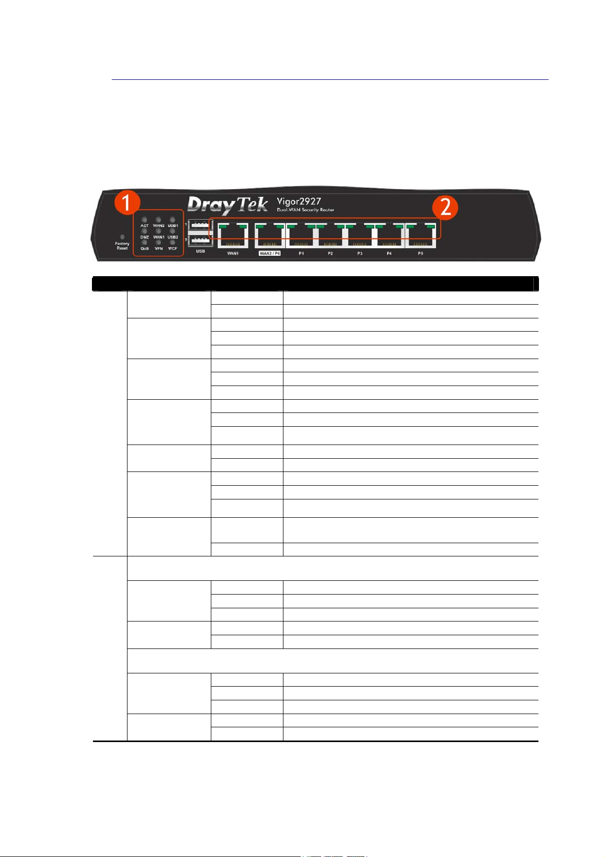
II--11--11 IInnddiiccaattoorrss aanndd CCoonnnneeccttoorrss
Before you use the Vigor router, please get acquainted with the LED indicators and
connectors first.
II--11--11--11 VViiggoorr22992277
No. LED Status Explanation
ACT
WAN2/WAN1
USB1/USB2
(1)
DMZ
Off The router is powered off.
Blinking The router is powered on and running normally.
On Internet connection is ready.
Off Internet connection is not ready.
Blinking The data is transmitting.
On USB device is connected and ready for use.
Off No USB device is connected.
Blinking The data is transmitting.
On The DMZ function is enabled.
Off The DMZ function is disabled.
Blinking The data is transmitting.
(2)
QoS
VPN
WCF
WAN1,WAN2 / P6
Left LED
Right LED
LAN P1-P5
Left LED
Right LED
On The QoS function is active.
Off The QoS function is inactive.
On The VPN tunnel is active.
Off VPN services are disabled
Blinking
On
Off WCF is disabled.
On The port is connected.
Off The port is disconnected.
Blinking The data is transmitting.
On The port is connected with 1000Mbps.
Off The port is connected with 10/100Mbps.
On The port is connected.
Off The port is disconnected.
Blinking The data is transmitting.
On The port is connected with 1000Mbps.
Off The port is connected with 10/100Mbps
Traffic is passing through VPN tunnel.
The Web Content Filter is active. (It is enabled from
Firewall >> General Setup).
2
Vigor2927 Series User’s Guide
Page 17
No.
(3)
(4)
(5)
(6)
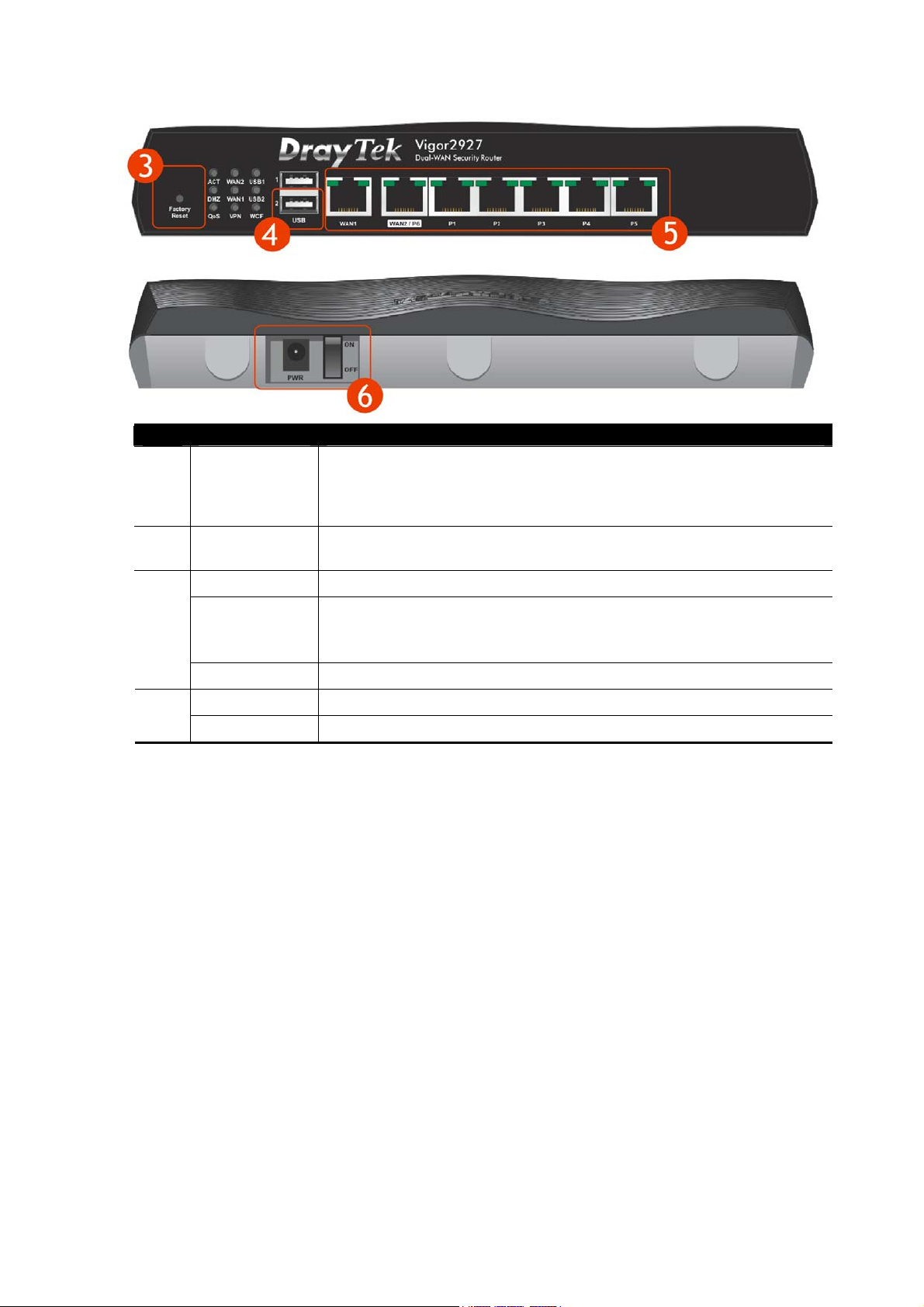
Interface Description
Restore the default settings. Usage: Turn on the router (ACT LED is
Factory Reset
blinking). Press the hole and keep for more than 5 seconds. When you
see the ACT LED begins to blink rapidly than usual, release the button.
Then the router will restart with the factory default configuration.
USB
Connecter for a USB device (for 3G/4G USB Modem or printer or
thermometer).
WAN1 Connecter for local network devices or modem for accessing Internet.
Connecter for local network devices or modem for accessing Internet.
WAN2 / P6
It is a switchable port. It can be used for LAN connection or WAN
connection according to the settings configured in WUI.
LAN P1-P5 Connecters for local network devices.
PWR Connecter for a power adapter.
ON/OFF Power Switch.
Vigor2927 Series User’s Guide
3
Page 18
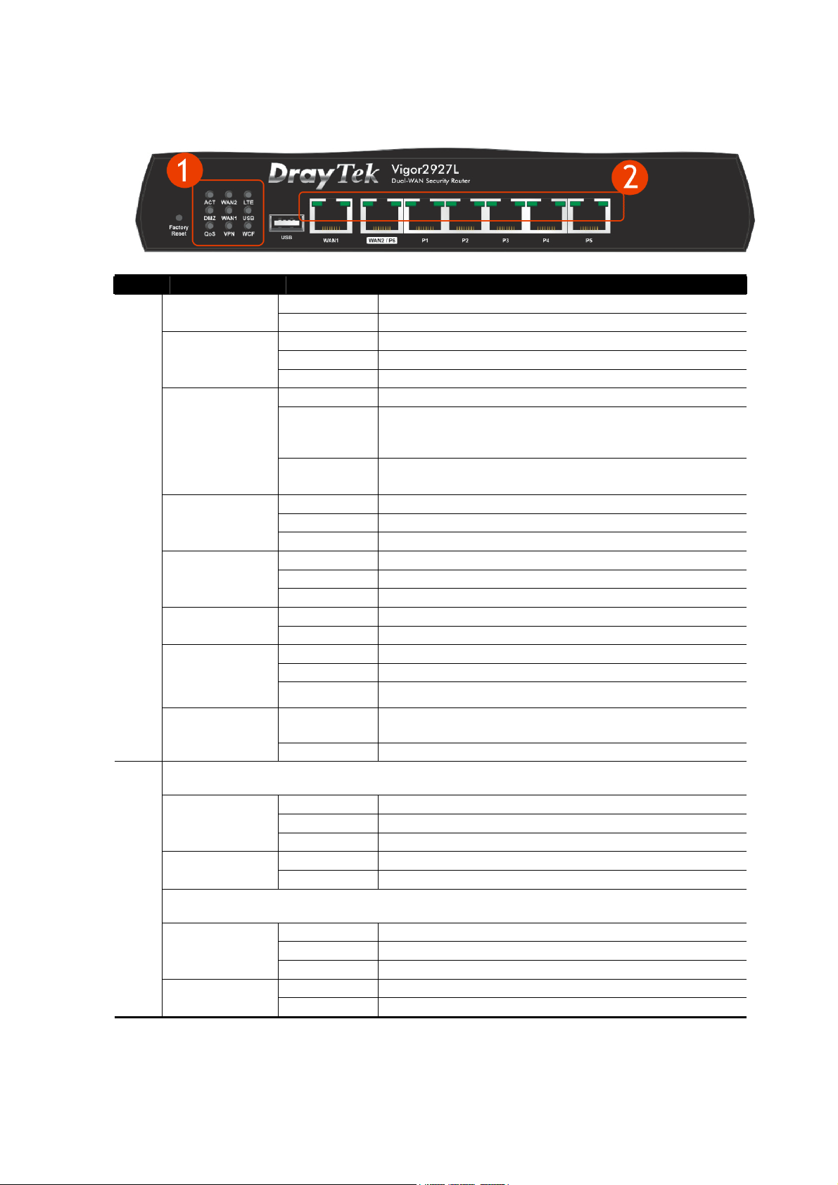
II--11--11--22 VViiggoorr22992277LL
No. LED Status Explanation
ACT
WAN2/WAN1
LTE
(1)
DMZ
USB
QoS
VPN
WCF
Off The router is powered off.
Blinking The router is powered on and running normally.
On Internet connection is ready.
Off Internet connection is not ready.
Blinking The data is transmitting.
On LTE device is connected and ready for use.
Off LTE device is not detected, or has serious problem
(e.g., no SIM card, SIM pin error, SIM deactivated, and
etc.).
Blinking Slowly: LTE device is in dialing up.
Quickly: The data is transmitting.
On The DMZ function is enabled.
Off The DMZ function is disabled.
Blinking The data is transmitting.
On USB device is connected and ready for use.
Off No USB device is connected.
Blinking The data is transmitting.
On The QoS function is active.
Off The QoS function is inactive.
On The VPN tunnel is active.
Off VPN services are disabled
Blinking
On The Web Content Filter is active. (It is enabled from
Off WCF is disabled.
Traffic is passing through VPN tunnel.
Firewall >> General Setup).
WAN1,WAN2 / P6
On The port is connected.
Left LED
Right LED
(2)
LAN P1-P5
Left LED
Right LED
4
Off The port is disconnected.
Blinking The data is transmitting.
On The port is connected with 1000Mbps.
Off The port is connected with 10/100Mbps.
On The port is connected.
Off The port is disconnected.
Blinking The data is transmitting.
On The port is connected with 1000Mbps.
Off The port is connected with 10/100Mbps
Vigor2927 Series User’s Guide
Page 19
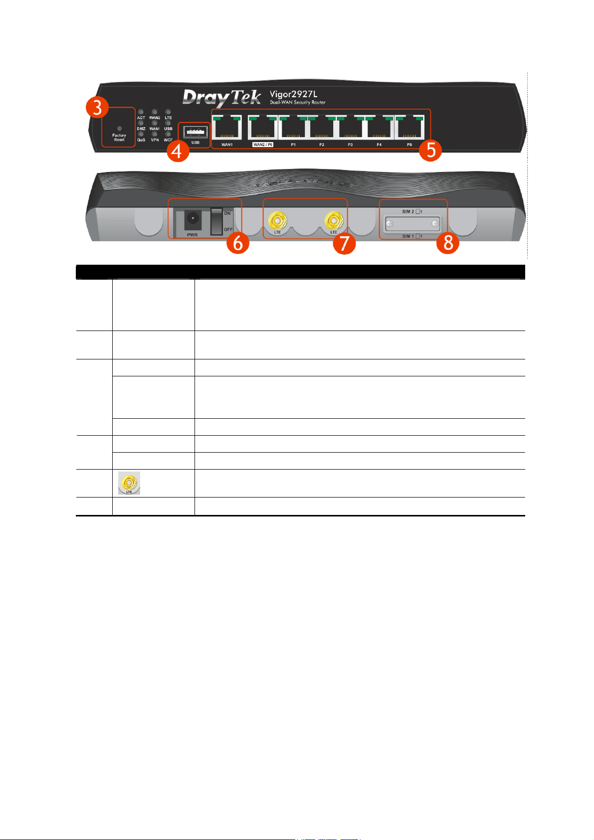
No.
(3)
(4)
(5)
(6)
(7)
(8)
Interface Description
Restore the default settings. Usage: Turn on the router (ACT LED is
Factory Reset
blinking). Press the hole and keep for more than 5 seconds. When you
see the ACT LED begins to blink rapidly than usual, release the button.
Then the router will restart with the factory default configuration.
USB
Connecter for a USB device (for 3G/4G USB Modem or printer or
thermometer).
WAN1 Connecter for local network devices or modem for accessing Internet.
Connecter for local network devices or modem for accessing Internet.
WAN2 / P6
It is a switchable port. It can be used for LAN connection or WAN
connection according to the settings configured in WUI.
LAN P1-P5 Connecters for local network devices.
PWR Connecter for a power adapter.
ON/OFF Power Switch.
Connecter for installing LTE antennas.
SIM 2/1
Slots for installing SIM card.
Vigor2927 Series User’s Guide
5
Page 20
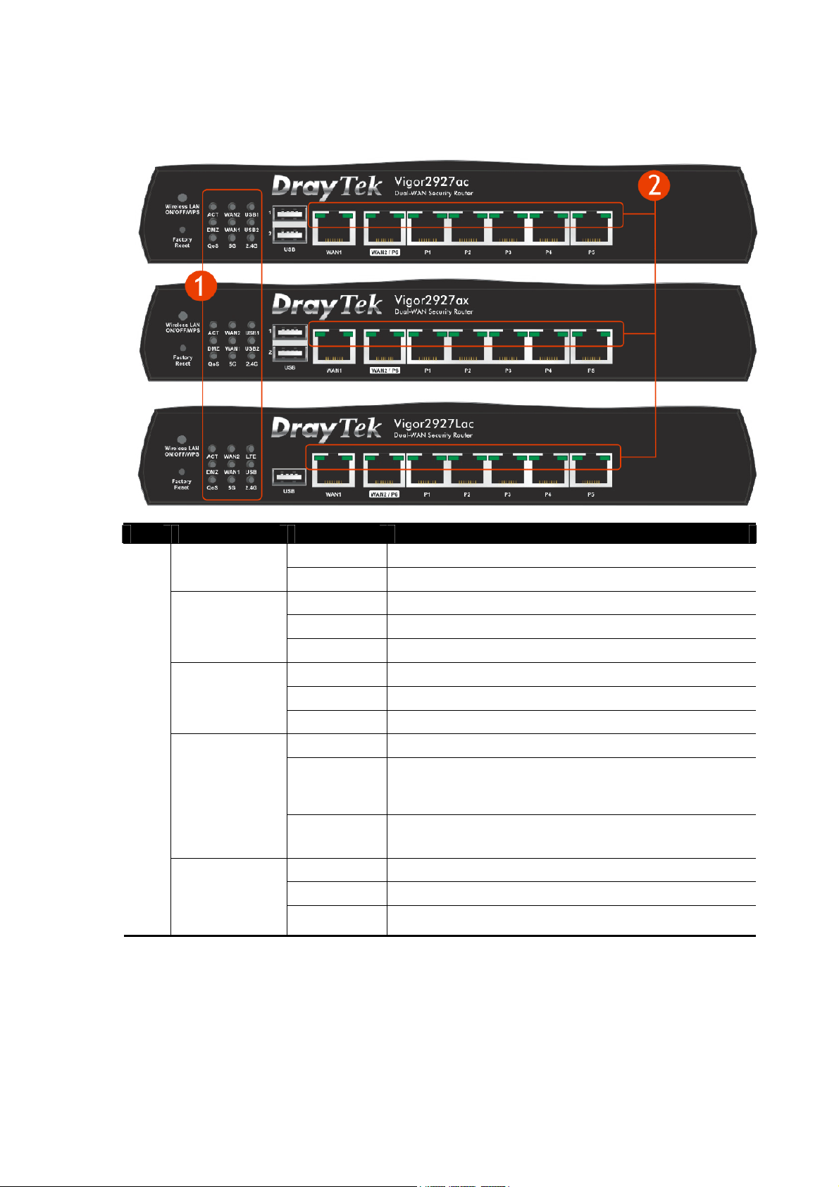
II--11--11--33 VViiggoorr22992277aacc // VViiggoorr22992277aaxx // VViiggoorr22992277LLaacc
No. LED Status Explanation
ACT
WAN2/WAN1
USB1/USB2
(1)
LTE
DMZ
Off The router is powered off.
Blinking The router is powered on and running normally.
On Internet connection is ready.
Off Internet connection is not ready.
Blinking The data is transmitting.
On USB device is connected and ready for use.
Off No USB device is connected.
Blinking The data is transmitting.
On LTE device is connected and ready for use.
Off LTE device is not detected, or has serious problem
(e.g., no SIM card, SIM pin error, SIM deactivated, and
etc.).
Blinking Slowly: LTE device is in dialing up.
Quickly: The data is transmitting.
On The DMZ function is enabled.
Off The DMZ function is disabled.
Blinking The data is transmitting.
6
Vigor2927 Series User’s Guide
Page 21

(1)
(2)
QoS
5G / 2.4G
WAN1,WAN2 / P6
Left LED
Right LED
LAN P1-P5
Left LED
Right LED
On The QoS function is active.
Off The QoS function is inactive.
5G / 2.4G: Wireless access point with bandwidth of
On
5GHz/2.4GHz is ready.
WLAN: Wireless access point is ready.
Off Wireless function is disabled.
It will blink slowly while wireless traffic goes through.
ACT and WLAN LEDs blink quickly and simultaneously
Blinking
when WPS is working, and will return to normal
condition after two minutes. (You need to setup WPS
within 2 minutes.)
On The port is connected.
Off The port is disconnected.
Blinking The data is transmitting.
On The port is connected with 1000Mbps.
Off The port is connected with 10/100Mbps.
On The port is connected.
Off The port is disconnected.
Blinking The data is transmitting.
On The port is connected with 1000Mbps.
Off The port is connected with 10/100Mbps
Vigor2927 Series User’s Guide
7
Page 22
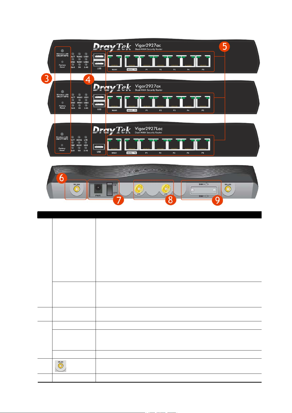
(7)
No.
Interface Description
Wireless band will be switched /changed according to the button pressed
and released. For example,
2.4G (On) and 5G (On) – in default.
2.4G (Off) and 5G (On) – pressed and released the button once.
Wireless LAN
ON/OFF/WPS
(3)
Factory Reset
USB1~2 / USB
(4)
WAN1 Connecter for local network devices or modem for accessing Internet.
WAN2 / P6
(5)
LAN P1-P5 Connecters for local network devices.
(6)
PWR Connecter for a power adapter.
2.4G (On) and 5G (Off) – pressed and released the button twice.
2.4G (Off) and 5G (Off) – pressed and released the button three
times.
When WPS function is enabled by web user interface, press this button
for mor e t h a n 2 se conds to wait for clien t’s device maki ng
connection through WPS.
Restore the default settings. Usage: Turn on the router (ACT LED is
blinking). Press the hole and keep for more than 5 seconds. When you see
the ACT LED begins to blink rapidly than usual, release the button. Then
the router will restart with the factory default configuration.
Connecter for a USB device (for 3G/4G USB Modem or printer or
thermometer).
Connecter for local network devices or modem for accessing Internet.
It is a switchable port. It can be used for LAN connection or WAN
connection according to the settings configured in WUI.
Connecter for installing WLAN antennas.
(For ac model)
network
8
Vigor2927 Series User’s Guide
Page 23

ON/OFF Power Switch.
(8)
(9)
SIM 2/1
Connecter for installing LTE antennas.
(For L model).
Slots for installing SIM card.
(For L model).
Vigor2927 Series User’s Guide
9
Page 24
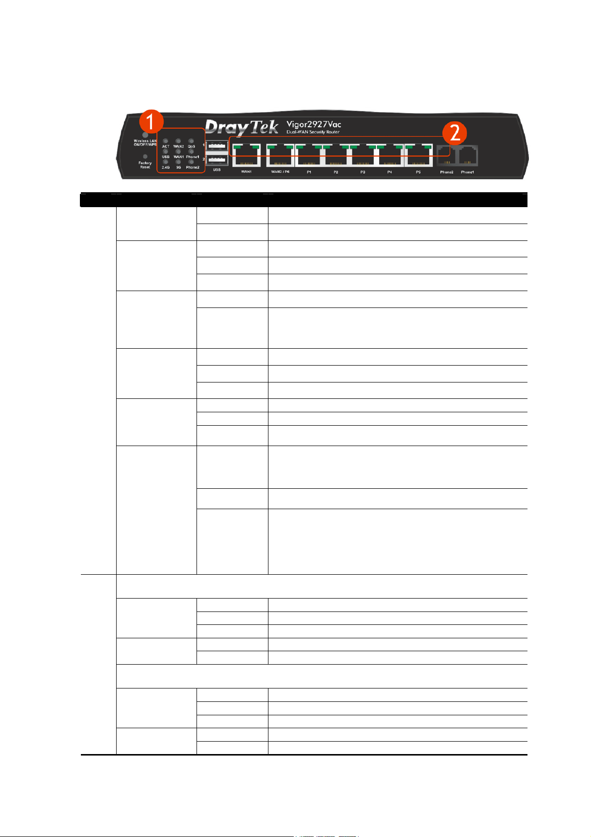
II--11--11--44 VViiggoorr22992277VVaacc
No. LED Status Explanation
ACT
WAN2/WAN1
QoS
USB
(1)
Phone1/Phone
2
Off The router is powered off.
Blinking The router is powered on and running normally.
On Internet connection is ready.
Off Internet connection is not ready.
Blinking The data is transmitting.
On The QoS function is active.
Off The QoS function is inactive.
On USB device is connected and ready for use.
Off No USB device is connected.
Blinking The data is transmitting.
On The phone connected to this port is off-hook.
Off The phone connected to this port is on-hook.
Blinking A phone call comes.
(2)
2.4G/5G
WAN1,WAN2 / P6
Left LED
Right LED
LAN P1-P5
Left LED
Right LED
5G / 2.4G: Wireless access point with bandwidth of
On
Off
Blinking
On The port is connected.
Off The port is disconnected.
Blinking The data is transmitting.
On The port is connected with 1000Mbps.
Off The port is connected with 10/100Mbps.
On The port is connected.
Off The port is disconnected.
Blinking The data is transmitting.
On The port is connected with 1000Mbps.
Off The port is connected with 10/100Mbps
5GHz/2.4GHz is ready.
WLAN: Wireless access point is ready.
Wireless function is disabled.
It will blink slowly while wireless traffic goes through.
ACT and WLAN LEDs blink quickly and simultaneously
when WPS is working, and will return to normal
condition after two minutes. (You need to setup WPS
within 2 minutes.)
10
Vigor2927 Series User’s Guide
Page 25
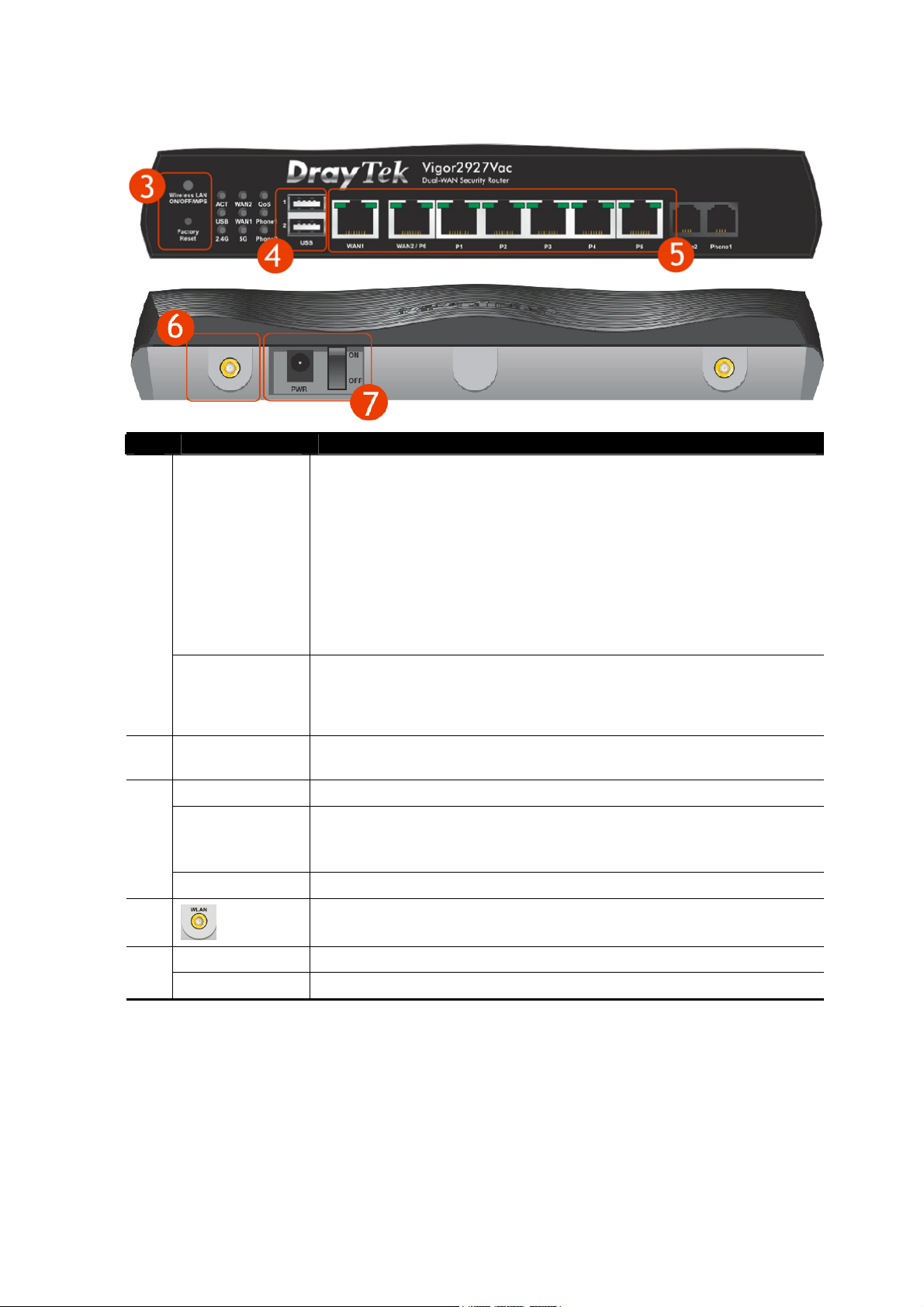
No.
(3)
(4)
(5)
(6)
(7)
Interface Description
Wireless band will be switched /changed according to the button
pressed and released. For example,
2.4G (On) and 5G (On) – in default.
2.4G (Off) and 5G (On) – pressed and released the button once.
Wireless LAN
ON/OFF/WPS
Factory Reset
USB1~2 / USB
WAN1 Connecter for local network devices or modem for accessing Internet.
WAN2 / P6
LAN P1-P5 Connecters for local network devices.
PWR Connecter for a power adapter.
ON/OFF Power Switch.
2.4G (On) and 5G (Off) – pressed and released the button twice.
2.4G (Off) and 5G (Off) – pressed and released the button three
times.
When WPS function is enabled by web user interface, press this button
for mor e t h a n 2 se conds to wait for clien t’s device maki ng
connection through WPS.
Restore the default settings. Usage: Turn on the router (ACT LED is
blinking). Press the hole and keep for more than 5 seconds. When you
see the ACT LED begins to blink rapidly than usual, release the button.
Then the router will restart with the factory default configuration.
Connecter for a USB device (for 3G/4G USB Modem or printer or
thermometer).
Connecter for local network devices or modem for accessing Internet.
It is a switchable port. It can be used for LAN connection or WAN
connection according to the settings configured in WUI.
Connecter for installing WLAN antennas.
(For ac model)
network
Vigor2927 Series User’s Guide
11
Page 26
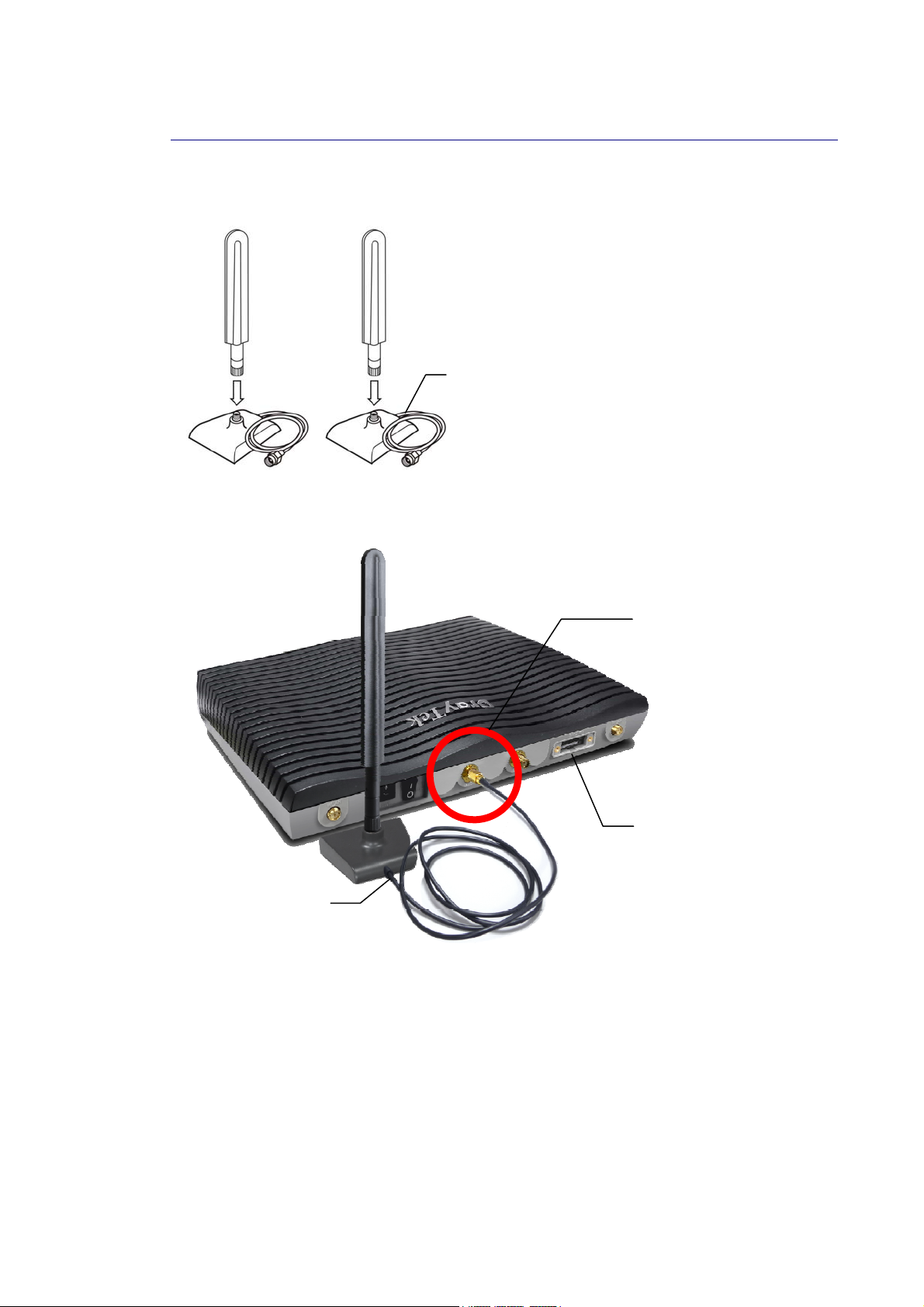
“
L
II--11--22 NNootteess ffoorr AAnntteennnnaa IInnssttaallllaattiioonn ((ffoorr
Magnetic antenna must be installed on the extension base before connecting to Vigor router.
Extension Base
There are two mounting holes for installing antennas with extension base on Vigor router.
Please install them as shown below.
”
“
L
”
mmooddeell))
Major Signal
Transmitted Hole
SIM Card
Slot
Extension Base
Note, if only one antenna shall be installed, please use the mounting hole (major signal
transmitted hole) near to the power switch.
12
Vigor2927 Series User’s Guide
Page 27
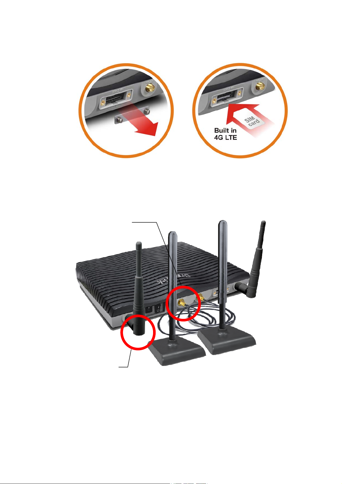
While installing the SIM card into the card slot, note that back plate of the SIM card slot must
be removed first and the direction of card notch must be on the left side.
There are two types of antennas provided for Vigor2927Lac, which must be installed in
different locations carefully and correctly. Wrong installation might cause bad signal of
wireless connection. Therefore, pay attention to the i n s t al l a t i o n o f an t e n n a s b y r ef e r r i n g t o t he
following illustration.
SMA jack for LTE Antenna (with
extension base)
SMA jack for WLAN
Antenna
Vigor2927 Series User’s Guide
13
Page 28
4
II--22 HHaarrddwwaarree IInnssttaallllaattiioonn
II--22--11 IInnssttaalllliinngg VViiggoorr RRoouutteerr
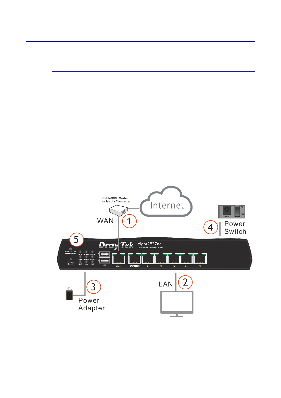
Before starting to configure the router, you have to connect your devices correctly. (For the
hardware connection, we take “ac” model as an example.)
1. Connect the DSL interface to the land line jack with a DSL line cable.
Connect the cable Modem/DSL Modem/Media Converter to the WAN port of router with
Ethernet cable (RJ-45).
2. Connect one end of an Ethernet cable (RJ-45) to one of the LAN ports of the router and
the other end of the cable (RJ-45) into the Ethernet port on your computer.
3. Connect one end of the power adapter to the router’s power port on the rear panel, and
the other side into a wall outlet.
4. Power on the device by pressing down the power switch on the rear panel.
5. The system starts to initiate. After completing the system test, the ACT LED will light up
and start blinking.
(For the hardware connection, we take “ac” model as an example.)
1
Vigor2927 Series User’s Guide
Page 29
II--22--22 WWaallll--MMoouunntteedd IInnssttaallllaattiioonn
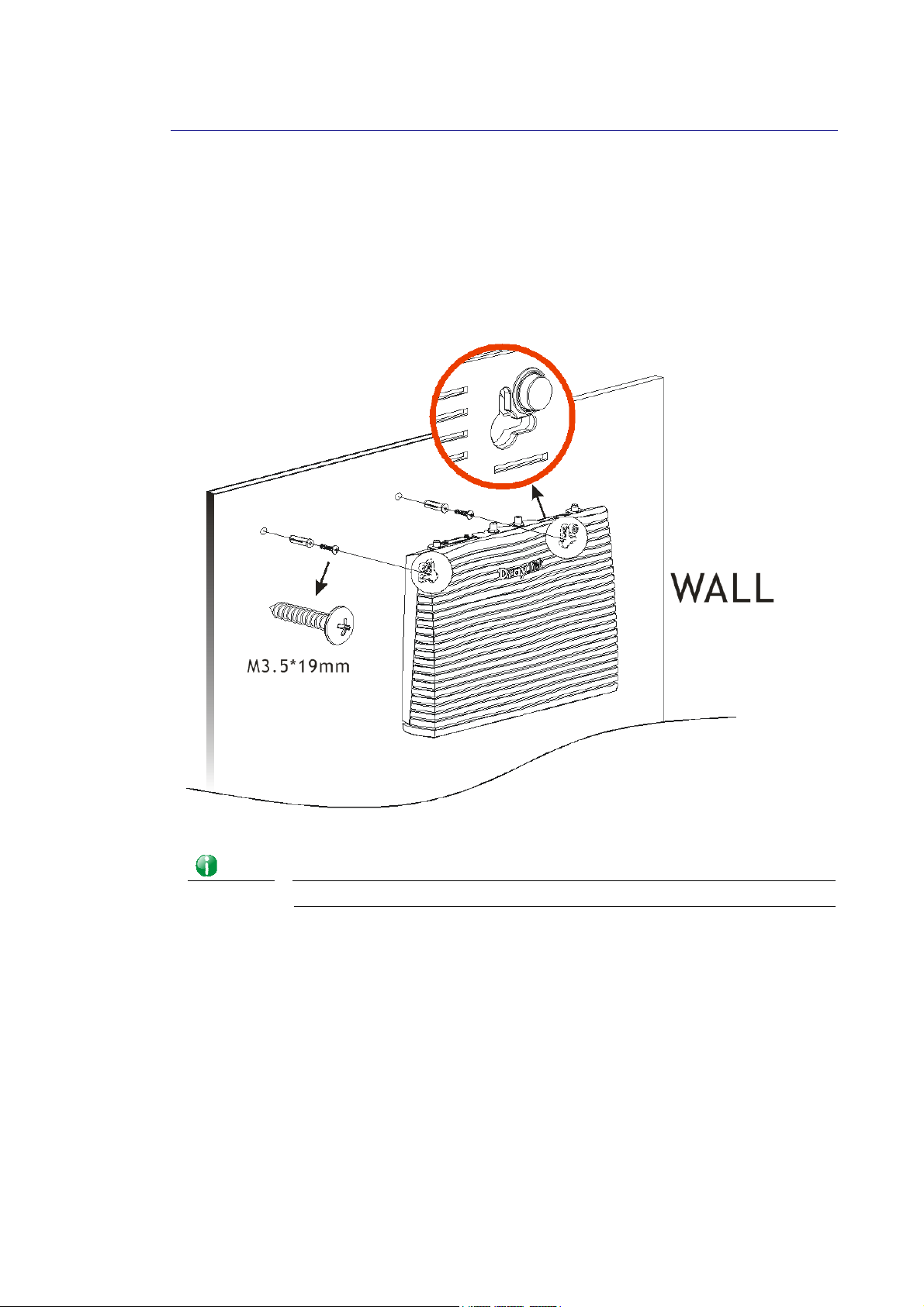
Vigor router has keyhole type mounting slots on the underside.
1. A template is provided on the Vigor router packaging box to enable you to space the
screws correctly on the wall.
2. Place the template on the wall and drill the holes according to the recommended
instruction.
3. Fit screws into the wall using the appropriate type of wall plug.
Info
4. When you finished about procedure, the router has been mounted on the wall firmly.
Vigor2927 Series User’s Guide
The recommended drill diameter shall be 6.5mm (1/4”).
15
Page 30
II--22--33 IInnssttaalllliinngg UUSSBB PPrriinntteerr ttoo VViiggoorr RRoouutteerr
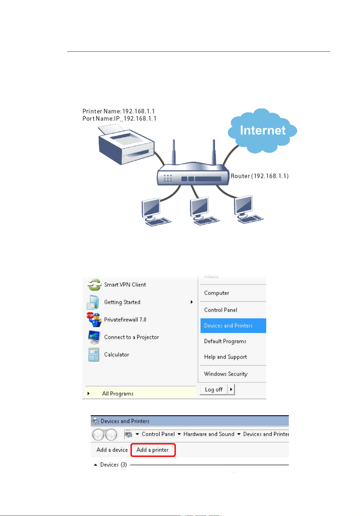
You can install a printer onto the router for sharing printing. All the PCs connected this router
can print documents via the router. The example provided here is made ba sed on Windows 7.
For other Windows system, please visit www.DrayTek.com.
Before using it, please follow the steps below to configure settings for connected computers
(or wireless clients).
1. Connect the printer with the router through USB/parallel port.
2. Open All Programs>>Getting Started>>Devices and Printers.
3. Click Add a printer.
16
Vigor2927 Series User’s Guide
Page 31
7
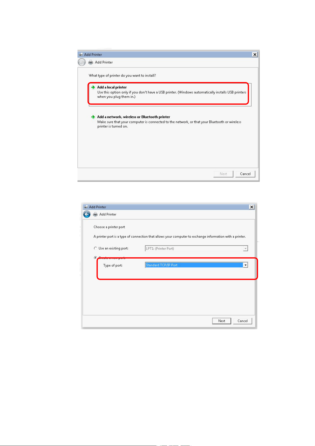
4. A dialog will appear. Click Add a local printer and click Next.
5. In this dialog, choose Create a new port. In the field of Type of port, use the drop down
list to select Standard TCP/IP Port. Then, click Next.
Vigor2927 Series User’s Guide
1
Page 32
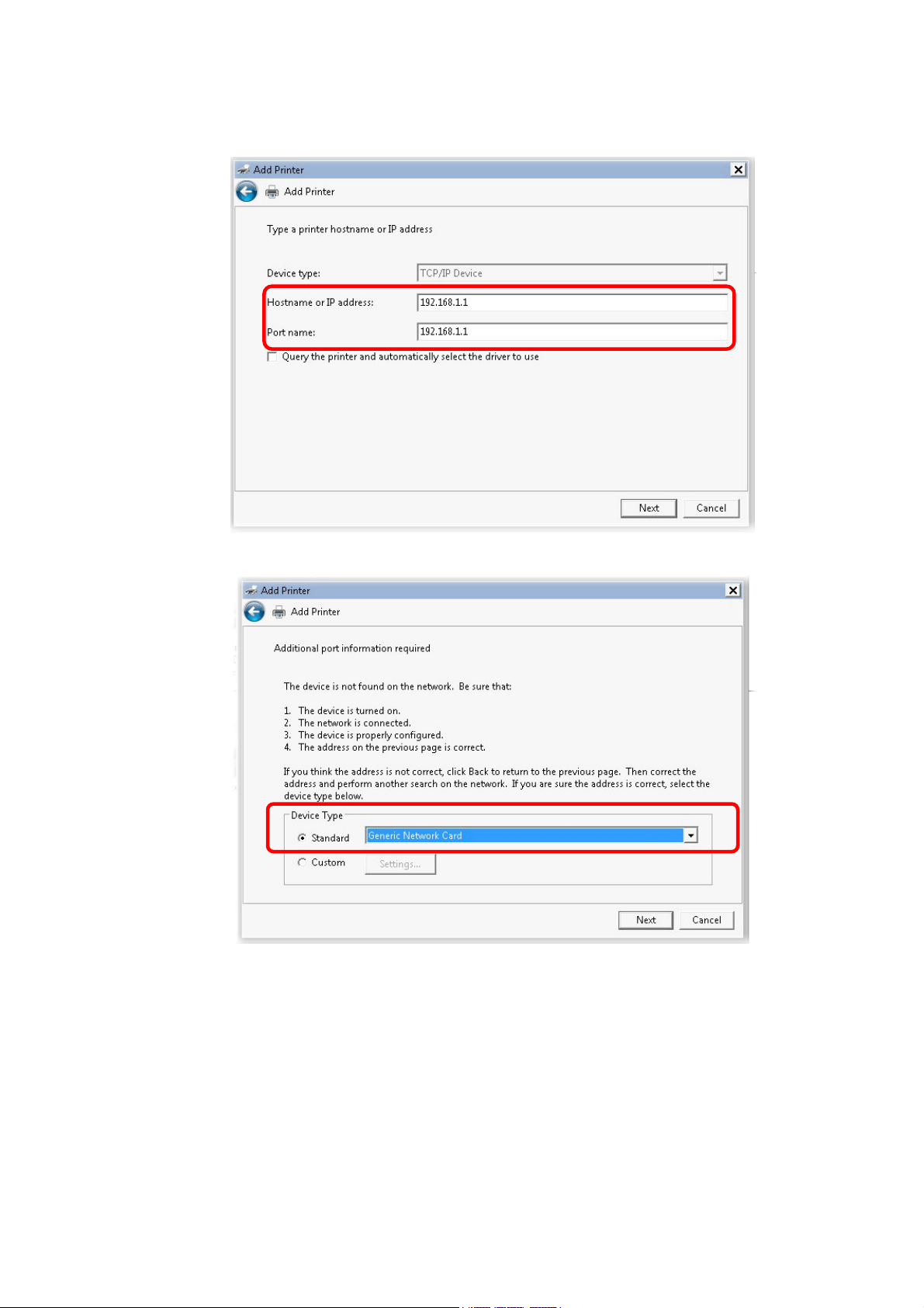
6. In the following dialog, type 192.168.1.1 (router’s LAN IP) in the field of Hostname or
IP Address and type 192.168.1.1 as the Port name. Then, click Next.
7. Click Standard and choose Generic Network Card.
18
Vigor2927 Series User’s Guide
Page 33
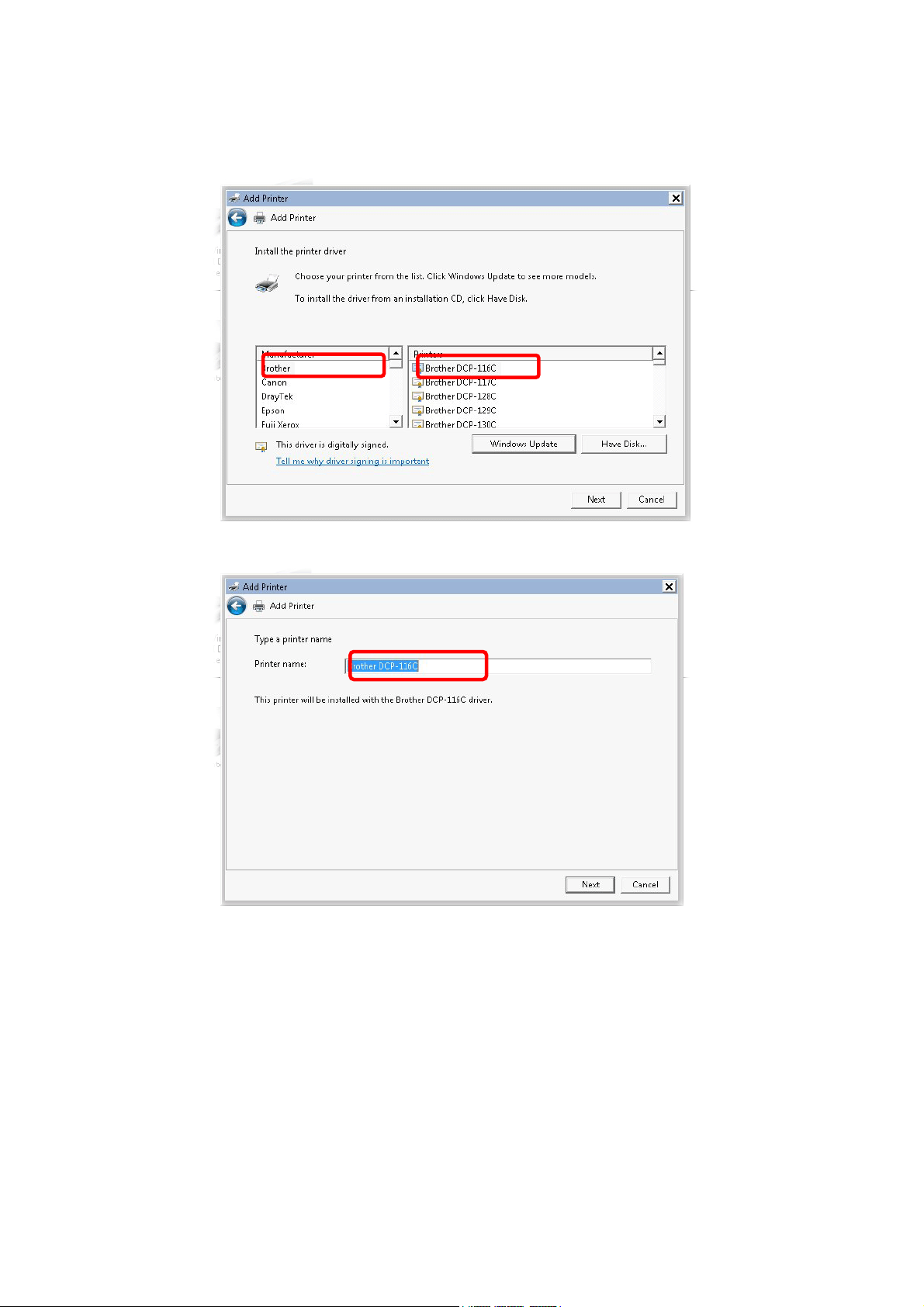
8. Now, your system will ask you to choose right name of the printer that you installed onto
the router. Such step can make correct driver loaded onto your PC. When you finish the
selection, click Next.
9. Type a name for the chosen printer. Click Next.
Vigor2927 Series User’s Guide
19
Page 34
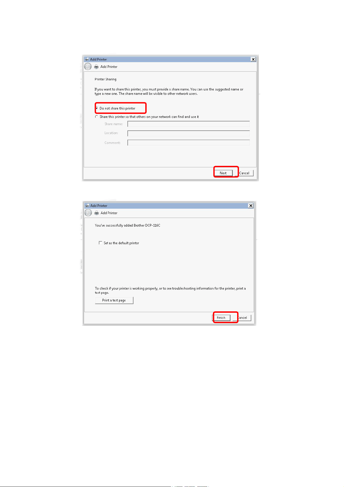
10. Choose Do not share this printer and click Next.
11. Then, in the following dialog, click Finish.
20
Vigor2927 Series User’s Guide
Page 35
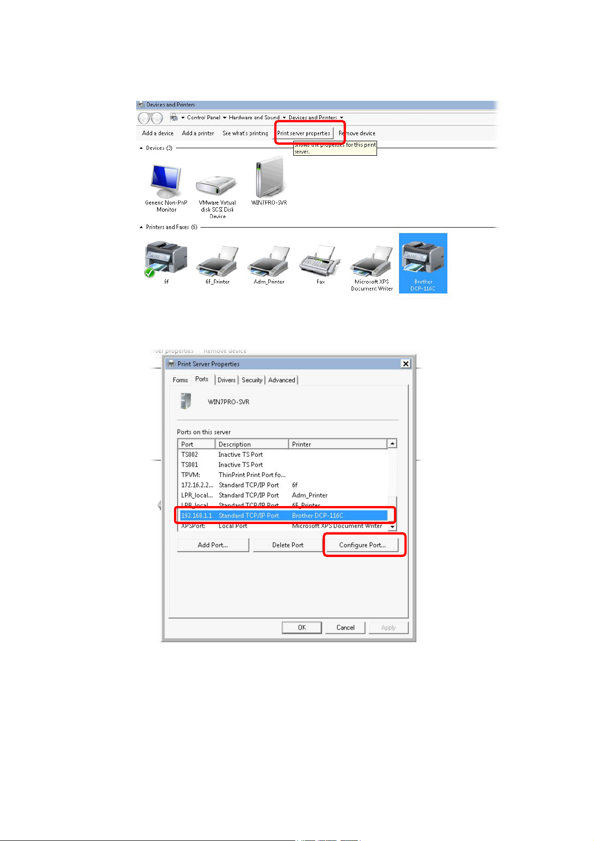
12. The new printer has been added and displayed under Printers and Faxes. Click the new
printer icon and click Printer server properties.
13. Edit the property of the new printer you have added by clicking Configure Port.
Vigor2927 Series User’s Guide
21
Page 36
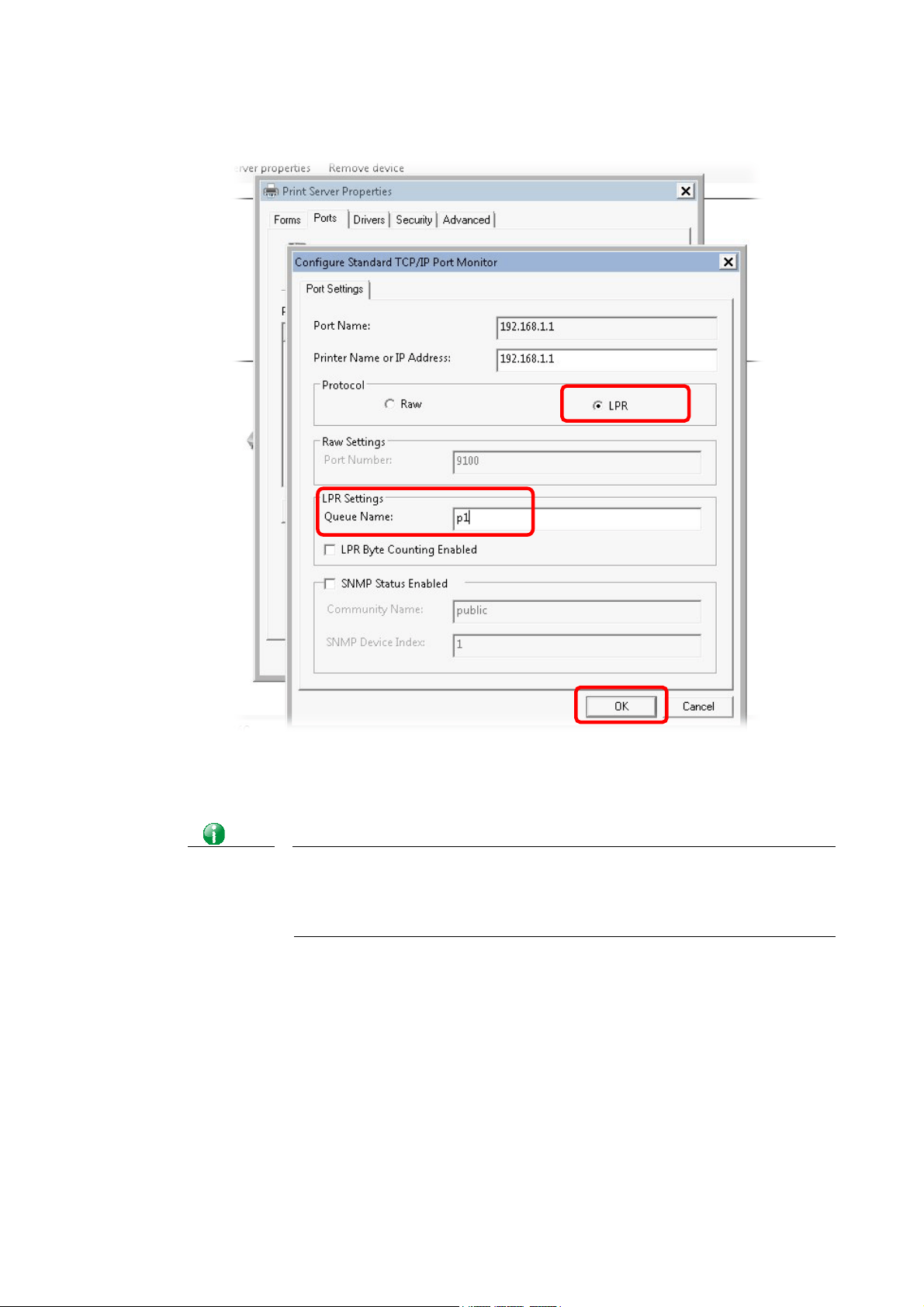
14. Select "LPR" on Protocol, type p1 (number 1) as Queue Name. Then click OK. Next
please refer to the red rectangle for choosing the correct protocol and LPR name.
The printer can be used for printing now. Most of the printers with different manufacturers
are compatible with vigor router.
Info
Some printers with the fax/scanning or other additional functions are not
supported.
Vigor router supports printing request from computers via LAN p orts but
not WAN port.
22
Vigor2927 Series User’s Guide
Page 37
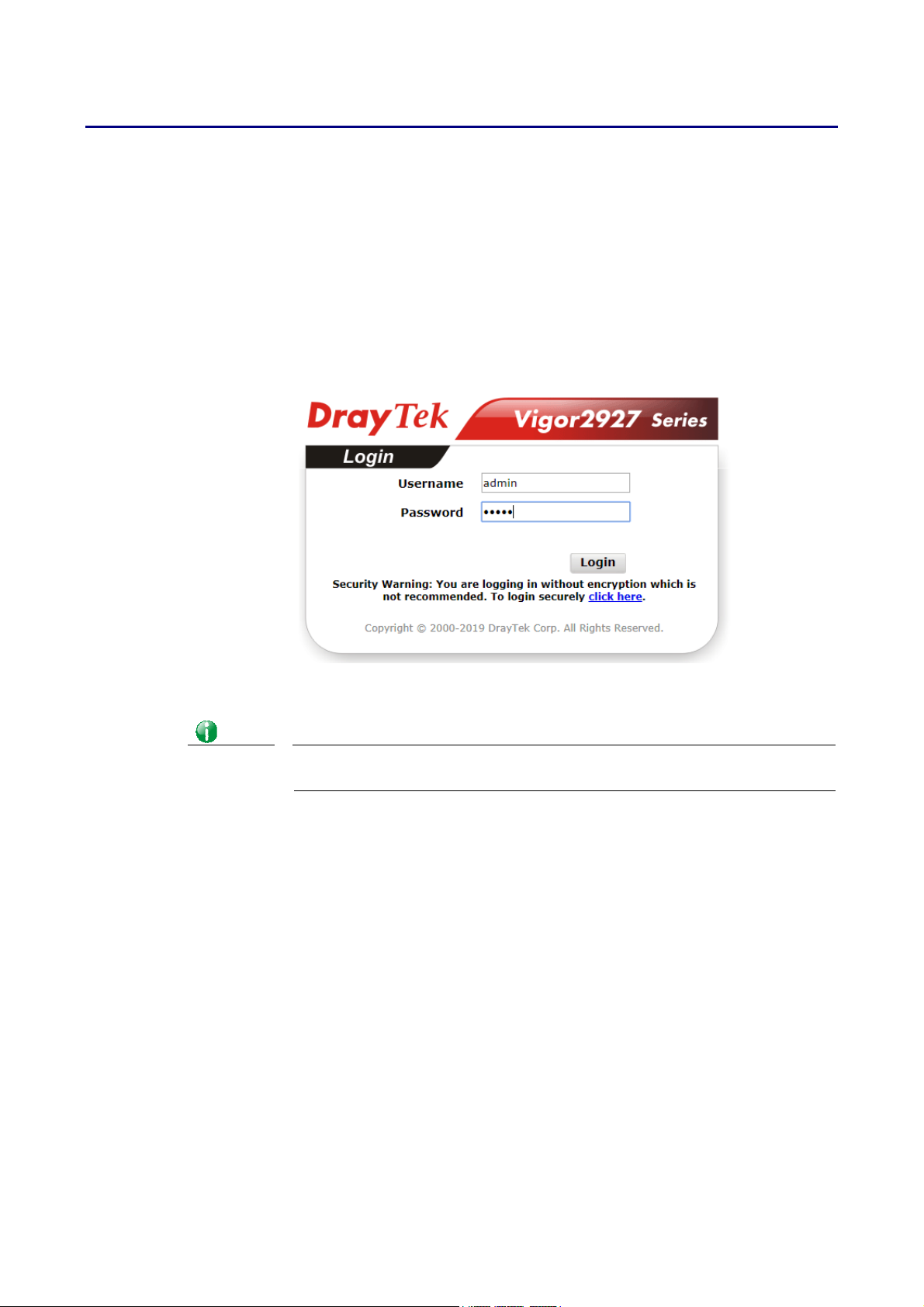
II--33 AAcccceessssiinngg WWeebb PPaaggee
1. Make sure your PC connects to the router correctly.
You may either simply set up your computer to get IP dynamically from the router or set
up the IP address of the computer to be the same subnet as the default IP address of
Vigor router 192.168.1.1. For the detailed information, please refer to the later
section - Trouble Shooting of the guide.
2. Open a web browser on your PC and type http://192.168.1.1. The following window
will be open to ask for username and password.
3. Please type “admin/admin” as the Username/Password and click Login.
Info
If you fail to access to the web configuration, please go to “Trouble
Shooting” for detecting and solving your problem.
Vigor2927 Series User’s Guide
23
Page 38
4
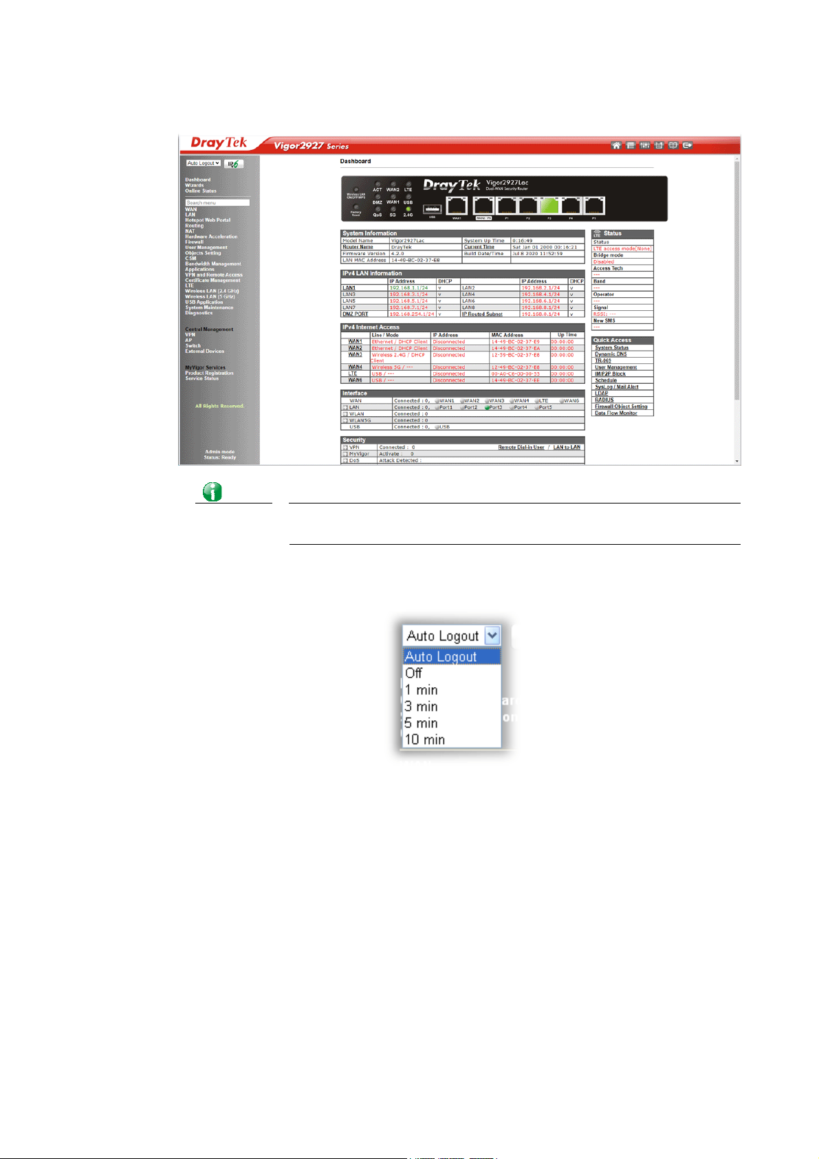
4. Now, the Main Screen will appear. Take Vigor2927ac as an example.
Info
5. The web page can be logged out according to the chosen condition. The default setting
is Auto Logout, which means the web configuration system will logout after 5 minutes
without any operation. Change the setting for your necessity.
The home page will be different slightly in accordance with the type of
the router you have.
2
Vigor2927 Series User’s Guide
Page 39
II--44 CChhaannggiinngg PPaasssswwoorrdd
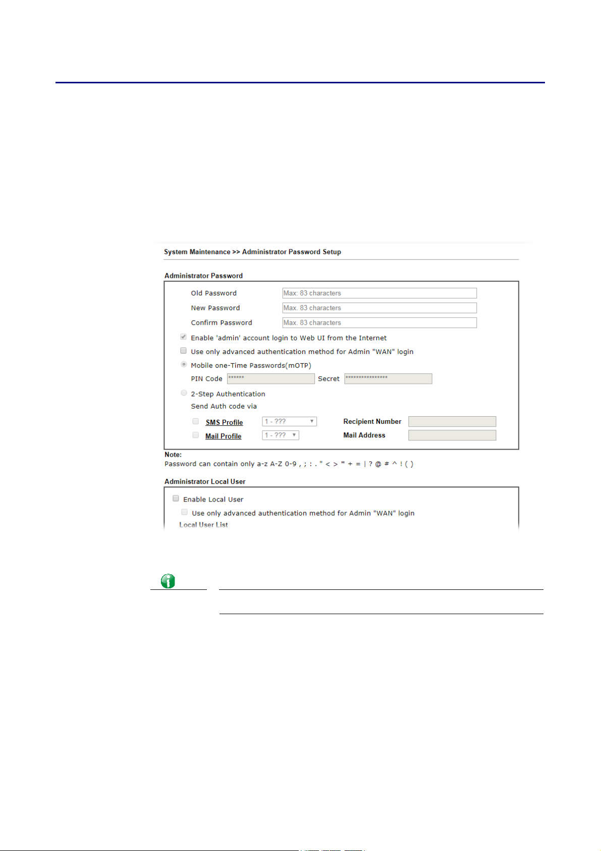
Please change the password for the original security of the router.
1. Open a web browser on your PC and type http://192.168.1.1. A pop-up window will
open to ask for username and password.
2. Please type “admin/admin” as Username/Password for acce ssing into the web user
interface with admin mode.
3. Go to System Maintenance page and choose Administrator Password.
4. Enter the login password (the default is “admin”) on the field of Old Password. Type
New Password and Confirm Password. Then click OK to continue.
Info
Vigor2927 Series User’s Guide
The maximum length of the password you can set is 23 characters.
25
Page 40
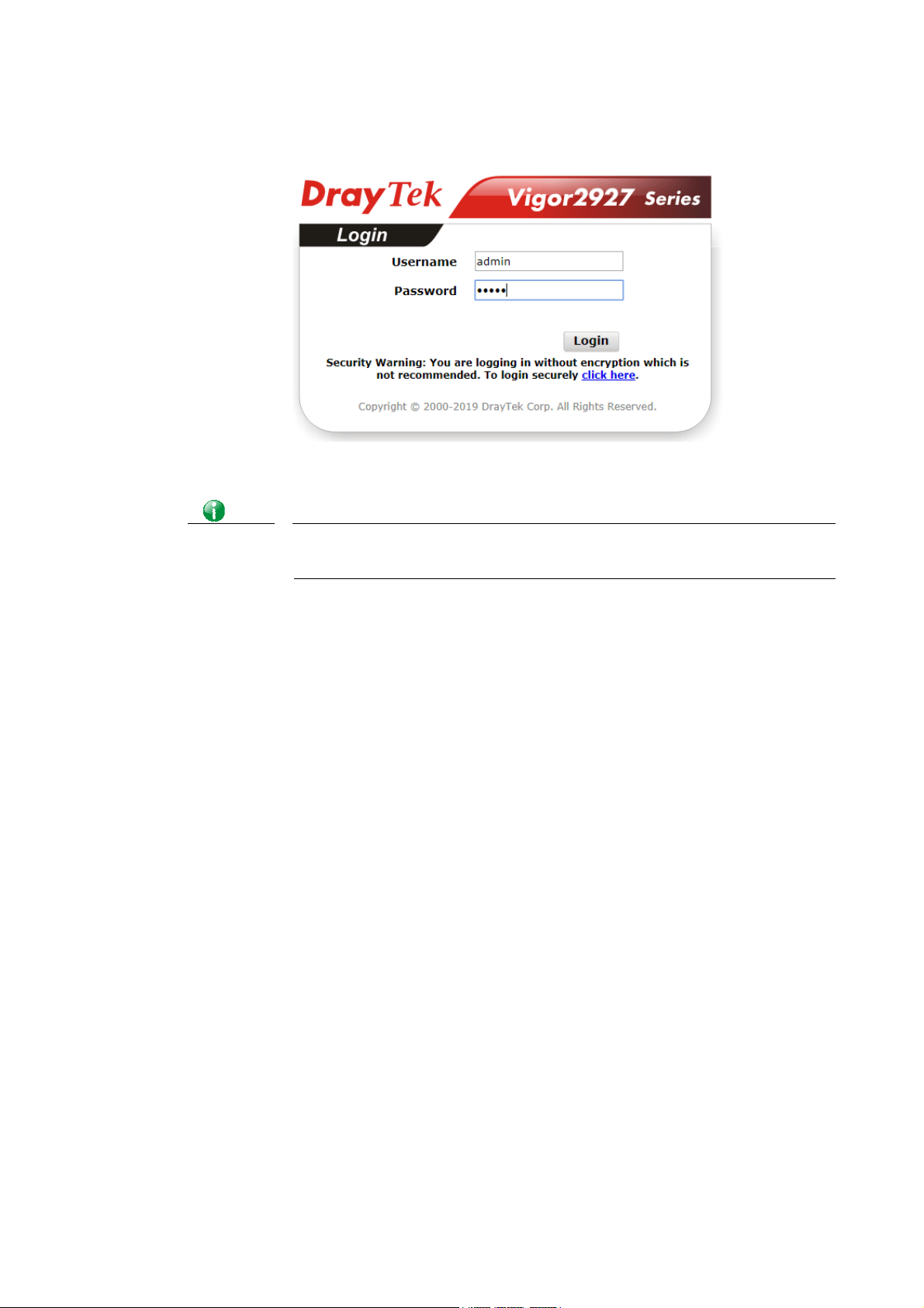
5. Now, the password has been changed. Next time, use the new password to access the
Web user interface for this router.
Info
Even the password is changed, the Username for logging onto the web user
interface is still “admin”.
26
Vigor2927 Series User’s Guide
Page 41
7
II--55 DDaasshhbbooaarrdd
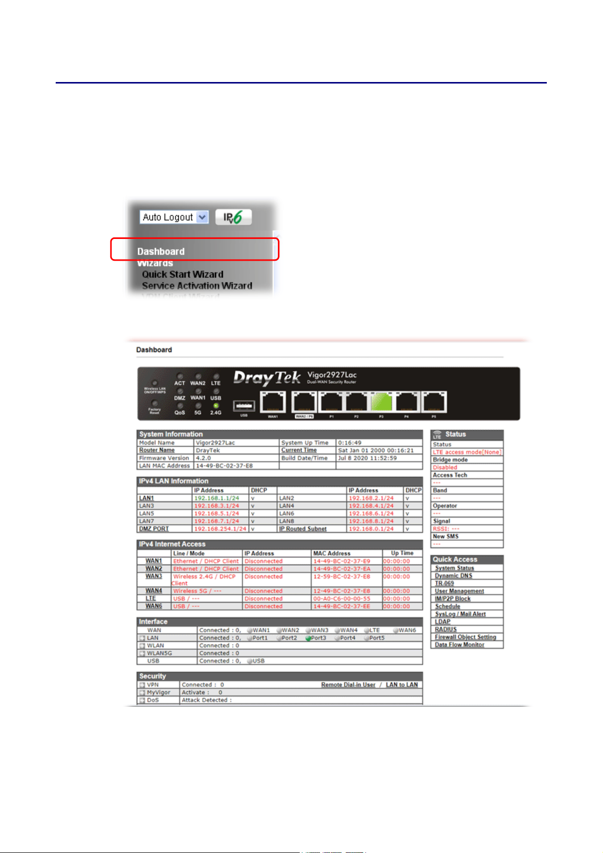
Dashboard shows the connection status including System Information, IPv4 In ternet Access,
IPv6 Internet Access, Interface (physical connection), Security and Quick Access.
Click Dashboard from the main menu on the left side of the main page.
A web page with default selections will be displayed on the screen. Refer to the following
figure:
Vigor2927 Series User’s Guide
2
Page 42
II--55--11 VViirrttuuaall PPaanneell
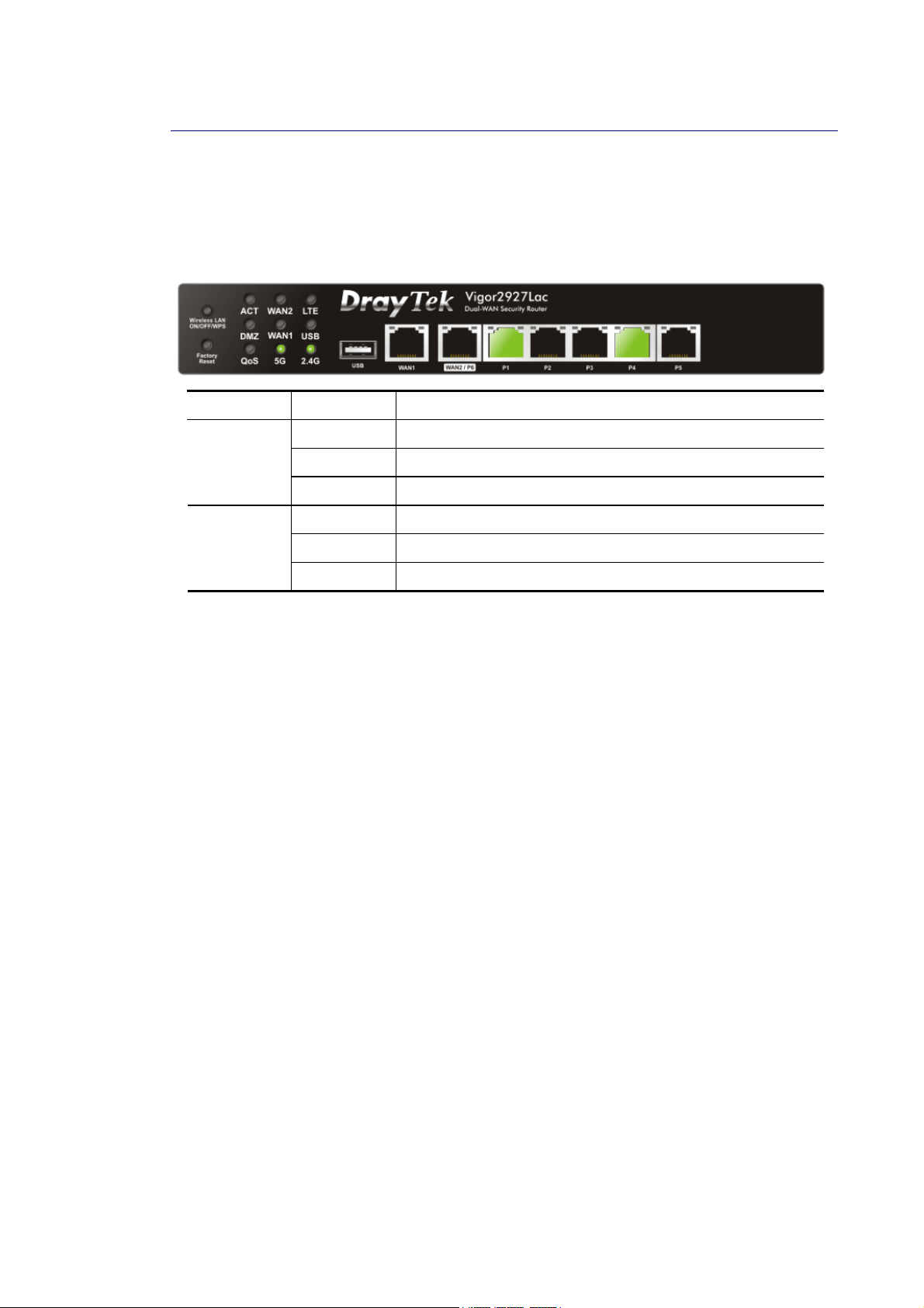
On the top of the Dashboard, a virtual panel (simulating the physical panel of the router)
displays the physical interface connection. It will be refreshed every five seconds. When you
move and click the mouse cursor on LEDs (except ACT), USB ports, WAN2/P6, or LAN1 – LAN5
(P1~P5), related web setting page will be open for you to configure if required.
Port Color Description
WAN2/P6
LAN
1 ~ 5
Black WAN2 port is disconnected.
Green WAN2 port is connected at 1 Gbps.
Orange WAN2 port is connected at 10/100 Mbps.
Black LAN port is disconnected.
Green LAN port is connected at 1 Gbps.
Orange LAN port is connected at 10/100 Mbps.
For detailed information about the LED display, refer to I-1-1 LED Indicators and
Connectors.
28
Vigor2927 Series User’s Guide
Page 43
II--55--22 NNaammee wwiitthh aa LLiinnkk
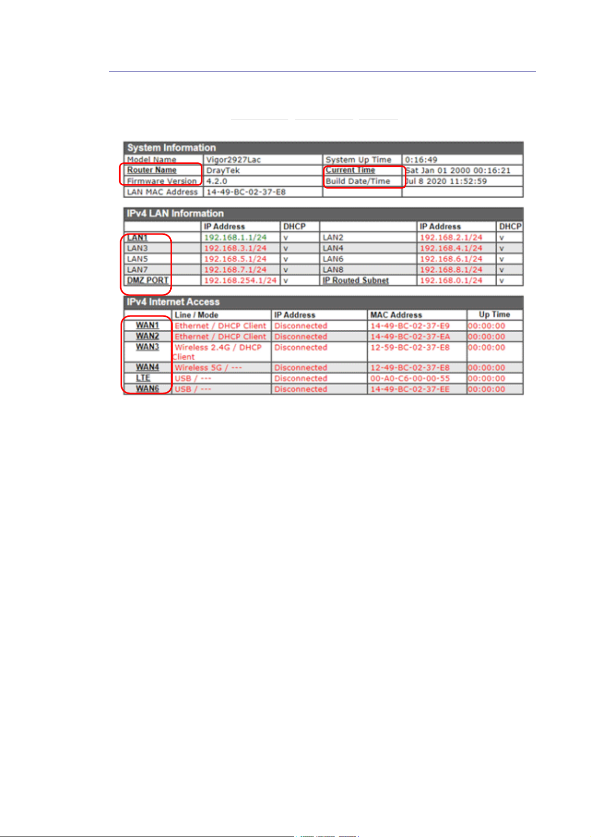
A name with a link (e.g., Router Name, Current Time, WAN1~6 and etc.) below means you can
click it to open the configuration page for modification.
Vigor2927 Series User’s Guide
29
Page 44
II--55--33 QQuuiicckk AAcccceessss ffoorr CCoommmmoonn UUsseedd MMeennuu
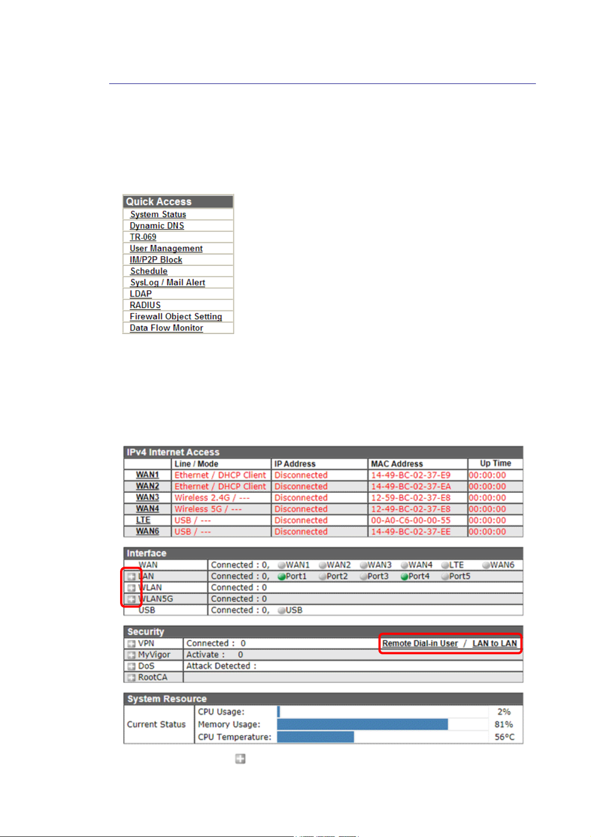
All the menu items can be accessed and arranged orderly on the left side of the main page for
your request. However, some important and common used menu items which can be
accessed in a quick way just for convenience.
Look at the right side of the Dashboard. You will find a group of common used functions
grouped under Quick Access.
The function links of System Status, Dynamic DDNS, TR-069, User Management, IM/P2P Block,
Schedule, Syslog/Mail Alert, LDAP, RADIUS, Firewall Object Setting and Data Flow Monitor are
displayed here. Move your mouse cursor on any one of the links and click on it. The
corresponding setting page will be open immediately.
In addition, quick access for VPN security settings such as Remote Dial-in User and LAN to
LAN are located on the bottom of this page. Scroll down the page to find them and use them
if required.
Note that there is a plus (
VPN connection(s) used presently.
30
) icon located on the left side of VPN/LAN. Click it to review the
Vigor2927 Series User’s Guide
Page 45
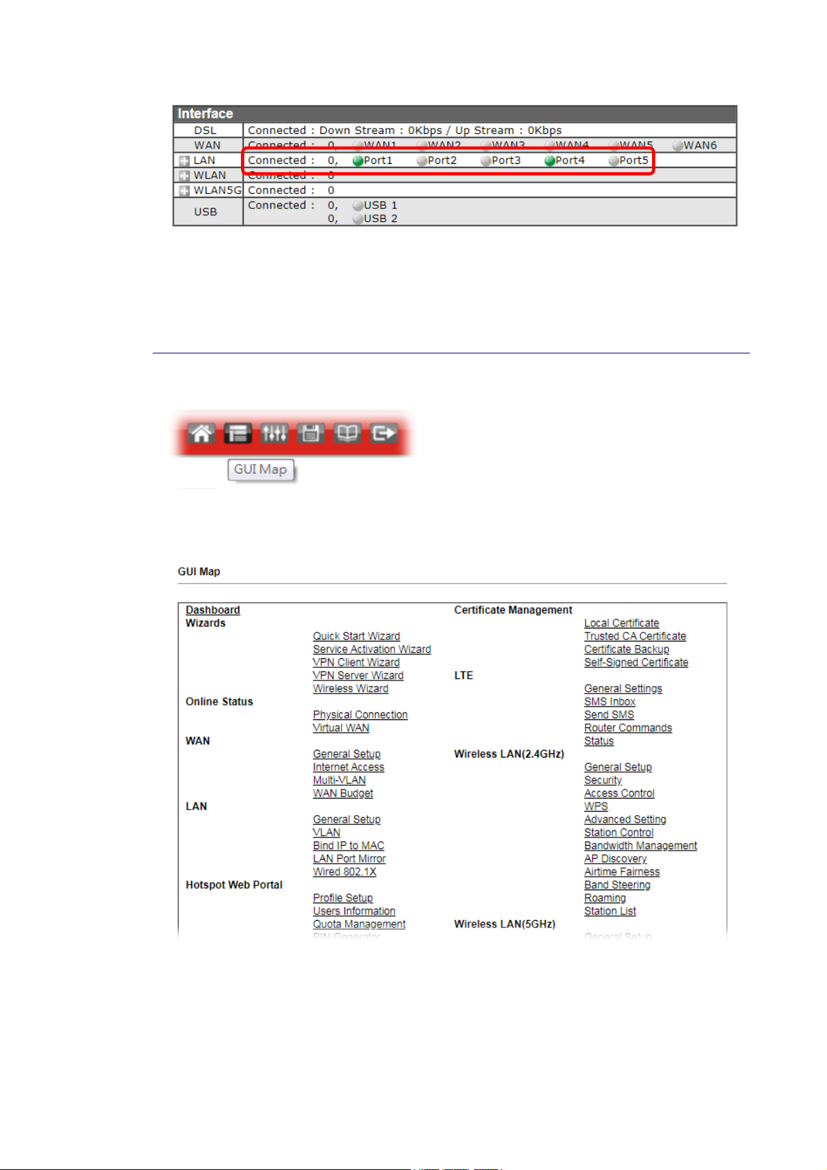
Host connected physically to the router via LAN port(s) will be displayed with green circles in
the field of Connected.
All of the hosts (including wireless clients) displayed with Host ID, IP Address and MAC address
indicates that the traffic would be transmitted through LAN port(s) and then the WAN port.
The purpose is to perform the traffic monitor of the host(s).
II--55--44 GGUUII MMaapp
All the functions the router supports are listed with table clearly in this page. Users can click
the function link to access into the setting page of the function for detailed configuration.
Click the icon on the top of the main screen to display all the functions.
Vigor2927 Series User’s Guide
31
Page 46
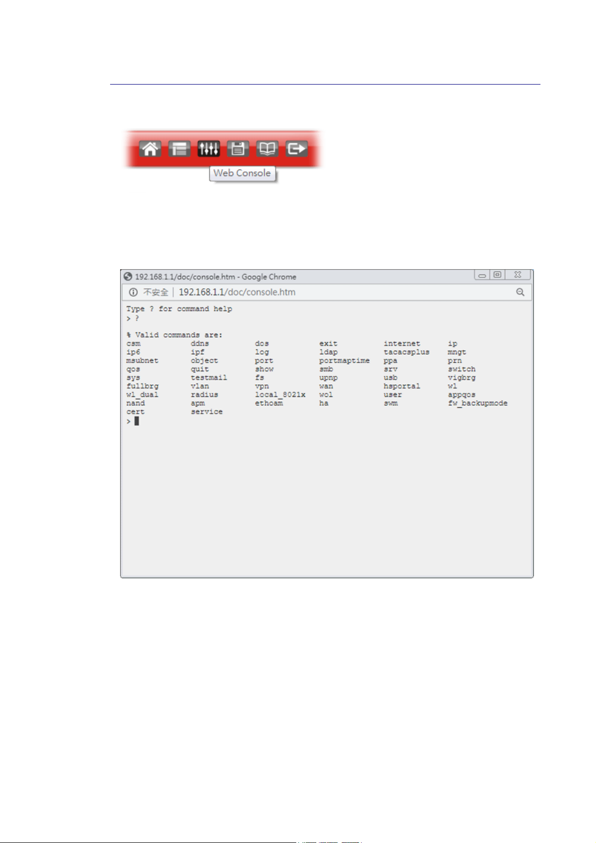
II--55--55 WWeebb CCoonnssoollee
It is not necessary to use the telnet command via DOS prompt. The changes made by using
web console have the same effects as modified through web user interface. The
functions/settings modified under Web Console also can be reviewed on the web user
interface.
Click the Web Console icon on the top of the main screen to open the following screen.
32
Vigor2927 Series User’s Guide
Page 47
II--55--66 CCoonnffiigg BBaacckkuupp
There is one way to store current used settings quickly by clicking the Config Backup icon. It
allows you to backup current settings as a file. Such configuration file can be restored by
using System Maintenance>>Configuration Backup.
II--55--77 LLooggoouutt
Click this icon to exit the web user interface.
Vigor2927 Series User’s Guide
33
Page 48
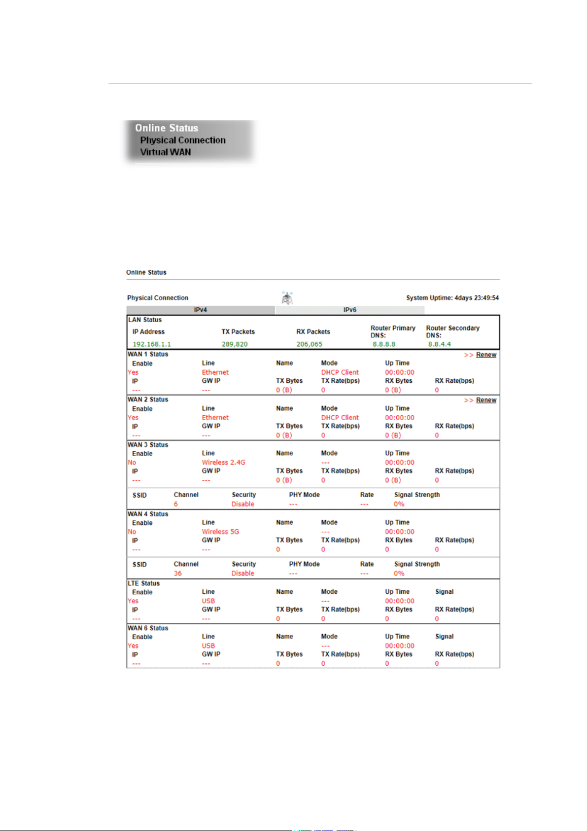
4
II--55--88 OOnnlliinnee SSttaattuuss
II--55--88--11 PPhhyyssiiccaall CCoonnnneeccttiioonn
Such page displays the physical connection status such as LAN connection status, WAN
connection status, and so on.
PPhhyyssiiccaall CCoonnnneeccttiioonn ffoorr IIPPvv44 PPrroottooccooll
3
Vigor2927 Series User’s Guide
Page 49
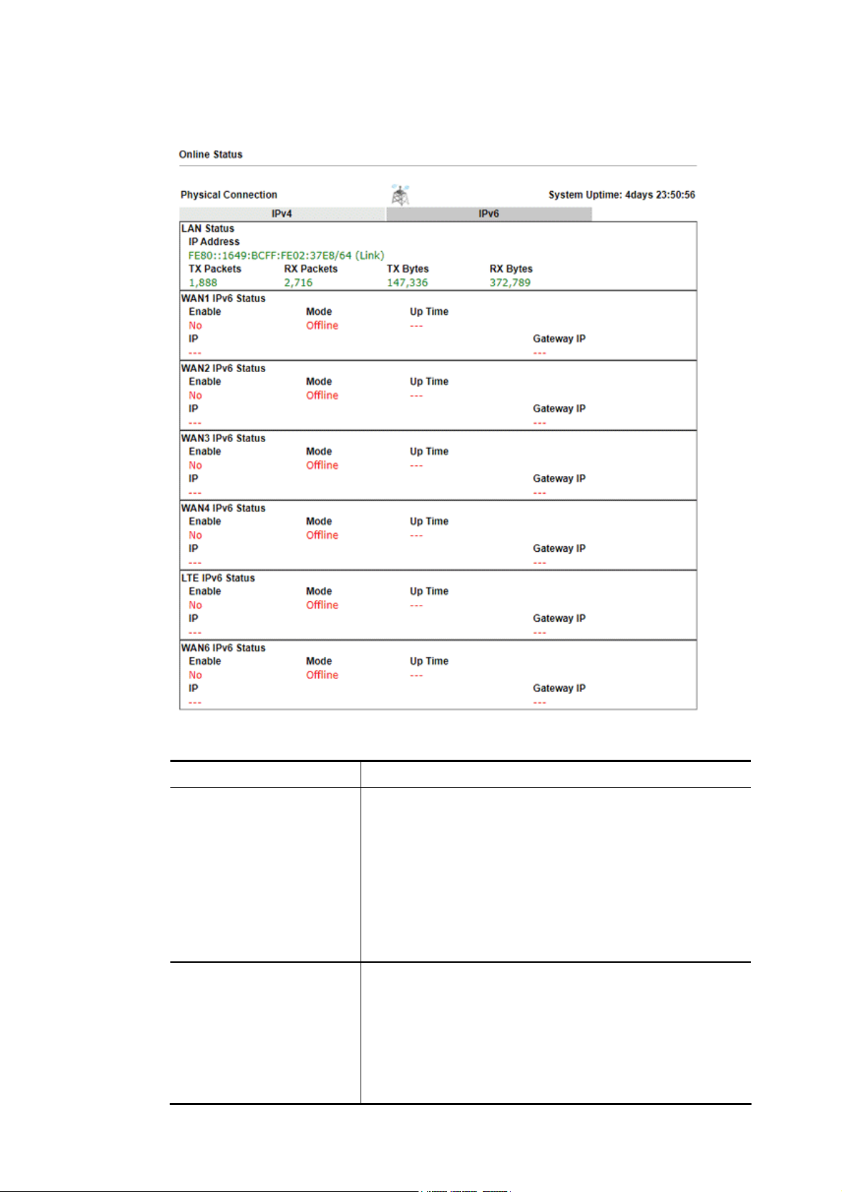
PPhhyyssiiccaall CCoonnnneeccttiioonn ffoorr IIPPvv66 PPrroottooccooll
Detailed explanation (for IPv4) is shown below:
Item Description
LAN Status Primary DNS-Displays the primary DNS server address for
WAN interface.
Secondary DNS -Displays the secondary DNS server address
for WAN interface.
IP Address-Displays the IP address of the LAN interface.
TX Packets-Displays the total transmitted packets at the
LAN interface.
RX Packets-Displays the total received packets at the LAN
interface.
WAN1/WAN2/WAN3
/WAN4/WAN5/WAN6
Status
Enable – Yes in red means such interface is available but
not enabled. Yes in green means such interface is enabled.
Mode - Displays the type of WAN connection (e.g., PPPoE).
Up Time - Displays the total uptime of the interface.
IP - Displays the IP address of the WAN interface.
GW IP - Displays the IP address of the default gateway.
TX Packets - Displays the total transmitted packets at the
Vigor2927 Series User’s Guide
35
Page 50

Item Description
WAN interface.
TX Rate - Displays the speed of transmitted octets at the
WAN interface.
RX Packets - Displays the total number of received packets
at the WAN interface.
RX Rate - Displays the speed of received octets at the WAN
interface.
Detailed explanation (for IPv6) is shown below:
Item Description
LAN Status IP Address- Displays the IPv6 address of the LAN interface..
TX Packets-Displays the total transmitted packets at the LAN
interface.
RX Packets-Displays the total received packets at the LAN
interface.
TX Bytes - Displays the speed of transmitted octets at the
LAN interface.
RX Bytes - Displays the speed of received octets at the LAN
interface.
WAN IPv6 Status Enable – No in red means such interface is available but not
enabled. Yes in green means such inte rface is enabled. No in
red means such interface is not available.
Mode - Displays the type of WAN connection (e.g., TSPC).
Up Time - Displays the total uptime of the interface.
IP - Displays the IP address of the WAN interface.
Gateway IP - Displays the IP address of the default gateway.
Info
The words in green mean that the WAN connection of that interface is
ready for accessing Internet; the words in red mean that the WAN
connection of that interface is not ready for accessing Internet.
36
Vigor2927 Series User’s Guide
Page 51

7
II--55--88--22 VViirrttuuaall WWAANN
Such page displays the virtual WAN connection information.
Virtual WAN are used by TR-069 management, VoIP service and so on.
The field of Application will list the purpose of such WAN connection.
Vigor2927 Series User’s Guide
3
Page 52
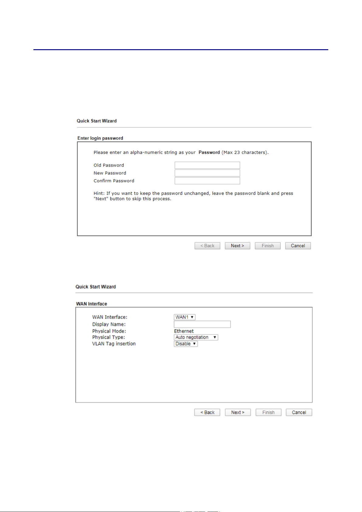
II--66 QQuuiicckk SSttaarrtt WWiizzaarrdd
Quick Start Wizard can help you to deploy and use the router easily and quickly.
Go to Wizards>>Quick Start Wizard. The first screen of Quick Start Wizard is entering login
password. After typing the password, please click Next.
On the next page as shown below, please select the WAN interface that you use. If Ethernet
interface is used, please choose WAN1/WAN2; if 3G USB modem is used, please choose WAN3
or WAN4. Then click Next for next step.
WAN1, WAN2, WAN3, WAN4, WAN5 and WAN6 will bring up different configuration page.
Refer to the following for detailed information.
38
Vigor2927 Series User’s Guide
Page 53
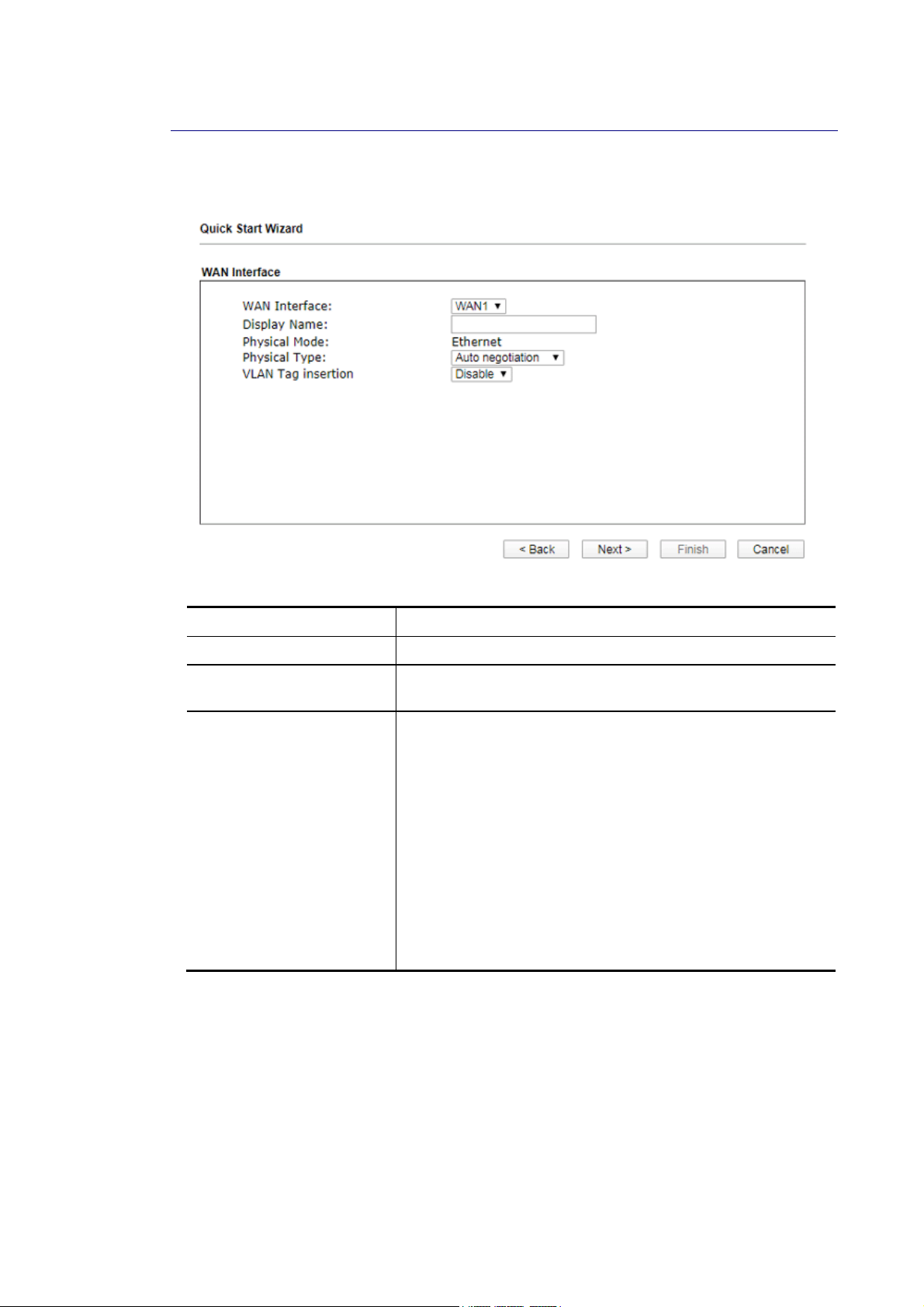
II--66--11 FFoorr WWAANN11//WWAANN22 ((EEtthheerrnneett))
WAN2 can be configured for physical mode of Ethernet.
Available settings are explained as follows:
Item Description
Display Name Enter a name for the router.
Physical Type This setting is available when Ethernet is selected as
Physical Mode. In general, Auto negotiation is suggested.
VLAN Tag insertion The settings configured in this field are available when
Ethernet is selected as Physical Mode.
Disable – Disable the function of VLAN with tag.
Enable – Enable the function of VLAN with tag.
The router will add specific VLAN number to all packets on
the WAN while sending them out.
Please Enter the tag value and specify the priority for the
packets sending by WAN2.
Tag value – Enter the value as the VLAN ID number. The
range is form 0 to 4095.
Priority – Enter the packet priority number for such
VLAN. The range is from 0 to 7.
On the next page as shown below, please select the appropriate Internet access type
according to the information from your ISP. For example, you should select PPPoE mode if the
ISP provides you PPPoE interface. Then click Next for next step.
Vigor2927 Series User’s Guide
39
Page 54
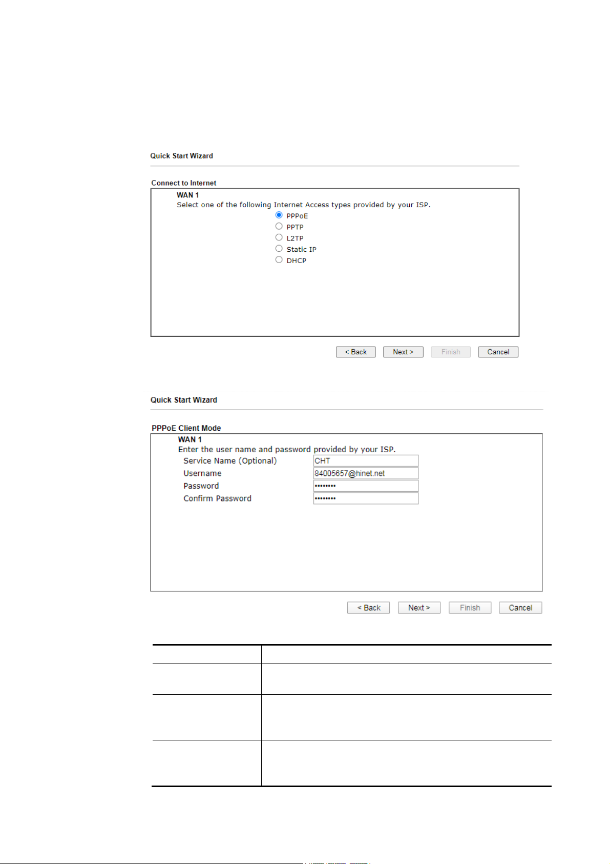
EEtthheerrnneett WWAANN11//22 -- PPPPPPooEE
1. Choose WAN1 as the WAN Interface and choose Ethernet as the Physical Mode. Click
the Next button. The following page will be open for you to specify Internet Access
Type.
2. Click PPPoE as the Internet Access Type. Then click Next to continue.
Available settings are explained as follows:
Item Description
Service Name
(Optional)
Username Assign a specific valid user name provided by the ISP.
Password Assign a valid password provided by the ISP.
40
Enter the description of the specific network service.
Note: The maximum length of the user name you can set is
63 characters.
Note: The maximum length of the password you can set is 62
characters.
Vigor2927 Series User’s Guide
Page 55
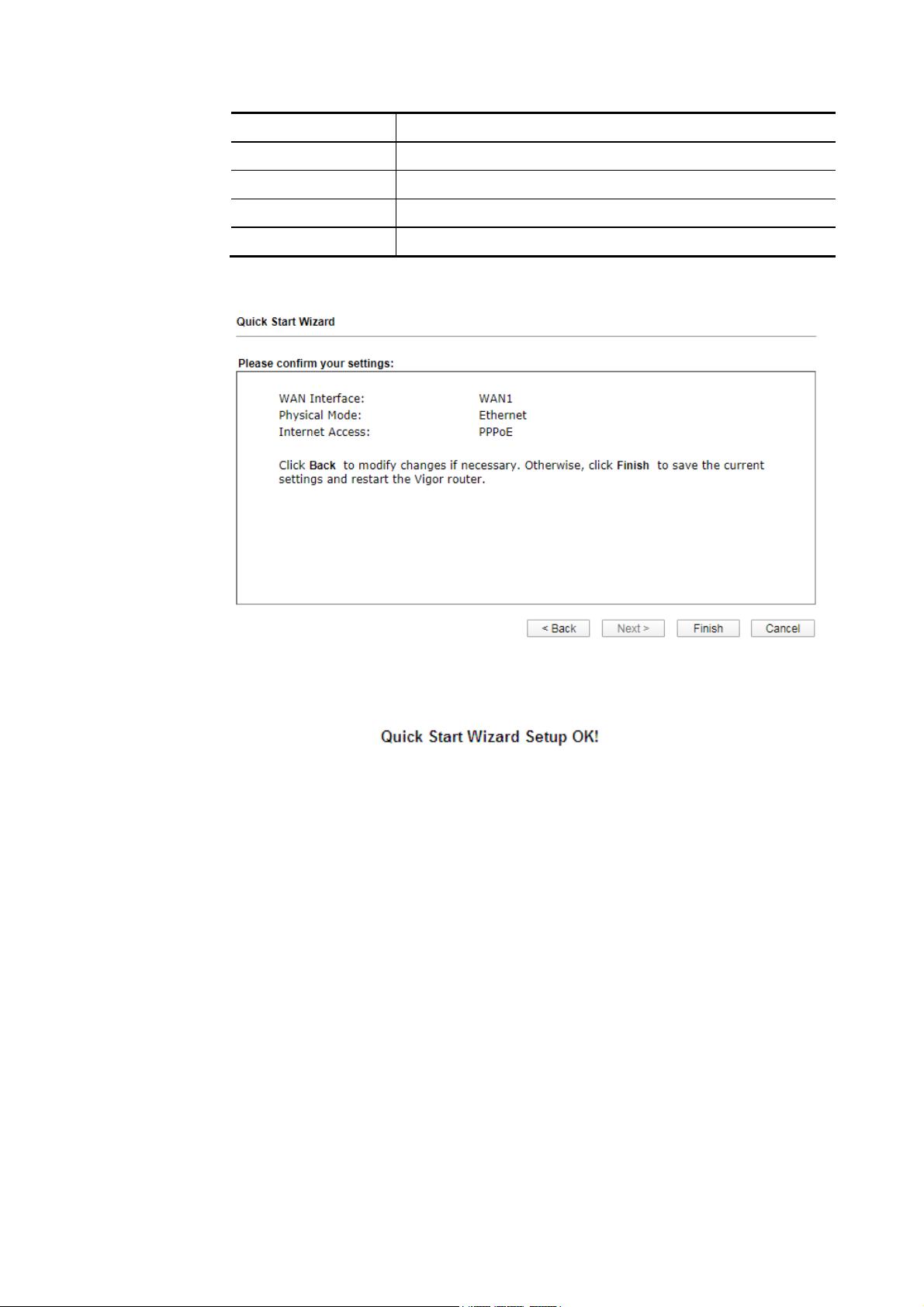
Item Description
Confirm Password Re-enter the password.
Back Click it to return to previous setting page.
Next Click it to get into the next setting page.
Cancel Click it to give up the quick start wizard.
3. Please manually enter the Username/Password provided by your ISP. Click Next for
viewing summary of such connection.
4. Click Finish. A page of Quick Start Wizard Setup OK!!! will appear. Then, the system
status of this protocol will be shown.
5. Now, you can enjoy surfing on the Internet.
Vigor2927 Series User’s Guide
41
Page 56
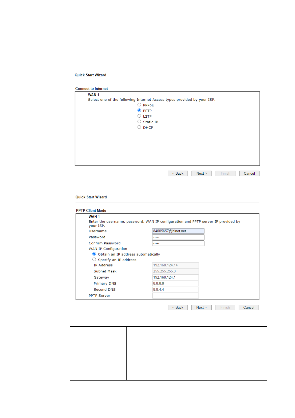
EEtthheerrnneett WWAANN11//22 -- PPPPTTPP//LL22TTPP
1. Choose WAN1 as the WAN Interface and choose Ethernet as the Physical Mode. Click
the Next button. The following page will be open for you to specify Internet Access
Type.
2. Click PPTP/L2TP as the Internet Access Type. Then click Next to continue.
Available settings are explained as follows:
Item Description
Username Assign a specific valid user name provided by the ISP.
Note: The maximum length of the user name you can set is
63 characters.
Password Assign a valid password provided by the ISP.
Note: The maximum length of the password you can set is 62
characters.
42
Vigor2927 Series User’s Guide
Page 57
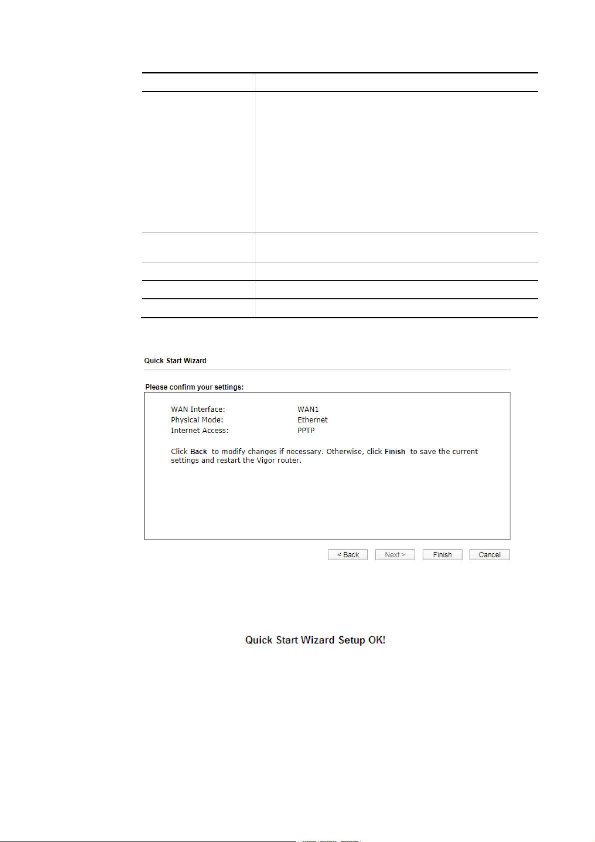
Confirm Password ReEnter the password.
WAN IP Configuration Obtain an IP address automatically – The router will get an
IP address automatically from DHCP server.
Specify an IP address – You have to type relational settings
manually.
IP Address - Enter the IP address.
Subnet Mask – Enter the subnet mask.
Gateway – Enter the IP address of the gateway.
Primary DNS – Enter the primary IP address for the router.
Second DNS – Enter secondary IP address for necessity in the
future.
PPTP Server / L2TP
Enter the IP address of the server.
Server
Back Click it to return to previous setting page.
Next Click it to get into the next setting page.
Cancel Click it to give up the quick start wizard.
3. Please Enter the IP address/mask/gateway information originally provided by your ISP.
Then click Next for viewing summary of such connection.
4. Click Finish. A page of Quick Start Wizard Setup OK!!! will appear. Then, the system
status of this protocol will be shown.
5. Now, you can enjoy surfing on the Internet.
Vigor2927 Series User’s Guide
43
Page 58
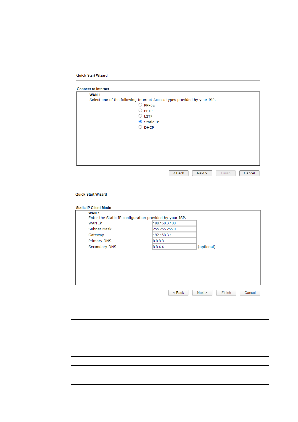
4
EEtthheerrnneett WWAANN11//22 -- SSttaattiicc IIPP
1. Choose WAN1 as the WAN Interface and choose Ethernet as the Physical Mode. Click
the Next button. The following page will be open for you to specify Internet Access
Type.
2. Click Static IP as the Internet Access type. Simply click Next to continue.
Available settings are explained as follows:
Item Description
WAN IP Enter the IP address.
Subnet Mask Enter the subnet mask.
Gateway Enter the IP address of gateway.
Primary DNS Enter the primary IP address for the router.
Secondary DNS Enter the secondary IP address for necessity in the future.
Back Click it to return to previous setting page.
4
Vigor2927 Series User’s Guide
Page 59
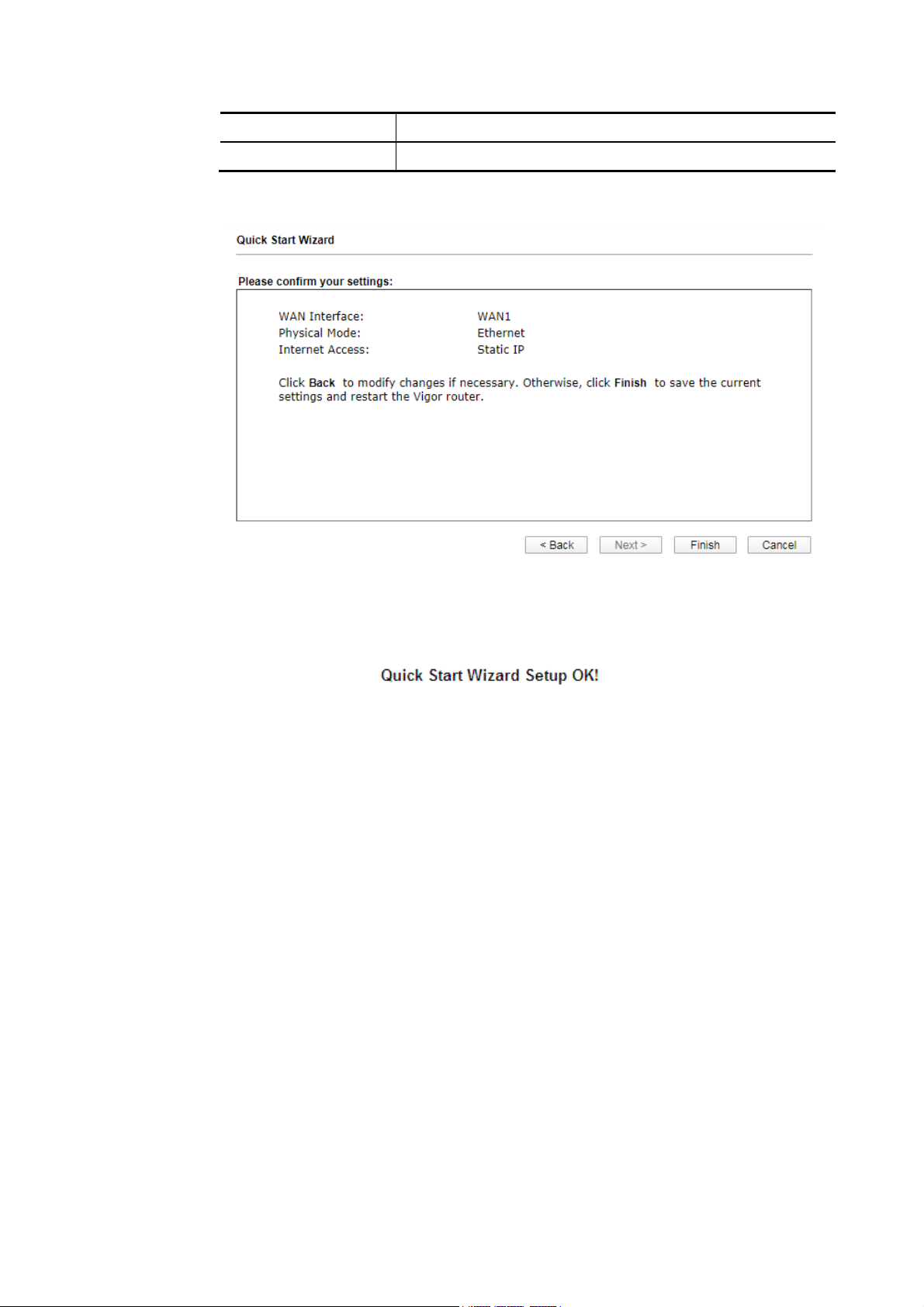
Next Click it to get into the next setting page.
Cancel Click it to give up the quick start wizard.
3. Please Enter the IP address information originally provided by your ISP. Then click Next
for next step.
4. Click Finish. A page of Quick Start Wizard Setup OK!!! will appear. Then, the system
status of this protocol will be shown.
5. Now, you can enjoy surfing on the Internet.
Vigor2927 Series User’s Guide
45
Page 60
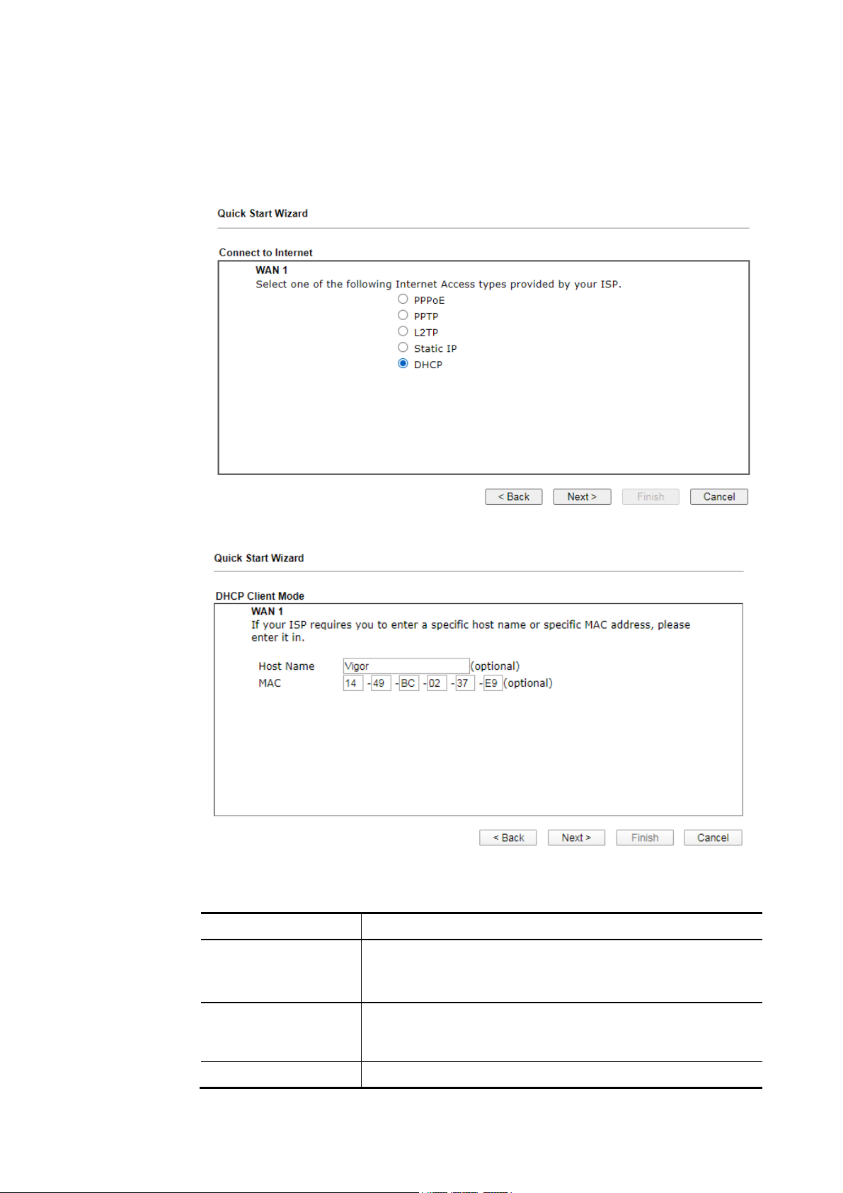
EEtthheerrnneett WWAANN11//22 -- DDHHCCPP
1. Choose WAN1 as the WAN Interface and choose Ethernet as the Physical Mode. Click
the Next button. The following page will be open for you to specify Internet Access
Type.
2. Click DHCP as the Internet Access type. Simply click Next to continue.
Available settings are explained as follows:
Item Description
Host Name Enter the name of the host.
Note: The maximum length of the host name you can set is
39 characters.
MAC Some Cable service providers specify a specific MAC address
for access authentication. In such cases you need to enter
the MAC address.
Back Click it to return to previous setting page.
46
Vigor2927 Series User’s Guide
Page 61
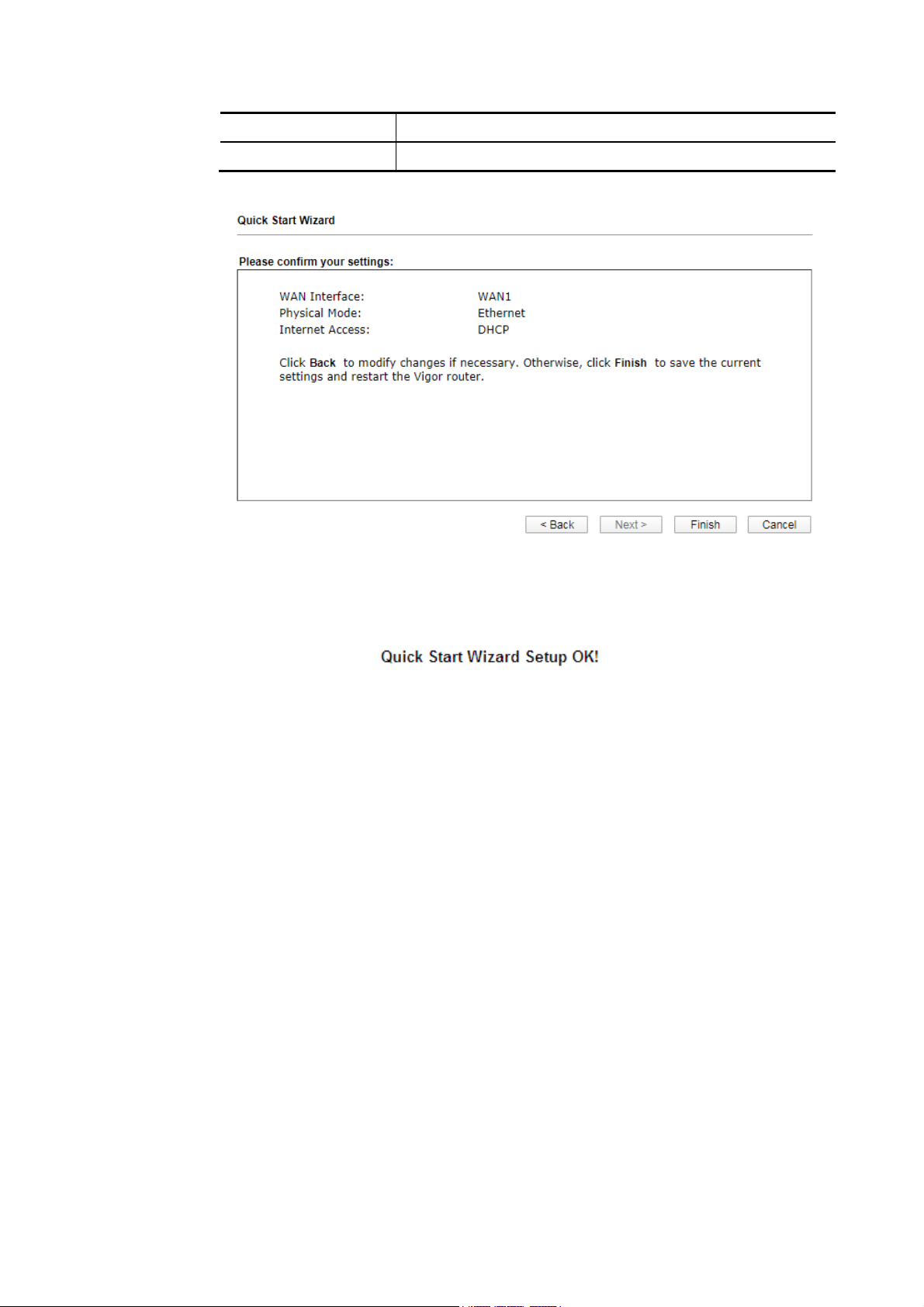
7
Next Click it to get into the next setting page.
Cancel Click it to give up the quick start wizard.
3. After finished the settings above, click Next for viewing summary of such connection.
4. Click Finish. A page of Quick Start Wizard Setup OK!!! will appear. Then, the system
status of this protocol will be shown.
5. Now, you can enjoy surfing on the Internet.
Vigor2927 Series User’s Guide
4
Page 62
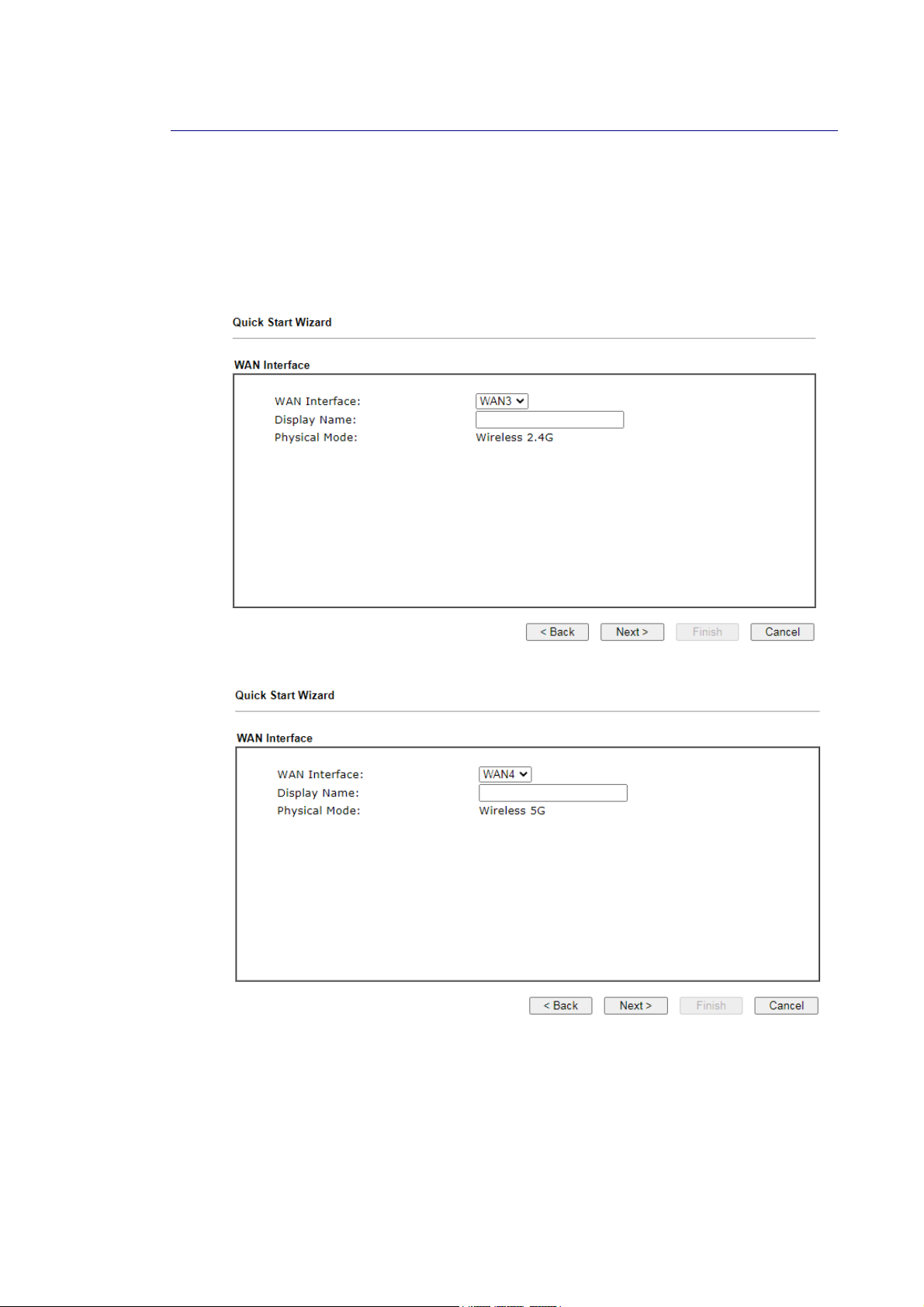
II--66--22 FFoorr WWAANN33//WWAANN44 ((WWiirreelleessss 22..44GG//WWiirreelleessss 55GG))
WAN3/WAN4 shall be used for wireless (2.4G or 5G) connection.
WWiirreelleessss WWAANN33//WWAANN44 -- SSttaattiicc IIPP
1. Choose WAN3/WAN4 as WAN Interface and chooose Wireless 2.4G or Wireless 5G as the
physical mode.
or
48
Vigor2927 Series User’s Guide
Page 63
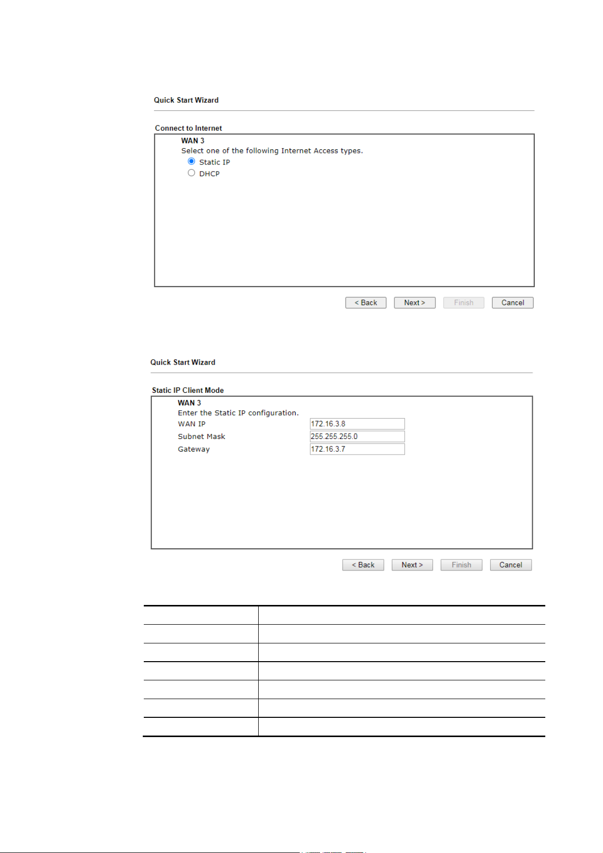
2. Then, click Next for getting the following page.
3. After click Static IP as the Internet Access type, you will get the following page. Enter
the required information and click Next to continue.
Available settings are explained as follows:
Item Description
WAN IP Enter the IP address.
Subnet Mask Enter the subnet mask.
Gateway Enter the IP address of gateway.
Back Click it to return to previous setting page.
Next Click it to get into the next setting page.
Cancel Click it to give up the quick start wizard.
Vigor2927 Series User’s Guide
49
Page 64
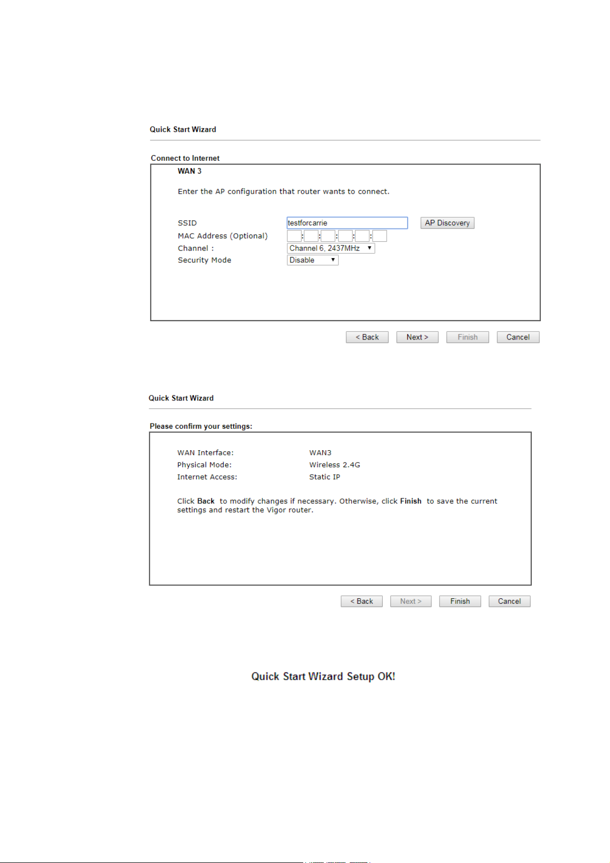
4. From the following page, enter the SSID of an existed AP as the wireless connection
server for this WAN. Or click AP Discovery to find an access point as the server for this
WAN interface. Click Next to continue.
5. Then, a summary of the connection will be shown on the screen.
6. Click Finish. A page of Quick Start Wizard Setup OK!!! will appear. Then, the system
status of this protocol will be shown.
7. Now, you can enjoy surfing on the Internet.
50
Vigor2927 Series User’s Guide
Page 65
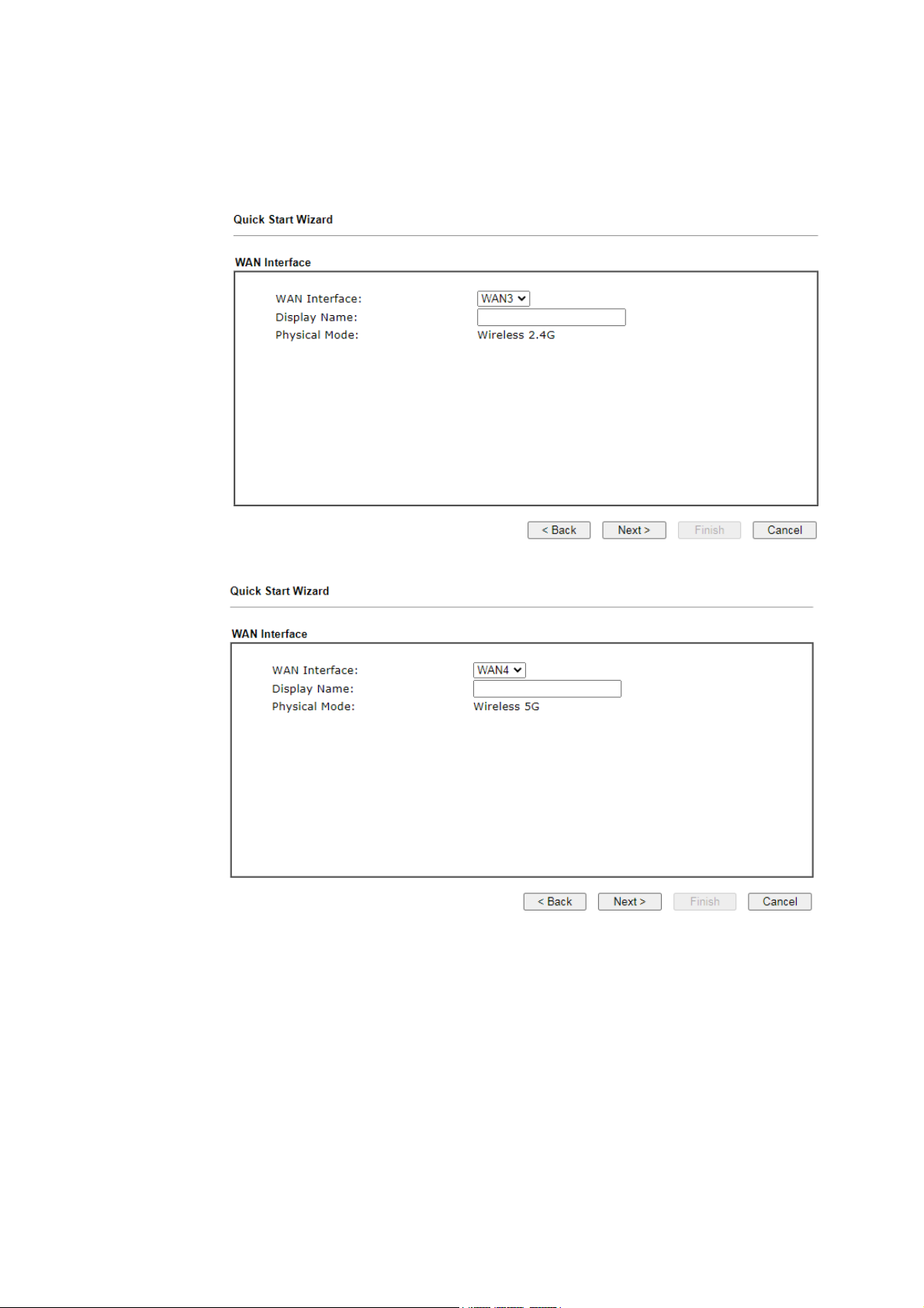
WWiirreelleessss WWAANN33//WWAANN44 -- DDHHCCPP
1. Choose WAN3/WAN4 as WAN Interface and chooose Wireless 2.4G or Wireless 5G as the
physical mode.
or
Vigor2927 Series User’s Guide
51
Page 66
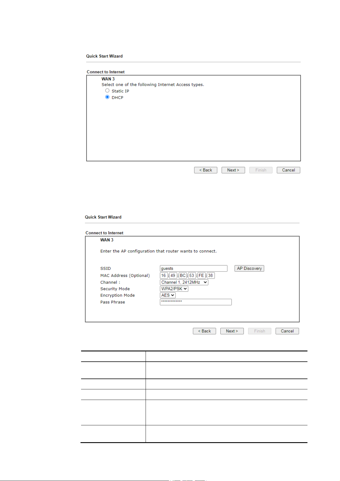
2. Then, click Next for getting the following page.
3. After click DHCP as the Internet Access type, you will get the following page. Eenter the
SSID of an existed AP as the wireless connection server for this WAN. Or click AP
Discovery to find an access point as the server for this WAN interface. Click Next to
continue.
Available settings are explained as follows:
Item Description
SSID Enter the SSID of an existed AP. Or click AP Discovery to find
an access point as the server for this WAN interface
MAC Address Enter the MAC address of an existed AP.
Channel Choose a channel of frequency of the Wireless AP.
Securithy Mode The Router connects to the wireless AP as a WEP, WPA or
WPA2 client.
Select a mode to connect to the Wireless AP.
Encryption Mode WPA/PSK uses TKIP as Encryption Mode. WPA2/PSK uses AES
as Encryption Mode.
52
Vigor2927 Series User’s Guide
Page 67
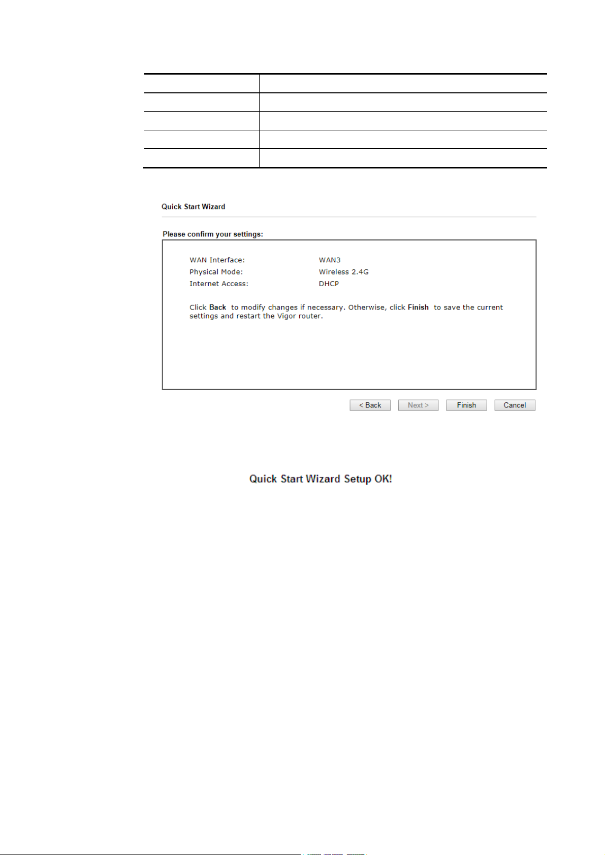
Pass Phrase It is available when WPA/PSK or WPA2/PSK is enabled.
WEP Keys It is available when WEP is enabled.
Back Click it to return to previous setting page.
Next Click it to get into the next setting page.
Cancel Click it to give up the quick start wizard.
4. Then, a summary of the connection will be shown on the screen.
5. Click Finish. A page of Quick Start Wizard Setup OK!!! will appear. Then, the system
status of this protocol will be shown.
6. Now, you can enjoy surfing on the Internet.
Vigor2927 Series User’s Guide
53
Page 68
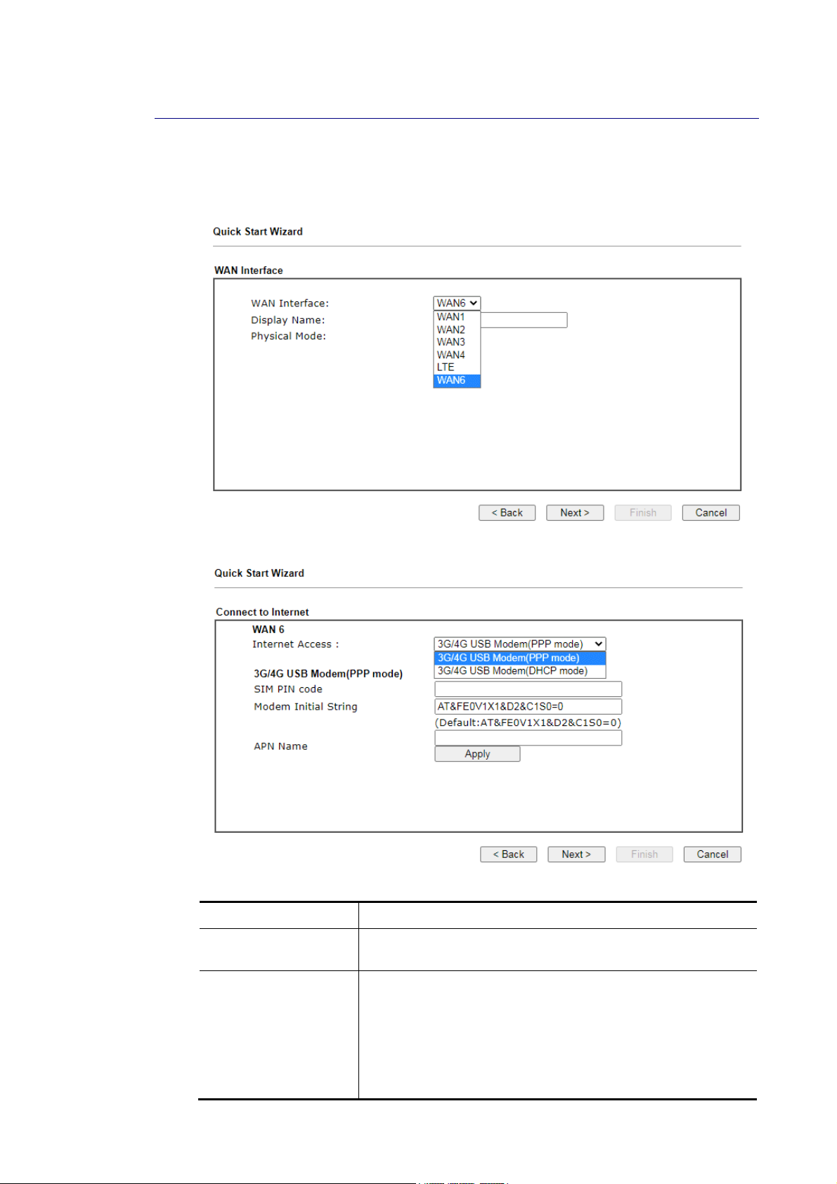
4
II--66--33 FFoorr WWAANN55//WWAANN66 ((UUSSBB))
WAN3/WAN4 is dedicated to physical mode in USB.
1. Choose WAN5/WAN6 as WAN Interface. For "L" model, the WAN5 will be changed as LTE.
2. Then, click Next for getting the following page.
Available settings are explained as follows:
Item Description
Internet Access Choose one of the selections as the protocol of accessing the
internet.
3G/4G USB Modem
(PPP mode)
5
SIM Pin code –Type PIN code of the SIM card that will be used
to access Internet. The maximum length of the pin code you
can set is 15 characters.
Modem Initial String – Such value is used to initialize USB
modem. Please use the default value. If you have any
question, please contact to your ISP. The maximum length of
the string you can set is 47 characters.
Vigor2927 Series User’s Guide
Page 69
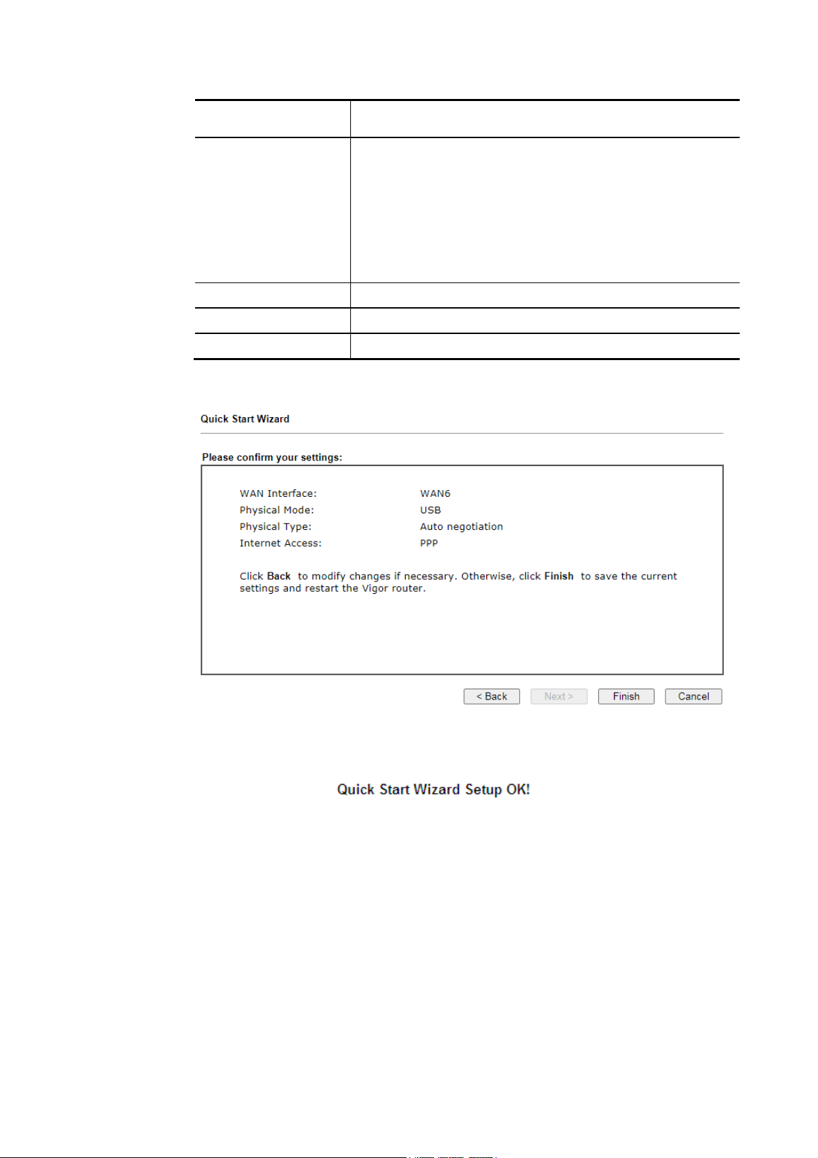
APN Name – APN means Access Point Name which is provided
and required by some ISPs. Enter the name and click Apply.
3G/4G USB Modem
(DHCP mode)
SIM Pin code – Type PIN code of the SIM card that will be
used to access Internet.
Network Mode – Force Vigor router to connect Internet with
the mode specified here. If you choose 4G/3G/2G as network
mode, the router will choose a suitable one according to the
actual wireless signal automatically.
APN Name – APN means Access Point Name which is provided
and required by some ISPs.
Back Click it to return to previous setting page.
Next Click it to get into the next setting page.
Cancel Click it to give up the quick start wizard.
3. Then, click Next for viewing summary of such connection.
4. Click Finish. A page of Quick Start Wizard Setup OK!!! will appear. Then, the system
status of this protocol will be shown.
5. Now, you can enjoy surfing on the Internet.
Vigor2927 Series User’s Guide
55
Page 70
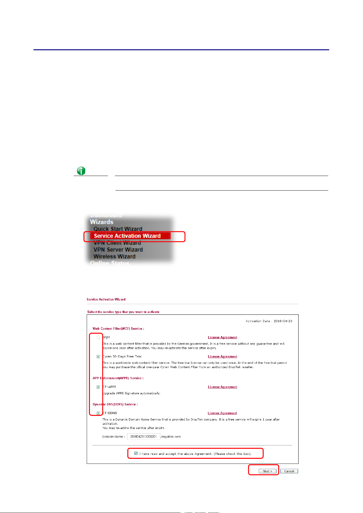
II--77 SSeerrvviiccee AAccttiivvaattiioonn WWiizzaarrdd
Service Activation Wizard can guide you to activate WCF service (Web Content Filter) with a
quick and easy way. For the Service Activation Wizard is only available for admin
operation, therefore, please type “admin/admin” on Username/Password while Logging
into the web user interface.
Service Activation Wizard is a tool which allows you to use trial version of WCF directly
without accessing into the server (MyVigor) located on http://myvigor.draytek.com. For
using Web Content Filter Profile, please
detailed information.
Now, follow the steps listed below to activate WCF feature for your router.
Info
1. Open Wizards>>Service Activation Wizard.
Such function is available only for Admin Mode.
refer to later section Web Content Filter Profile for
2. The screen of Service Activation Wizard will be shown as follows. You can activate the
Web content filter services and/or APPE enforcement service and / or DDNS service at
the same time or individually. When you finish the selection, please click Next.
56
Vigor2927 Series User’s Guide
 Loading...