

Draytek Vigor 2910, Vigor 2910i, Vigor 2910V, Vigor 2910G, Vigor 2910VG Quick Start Manual
...Page 1

i
Vigor 2910 Series Router
Quick Start Guide
Version: 1.0
Date: 2006/6/15
Page 2

i
Copyright Information
Copyright
Declarations
Copyright 2006 All rights reserved. This publication contains information that is
protected by copyright. No part may be reproduced, transmitted, transcribed,
stored in a retrieval system, or translated into any language without written
permission from the copyright holders.
Trademarks
The following trademarks are used in this document:
z Microsoft is a registered trademark of Microsoft Corp.
z Windows, Windows 95, 98, Me, NT, 2000, XP and Explorer are
trademarks of Microsoft Corp.
z Apple and Mac OS are registered trademarks of Apple Computer Inc.
z Other products may be trademarks or registered trademarks of their
respective manufacturers.
Safety Instructions and Approval
Safety
Instructions
z Read the installation guide thoroughly before you set up the router.
z The router is a complicated electronic unit that may be repaired only be
authorized and qualified personnel. Do not try to open or repair the router
yourself.
z Do not place the router in a damp or humid place, e.g. a bathroom.
z Do not stack the routers.
z The router should be used in a sheltered area, within a temperature range
of +5 to +40 Celsius.
z Do not expose the router to direct sunlight or other heat sources. The
housing and electronic components may be damaged by direct sunlight or
heat sources.
z Do not deploy the cable for LAN connection outdoor to prevent electronic
shock hazards.
z Keep the package out of reach of children.
z When you want to dispose of the router, please follow local regulations on
conservation of the environment.
Warranty
We warrant to the original end user (purchaser) that the router will be free from
any defects in workmanship or materials for a period of two (2) years from the
date of purchase from the dealer. Please keep your purchase receipt in a safe
place as it serves as proof of date of purchase. During the warranty period, and
upon proof of purchase, should the product have indications of failure due to
faulty workmanship and/or materials, we will, at our discretion, repair or replace
the defective products or components, without charge for either parts or labor, to
whatever extent we deem necessary tore-store the product to pro per o perating
condition. Any replacement will consist of a new or re-manufactured
functionally equivalent product of equal value, and will be offered solely at our
discretion. This warranty will not apply if the product is modified, misused,
tampered with, damaged by an act of God, or subjected to abnormal working
conditions. The warranty does not cover the bundled or licensed software of
other vendors. Defects which do not significantly affect the usability of the
product will not be covered by the warranty. We reserve the right to revise the
manual and online documentation and to make changes from time to time in the
contents hereof without obligation to notify any person of such revision or
changes.
Be a Registered
Owner
Web registration is preferred. You can register your Vigor router via
http://www.draytek.com. Alternatively, fill in the registration card and mail it to
the address found on the reverse side of the card.
Firmware & Tools
Updates
Due to the continuous evolution of DrayTek corporation, all routers will be
regularly upgraded. Please consult the DrayTek web site for more information on
newest firmware, tools and documents.
http://www.draytek.com
Page 3

ii
European Community Declarations
Manufacturer: DrayTek Corp.
Address: No. 26, Fu Shing Road, HuKou County, HsinChu Industrial Park, Hsin-Chu, Taiwan 303
Product: Vigor2910 Series Routers
DrayTek Corp. declares that Vigor2910 series of routers are in compliance with the following essential
requirements and other relevant provisions of R&TTE Directive 1999/5/EEC.
The product conforms to the requirements of Electro-Magnetic Compatibility (EMC) Directive
89/336/EEC by complying with the requirements set forth in EN55022/Class B and EN55024/Class B.
The product conforms to the requirements of Low Voltage (LVD) Directive 73/23/EEC by complying with
the requirements set forth in EN60950.
The Vigor2910 Series are designed for the WLAN 2.4GHz network throughput EC re gi o n , Swi t zerl an d,
and the restrictions of France.
Regulatory Information
Federal Communication Commission Interference Statement
This equipment has been tested and found to comply with the limits for a Class B digital device, pursuant
to Part 15 of the FCC Rules. These limits are designed to provide reasonable protection against harmful
interference in a residential installation. This equipment generates, uses and can radiate radio frequency
energy and, if not installed and used in accordance with the instructions, may cause harmful interference to
radio communications. However, there is no guarantee that interference will not occur in a particular
installation. If this equipment does cause harmful interference to radio or television reception, which can
be determined by turning the equipment off and on, the use is encouraged to try to correct the interference
by one of the following measures:
z Reorient or relocate the receiving antenna.
z Increase the separation between the equipment and receiver.
z Connect the equipment into an outlet on a circuit different form that to which the receiver is
connected.
z Consult the dealer or an experienced radio/TV technician for help.
This device complies with Part 15 of the FCC Rules. Operation is subject to the following two conditions:
(1) This device may not cause harmful interference, and
(2) This device may accept any interference received, including interference that may cause undesired
operation.
Taiwanese BSMI (Bureau of Standards, Metrology and Inspection) A Warning:
Warning: This device might cause interference of radio frequency under the environment of dwelling. In
such condition, the users might be asked to adopt some proper strategies.
Please visit www.draytek.com/contact_us/WEEE.php.
Page 4

iii
TTaabbllee ooff CCoonntteennttss
1. Introduction........................................................................................................... 1
1.1 LED Indicators and Connectors.................................................................................................2
1.1.1 For Vigor2910 ............................................................................................................... 2
1.1.2 For Vigor2910G............................................................................................................. 3
1.1.3 For Vigor2910i............................................................................................................... 4
1.1.4 For Vigor2910V............................................................................................................. 5
1.1.5 For Vigor2910VG..........................................................................................................6
1.1.6 For Vigor2910VGi ......................................................................................................... 7
1.2 Package Content........................................................................................................................ 8
2. Installing Your Vigor Router................................................................................. 9
2.1 Hardware Installation..................................................................................................................9
3. Configuring Web Pages......................................................................................11
3.1 Basic Configuration...................................................................................................................11
3.2 Wireless LAN Settings .............................................................................................................15
3.2.1 Basic Wireless LAN Concept......................................................................................15
3.2.2 General Settings ......................................................................................................... 16
3.2.3 Security Settings.........................................................................................................17
4. Trouble Shooting................................................................................................ 19
4.1 Checking If the Hardware Status Is OK or Not.........................................................................19
4.2 Checking If the Network Connection Settings on Your Computer Is OK or Not ...................... 19
4.3 Pinging the Router from Y our Computer.................................................................................. 22
4.4 Checking If the ISP Settings are OK or Not.............................................................................24
4.5 Backing to Factory Default Setting If Necessary...................................................................... 26
4.6 Contacting Your Dealer ............................................................................................................ 27
Page 5

1
11.. IInnttrroodduuccttiioonn
The Vigor2910 series router provides Dual-WAN interface (which is a confgiuration second
WAN) for
Internet access to make the Internet connection more reliable. The wireless
LAN supports more secure features and the transmission speed is up to 108Mbps
(SuperG
TM
). Object-oriented firewall is flexible and allows your network be safe. In
addition, throguh VoIP function, the communication fee for you and remote people can
be reduced.
CChhaarraacctteerriissttiiccss
¾ Easy Internet-sharing of your broadband connection
¾ Configurable 2
nd
WAN for policy-based load-balancing and fail-over
¾ Flexible traffic management lets your bandwidth more optimized
¾ Robust firewall to help protect your network from external attacks
¾ Comprehensive VPN facilities provide deployment of linked branch offices and
teleworkers
¾ Supper G
TM
provides up to 108Mpbs wireless bandwidth (G model)
¾ Voice over Internet capability (V model)
Page 6
2
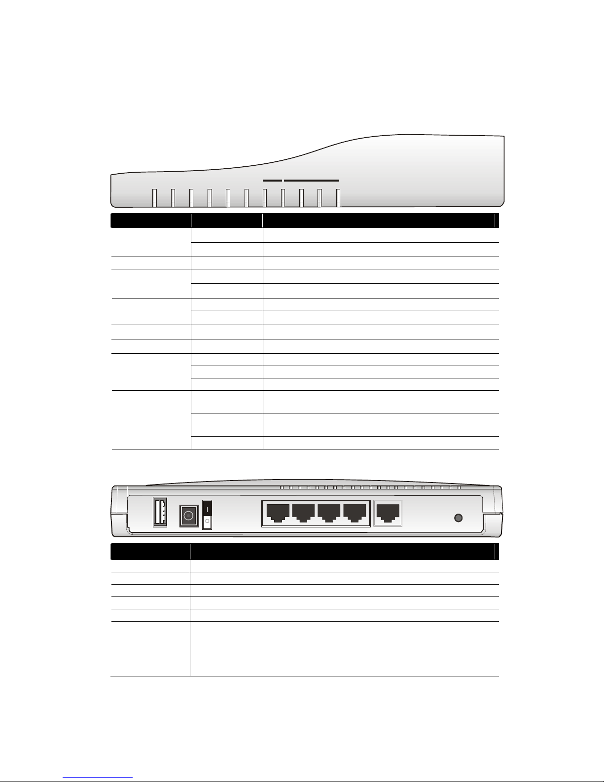
11..11 LLEEDD IInnddiiccaattoorrss aanndd CCoonnnneeccttoorrss
11..11..11 FFoorr VViiggoorr22991100
LLEEDD EExxppllaannaattiioonn
ACT
DMZ
QoS
Attack VPN
Printer
WAN
W2 P1
/
P2 P3 P4
LAN
W1
LED Status Explanation
Blinking
The router is powered on and running proper l y .
ACT (Activity)
Off
The router is powered off.
DMZ On DMZ Host is specified in certain site.
On The QoS function is active. QoS
Off The QoS function is inactive.
On DoS Defense function is active. Attack
Blinking An attack is detected.
VPN On The VPN tunnel is launched.
Printer On The USB interface printer is ready.
Orange A normal 10Mbps WAN link is ready.
Green A normal 100Mbps WAN link is ready.
WAN(W1-W2)
Blinking Ethernet packets are transmitting.
Orange A normal 10Mbps connection is through its corresponding
port.
Green A normal 100Mbps connection is through its
corresponding port.
LAN (P1, P2, P3,
P4)
Blinking Ethernet packets are transmitting.
CCoonnnneeccttoorr EExxppllaannaattiioonn
Factory
ResetW1
P1/W2
P2P3
P4
PWR
Printer
Interface Description
Printer Connecter for a USB printer.
PWR Connecter for a power adapter with 12-15VDC.
ON/OFF Power Switch.
LAN P4 – P1 Connecters for local networked devices.
W2/W1 Connecter for accessing Internet with the ADSL,ADSL2/2+ line
Factory Reset Restore the default settings.
Usage: Turn on the router (ACT LED is blinking). Press the hole and keep for
more than 5 seconds. When you see the ACT LED begins to blink rapidly than
usual, release the button. Then the router will restart with the factory default
configuration.
Page 7
3
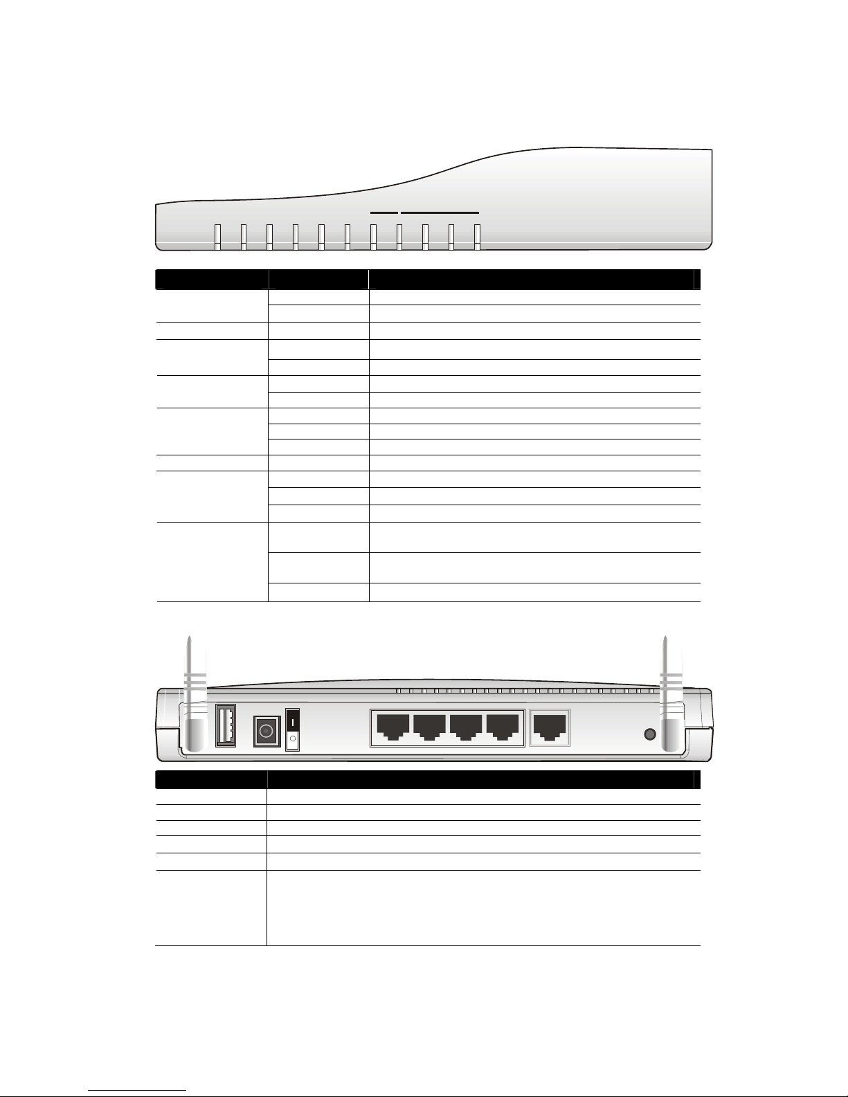
11..11..22 FFoorr VViiggoorr22991100GG
LLEEDD EExxppllaannaattiioonn
ACT
DMZ
QoS
Attack WLAN
Printer
WAN
W2 P1
/
P2 P3 P4
LAN
W1
LED Status Explanation
Blinking The router is powered on and running proper l y . ACT (Activity)
Off
The router is powered off.
DMZ On DMZ Host is specified in certain site.
On The QoS function is active. QoS
Off The QoS function is inactive.
On DoS Defense function is active. Attack
Blinking An attack is detected.
On Wireless access point is ready.
Blinking Wireless traffic goes through.
WLAN
Off Wireless access point is turned off.
Printer On The USB interface printer is ready.
Orange A normal 10Mbps WAN link is ready.
Green A normal 100Mbps WAN link is ready.
WAN(W1-W2)
Blinking Ethernet packets are transmitting.
Orange A normal 10Mbps connection is through its corresponding
port.
Green A normal 100Mbps connection is through its corresponding
port.
LAN (P1, P2, P3,
P4)
Blinking Ethernet packets are transmitting.
CCoonnnneeccttoorr EExxppllaannaattiioonn
Factory
Reset
PWR
Printer
W1
P1/W2
P2P3
P4
Interface Description
Printer Connecter for a USB printer.
PWR Connecter for a power adapter with 12-15VDC.
ON/OFF Power Switch.
LAN P4 – P1 Connecters for local networked devices.
W2/W1 Connecter for accessing Internet with the ADSL,ADSL2/2+ line
Factory Reset Restore the default settings.
Usage: Turn on the router (ACT LED is blinking). Press the hole and keep for
more than 5 seconds. When you see the ACT LED begins to blink rapidly than
usual, release the button. Then the router will restart with the factory default
configuration.
Page 8
4
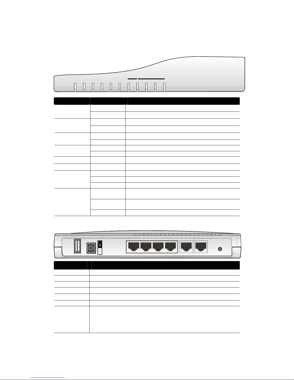
11..11..33 FFoorr VViiggoorr22991100ii
LLEEDD EExxppllaannaattiioonn
ACT
ISDN
QoS
Attack VPN
Printer
WAN
W2 P1
/
P2 P3 P4
LAN
W1
LED Status Explanation
Blinking
The router is powered on and running proper l y .
ACT (Activity)
Off
The router is powered off.
On
The ISDN network is correctly setup.
ISDN
Blinking
A successful connection on the ISDN BRI B1/B2 channel.
On The QoS function is active. QoS
Off The QoS function is inactive.
On DoS Defense function is active. Attack
Blinking An attack is detected.
VPN On The VPN tunnel is launched.
Printer On The USB interface printer is ready.
Orange A normal 10Mbps WAN link is ready.
Green A normal 100Mbps WAN link is ready.
WAN(W1-W2)
Blinking Ethernet packets are transmitting.
Orange A normal 10Mbps connection is through its corresponding
port.
Green A normal 100Mbps connection is through its corresponding
port.
LAN (P1, P2,
P3, P4)
Blinking Ethernet packets are transmitting.
CCoonnnneeccttoorr EExxppllaannaattiioonn
Factory
Reset
PWR
Printer
ISDN
W1
P1/W2
P2P3P4
Interface Description
Printer Connecter for a USB printer.
PWR Connecter for a power adapter with 12-15VDC.
ON/OFF Power Switch.
LAN P4 – P1 Connecters for local networked devices.
W2/W1 Connecter for accessing Internet with the ADSL,ADSL2/2+ line
ISDN Connecter for NT1 (or NT1+) box provided by ISD N service provider.
Factory Reset Restore the default settings.
Usage: Turn on the router (ACT LED is blinking). Press the hole and keep for
more than 5 seconds. When you see the ACT LED begins to blink rapidly than
usual, release the button. Then the router will restart with the factory default
configuration.
Page 9
5
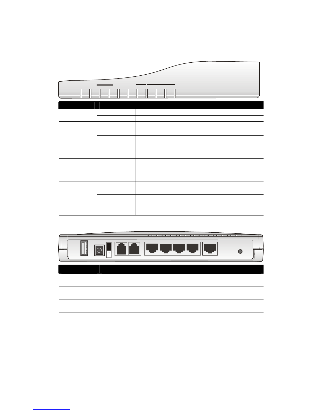
11..11..44 FFoorr VViiggoorr22991100VV
LLEEDD EExxppllaannaattiioonn
A
CT DMZ
VPN Printer P2 P3 P4
LAN
FXS1
FXS2
Phone
WAN
W2 P1
/
W1
LED Status Explanation
Blinking
The router is powered on and running proper l y .
ACT (Activity)
Off The router is powered off.
DMZ On
DMZ Host is specified in certain site.
On The phone is off hook (the handset of phone is hanging). FXS1/FXS2
Blinking A phone call is incoming or on-line.
VPN On The VPN tunnel is launched.
Printer On The USB interface printer is ready.
Orange
A normal 10Mbps WAN link is ready.
Green
A normal 100Mbps WAN link is ready.
WAN(W1-W2)
Blinking
Ethernet packets are transmitting.
Orange
A normal 10Mbps connection is through its corresponding
port.
Green
A normal 100Mbps connection is through its corresponding
port.
LAN (P1, P2,
P3, P4)
Blinking
Ethernet packets are transmitting.
CCoonnnneeccttoorr EExxppllaannaattiioonn
Factory
Reset
W1P1/W2P2P3
P4
PWR
Printer
FXS2 FXS1
Interface Description
Printer Connecter for a USB printer.
PWR Connecter for a power adapter with 12-15VDC.
ON/OFF Power Switch.
FXS2 & FXS1 Connecters for telephone set and analog phone with VoIP communication.
LAN P4 – P1 Connecters for local networked devices.
W2/W1 Connecter for accessing Internet with the ADSL,ADSL2/2+ line
Factory Reset Restore the default settings.
Usage: Turn on the router (ACT LED is blinking). Press the hole and keep for
more than 5 seconds. When you see the ACT LED begins to blink rapidly than
usual, release the button. Then the router will restart with the factory default
configuration.
Page 10
6
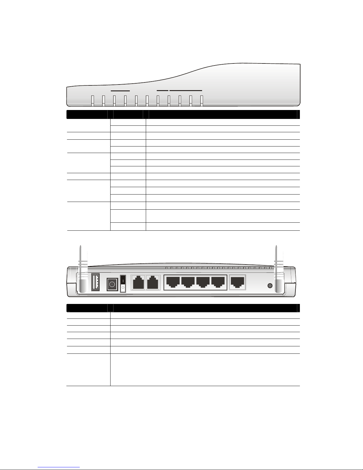
11..11..55 FFoorr VViiggoorr22991100VVGG
LLEEDD EExxppllaannaattiioonn
ACT DMZ
WLAN
Printer
P2 P3 P4
LAN
FXS1
FXS2
Phone
WAN
W2 P1
/
W1
LED Status Explanation
Blinking The router is powered on and running properly. ACT (Activity)
Off The router is powered off.
DMZ On
DMZ Host is specified in certain site.
On The phone is off hook (the handset of phone is hanging). FXS1/FXS2
Blinking A phone call is incoming or on-line.
On Wireless access point is ready.
Blinking Wireless traffic goes thro ugh.
WLAN
Off Wireless access point is turned off.
Printer On The USB interface printer is ready.
Orange A normal 10Mbps WAN link is ready.
Green A normal 100Mbps WAN link is ready.
WAN(W1-W2)
Blinking Ethernet packets are transmitting.
Orange A normal 10Mbps connection is through its corresponding port.
Green A normal 100Mbps connection is through its corresponding
port.
LAN (P1, P2,
P3, P4)
Blinking Ethernet packets are transmitting.
CCoonnnneeccttoorr EExxppllaannaattiioonn
Factory
Reset
PWR
Printer
W1
P1/W2P2P3
P4
FXS2 FXS1
Interface Description
Printer Connecter for a USB printer.
PWR Connecter for a power adapter with 12-15VDC.
ON/OFF Power Switch.
FXS2 & FXS1 Conn ecters for telephone set and the analog phone with VoIP communication.
LAN P4 – P1 Connecters for local networked devices.
W2/W1 Connecter for accessing Internet with the ADSL,ADSL2/2+ line
Factory Reset Restore the default settings.
Usage: Turn on the router (ACT LED is blinking). Press the hole and keep for
more than 5 seconds. When you see the ACT LED begins to blink rapidly than
usual, release the button. Then the router will restart with the factory default
configuration.
Page 11

7
11..11..66 FFoorr VViiggoorr22991100VVGGii
LLEEDD EExxppllaannaattiioonn
A
CT ISDN
WLAN
Printer
P2 P3 P4
LAN
FXS1
FXS2
Phone
WAN
W2 P1
/
W1
LED Status Explanation
Blinking The router is powered on and running properly. ACT (Activity)
Off The router is powered off.
On
The ISDN network is correctly setup.
ISDN
Blinking
A successful connection on the ISDN BRI B1/B2 channel.
On The phone is off hook (the handset of phone is hanging). FXS1/FXS2
Blinking A phone call is incoming or on-line.
On Wireless access point is ready.
Blinking Wireless traffic goes thro ugh.
WLAN
Off Wireless access point is turned off.
Printer On The USB interface printer is ready.
Orange A normal 10Mbps WAN link is ready.
Green A normal 100Mbps WAN link is ready.
WAN(W1-W2)
Blinking Ethernet packets are transmitting.
Orange A normal 10Mbps connection is through its corresponding port.
Green A normal 100Mbps connection is through its corresponding
port.
LAN (P1, P2,
P3, P4)
Blinking Ethernet packets are transmitting.
CCoonnnneeccttoorr EExxppllaannaattiioonn
Factory
Reset
PWR
Printer
W1
P1/W2P2P3
P4
FXS2 FXS1
ISDN
Interface Description
Printer
Connecter for a USB printer.
PWR
Connecter for a power adapter with 12-15VDC.
ON/OFF
Power Switch.
FXS2 & FXS1
Connecters for telephone set and analog phone with VoIP communication.
LAN P4 – P1 Connecters for local networked devices.
W2/W1 Connecter for accessing Internet with the ADSL,ADSL2/2+ line
ISDN Connecter for NT1 (or NT1+) box provided by ISD N service provider.
Factory Reset Restore the default settings.
Usage: Turn on the router (ACT LED is blinking). Press the hole and keep for
more than 5 seconds. When you see the ACT LED begins to blink rapidly than
usual, release the button. Then the router will restart with the factory default
configuration.
Page 12
8
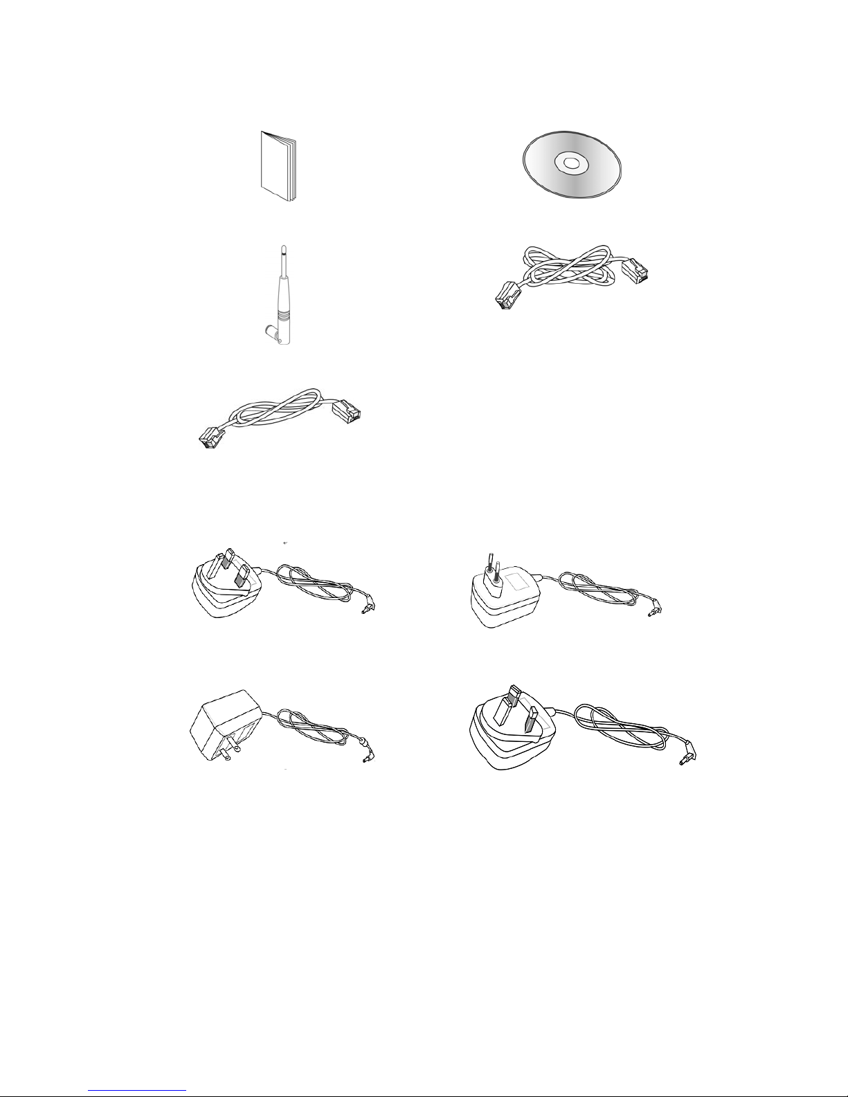
11..22 PPaacckkaaggee CCoonntteenntt
nQuick Start Guide
oCD
p
Antenna for G models
qRJ-45 Cable (Ethernet)
r
RJ-45 to RJ-45 Cable for i models
s
The type of the power adapter depends on the country that the router will be installed:
UK-type power adapter
EU-type power adapter
USA/Taiwan-type power adapter
AU/NZ-type power adapter
Page 13
9
22.. IInnssttaalllliinngg YYoouurr VViiggoorr RRoouutteerr
This section will guide you to install the router through hardware connection and
configure the router’s settings through web browser.
22..11 HHaarrddwwaarree IInnssttaallllaattiioonn
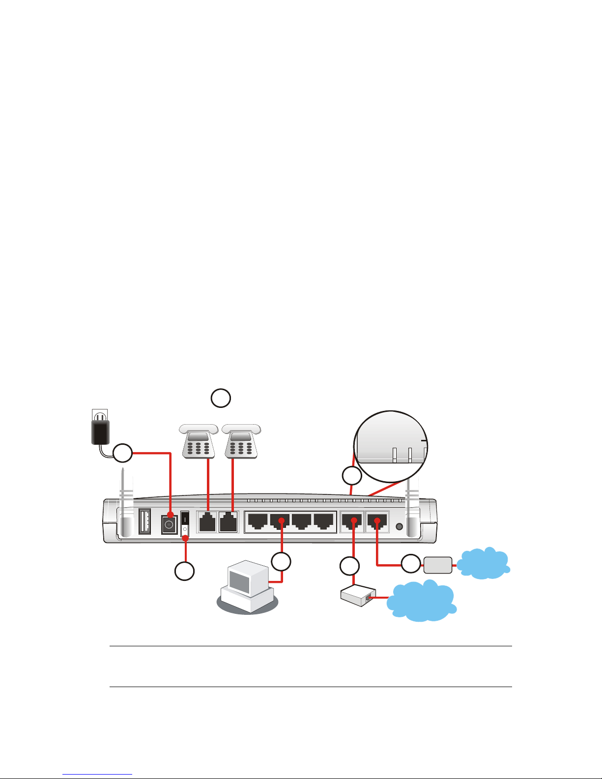
Before starting to configure the router, you have to connect your devices correctly.
1. Connect this device to a router/modem with an Ethernet cable.
2. Connect one port of 4-port switch to your computer with a RJ-45 cable. This device
allows you to connect 4 PCs directly.
3. Connect one end of the power cord to the power port of this device. Connect the
other end to the wall outlet of electricity.
4. Connect the telephone sets with phone lines (for using VoIP function). For the user
of the model without VoIP ports, skip this step.
5. Connect the ISDN NT1/1+ box with ISDN cable. This connection is available for
Europe only.
6. Power on the router.
7. Check the ACT LED to assure network connections.
(For the detailed information of LED status, please refer to section 1.1.)
Factory
Reset
PWR
Printer
W1
P1/W2P2P3
P4
FXS2 FXS1
ISDN
A
CT
WLAN
ADSL2+
Link
Data
Internet
2
4
3
A
CT
QoS
FX
Analog Phone Ana log Phone
Phone
Line
6
7
Cable/DSL
Modem
1
5
NT1/1+
ISDN
Caution: Each of the FXS ports can be connected to an analog phone only. Do not
connect the FXS ports to the telephone wall jack. This connection might damage your
router.
Page 14

10
This page is left blank.
Page 15
11
33.. CCoonnffiigguurriinngg WWeebb PPaaggeess
33..11 BBaassiicc CCoonnffiigguurraattiioonn
The Quick Start Wizard is designed for you to easily set up your router for Internet
access. You can directly access the Quick Start Wizard via Web Configurator.
1. Make sure your PC connects to the router correctly.
Notice: You may either simply set up your computer to get IP dynamically
from the router or set up the IP address of the computer to be the same
subnet as the default IP address of Vigor router 192.168.1.1. For the
detailed information, please refer to the later section - Trouble Shooting of
the guide.
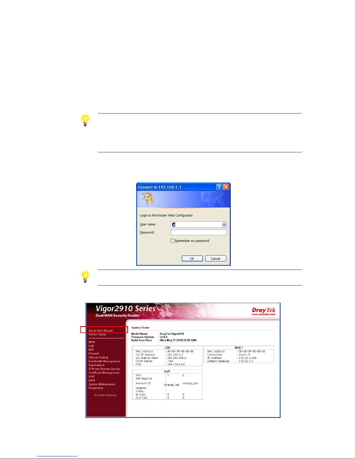
2. Open a web browser on your PC and type http://192.168.1.1. A pop-up window will
open to ask for username and password. Do not type any word on the window and
click OK for next screen.
Notice:
If you fail to access to the web configuration, please go to “Trouble
Shooting” for detecting and solving your problem.
3. Now, the Main Screen will pop up. Click Quick Start Wizard.
Page 16
12
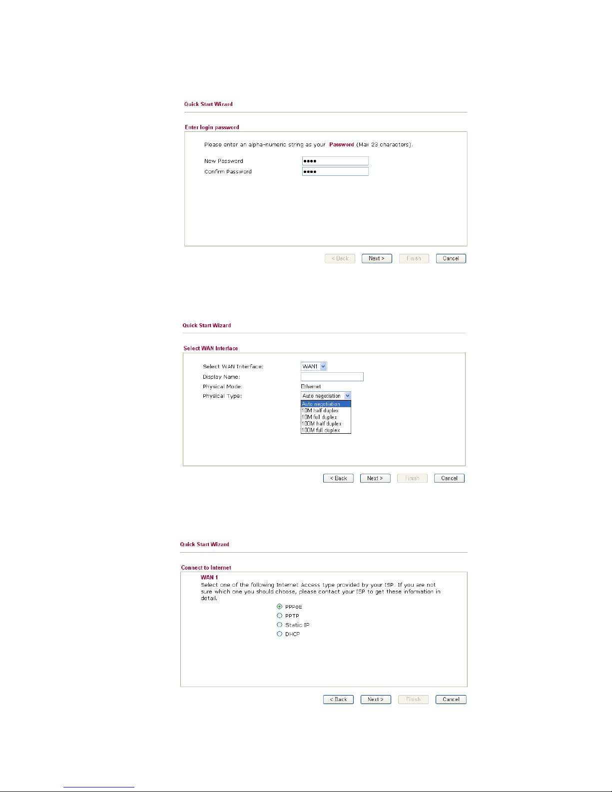
4. Enter the login password on the field of New Password and retype it on the field of
Retype New Password. Then click Next to continue.
5. On the next page as shown below, please select the WAN interface that you use.
Choose Auto negotiation as the physical type for your router. Then click Next for
next step.
6. On the next page as shown below, please select the appropriate Internet access type
according to the information from your ISP. For example, you should select PPPoE
mode if the ISP provides you PPPoE interface. Then click Next for next step.
Page 17
13
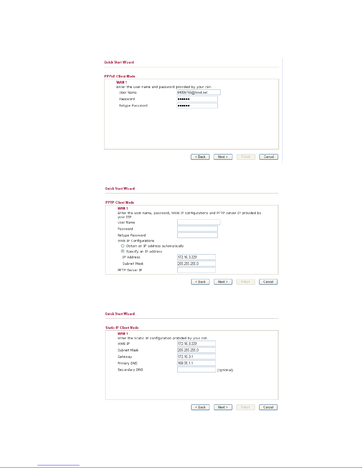
PPPoE: if you click PPPoE or PPPoA as the protocol, please manually enter the
Username/Password provided by your ISP. Then click Next.
PPTP: if you click PPTP, you will get the following page. Please type in all the
information originally provided by your ISP. Then click Next for next step.
Static IP: if you click Static IP, you will get the following page. Please type in the IP
address information originally provided by your ISP. Then click Next for next step.
Page 18
14
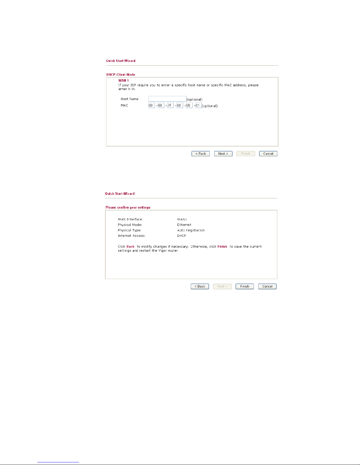
DHCP: if you click DHCP, you will get the following page. Simply click Next to
continue.
7. Now you can see the following screen. It indicates that the setup is complete.
Different types of connection modes will have different summary. Click Finish and
then restart the router. Afterward, you will enjoy surfing on the Internet.
Page 19
15
33..22 WWiirreelleessss LLAANN SSeettttiinnggss
For the user of Vigor2910/2910V/2910i, please skip this section.
For operating Vigor2910G/VG/VGi well, it is necessary for you to set the wireless LAN
settings for using wireless function. Please read the following section carefully for
configuring the settings for this router.
(The default value of Frequency Domain was set by factory depends on the reselling
region.)
33..22..11 BBaassiicc WWiirreelleessss LLAANN CCoonncceepptt
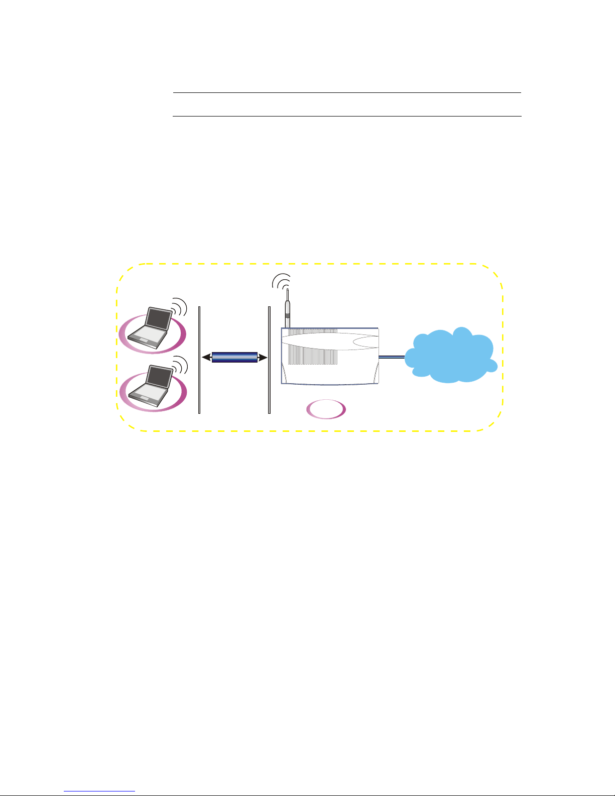
In an Infrastructure Mode of wireless network, Vigor wireless router plays a role as an
Access Point (AP) connecting to lots of wireless clients or Stations (STA). All the STAs
will share the same Internet connection with other wired hosts via Vigor wireless router.
WPA/WPA2
Internet
ADSL2+
AP
Client
Client
Page 20
16
33..22..22 GGeenneerraall SSeettttiinnggss
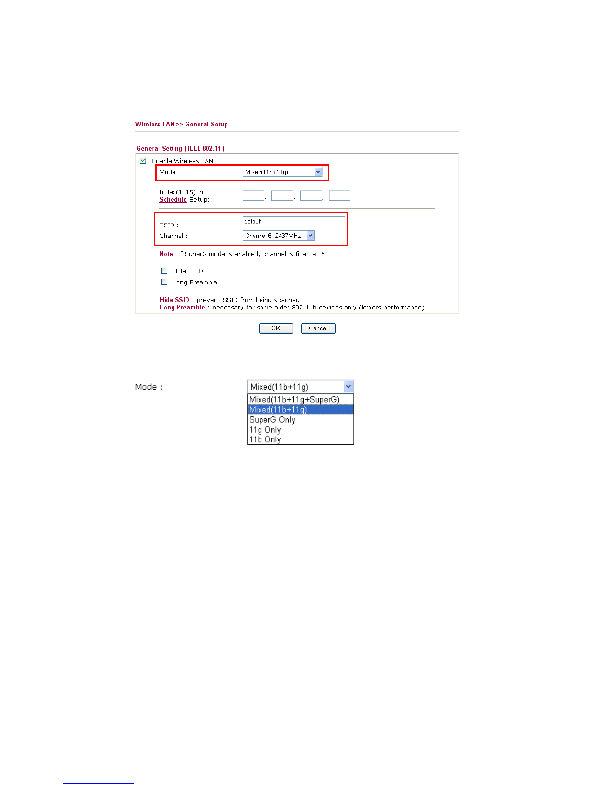
1. On the Wireless LAN group, select General Settings. The following page will be
shown.
2. Check the box Enable Wireless LAN to enable the wireless function.
3. Select an appropriate wireless mode.
Mixed
(11b+11g+SuperG)
The router can connect to IEEE802.11b, IEEE802.11g and
SuperG stations simultaneously. Please choose this mode if
your WAN clients have such features.
Mixed (11b+11g)
The router can connect to IEEE802.11b and IEEE802.11g
stations simultaneously. This is default settings. Choose this
mode if you have no idea to change the mode.
SuperG only
The router can connect to SuperG stations only.
11g-only
The router can connect to IEE802.11g stations only.
11b-only
The router can connect to IEE802.11b stations only.
4. Type in the name of the SSID and Channel. The default name for SSID is default.
We suggest you change it to a particular name for your necessity.
SSID (service set
identifier)
It is used to name the wireless LAN for this router, and it must
have the same content in client PC/notebook wireless card(s).
SSID can be any text numbers or various special characters.
Channel
It is a wireless channel for the router. The default channel is 6.
You can change it to an appropriate one if the selected
channel is under serious interference.
Page 21
17
33..22..33 SSeeccuurriittyy SSeettttiinnggss
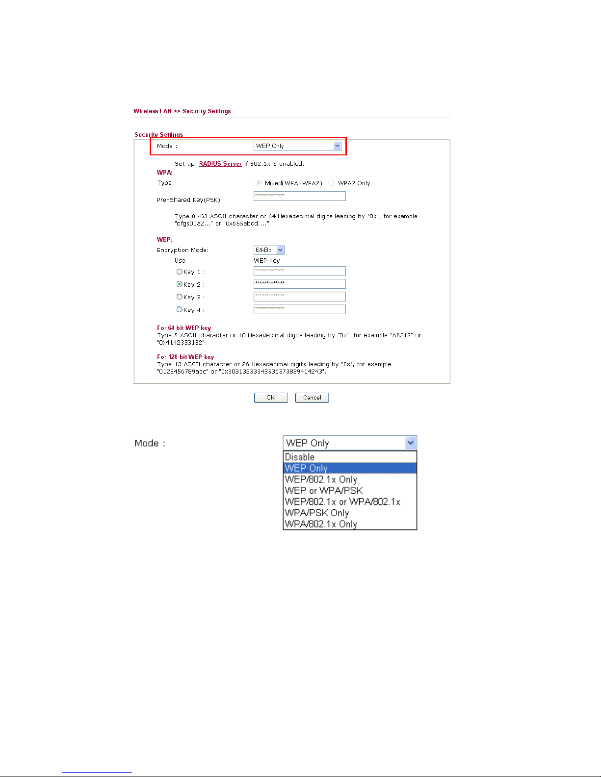
1. On the Wireless LAN group, select Security Settings.
2. Select an appropriate encryption mode to improve the security and privacy of your
wireless data packets.
Disable
Turn off the encryption mechanism. For the security of
your router, please select any one of the encryption mode
here.
WEP Only
Accepts only WEP clients and the encryption key should be
entered in WEP Key.
WEP/802.1x Only
Accept WEP clients with 802.1x authentication. Since the
key will be auto-negotiated during authentication, the field
of key setting below will be not available for input.
WEP or WPA/PSK
Accepts WEP and WPA clients with legal key accordingly.
Remember to select WPA type to define either Mixed or
WPA2 only in the field below.
Page 22

18
WEP/802.1x or
WPA/802.1x
Accept WEP or WPA clients with 802.1x authentication.
Remember to select WPA type to define either Mixed or
WPA2 only in the field below. Since the key will be
auto-negotiated during authentication, the field of key
setting below will be not available for input.
WPA/PSK Only
Accepts WPA clients and the encryption key should be
entered in PSK. Remember to select WPA type to define
either Mixed or WPA2 only in the field below.
WPA/802.1x Only
Accept WPA clients with 802.1x authentication. Remember
to select WPA type to define either Mixed or WPA2 only in
the field below. Since the key will be auto-negotiated
during authentication, the field of key setting below will be
not available for input.
3. For WPA encryption, type in 8~63 ASCII characters or 64 Hexadecimal digits
leading by 0x, for example "0123456789ABCD...." or "0x321253abcde....." on the
field of Pre-Shared Key (PSK). WPA encrypts each frame transmitted from the
radio using the Pre-Shared Key (PSK) which entered from this panel.
4. As to WEP encryption, select 64-bit or 128-bit as the encryption mode. For 64bits
WEP key, type in 5 ASCII characters or 10 hexadecimal digitals leading by 0x, for
example, ABCDE or 0x4142434445. And for 128bits WEP key, type in 13 ASCII
characters or 26 hexadecimal digits leading by 0x, for example, ABCDEFGHIJKLM
or 0x4142434445464748494A4B4C4D. Only one WEP key can be selected and
allows user to type in the characters.
5. Click OK to save settings.
Be aware that for the communication, all wireless devices must support the same
encryption bit length and share the same key. If WEP mode is selected, only one of four
preset keys can be selected at one time.
Page 23
19
44.. TTrroouubbllee SShhoooottiinngg
This section will guide you to solve abnormal situations if you cannot access into the
Internet after installing the router and finishing the web configuration. Please follow
sections below to check your basic installation status stage by stage.
¾ Checking if the hardware status is OK or not.
¾ Checking if the network connection settings on your computer are OK or not.
¾ Pinging the router from your computer.
¾ Checking if the ISP settings are OK or not.
¾ Backing to factory default setting if necessary.
If all above stages are done and the router still cannot run normally, it is the time for you
to contact your dealer for advanced help.
44..11 CChheecckkiinngg IIff tthhee HHaarrddwwaarree SSttaattuuss IIss OOKK oorr NNoott
Follow the steps below to verify the hardware status.
1. Check the power line and WLAN/LAN cable connections.
Refer to “2.1 Hardware Installation” for details.
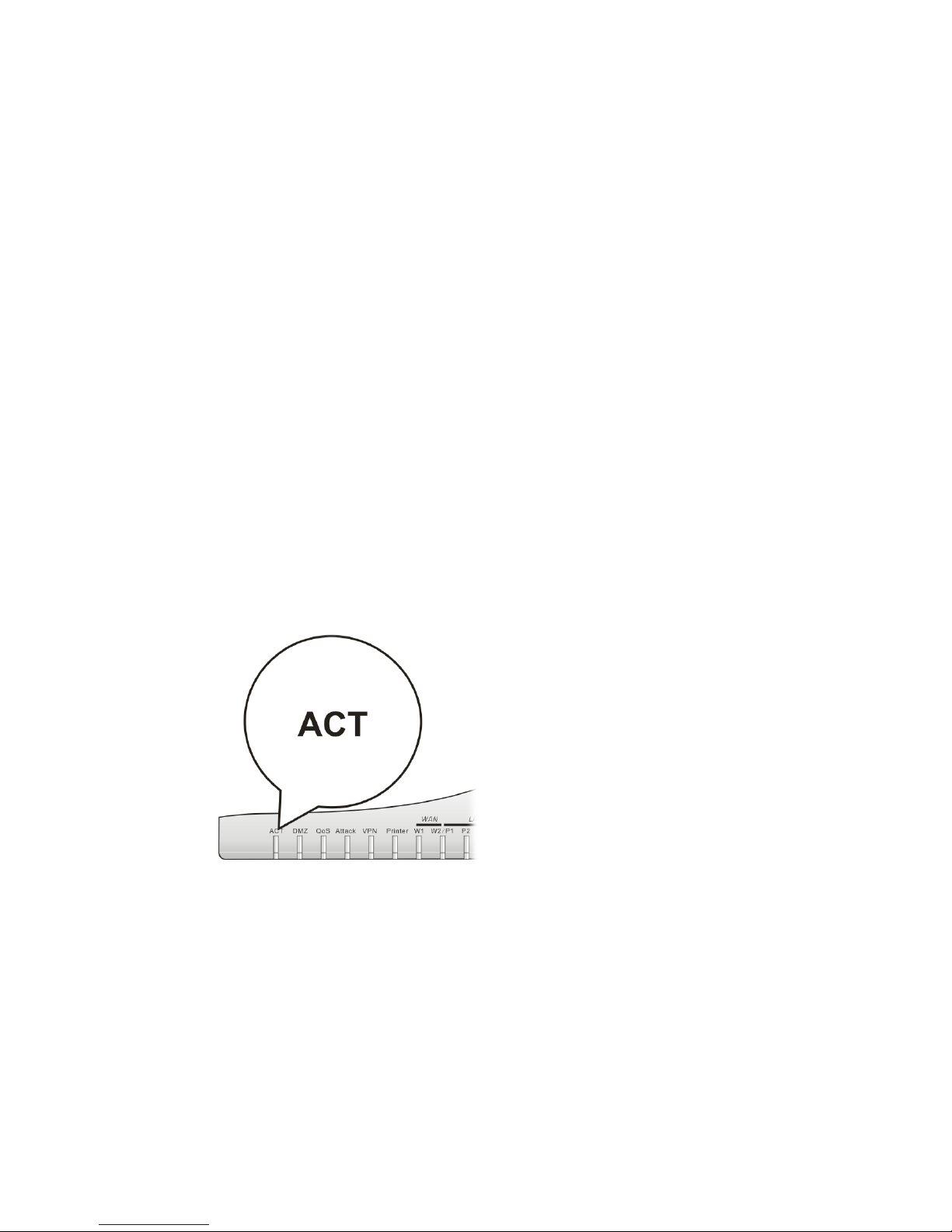
2. Turn on the router. Make sure the ACT LED blink once per second and the
correspondent LAN LED is bright.
3. If not, it means that there is something wrong with the hardware status. Simply back
to “2.1 Hardware Installation” to execute the hardware installation again. And
then, try again.
44..22 CChheecckkiinngg IIff tthhee NNeettwwoorrkk CCoonnnneeccttiioonn SSeettttiinnggss oonn
YYoouurr
CCoommppuutteerr IIss OOKK oorr NNoott
Sometimes the link failure occurs due to the wrong network connection settings. After
trying the above section, if the link is stilled failed, please do the steps listed below to
make sure the network connection settings is OK.
Page 24
20
FFoorr WWiinnddoowwss
The example is based on Windows XP. As to the examples for other
operation systems, please refer to the similar steps or find support notes in
www.draytek.com.
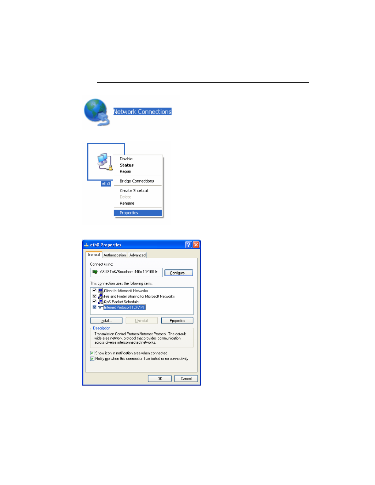
1. Go to Control Panel and then double-click on Network Connections.
2. Right-click on Local Area Connection and click on Properties.
3. Select Internet Protocol (TCP/IP) and then click Properties.
Page 25
21
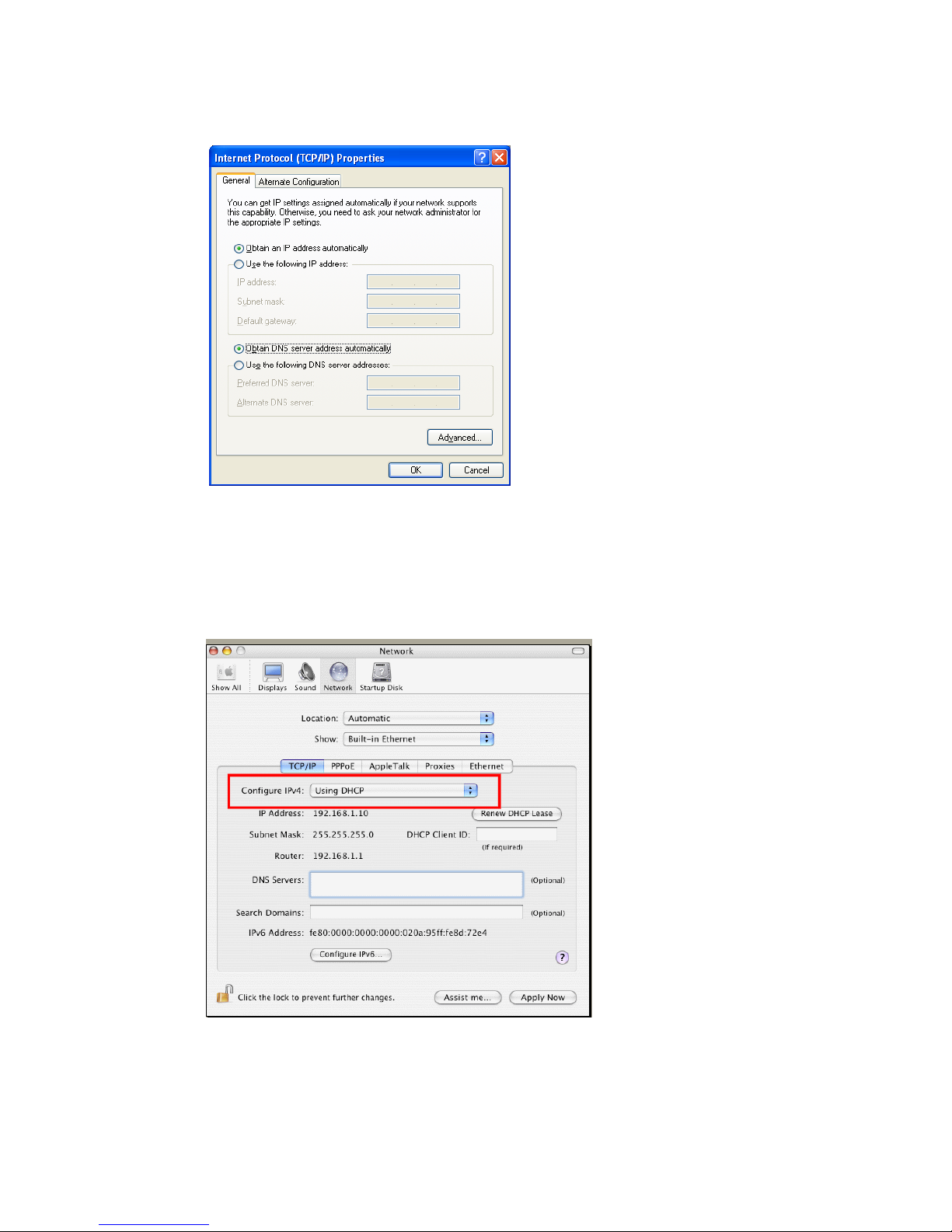
4. Select Obtain an IP address automatically and Obtain DNS server address
automatically.
FFoorr MMaaccOOss
1. Double click on the current used MacOs on the desktop.
2. Open the Application folder and get into Network.
3. On the Network screen, select Using DHCP from the drop down list of Configure
IPv4.
Page 26
22
44..33 PPiinnggiinngg tthhee RRoouutteerr ffrroomm YYoouurr CCoommppuutteerr
The default gateway IP address of the router is 192.168.1.1. For some reason, you might
need to use “ping” command to check the link status of the router. The most important
thing is that the computer will receive a reply from 192.168.1.1. If not, please check
the IP address of your computer. We suggest you setting the network connection as get IP
automatically. (Please refer to the section 4.2)
Please follow the steps below to ping the router correctly.
FFoorr WWiinnddoowwss
1. Open the Command Prompt window (from Start menu> Run).
2. Type command (for Windows 95/98/ME) or cmd (for Windows NT/ 2000/XP). The
DOS command dialog will appear.
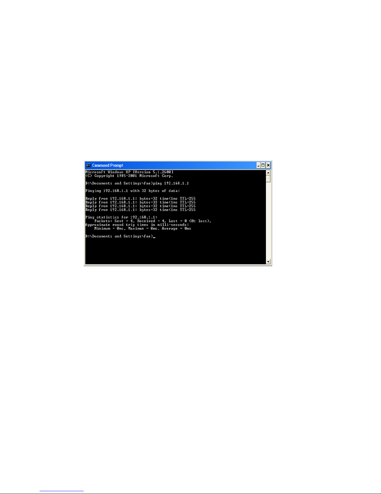
3. Type ping 192.168.1.1 and press [Enter]. It the link is OK, the line of “Reply from
192.168.1.1:bytes=32 time<1ms TTL=255” will appear.
4. If the line does not appear, please check the IP address setting of your computer.
FFoorr MMaaccOOss ((TTeerrmmiinnaall))
1. Double click on the current used MacOs on the desktop.
2. Open the Application folder and get into Utilities.
3. Double click Terminal. The Terminal window will appear.
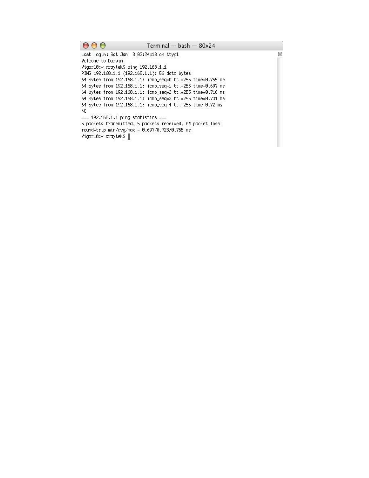
4. Type ping 192.168.1.1 and press [Enter]. It the link is OK, the line of “64 bytes
from 192.168.1.1: icmp_seq=0 ttl=255 time=xxxx ms” will appear.
Page 27
23
Page 28
24
44..44 CChheecckkiinngg IIff tthhee IISSPP SSeettttiinnggss aarree OOKK oorr NNoot
t
Open WAN >> Internet Access page and then check whether the ISP settings are set
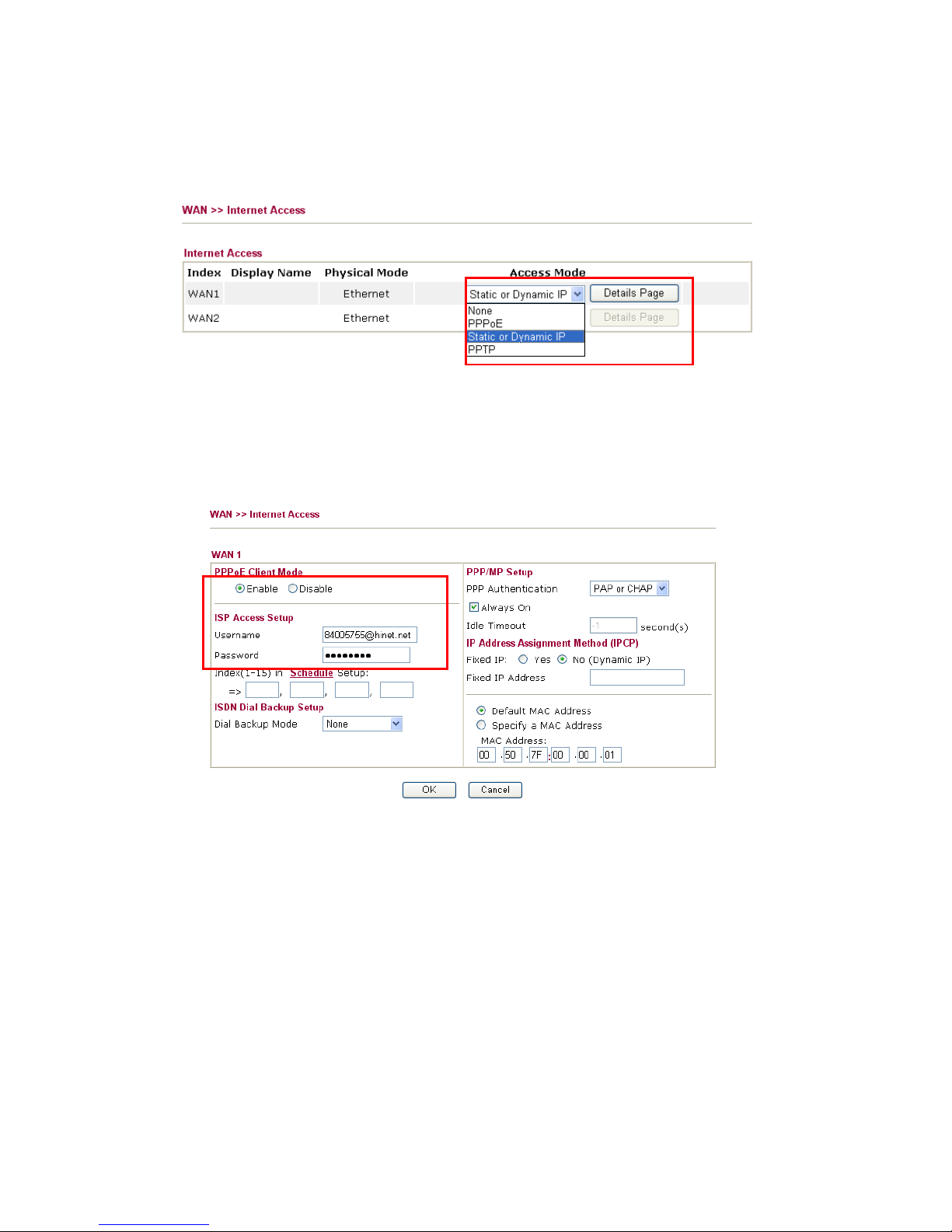
correctly. Click Details Page to review the settings that you configured previously.
FFoorr PPPPPPooEE UUsseerrss
1. Check if the Enable option is selected.
2. Check if Username and Password are entered with correct values that you got from
your ISP.
Page 29
25
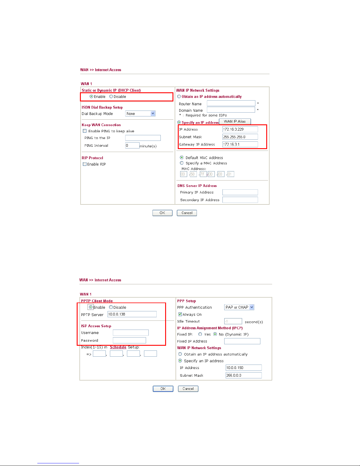
FFoorr SSttaattiicc UUsseerrss
1. Check if the Enable option for Broadband Access is selected.
2. Check if WAN IP Network Settings is set appropriately.
3. Check if IP Address, Subnet Mask and Gateway are set correctly (must identify
with the values from your ISP) if you choose Specify an IP address.
FFoorr PPPPTTPP UUsseerrss
1. Check if the Enable option for PPTP Link is selected.
2. Check if PPTP Server, Username, and Password are set correctly (must identify
with the values from your ISP).
Page 30
26
3. Check if WAN IP Network Settings are set properly. If you select Specify an IP
address, you have to type in the values of IP Address and Subnet Mask manually.
Be sure the values that you type identify with the values from your ISP.
44..55 BBaacckkiinngg ttoo FFaaccttoorryy DDeeffaauulltt SSeettttiinngg IIff NNeecceessssaarry
y
Sometimes, a wrong connection can be improved by returning to the default settings. Try
to reset the router by software or hardware.
Warning: After pressing factory default setting, you will loose all settings
you did before. Make sure you have recorded all useful settings before you
pressing. The password of factory default is null.
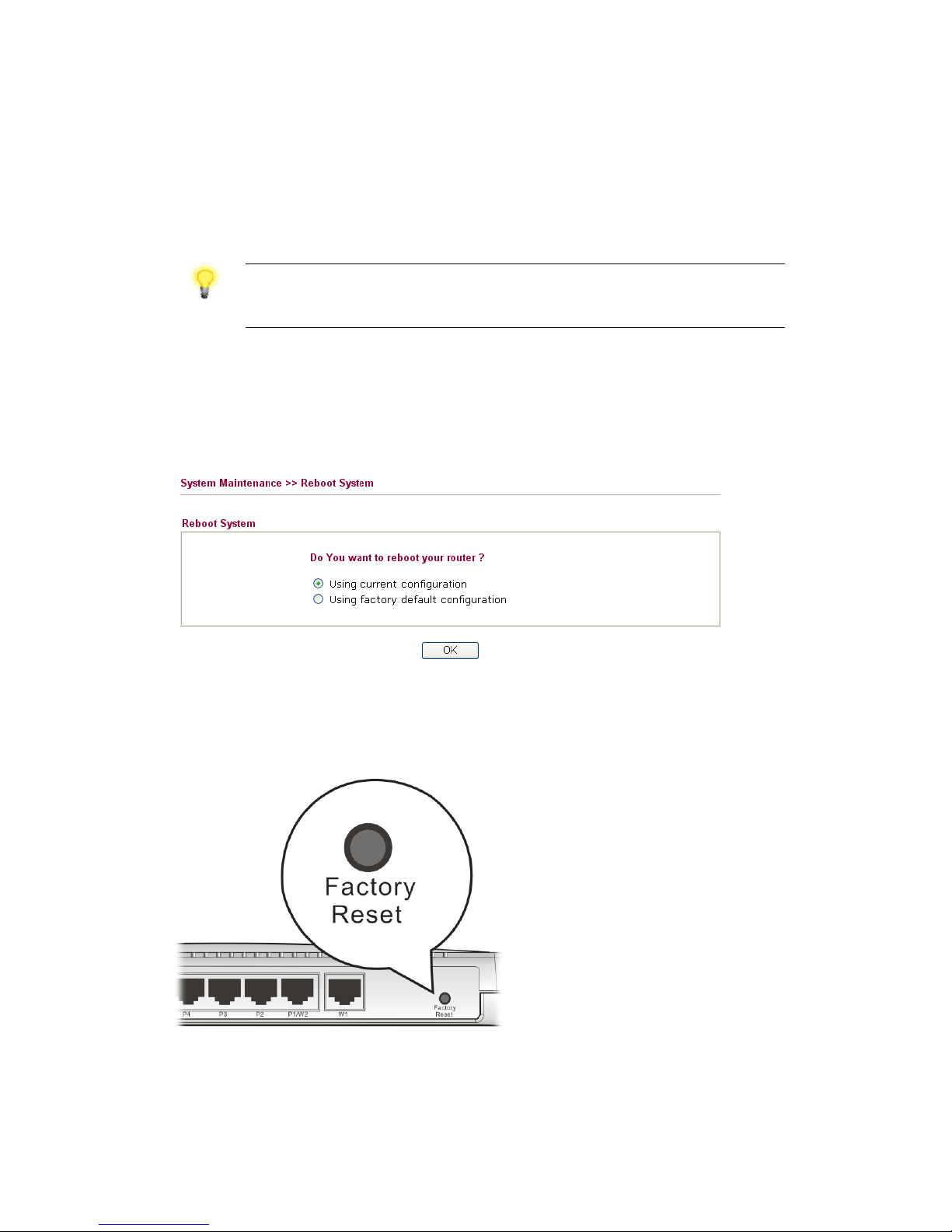
SSooffttwwaarree RReesseett
You can reset the router to factory default via Web page.
Go to System Maintenance and choose Reboot System on the web page. The following
screen will appear. Choose Using factory default configuration and click OK. After few
seconds, the router will return all the settings to the factory settings.
HHaarrddwwaarree RReesseett
While the router is running (ACT LED blinking), press the Factory Reset button and
hold for more than 5 seconds. When you see the ACT LED blinks rapidly, please release
the button. Then, the router will restart with the default configuration.
After restore the factory default setting, you can configure the settings for the router again
to fit your personal request.
Page 31

27
44..66 CCoonnttaaccttiinngg YYoouurr DDeeaalleerr
If the router still cannot work correctly after trying many efforts, please contact your
dealer for further help right away. For any questions, please feel free to send e-mail to
[email protected].
 Loading...