

Page 1
Page 2

Vigor2865 Series
35b Security Firewall
User’s Guide
Version: 1.1_(01)
Firmware Version: V4.2.0.1
(For future update, please visit DrayTek web site)
Date: December 10, 2020
ii
Vigor2865 Series User’s Guide
Page 3

Copyrights
© All rights reserved. This publication contains information that is protected by copyright. No part may be
reproduced, transmitted, transcribed, stored in a retrieval system, or translated into any language without
written permission from the copyright holders.
Trademarks
The following trademarks are used in this document:
Microsoft is a registered trademark of Microsoft Corp.
Windows 7, 8, 10 and Explorer are trademarks of Microsoft Corp.
Apple and Mac OS are registered trademarks of Apple Inc.
Other products may be trademarks or registered trademarks of their respective manufacturers.
Safety Instructions
Read the installation guide thoroughly before you set up the router.
The router is a complicated electronic unit that may be repaired only be authorized and qualified personnel.
Do not try to open or repair the router yourself.
Do not place the router in a damp or humid place, e.g. a bathroom.
The router should be used in a sheltered area, within a temperature range of +5 to +40 Celsius.
Do not expose the router to direct sunlight or other heat sources. The housing and electronic components
may be damaged by direct sunlight or heat sources.
Do not deploy the cable for LAN connection outdoor to prevent electronic shock hazards.
Keep the package out of reach of children.
When you want to dispose of the router, please follow local regulations on conservation of the environment.
Warranty
We warrant to the original end user (purchaser) that the router will be free from any defects in workmanship
or materials for a period of two (2) years from the date of purchase from the dealer. Please keep your
purchase receipt in a safe place as it serves as proof of date of purchase. During the warranty period, and upon
proof of purchase, should the product have indications of failure due to faulty workmanship and/or materials,
we will, at our discretion, repair or replace the defective products or components, without charge for either
parts or labor, to whatever extent we deem necessary tore-store the product to proper operating condition.
Any replacement will consist of a new or re-manufactured functionally equivalent product of equal value, and
will be offered solely at our discretion. This warranty will not apply if the product is modified, misused,
tampered with, damaged by an act of God, or subjected to abnormal working conditions. The warranty does
not cover the bundled or licensed software of other vendors. Defects which do not significantly affect the
usability of the product will not be covered by the warranty. We reserve the right to revise the manual and
online documentation and to make changes from time to time in the contents hereof without obligation to
notify any person of such revision or changes.
Be a Registered Owner
Web registration is preferred. You can register your Vigor router via http://www.DrayTek.com.
Firmware & Tools Updates
Due to the continuous evolution of DrayTek technology, all routers will be regularly upgraded. Please consult
the DrayTek web site for more information on newest firmware, tools and documents.
http://www.DrayTek.com
Vigor2865 Series User’s Guide
iii
Page 4

v
TTaabbllee ooff CCoonntteennttss
Part I Installation.......................................................................................i
I-1 Introduction .................................................................................................. 1
I-1-1 Indicators and Connectors .......................................................................... 2
I-1-1-1 Vigor2865 ................................................................................... 2
I-1-1-2 Vigor2865L.................................................................................. 4
I-1-1-3 Vigor2865ac / Vigor2865Lac ............................................................... 6
I-1-2 Notes for Antenna Installation (for “L” model).................................................. 8
I-2 Hardware Installation......................................................................................10
I-2-1 Installing Vigor Router..............................................................................10
I-2-2 Wall-Mounted Installation..........................................................................11
I-2-3 Installing USB Printer to Vigor Router............................................................12
I-3 Accessing Web Page ........................................................................................19
I-4 Changing Password .........................................................................................21
I-5 Dashboard....................................................................................................23
I-5-1 Virtual Panel .........................................................................................24
I-5-2 Name with a Link....................................................................................25
I-5-3 Quick Access for Common Used Menu............................................................26
I-5-4 GUI Map...............................................................................................27
I-5-5 Web Console..........................................................................................29
I-5-6 Config Backup........................................................................................30
I-5-7 Logout.................................................................................................30
I-5-8 Online Status.........................................................................................31
I-5-8-1 Physical Connection......................................................................31
I-5-8-2 Virtual WAN ...............................................................................33
I-6 Quick Start Wizard..........................................................................................35
I-6-1 ADSL/VDSL2 Connection on WAN1................................................................36
I-6-2 Ethernet Connection on WAN2 ....................................................................42
I-6-3 Wireless 2.4G/5G Connection on WAN3/WAN4.................................................51
I-6-4 USB Connection on WAN5/WAN6..................................................................57
I-7 Service Activation Wizard .................................................................................59
I-8 Registering Vigor Router...................................................................................61
Part II Connectivity................................................................................. 63
II-1 WAN ..........................................................................................................64
Web User Interface........................................................................................66
II-1-1 General Setup.......................................................................................66
II-1-1-1 WAN1(ADSL/VDSL2)......................................................................69
II-1-1-2 WAN2 (Ethernet).........................................................................71
II-1-1-3 WAN3/WAN4 (Wireless 2.4G or 5G)...................................................73
II-1-1-4 WAN5 / WAN6 (USB).....................................................................75
II-1-2 Internet Access......................................................................................77
II-1-2-1 WAN1 Details Page (PPPoE / PPPoA, Physical Mode: VDSL2) .....................80
i
Vigor2865 Series User’s Guide
Page 5

II-1-2-2 WAN1 Details Page (MPoA/Static or Dynamic IP, Physical Mode: VDSL2).......83
II-1-2-3 WAN1 Details Page (PPPoE / PPPoA, Physical Mode: ADSL).......................87
II-1-2-4 WAN1 Details Page (MPoA/Static or Dynamic IP, Physical Mode: ADSL)........90
II-1-2-5 WAN2 Details Page (PPPoE, Physical Mode: Ethernet).............................95
II-1-2-6 WAN2 Details Page (Static or Dynamic IP, Physical Mode: Ethernet) ...........98
II-1-2-7 WAN2 Details Page (PPTP/L2TP, Physical Mode: Ethernet)..................... 102
II-1-2-8 WAN3~WAN4 Details Page (Static or Dynamic IP, Physical Mode: Wireless
2.4G/5G).......................................................................................... 104
II-1-2-9 WAN5~WAN6 Details Page ((PPP mode), Physical Mode: USB).................. 106
II-1-2-10 WAN5~WAN6 Details Page ((DHCP mode), Physical Mode: USB) .............. 109
II-1-2-11 WAN1~WAN6 Details Page for IPv6 – Offline..................................... 112
II-1-2-12 WAN1~WAN2 Details Page for IPv6 – PPP ......................................... 112
II-1-2-13 WAN1~WAN6 Details Page for IPv6 – TSPC........................................ 113
II-1-2-14 WAN1~WAN6 Details Page for IPv6 – AICCU ...................................... 115
II-1-2-15 WAN1~WAN2 Details Page for IPv6 – DHCPv6 Client............................ 116
II-1-2-16 WAN1~WAN2 Details Page for IPv6 – Static IPv6................................. 118
II-1-2-17 WAN1~WAN2 Details Page for IPv6 – 6in4 Static Tunnel ....................... 120
II-1-2-18 WAN1~WAN2 Details Page for IPv6 – 6rd in ...................................... 122
II-1-3 Multi-PVC/VLAN................................................................................... 124
II-1-4 WAN Budget ....................................................................................... 132
II-1-4-1 General Setup .......................................................................... 132
II-1-4-2 Status .................................................................................... 135
Application Notes........................................................................................ 136
A-1 How to set up Multi-PVC for triple play deployment?................................ 136
A-2 How to configure IPv6 on WAN interface?.............................................. 141
II-2 LAN......................................................................................................... 146
Web User Interface...................................................................................... 148
II-2-1 General Setup..................................................................................... 148
II-2-1-1 Details Page for LAN1 – Ethernet TCP/IP and DHCP Setup...................... 150
II-2-1-2 Details Page for LAN2 ~ LAN8 and DMZ ............................................ 153
II-2-1-3 Details Page for IP Routed Subnet .................................................. 155
II-2-1-4 Details Page for LAN IPv6 Setup..................................................... 157
II-2-1-5 DHCP Server Options .................................................................. 160
II-2-2 VLAN................................................................................................ 163
II-2-3 Bind IP to MAC..................................................................................... 167
II-2-4 LAN Port Mirror.................................................................................... 169
II-2-5 Wired 802.1x ...................................................................................... 170
II-3 NAT......................................................................................................... 171
Web User Interface...................................................................................... 172
II-3-1 Port Redirection .................................................................................. 172
II-3-2 DMZ Host........................................................................................... 176
II-3-3 Open Ports......................................................................................... 179
II-3-4 Port Triggering.................................................................................... 181
II-3-5 ALG.................................................................................................. 184
II-4 Applications............................................................................................... 185
Web User Interface...................................................................................... 187
II-4-1 Dynamic DNS....................................................................................... 187
II-4-2 LAN DNS / DNS Forwarding...................................................................... 193
II-4-3 DNS Security....................................................................................... 197
Vigor2865 Series User’s Guide
v
Page 6

II-4-3-1 General Setup .......................................................................... 197
II-4-3-2 Domain Diagnose....................................................................... 198
II-4-4 Schedule ........................................................................................... 199
II-4-5 RADIUS/TACACS+ ................................................................................. 202
II-4-5-1 External RADIUS........................................................................ 202
II-4-5-2 Internal RADIUS ........................................................................ 203
II-4-5-3 External TACACS+...................................................................... 206
II-4-6 Active Directory/LDAP........................................................................... 207
II-4-6-1 General Setup .......................................................................... 207
II-4-6-2 Active Directory / LDAP Profiles .................................................... 208
II-4-7 UPnP ................................................................................................ 210
II-4-8 IGMP ................................................................................................ 211
II-4-8-1 General Setting ........................................................................ 211
II-4-8-2 Working Group ......................................................................... 212
II-4-9 Wake on LAN ...................................................................................... 213
II-4-10 SMS / Mail Alert Service........................................................................ 214
II-4-10-1 SMS Alert............................................................................... 214
II-4-10-2 Mail Alert.............................................................................. 215
II-4-11 Bonjour ........................................................................................... 216
II-4-12 High Availability................................................................................. 219
II-4-12-1 General Setup......................................................................... 220
II-4-12-2 Config Sync ............................................................................ 222
II-4-13 Local 802.1X General Setup ................................................................... 224
Application Notes........................................................................................ 226
A-1 How to use High Availability?............................................................. 226
A-2 How to use DrayDDNS?..................................................................... 234
A-3 How to Implement the LDAP/AD Authentication for User Management? ......... 239
A-4 How to Configure Customized DDNS?.................................................... 242
II-5 Routing .................................................................................................... 246
Web User Interface...................................................................................... 247
II-5-1 Static Route ....................................................................................... 247
II-5-2 Load-Balance /Route Policy..................................................................... 253
II-5-3 BGP ................................................................................................. 263
II-5-3-1 Basic Settings........................................................................... 263
II-5-3-2 Static Network ......................................................................... 264
Application Notes........................................................................................ 265
A-1 How to set up Address Mapping with Route Policy? .................................. 265
A-2 How to use destination domain name in a route policy?............................. 267
A-3 Introduction to Load Balance/Route Policy ............................................ 269
II-6 LTE ......................................................................................................... 271
Web User Interface...................................................................................... 272
II-6-1 General Settings .................................................................................. 272
II-6-1-1 SMS Quota............................................................................... 272
II-6-1-2 SMS Inbox/Outbox ..................................................................... 273
II-6-2 SMS Inbox .......................................................................................... 274
II-6-3 Send SMS ........................................................................................... 277
II-6-4 Router Commands ................................................................................ 278
vi
Vigor2865 Series User’s Guide
Page 7

II-6-5 Status............................................................................................... 280
Part III Wireless LAN...............................................................................283
III-1 Wireless LAN (2.4GHz/5GHz).......................................................................... 284
Web User Interface...................................................................................... 287
III-1-1 Wireless Wizard .................................................................................. 287
III-1-2 General Setup .................................................................................... 291
III-1-3 Security............................................................................................ 293
III-1-4 Access Control.................................................................................... 295
III-1-5 WPS ................................................................................................ 297
III-1-6 WDS (for 5GHz)................................................................................... 300
III-1-7 Advanced Setting ................................................................................ 302
III-1-8 Station Control ................................................................................... 306
III-1-9 Bandwidth Management ........................................................................ 307
III-1-10 AP Discovery..................................................................................... 308
III-1-11 Airtime Fairness ................................................................................ 309
III-1-12 Band Steering (2.4 GHz)....................................................................... 311
III-1-13 Roaming.......................................................................................... 316
III-1-14 Station List ...................................................................................... 317
Part IV VPN..........................................................................................319
IV-1 VPN and Remote Access................................................................................ 320
Web User Interface...................................................................................... 321
IV-1-1 VPN Client Wizard ............................................................................... 321
IV-1-2 VPN Server Wizard............................................................................... 328
IV-1-3 Remote Access Control.......................................................................... 337
IV-1-4 PPP General Setup............................................................................... 338
IV-1-5 SSL General Setup ............................................................................... 340
IV-1-6 IPsec General Setup ............................................................................. 341
IV-1-7 IPsec Peer Identity............................................................................... 343
IV-1-8 VPN Matcher Setup .............................................................................. 345
IV-1-9 OpenVPN .......................................................................................... 347
IV-1-9-1 OpenVPN Server Setup ............................................................... 347
IV-1-9-2 Client Config........................................................................... 349
IV-1-10 Remote Dial-in User............................................................................ 351
IV-1-11 LAN to LAN ...................................................................................... 355
IV-1-12 VPN Trunk Management ....................................................................... 364
IV-1-13 Connection Management...................................................................... 369
Application Notes........................................................................................ 371
A-1 How to Build a LAN-to-LAN VPN Between Vigor Routers via IPsec Main Mode ... 371
A-2 How to Build a LAN-to-LAN VPN Between Vigor Routers via IKEv2................. 376
IV-2 Certificate Management ............................................................................... 379
Vigor2865 Series User’s Guide
vii
Page 8

Web User Interface...................................................................................... 380
IV-2-1 Local Certificate................................................................................. 380
IV-2-2 Trusted CA Certificate .......................................................................... 385
IV-2-3 Certificate Backup............................................................................... 388
IV-2-4 Self-Signed Certificate.......................................................................... 389
Part V Security .....................................................................................391
V-1 Firewall.................................................................................................... 392
Web User Interface...................................................................................... 394
V-1-1 General Setup..................................................................................... 394
V-1-2 Filter Setup........................................................................................ 399
V-1-3 Defense Setup..................................................................................... 409
V-1-3-1 DoS Defense............................................................................. 409
V-1-3-2 Spoofing Defense....................................................................... 412
V-1-4 Diagnose............................................................................................ 413
Application Notes........................................................................................ 416
A-1 How to Configure Certain Computers Accessing to Internet........................ 416
V-2 Central Security Management (CSM).................................................................. 419
Web User Interface...................................................................................... 420
V-2-1 APP Enforcement Profile ........................................................................ 420
V-2-2 APPE Signature Upgrade......................................................................... 422
V-2-3 URL Content Filter Profile....................................................................... 424
V-2-4 Web Content Filter Profile...................................................................... 428
V-2-5 DNS Filter Profile ................................................................................. 431
Application Notes........................................................................................ 433
A-1 How to Create an Account for MyVigor ................................................. 433
A-2 How to Block Facebook Service Accessed by the Use rs via W e b Cont ent Fil ter / UR L
Content Filter.................................................................................... 438
Part VI Management...............................................................................443
VI-1 System Maintenance.................................................................................... 444
Web User Interface...................................................................................... 445
VI-1-1 System Status..................................................................................... 445
VI-1-2 TR-069............................................................................................. 448
VI-1-3 Administrator Password......................................................................... 451
VI-1-4 User Password.................................................................................... 454
VI-1-5 Login Page Greeting............................................................................. 457
VI-1-6 Configuration Backup ........................................................................... 459
VI-1-7 Syslog/Mail Alert................................................................................. 462
VI-1-8 Time and Date.................................................................................... 465
VI-1-9 SNMP............................................................................................... 466
VI-1-10 Management..................................................................................... 468
VI-1-11 Panel Control.................................................................................... 473
viii
Vigor2865 Series User’s Guide
Page 9

VI-1-12 Self-Signed Certificate......................................................................... 477
VI-1-13 Reboot System.................................................................................. 479
VI-1-14 Firmware Upgrade.............................................................................. 480
VI-1-15 Firmware Backup............................................................................... 481
VI-1-16 Internal Service User List ..................................................................... 482
VI-1-17 Dashboard Control.............................................................................. 483
VI-2 Bandwidth Management................................................................................ 484
Web User Interface...................................................................................... 485
VI-2-1 Sessions Limit..................................................................................... 485
VI-2-2 Bandwidth Limit.................................................................................. 487
VI-2-3 Quality of Service................................................................................ 489
VI-2-4 APP QoS ........................................................................................... 495
VI-3 User Management....................................................................................... 496
Web User Interface...................................................................................... 497
VI-3-1 General Setup .................................................................................... 497
VI-3-2 User Profile ....................................................................................... 499
VI-3-3 User Group........................................................................................ 503
VI-3-4 User Online Status............................................................................... 504
Application Notes........................................................................................ 506
A-1 How to authenticate clients via User Management................................... 506
A-2 How to use Landing Page Feature ....................................................... 515
VI-4 Hotspot Web Portal ..................................................................................... 519
Web User Interface...................................................................................... 519
VI-4-1 Profile Setup...................................................................................... 519
VI-4-1-1 Login Method .......................................................................... 520
VI-4-1-2 Steps for Configuring a Web Portal Profile....................................... 520
VI-4-2 User Information................................................................................. 536
VI-4-2-1 User Info................................................................................ 536
VI-4-2-2 Database Setup........................................................................ 537
VI-4-3 Quota Management.............................................................................. 539
VI-4-4 PIN Generator .................................................................................... 542
VI-4-4-1 PIN Status .............................................................................. 542
VI-4-4-2 PIN Generator.......................................................................... 543
VI-4-4-3 PIN Voucher ............................................................................ 544
Application Notes........................................................................................ 546
A-1 How to create Facebook APP for Web Portal Authentication?...................... 546
A-2 How to create Google APP for Web Portal Authentication?......................... 552
VI-5 Central Management (VPN)............................................................................ 554
Web User Interface...................................................................................... 555
VI-5-1 General Setup .................................................................................... 555
VI-5-1-1 General Settings....................................................................... 555
VI-5-1-2 IPsec VPN Settings .................................................................... 556
VI-5-2 CPE Management................................................................................. 557
VI-5-2-1 Managed Device List.................................................................. 557
Vigor2865 Series User’s Guide
ix
Page 10

x
VI-5-2-2 CPE Maintenance...................................................................... 560
VI-5-2-3 Google Map............................................................................. 563
VI-5-3 VPN Management ................................................................................ 564
VI-5-4 Log & Alert........................................................................................ 565
Application Notes........................................................................................ 566
A-1 CVM Application - How to manage the CPE (router) through Vigor2865 series? . 566
A-2 CVM Application - How to build the VPN between remote devices and Vigor 2865
series? ............................................................................................. 569
A-3 CVM Application - How to upgrade CPE firmware through Vigor2865 series?.... 572
VI-6 Central Management (AP) ............................................................................. 575
Web User Interface...................................................................................... 576
VI-6-1 Dashboard......................................................................................... 576
VI-6-2 Status.............................................................................................. 577
VI-6-3 WLAN Profile...................................................................................... 578
VI-6-4 AP Maintenance .................................................................................. 583
VI-6-5 AP Map............................................................................................. 584
VI-6-6 Traffic Graph ..................................................................................... 589
VI-6-7 Temperature Sensor............................................................................. 590
VI-6-8 Rogue AP Detection ............................................................................. 590
VI-6-9 Event Log.......................................................................................... 593
VI-6-10 Total Traffic..................................................................................... 594
VI-6-11 Station Number................................................................................. 594
VI-6-12 Load Balance.................................................................................... 595
VI-7 Central Management (Switch)......................................................................... 597
Web User Interface...................................................................................... 598
VI-7-1 Status.............................................................................................. 598
VI-7-1-1 Switch Status .......................................................................... 598
VI-7-1-2 Switch Hierarchy...................................................................... 600
VI-7-1-3 Detailed Info........................................................................... 601
VI-7-1-4 TR069 Setting.......................................................................... 602
VI-7-2 Profile ............................................................................................. 603
VI-7-3 Group .............................................................................................. 606
VI-7-4 Maintenance...................................................................................... 608
VI-7-5 Alert and Log ..................................................................................... 609
VI-7-5-1 Alert Setup............................................................................. 609
VI-7-5-2 Switch and Port Setup................................................................ 610
VI-7-5-3 Alert Logs .............................................................................. 611
VI-7-6 Database Setup................................................................................... 612
VI-7-7 Support List....................................................................................... 613
VI-8 Central Management (External Devices) ............................................................ 614
Part VII Others......................................................................................615
VII-1 Objects Settings........................................................................................ 616
Web User Interface...................................................................................... 617
Vigor2865 Series User’s Guide
Page 11

xi
VII-1-1 IP Object ......................................................................................... 617
VII-1-2 IP Group .......................................................................................... 620
VII-1-3 IPv6 Object....................................................................................... 622
VII-1-4 IPv6 Group........................................................................................ 624
VII-1-5 Service Type Object............................................................................ 626
VII-1-6 Service Type Group............................................................................. 628
VII-1-7 Keyword Object ................................................................................. 630
VII-1-8 Keyword Group.................................................................................. 632
VII-1-9 File Extension Object........................................................................... 633
VII-1-10 SMS/Mail Service Object...................................................................... 635
VII-1-11 Notification Object............................................................................ 641
VII-1-12 String Object ................................................................................... 642
VII-1-13 Country Object................................................................................. 644
VII-1-14 Objects Backup/Restore...................................................................... 646
Application Notes........................................................................................ 647
A-1 How to Send a Notification to Specified Phone Number via SMS Service in WAN
Disconnection .................................................................................... 647
VII-2 USB Application......................................................................................... 651
Web User Interface...................................................................................... 652
VII-2-1 USB General Settings ........................................................................... 652
VII-2-2 USB User Management.......................................................................... 653
VII-2-3 File Explorer ..................................................................................... 655
VII-2-4 USB Device Status............................................................................... 656
VII-2-5 Temperature Sensor............................................................................ 657
VII-2-6 Modem Support List............................................................................. 659
VII-2-7 SMB Client Support List ........................................................................ 660
Application Notes........................................................................................ 661
A-1 How can I get the files from USB storage device connecting to Vigor router? ... 661
Part VIII Troubleshooting .........................................................................665
VIII-1 Diagnostics.............................................................................................. 666
Web User Interface...................................................................................... 667
VIII-1-1 Dial-out Triggering ............................................................................. 667
VIII-1-2 Routing Table................................................................................... 668
VIII-1-3 ARP Cache Table ............................................................................... 669
VIII-1-4 IPv6 Neighbour Table.......................................................................... 670
VIII-1-5 DHCP Table...................................................................................... 671
VIII-1-6 NAT Sessions Table............................................................................. 672
VIII-1-7 DNS Cache Table ............................................................................... 673
VIII-1-8 Ping Diagnosis................................................................................... 674
VIII-1-9 Data Flow Monitor.............................................................................. 675
VIII-1-10 Traffic Graph .................................................................................. 678
Vigor2865 Series User’s Guide
Page 12

xii
VIII-1-11 VPN Graph...................................................................................... 679
VIII-1-12 Trace Route.................................................................................... 681
VIII-1-13 Syslog Explorer ................................................................................ 682
VIII-1-14 IPv6 TSPC Status .............................................................................. 683
VIII-1-15 DSL Status...................................................................................... 684
VIII-1-16 High Availability Status ...................................................................... 684
VIII-1-17 Authentication Information ................................................................. 686
VIII-1-18 DoS Flood Table............................................................................... 688
VIII-1-19 Route Policy Diagnosis ....................................................................... 689
VIII-2 Checking If the Hardware Status Is OK or Not .................................................... 691
VIII-3 Checking If the Network Connection Settings on Your Computer Is OK or Not............... 692
VIII-4 Pinging the Router from Your Computer ........................................................... 695
VIII-5 Checking If the ISP Settings are OK or Not ........................................................ 697
VIII-6 Problems for 3G/4G Network Connection ......................................................... 698
VIII-7 Backing to Factory Default Setting If Necessary.................................................. 699
VIII-8 Contacting DrayTek.................................................................................... 700
Part IX Telnet Commands.........................................................................701
Accessing Telnet of Vigor2865 .............................................................................. 702
Index..................................................................................................964
Vigor2865 Series User’s Guide
Page 13

P
arrtt II II
P
a
nsstt
n
allll
a
attii
a
o
o
n
n
This part will introduce Vigor router and guide to
install the device in hardware and software.
Page 14

Page 15

II--11 IInnttrroodduuccttiioonn
TThhiiss iiss aa ggeenneerriicc IInntteerrnnaattiioonnaall vveerrssiioonn ooff tthhee uusseerr gguuiiddee.. SSppeecciiffiiccaattiioonn,,
ccoommppaattiibbiilliittyy aanndd ffeeaattuurreess vvaarryy bbyy rreeggiioonn.. FFoorr ssppeecciiffiicc uusseerr gguuiiddeess
ssuuiittaabbllee ffoorr yyoouurr rreeggiioonn oorr pprroodduucctt,, pplleeaassee ccoonnttaacctt llooccaall ddiissttrriibbuuttoorr..
Vigor2865 series is a VDSL2 router. It integrates IP layer QoS, NAT session/bandwidth
management to help users control works well with large bandwidth.
By adopting hardware-based VPN platform and hardware encryption of AES/DES/3DES, the
router increases the performance of VPN greatly, and offers several protocols (such as
IPsec/PPTP/L2TP) with VPN tunnels.
The object-based design used in SPI (Stateful Packet Inspection) firewall allows users to set
firewall policy with ease. CSM (Content Security Management) provides users control and
management in IM (Instant Messenger) and P2P (Peer to Peer) more efficiency than before. By
the way, DoS/DDoS prevention and URL/Web content filter strengthen the security outside
and control inside. Object-based firewall is flexible and allows your network be safe.
User Management implemented on your router firmware can allow you to prevent any
computer from accessing your Internet connection without a username or password. You can
also allocate time budgets to your employees within office network.
With the 4-port Gigabit switch on the LAN side provides extremely high speed connectivity for
the highest speed local data transfer of any server or local PCs. The tagged VLANs
(IEEE802.1Q) can mark data with a VLAN identifier. This identifier can be carried through an
onward Ethernet switch to specific ports. The specific VLAN clients can al so pick up this
identifier as it is just passed to the LAN. You can set the priorities for LAN-side QoS. You can
assign each of VLANs to each of the different IP subnets that the router may also be operating,
to provide even more isolation. The said functionality is tag-based Multi-subnet
(Multiple-Private LAN Subnets).
On the Wireless-equipped models (Vigor2865n/ac) each of the wireless SSIDs can also be
grouped within one of the VLANs.
In addition, Vigor2865 series supports USB interface for c onnecting USB printer to share
printing function or 3G USB modem for network connection.
Vigor2865 series provides two-level management to simplify the configuration of network
connection. The user mode allows user accessing into WEB interfa ce via simple configuration .
However, if users want to have advanced configurations, they can access into WEB interface
through admin mode.
Vigor2865 Series User’s Guide
1
Page 16
II--11--11 IInnddiiccaattoorrss aanndd CCoonnnneeccttoorrss
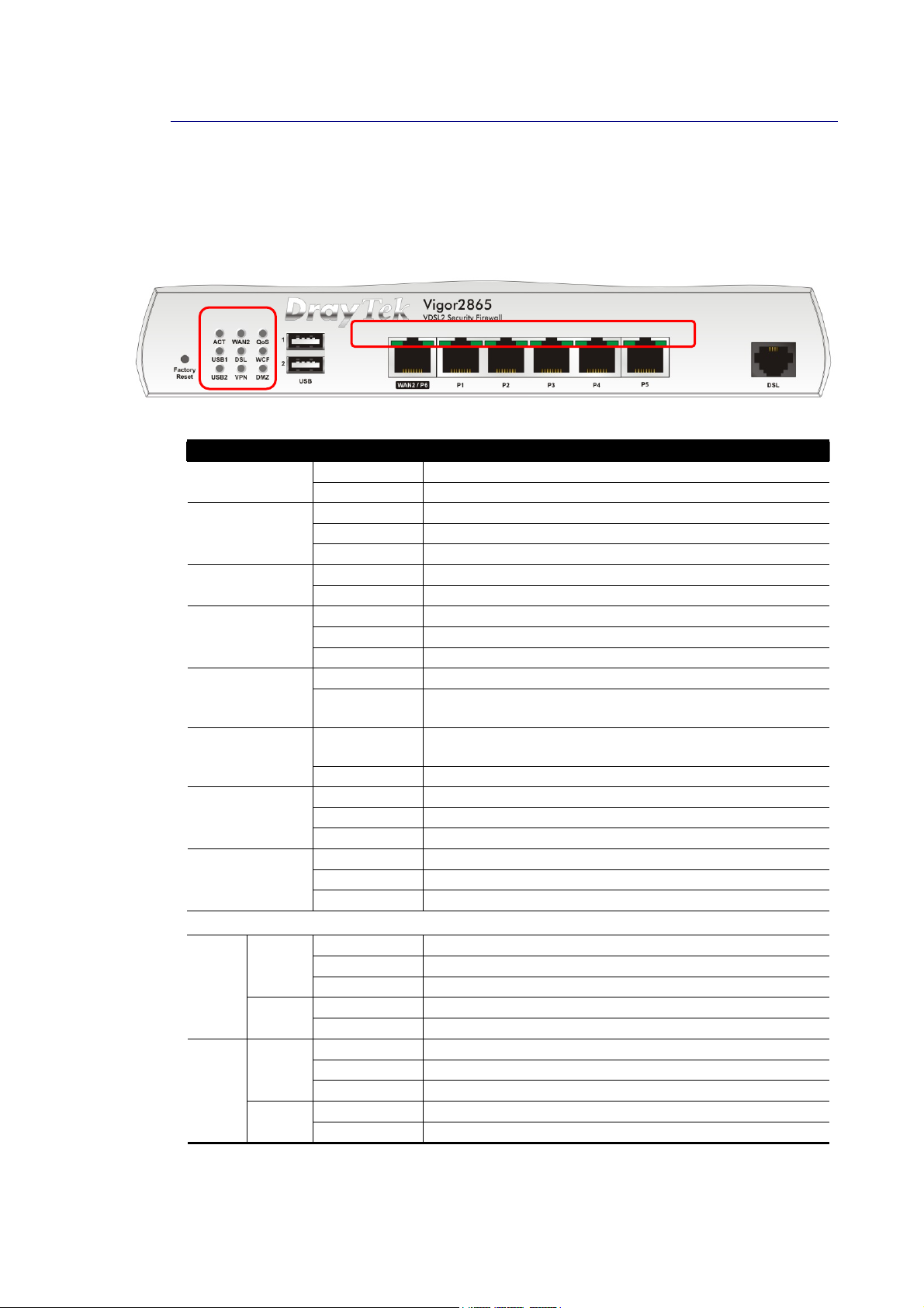
Before you use the Vigor router, please get acquainted with the LED indicators and
connectors first.
II--11--11--11 VViiggoorr22886655
LED Status Explanation
WAN2
QoS
USB1~2
DSL
WCF
VPN
DMZ
LED on Connector
Left
WAN2
/ P6
LAN
P1~P5
LED
Right
LED
Left
LED
Right
LED
Off The router is powered off. ACT
Blinking The router is powered on and running normally.
On Internet connection is ready.
Off Internet connection is not ready.
Blinking The data is transmitting.
On The QoS function is active.
Off The QoS function is inactive.
On USB device is connected and ready for use.
Off No USB device is connected.
Blinking The data is transmitting.
On The router is ready to access Internet through DSL link.
Blinking Slowly: The DSL connection is ready.
On The Web Content Filter is active. (It is enabled from
Off WCF is disabled.
On The VPN tunnel is active.
Off VPN services are disabled
Blinking Traffic is passing through VPN tunnel.
On The DMZ function is enabled.
Off The DMZ function is disabled.
Blinking The data is transmitting.
On The port is connected.
Off The port is disconnected.
Blinking The data is transmitting.
On The port is connected with 1000Mbps.
Off The port is connected with 10/100Mbps
On The port is connected.
Off The port is disconnected.
Blinking The data is transmitting.
On The port is connected with 1000Mbps.
Off The port is connected with 10/100Mbps
Quickly: The DSL connection is establishing.
Firewall >> General Setup).
The port “WAN2 / P6” is switchable. It can be used for LAN connection or WAN connection
according to the settings configured in WUI.
2
Vigor2865 Series User’s Guide
Page 17
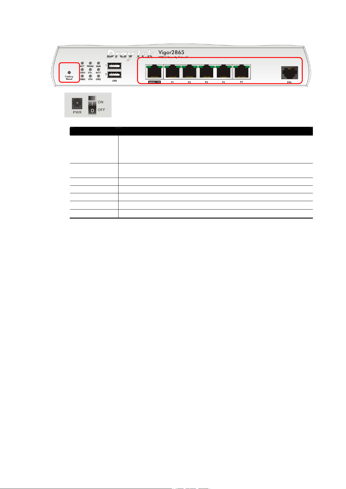
Switch on Rear Side
Interface Description
Factory Reset Restore the default settings. Usage: Turn on the router (ACT LED is
blinking). Press the hole and keep for more than 5 seconds. When you
see the ACT LED begins to blink rapidly than usual, release the button.
Then the router will restart with the factory default configuration.
USB1~2 Connecter for a USB device (for 3G/4G USB Modem or printer or
thermometer).
WAN2 / P6 Connecter for local network devices or modem for a ccessing Internet.
LAN P1-P5 Connecters for local network devices.
DSL Connecter for accessing the Internet.
PWR
ON/OFF
Connecter for a power adapter.
Power Switch.
Vigor2865 Series User’s Guide
3
Page 18
II--11--11--22 VViiggoorr22886655LL
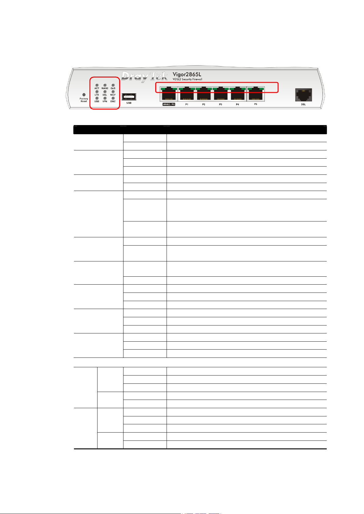
LED Status Explanation
WAN2
QoS
LTE
DSL
WCF
USB
VPN
DMZ
LED on Connector
Left
WAN2
/ P6
LAN
P1~P5
LED
Right
LED
Left
LED
Right
LED
Off The router is powered off. ACT
Blinking The router is powered on and running normally.
On Internet connection is ready.
Off Internet connection is not ready.
Blinking The data is transmitting.
On The QoS function is active.
Off The QoS function is inactive.
On LTE device is connected and ready for use.
Off LTE device is not detected, or has serious problem
(e.g., no SIM card, SIM pin error, SIM deactivated, and
etc.).
Blinking Slowly: LTE device is in dialing up.
Quickly: The data is transmitting.
On The router is ready to access Internet through DSL link.
Blinking Slowly: The DSL connection is ready.
Quickly: The DSL connection is establishing.
On The Web Content Filter is active. (It is enabled from
Firewall >> General Setup).
Off WCF is disabled.
On USB device is connected and ready for use.
Off No USB device is connected.
Blinking The data is transmitting.
On The VPN tunnel is active.
Off VPN services are disabled.
Blinking Traffic is passing through VPN tunnel.
On The DMZ function is enabled.
Off The DMZ function is disabled.
Blinking The data is transmitting.
On The port is connected.
Off The port is disconnected.
Blinking The data is transmitting.
On The port is connected with 1000Mbps.
Off The port is connected with 10/100Mbps
On The port is connected.
Off The port is disconnected.
Blinking The data is transmitting.
On The port is connected with 1000Mbps.
Off The port is connected with 10/100Mbps
4
Vigor2865 Series User’s Guide
Page 19
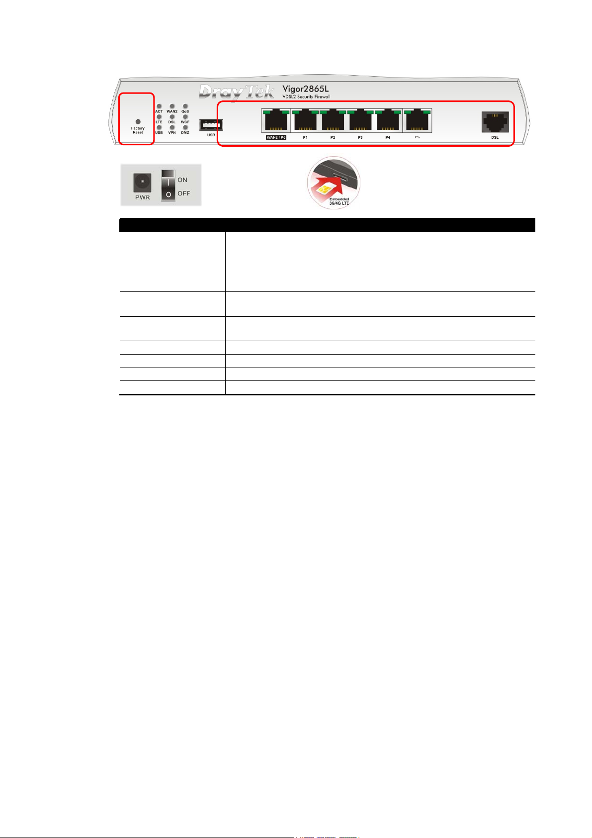
Switch on Rear Side
Interface Description
Factory Reset Restore the default settings. Usage: Turn on the router (ACT LED
is blinking). Press the hole and keep for more than 5 seconds.
When you see the ACT LED begins to blink rapidly than usual,
release the button. Then the router will restart with the factory
default configuration.
USB Connecter for a USB device (for 3G/4G USB Modem or printer or
thermometer).
WAN2 / P6 Connecter for local network devices or modem for accessing
Internet.
LAN P1~P5 Connecters for local network devices.
DSL Connecter for accessing the Internet.
PWR Connecter for a power adapter.
ON/OFF Power Switch.
The port “WAN2 / P6” is switchable. It can be used for LAN connection or WAN connection
according to the settings configured in WUI.
Vigor2865 Series User’s Guide
5
Page 20
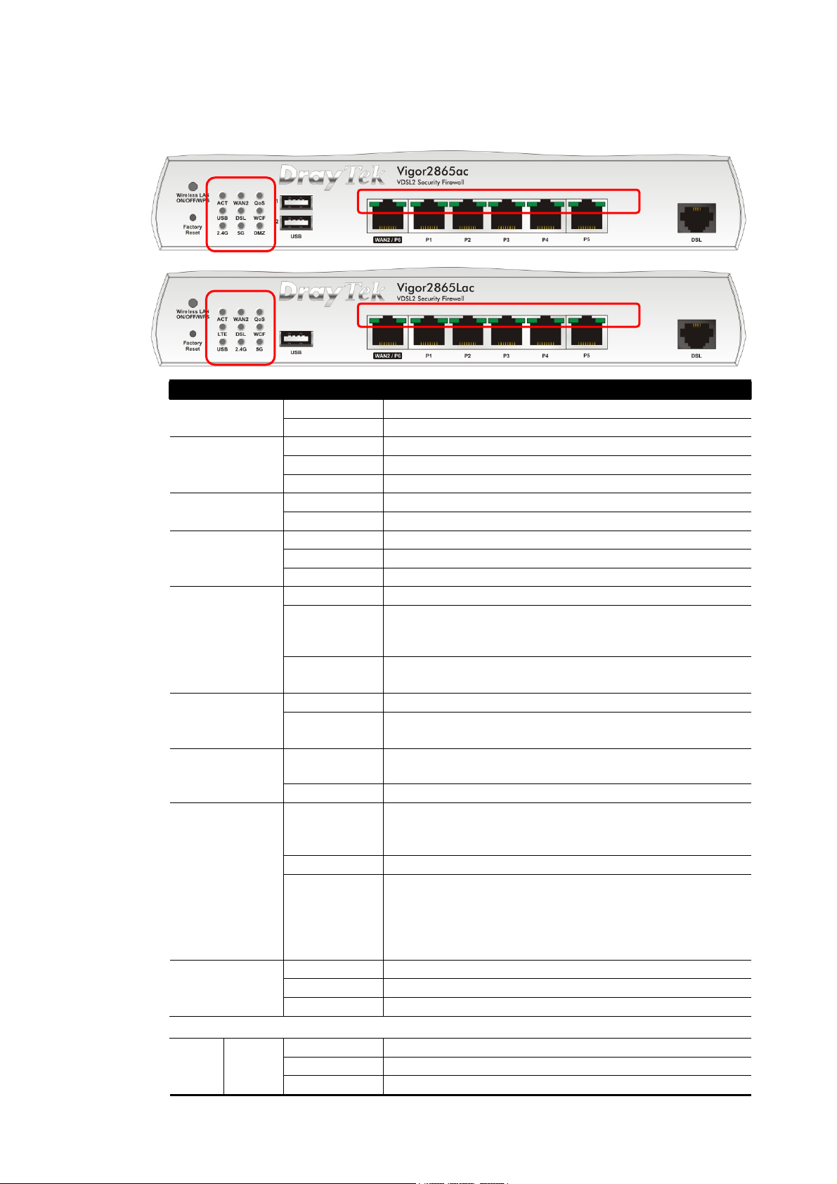
II--11--11--33 VViiggoorr22886655aacc // VViiggoorr22886655LLaacc
LED Status Explanation
Off The router is powered off. ACT
Blinking The router is powered on and running normally.
WAN2
QoS
USB
LTE
DSL
WCF
2.4G/5G
DMZ
LED on Connector
Left
WAN2
/ P6
LED
On Internet connection is ready.
Off Internet connection is not ready.
Blinking The data is transmitting.
On The QoS function is active.
Off The QoS function is inactive.
On USB device is connected and ready for use.
Off No USB device is connected.
Blinking The data is transmitting.
On LTE device is connected and ready for use.
Off LTE device is not detected, or has serious problem
Blinking Slowly: LTE device is in dialing up.
On The router is ready to access Internet through DSL link.
Blinking Slowly: The DSL connection is ready.
On The Web Content Filter is active. (It is enabled from
Off WCF is disabled.
On
Off Wireless function is disabled.
Blinking
On The DMZ function is enabled.
Off The DMZ function is disabled.
Blinking The data is transmitting.
On The port is connected.
Off The port is disconnected.
Blinking The data is transmitting.
(e.g., no SIM card, SIM pin error, SIM deactivated, and
etc.).
Quickly: The data is transmitting.
Quickly: The DSL connection is establishing.
Firewall >> General Setup).
2.4G/5G: Wireless access point with bandwidth of
2.4GHz/5GHz is ready.
WLAN: Wireless access point is ready.
It will blink slowly while wireless traffic goes through.
ACT and WLAN LEDs blink quickly and simultaneously
when WPS is working, and will return to normal
condition after two minutes. (You need to setup WPS
within 2 minutes.)
6
Vigor2865 Series User’s Guide
Page 21
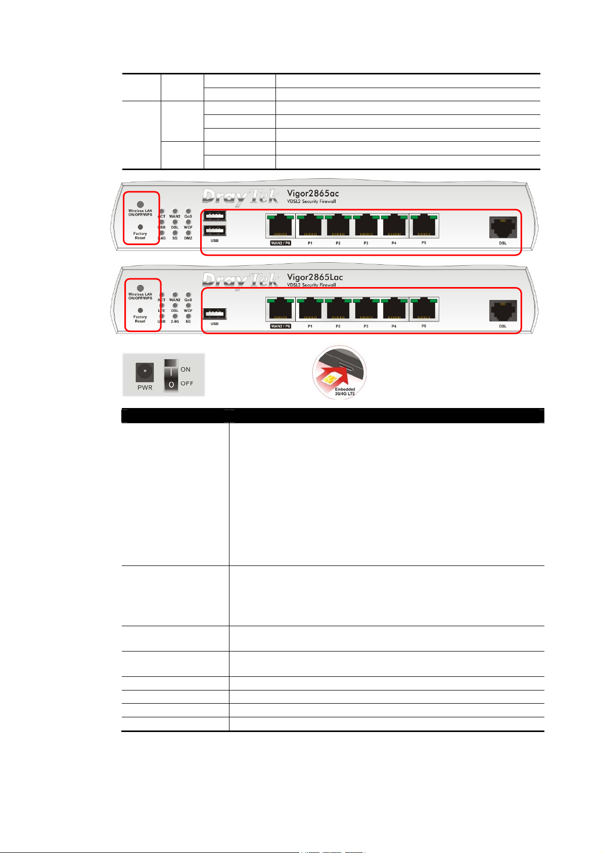
LAN
P1~P5
Right
LED
Left
LED
Right
LED
On The port is connected with 1000Mbps.
Off The port is connected with 10/100Mbps
On The port is connected.
Off The port is disconnected.
Blinking The data is transmitting.
On The port is connected with 1000Mbps.
Off The port is connected with 10/100Mbps
Switch on Rear Side (Available for Vigor2865Lac)
Interface Description
Wireless LAN
ON/OFF/WPS
Wireless band will be switched /changed according to the button
pressed and released. For example,
2.4G (On) and 5G (On) – in default.
2.4G (Off) and 5G (On) – pressed and released the button once.
2.4G (On) and 5G (Off) – pressed and released the button
twice.
2.4G (Off) and 5G (Off) – pressed and released the button three
times.
When WPS function is enabled by web user interface, press this
button for mor e t h a n 2 seconds to wait for cl ient’s device m aki ng
network connection through WPS.
Factory Reset Restore the default settings. Usage: Turn on the router (ACT LED
is blinking). Press the hole and keep for more than 5 seconds.
When you see the ACT LED begins to blink rapidly than usual,
release the button. Then the router will restart with the factory
default configuration.
USB 1~2 / USB Connecter for a USB device (for 3G/4G USB Modem or printer or
thermometer).
WAN2 / P6 Connecter for local network devices or modem for accessing
Internet.
LAN P1~P5 Connecters for local network devices.
DSL Connecter for accessing the Internet.
PWR Connecter for a power adapter.
ON/OFF Power Switch.
The port “WAN2 / P6” is switchable. It can be used for LAN connection or WAN connection
according to the settings configured in WUI.
Vigor2865 Series User’s Guide
7
Page 22
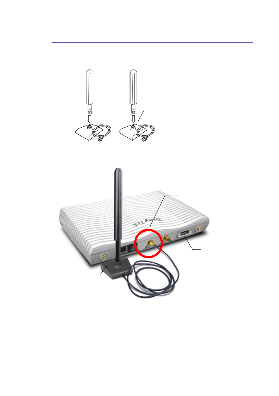
“
L
II--11--22 NNootteess ffoorr AAnntteennnnaa IInnssttaallllaattiioonn ((ffoorr
Magnetic antenna must be installed on the extension base before connecting to Vigor router.
Extension Base
There are two mounting holes for installing antennas with extension base on Vigor router.
Please install them as shown below.
“
L
”
”
mmooddeel
l))
Major Signal
Transmitted Hole
SIM Card
Slot
Extension
Base
Note, if only one antenna shall be installed, please use the mounting hole (major signal
transmitted hole) near to the power switch.
8
Vigor2865 Series User’s Guide
Page 23
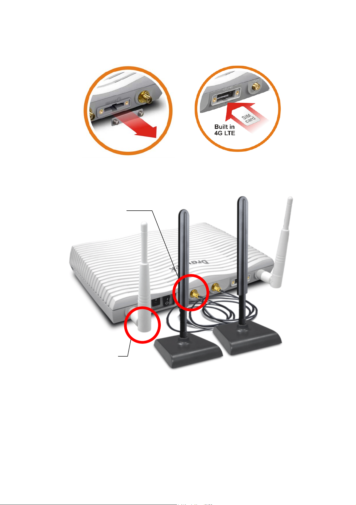
While installing the SIM card into the card slot, note that back plate of the SIM card slot must
be removed first and the direction of card notch must be on the left side.
There are two types of antennas provided for Vigor2865Lac, which must be installed in
different locations carefully and correctly. Wrong installation might cause bad signal of
wireless connection. Therefore, pay attention to the i n s t al l a t i o n o f an t e n n a s b y r ef e r r i n g t o t he
following illustration.
SMA jack for LTE Antenna (with
extension base)
SMA jack for WLAN
Antenna
Vigor2865 Series User’s Guide
9
Page 24
II--22 HHaarrddwwaarree IInnssttaallllaattiioonn
II--22--11 IInnssttaalllliinngg VViiggoorr RRoouutteerr
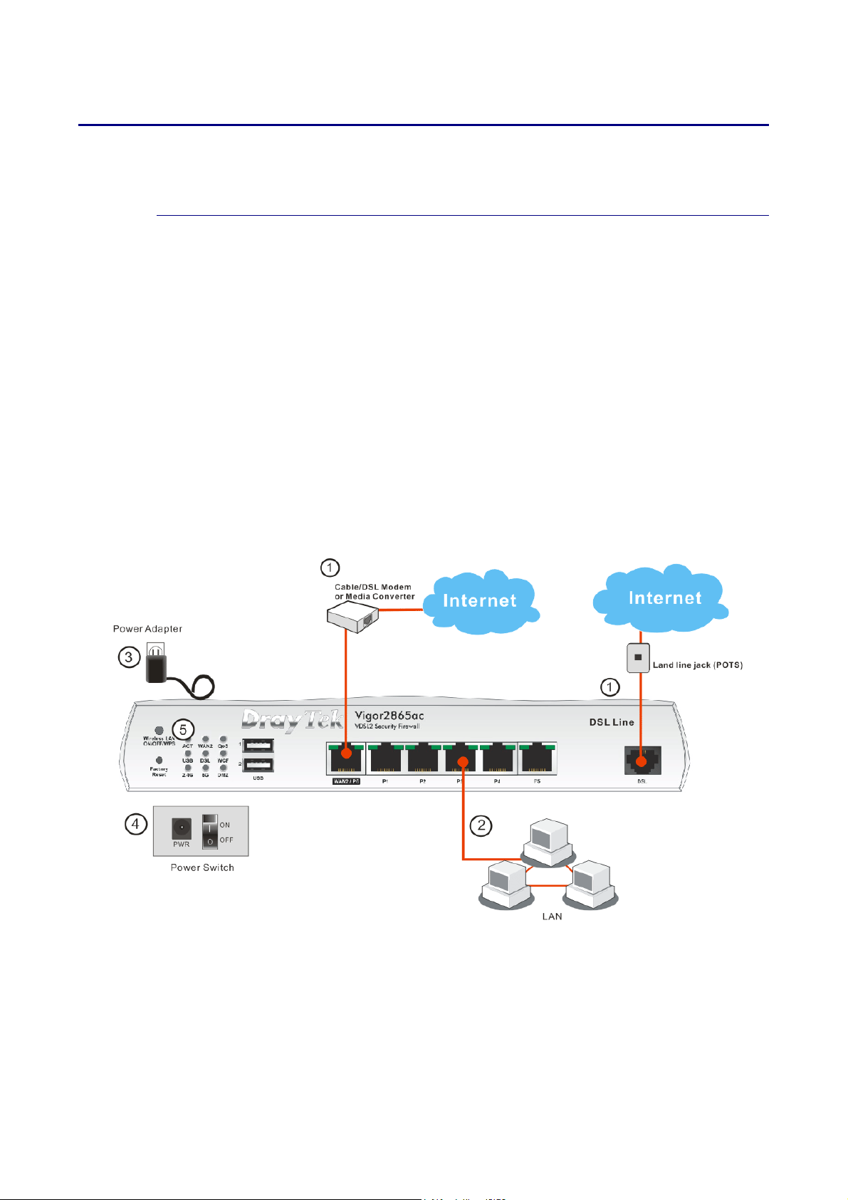
Before starting to configure the router, you have to connect your devices correctly. (For the
hardware connection, we take “ac” model as an example.)
1. Connect the DSL interface to the land line jack with a DSL line cable.
Connect the cable Modem/DSL Modem/Media Converter to the WAN port of router with
Ethernet cable (RJ-45).
2. Connect one end of an Ethernet cable (RJ-45) to one of the LAN ports of the router and
the other end of the cable (RJ-45) into the Ethernet port on your computer.
3. Connect one end of the power adapter to the router’s power port on the rear panel, and
the other side into a wall outlet.
4. Power on the device by pressing down the power switch on the rear panel.
5. The system starts to initiate. After completing the system test, the ACT LED will light up
and start blinking.
(For the hardware connection, we take “ac” model as an example.)
10
Vigor2865 Series User’s Guide
Page 25
II--22--22 WWaallll--MMoouunntteedd IInnssttaallllaattiioonn
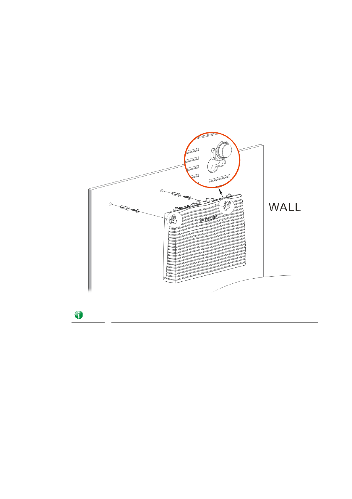
Vigor router has keyhole type mounting slots on the underside.
1. A template is provided on the Vigor router packaging box to enable you to space the
screws correctly on the wall.
2. Place the template on the wall and drill the holes according to the recommended
instruction.
3. Fit screws into the wall using the appropriate type of wall plug.
Info
4. When you finished about procedure, the router has been mounted on the wall firmly.
The recommended drill diameter shall be 6.5mm (1/4”).
Vigor2865 Series User’s Guide
11
Page 26
II--22--33 IInnssttaalllliinngg UUSSBB PPrriinntteerr ttoo VViiggoorr RRoouutteerr
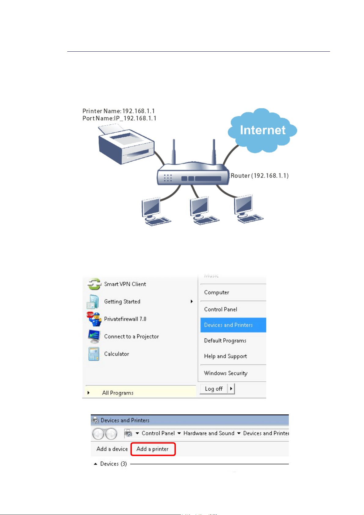
You can install a printer onto the router for sharing printing. All the PCs connected this router
can print documents via the router. The example provided here is made ba sed on Windows 7.
For other Windows system, please visit www.DrayTek.com.
Before using it, please follow the steps below to configure settings for connected computers
(or wireless clients).
1. Connect the printer with the router through USB/parallel port.
2. Open All Programs>>Getting Started>>Devices and Printers.
3. Click Add a printer.
12
Vigor2865 Series User’s Guide
Page 27
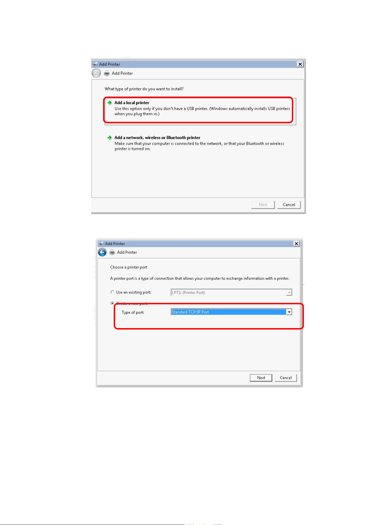
4. A dialog will appear. Click Add a local printer and click Next.
5. In this dialog, choose Create a new port. In the field of Type of port, use the drop down
list to select Standard TCP/IP Port. Then, click Next.
Vigor2865 Series User’s Guide
13
Page 28
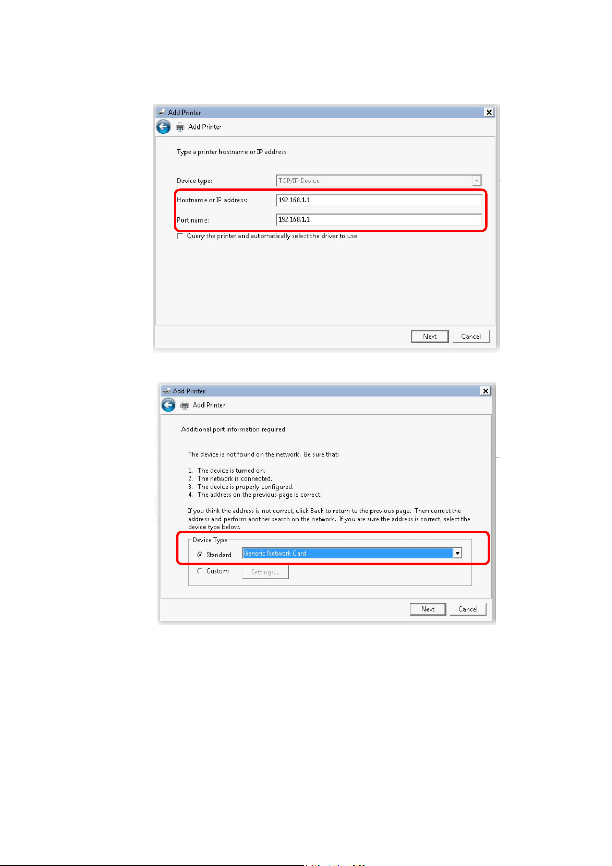
4
6. In the following dialog, type 192.168.1.1 (router’s LAN IP) in the field of Hostname or
IP Address and type 192.168.1.1 as the Port name. Then, click Next.
7. Click Standard and choose Generic Network Card.
1
Vigor2865 Series User’s Guide
Page 29
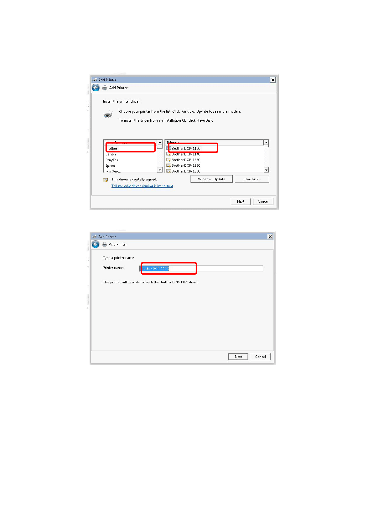
8. Now, your system will ask you to choose right name of the printer that you installed onto
the router. Such step can make correct driver loaded onto your PC. When you finish the
selection, click Next.
9. Type a name for the chosen printer. Click Next.
Vigor2865 Series User’s Guide
15
Page 30
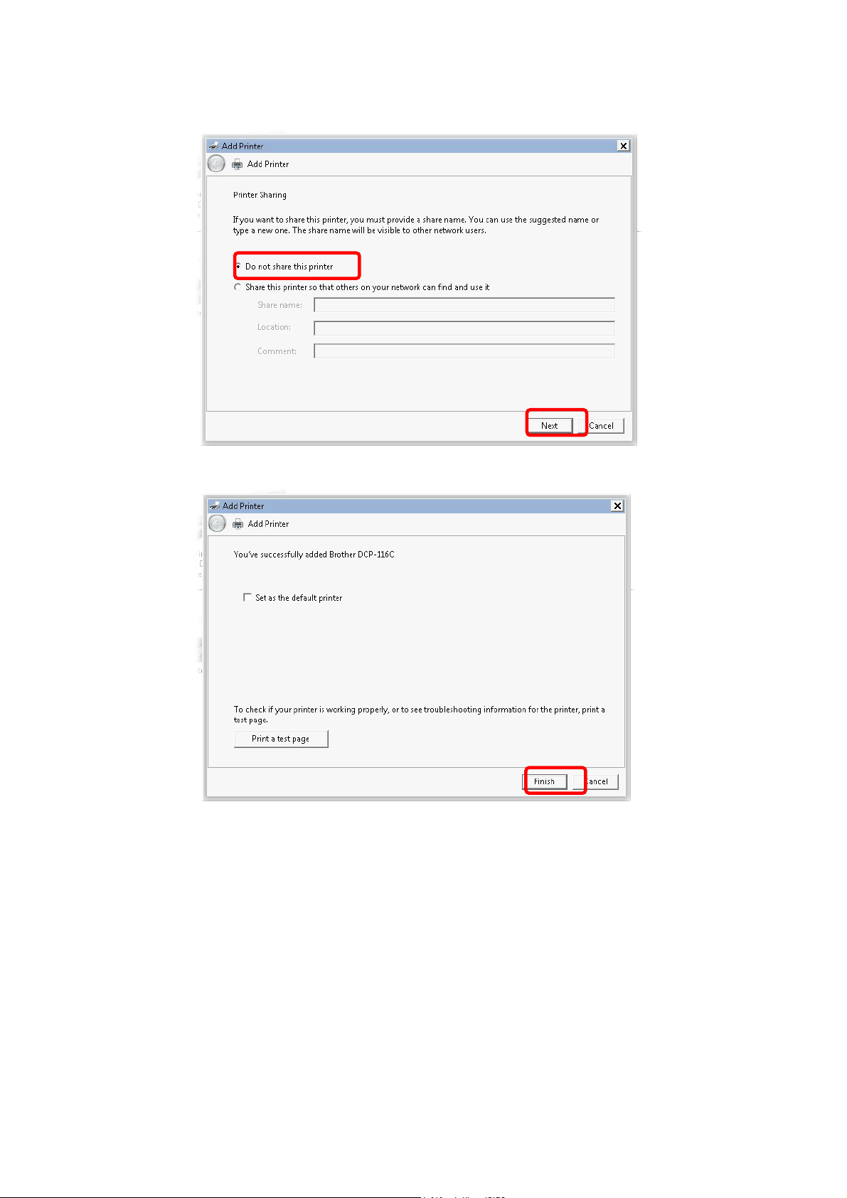
10. Choose Do not share this printer and click Next.
11. Then, in the following dialog, click Finish.
16
Vigor2865 Series User’s Guide
Page 31
7
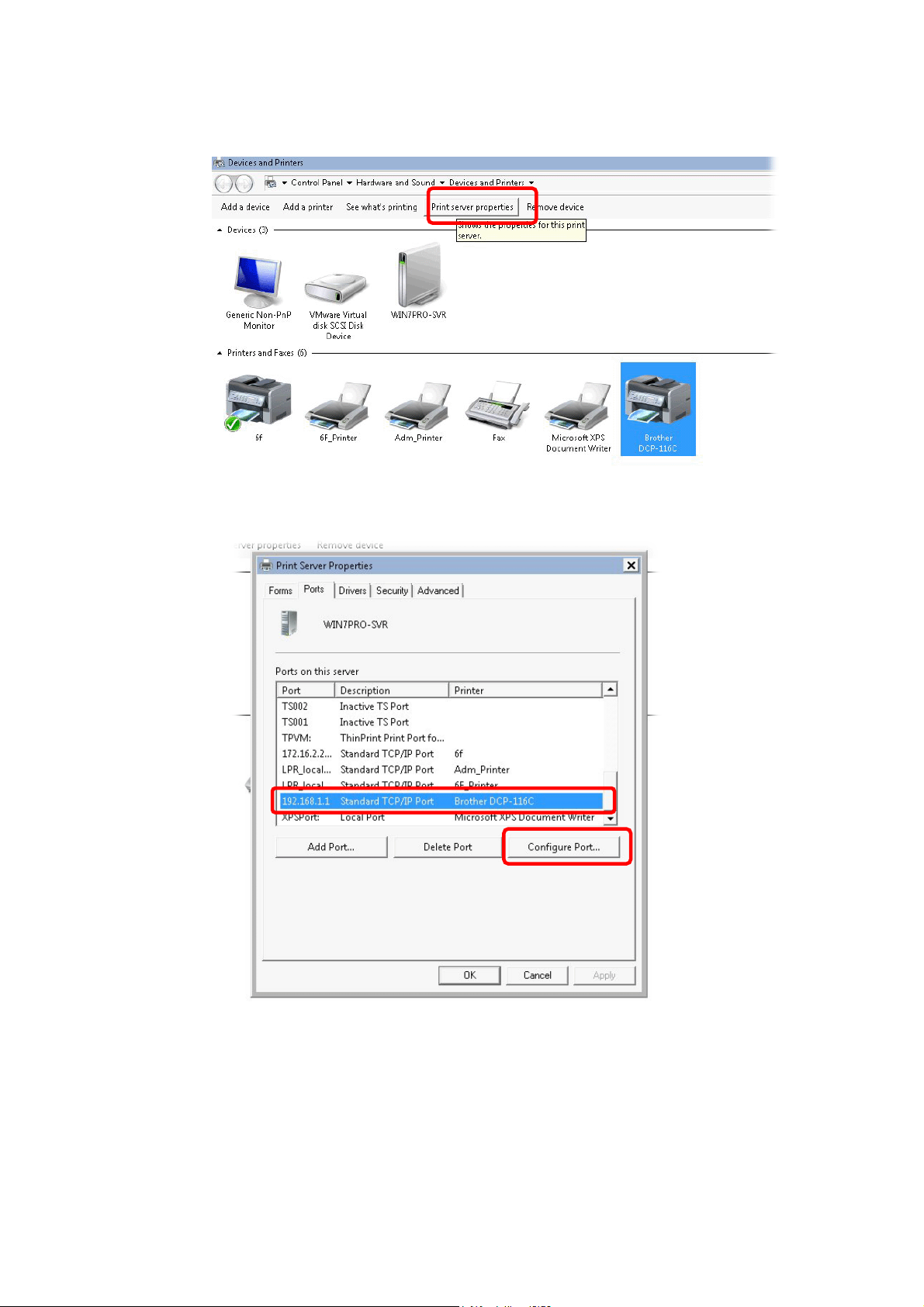
12. The new printer has been added and displayed under Printers and Faxes. Click the new
printer icon and click Printer server properties.
13. Edit the property of the new printer you have added by clicking Configure Port.
Vigor2865 Series User’s Guide
1
Page 32
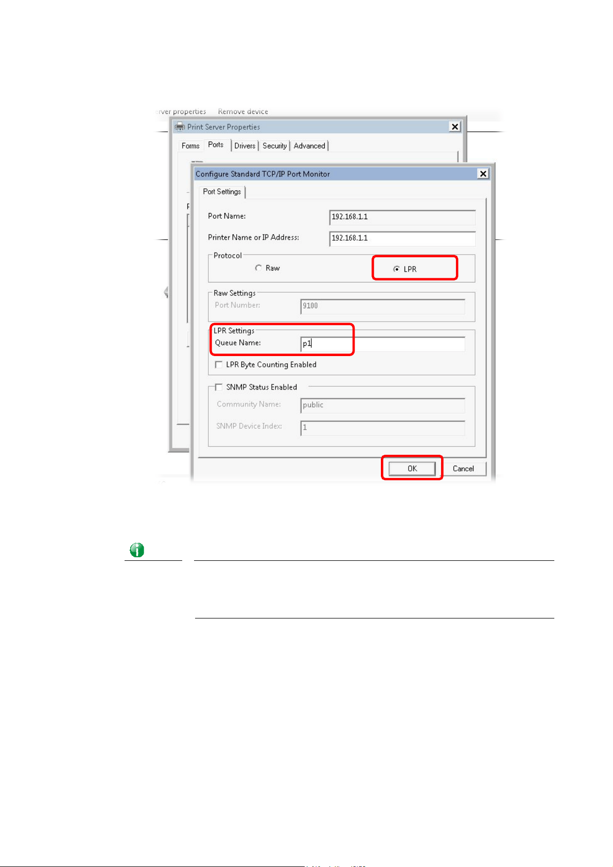
14. Select "LPR" on Protocol, type p1 (number 1) as Queue Name. Then click OK. Next
please refer to the red rectangle for choosing the correct protocol and LPR name.
The printer can be used for printing now. Most of the printers with different manufacturers
are compatible with vigor router.
Info
Some printers with the fax/scanning or other additional functions are not
supported.
Vigor router supports printing request from computers via LAN ports but not
WAN port.
18
Vigor2865 Series User’s Guide
Page 33
II--33 AAcccceessssiinngg WWeebb PPaaggee
1. Make sure your PC connects to the router correctly.
You may either simply set up your computer to get IP dynamically from the router or set
up the IP address of the computer to be the same subnet as the default IP address of
Vigor router 192.168.1.1. For the detailed information, please refer to the later
section - Trouble Shooting of the guide.
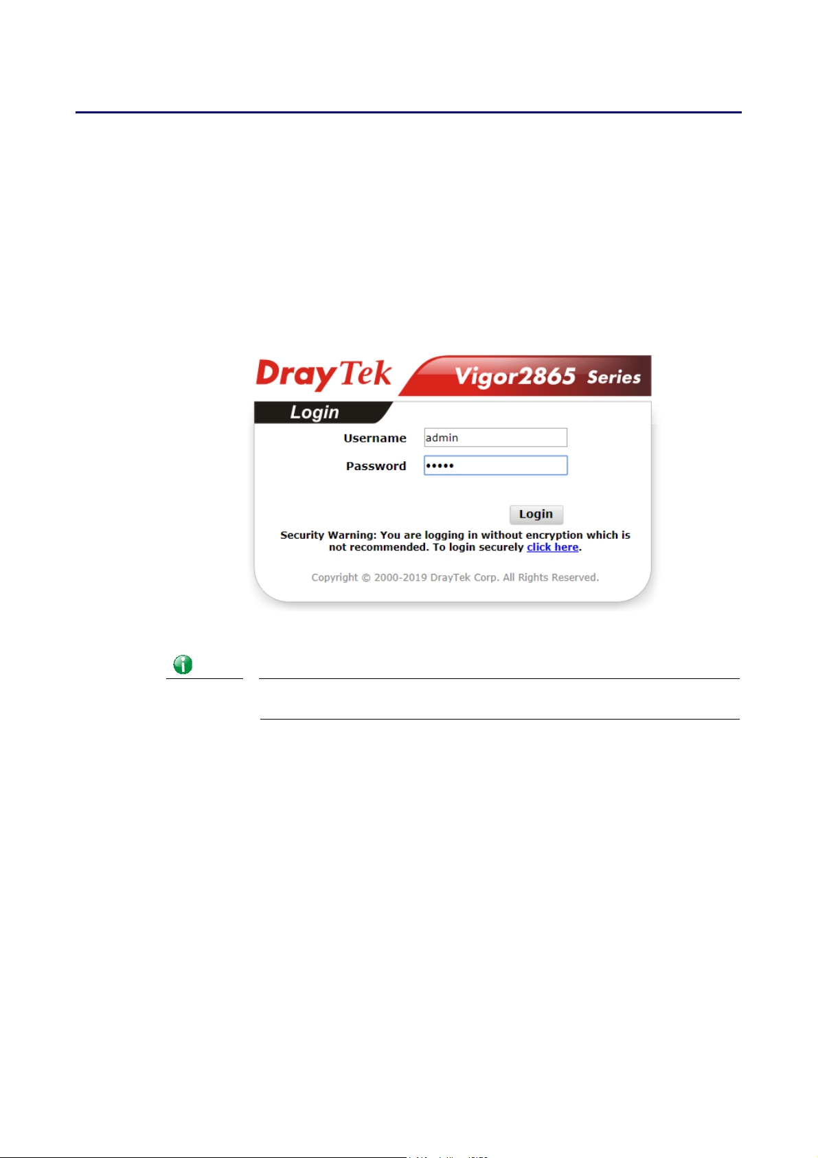
2. Open a web browser on your PC and type http://192.168.1.1. The following window
will be open to ask for username and password.
3. Please type “admin/admin” as the Username/Password and click Login.
Info
If you fail to access to the web configuration, please go to “Trouble
Shooting” for detecting and solving your problem.
Vigor2865 Series User’s Guide
19
Page 34
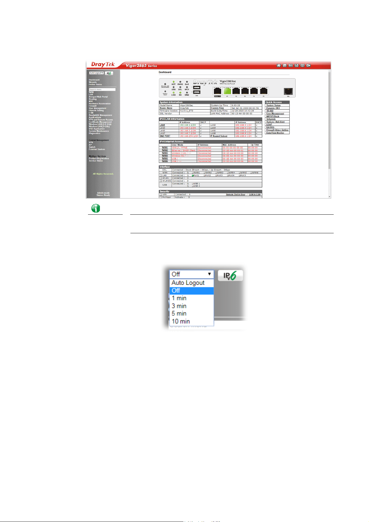
4. Now, the Main Screen will appear. Take Vigor2865ac as an example.
Info
The home page will be different slightly in accordance with the type of
the router you have.
5. The web page can be logged out according to the chosen condition. The default setting
is Auto Logout, which means the web configuration system will logout after 5 minutes
without any operation. Change the setting for your necessity.
20
Vigor2865 Series User’s Guide
Page 35
II--44 CChhaannggiinngg PPaasssswwoorrdd
Please change the password for the original security of the router.
1. Open a web browser on your PC and type http://192.168.1.1. A pop-up window will
open to ask for username and password.
2. Please type “admin/admin” as Username/Password for acce ssing into the web user
interface with admin mode.
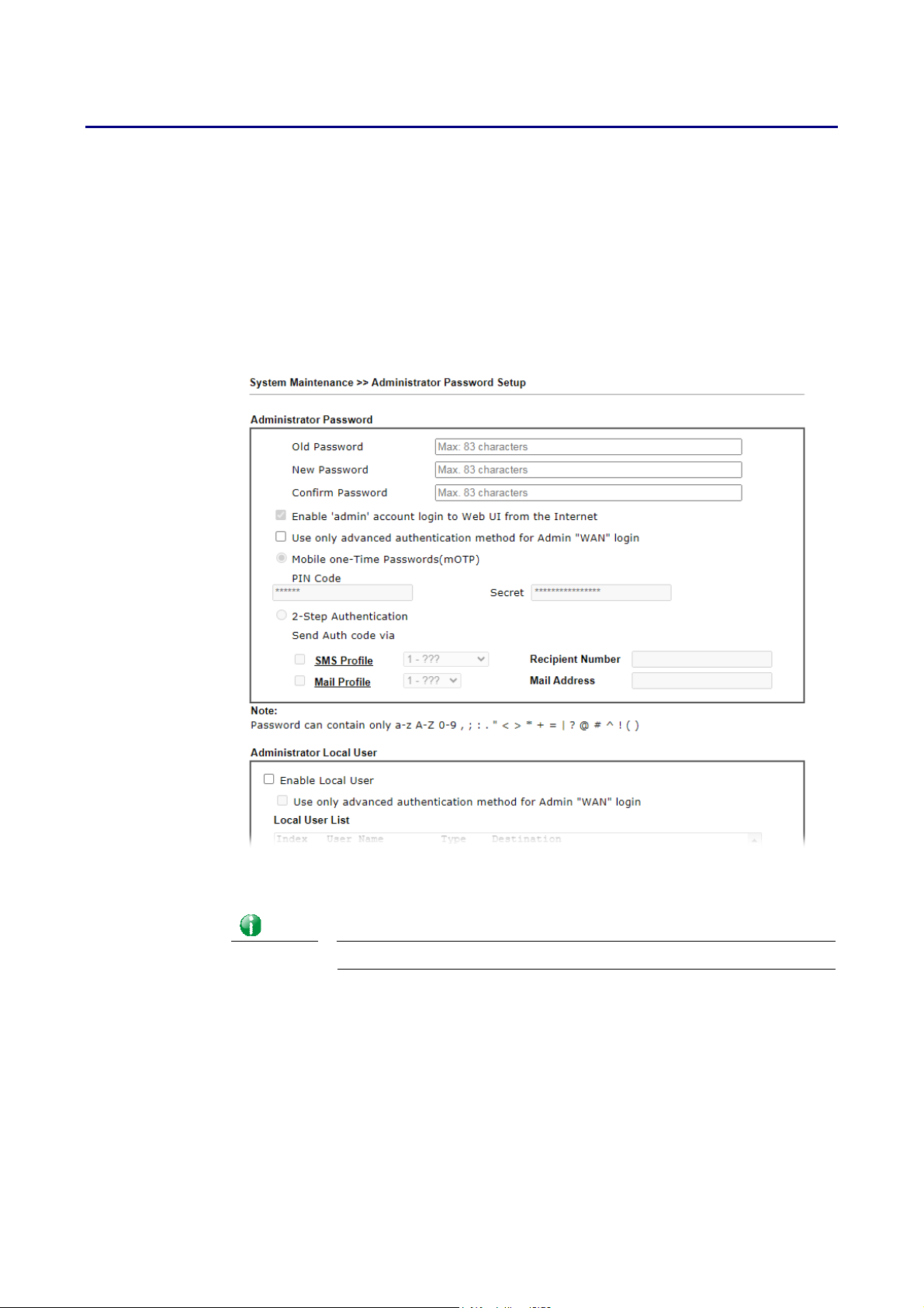
3. Go to System Maintenance page and choose Administrator Password.
4. Enter the login password (the default is “admin”) on the field of Old Password. Type
New Password and Confirm Password. Then click OK to continue.
Info
Vigor2865 Series User’s Guide
The maximum length of the password you can set is 23 characters.
21
Page 36
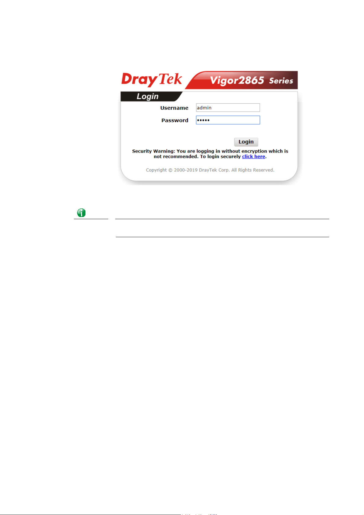
5. Now, the password has been changed. Next time, use the new password to access the
Web user interface for this router.
Info
Even the password is changed, the Username for logging onto the web user
interface is still “admin”.
22
Vigor2865 Series User’s Guide
Page 37
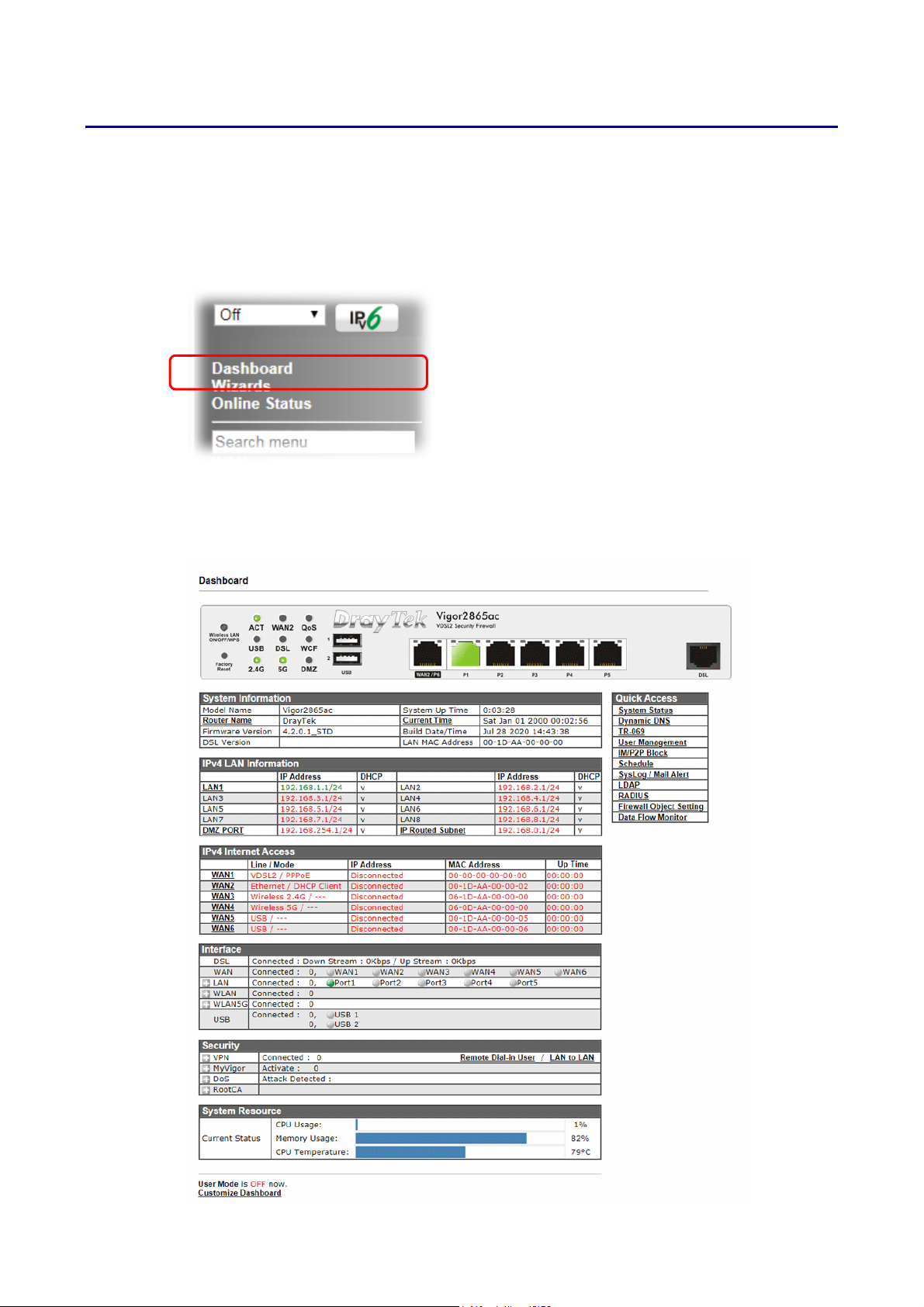
II--55 DDaasshhbbooaarrdd
The Dashboard provides a convenient way to monitor the current status of the router,
including firmware version, system resource usage, LAN and WAN connect ion uptimes, and
interface usage. It is refreshed every 5 seconds with the latest information.
For the Dashboard is the landing page after logging into the web configuration utility, you can
also bring up the Dashboard by clicking on the Dashboard on the menu bar.
The figure below shows the Dashboard of the Vigor2865ac. The Dashboards of other Vigor2865
models are may vary slightly due to differences in features.
Vigor2865 Series User’s Guide
23
Page 38
4
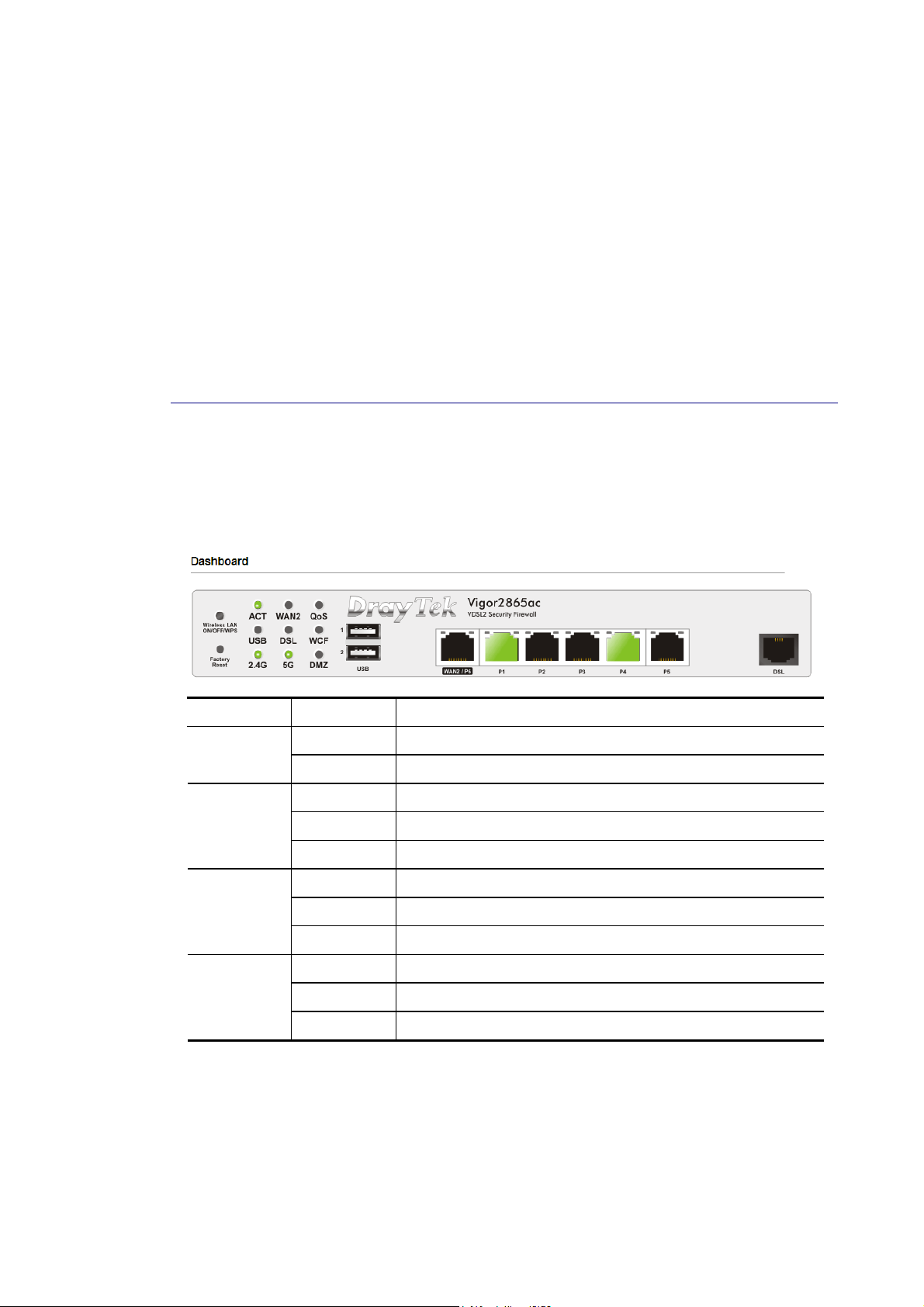
The System Information section displays general information about the router, such as system
uptime, system time, and firmware version.
The IPv4 Internet Access section shows the IPv4 connection status of the WAN ports, including
their access modes, IP addresses, MAC addresses and uptimes.
The IPv6 Internet Access section shows the IPv6 connection status of the WAN port that has
IPv6 enabled. Unlike IPv4, IPv6 support is limited to one WAN port at a time, so there is
always at most one IPv6 WAN connection shown.
The Interface section shows the physical connection status of the WAN, Ethernet, Wi-Fi and
USB interfaces.
The Security section shows the states of the security-related features, including VPN, Web
Content Filter and App Enforcement.
The System Resource section shows the current CPU and memory usage of the router.
II--55--11 VViirrttuuaall PPaanneell
At the top of the Dashboard page is the Virtual Panel, a graphical simulation of the front
panel of the router.
The WAN and LAN connectors are shaded with various colours t o i n dicate their status at any
given point in time.
Port Color Description
Black No USB device is connected. USB
Green A USB device is connected.
VDSL/ADSL
Black No VDSL/ADSL connection.
Green ADSL connection is ready.
Orange VDSL connection is ready.
WAN2/P6
LAN
1 ~ 5
For detailed information about the LED display, refer to I-1-1 LED Indicators and
Connectors.
2
Black WAN2 port is disconnected.
Green WAN2 port is connected at 1 Gbps.
Orange WAN2 port is connected at 10/100 Mbps.
Black LAN port is disconnected.
Green LAN port is connected at 1 Gbps.
Orange LAN port is connected at 10/100 Mbps.
Vigor2865 Series User’s Guide
Page 39
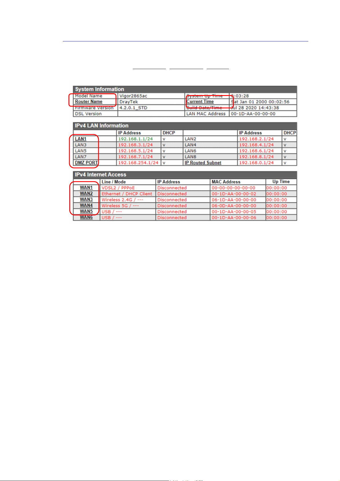
II--55--22 NNaammee wwiitthh aa LLiinnkk
A name with a link (e.g., Router Name, Current Time, WAN1~6 and etc.) below means you can
click it to open the configuration page for modification.
Vigor2865 Series User’s Guide
25
Page 40
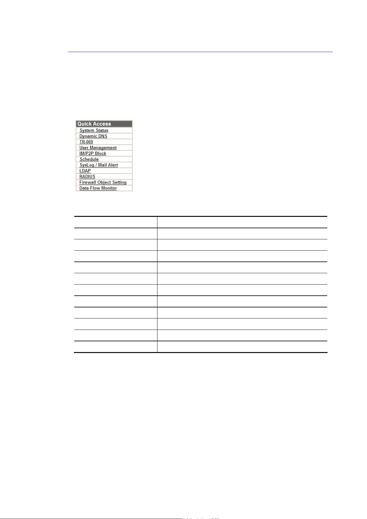
II--55--33 QQuuiicckk AAcccceessss ffoorr CCoommmmoonn UUsseedd MMeennuu
All the menu items can be accessed and arranged orderly on the left side of the main page for
your request. For your convenience, some of the most-frequently-used items in the Web
Configuration Utility are listed under the Quick Access section on the Dashboard.
Look at the right side of the Dashboard. You will find a group of common used functions
grouped under Quick Access.
Move your mouse cursor on any one of the links and click on it. The corresponding setting
page will be open immediately.
Hyperlink Destination
System Status System Maintenance >> System Status
Dynamic DNS Applications >> Dynamic DNS Setup
TR-069 System Maintenance >> TR-069 Setting
User Management User Management >> User Profile
IM/P2P Block CSM >> APP Enforcement Profile
Schedule Applications >> Schedule
SysLog / Mail Alert System Maintenance >> SysLog / Mail Alert Setup
LDAP Applications >> Active Directory /LDAP
RADIUS Applications >> RADIUS/TACACS+
Firewall Object Setting Objects Setting >> IP Object
Data Flow Monitor Diagnostics >> Data Flow Monitor
In addition, quick access for VPN security settings such as Remote Dial-in User and LAN to
LAN are located on the bottom of this page. Scroll down the page to find them and use them
if required.
26
Vigor2865 Series User’s Guide
Page 41
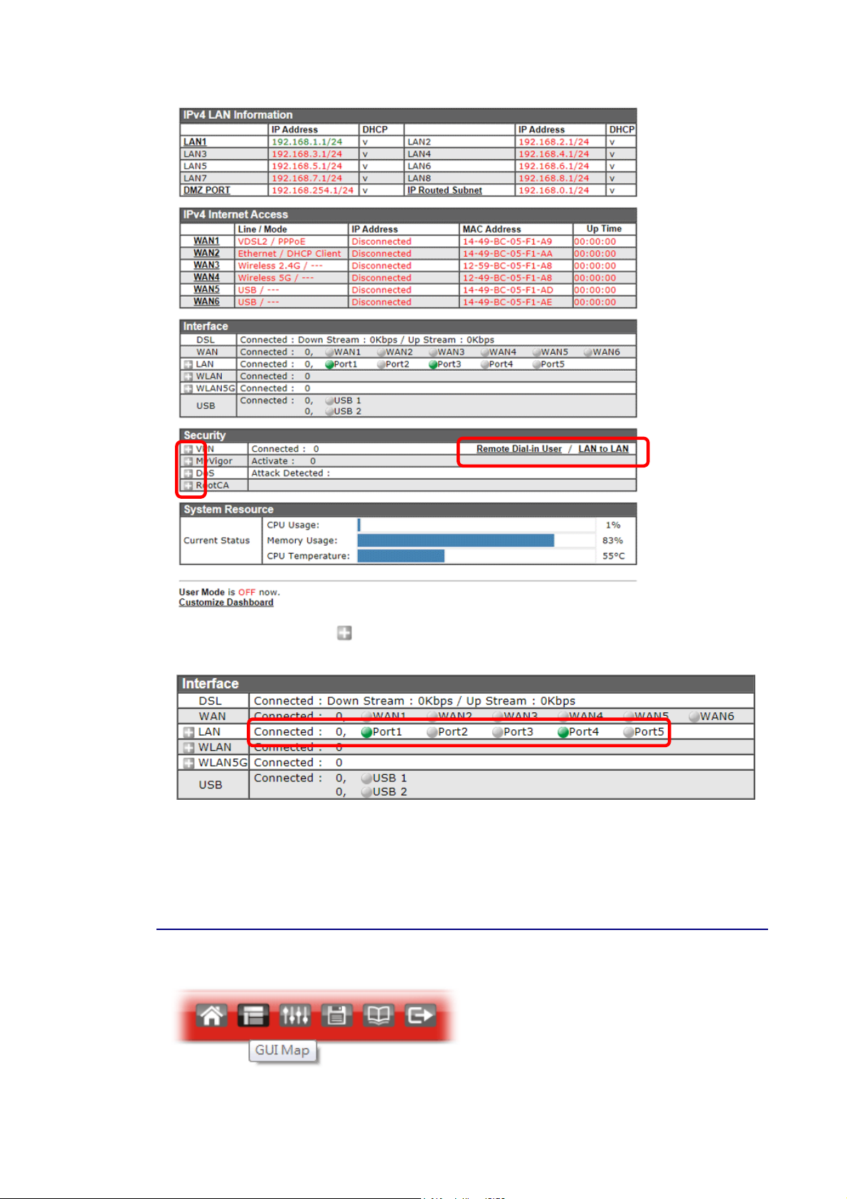
Note that there is a plus (
VPN connection(s) used presently.
Host connected physically to the router via LAN port(s) will be displayed with green circles in
the field of Connected.
All of the hosts (including wireless clients) displayed with Host ID, IP Address and MAC address
indicates that the traffic would be transmitted through LAN port(s) and then the WAN port.
The purpose is to perform the traffic monitor of the host(s).
II--55--44 GGUUII MMaapp
) icon located on the left side of VPN/LAN. Click it to review the
Vigor2865 Series User’s Guide
27
Page 42
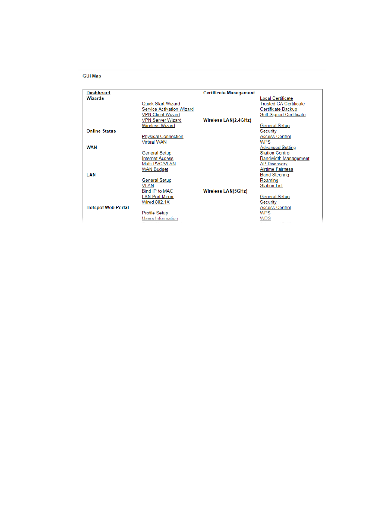
All the functions the router supports are listed with table clearly in this page. Users can click
the function link to access into the setting page of the function for detailed configuration.
Click the icon on the top of the main screen to display all the functions.
28
Vigor2865 Series User’s Guide
Page 43
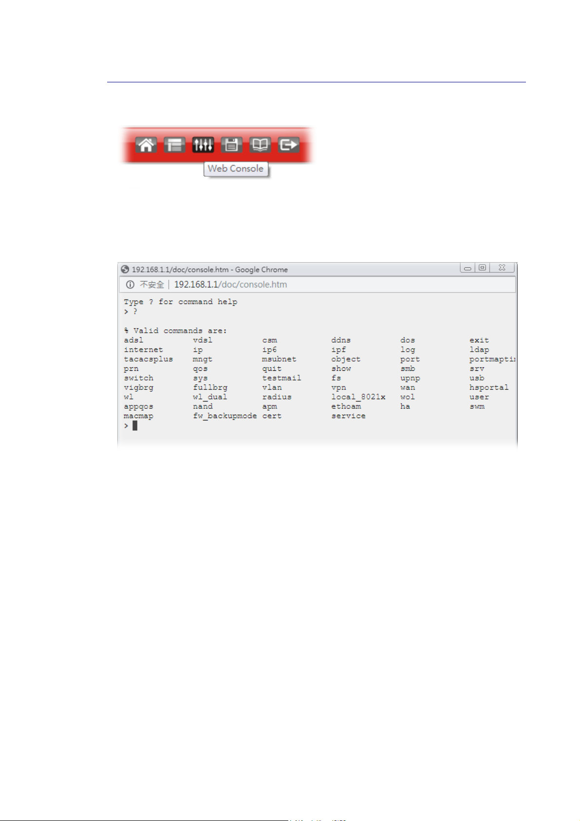
II--55--55 WWeebb CCoonnssoollee
It is not necessary to use the telnet command via DOS prompt. The changes made by using
web console have the same effects as modified through web user interface. The
functions/settings modified under Web Console also can be reviewed on the web user
interface.
Click the Web Console icon on the top of the main screen to open the following screen.
Vigor2865 Series User’s Guide
29
Page 44
II--55--66 CCoonnffiigg BBaacckkuupp
There is one way to store current used settings quickly by clicking the Config Backup icon. It
allows you to backup current settings as a file. Such configuration file can be restored by
using System Maintenance>>Configuration Backup.
II--55--77 LLooggoouutt
Click this icon to exit the web user interface.
30
Vigor2865 Series User’s Guide
Page 45
II--55--88 OOnnlliinnee SSttaattuuss
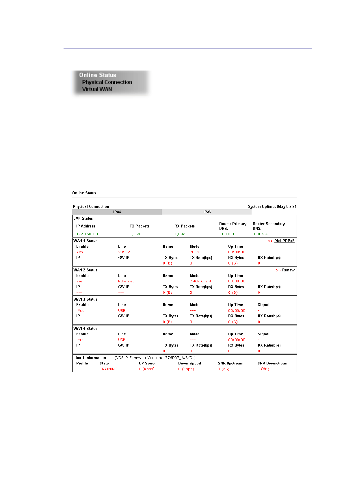
II--55--88--11 PPhhyyssiiccaall CCoonnnneeccttiioonn
The Physical Connection page displays the status of all the physical network interfaces,
including LAN, WAN and DSL.
The information shown for every interface can be in green, indicating the interface is enabled
and online; or red, indicating the interface is either disabled or offline.
PPhhyyssiiccaall CCoonnnneeccttiioonn ffoorr IIPPvv44 PPrroottooccooll
This IPv4 tab displays IPv4 related information of all the LAN and WAN interfaces, plus the DSL
connection status.
Vigor2865 Series User’s Guide
31
Page 46
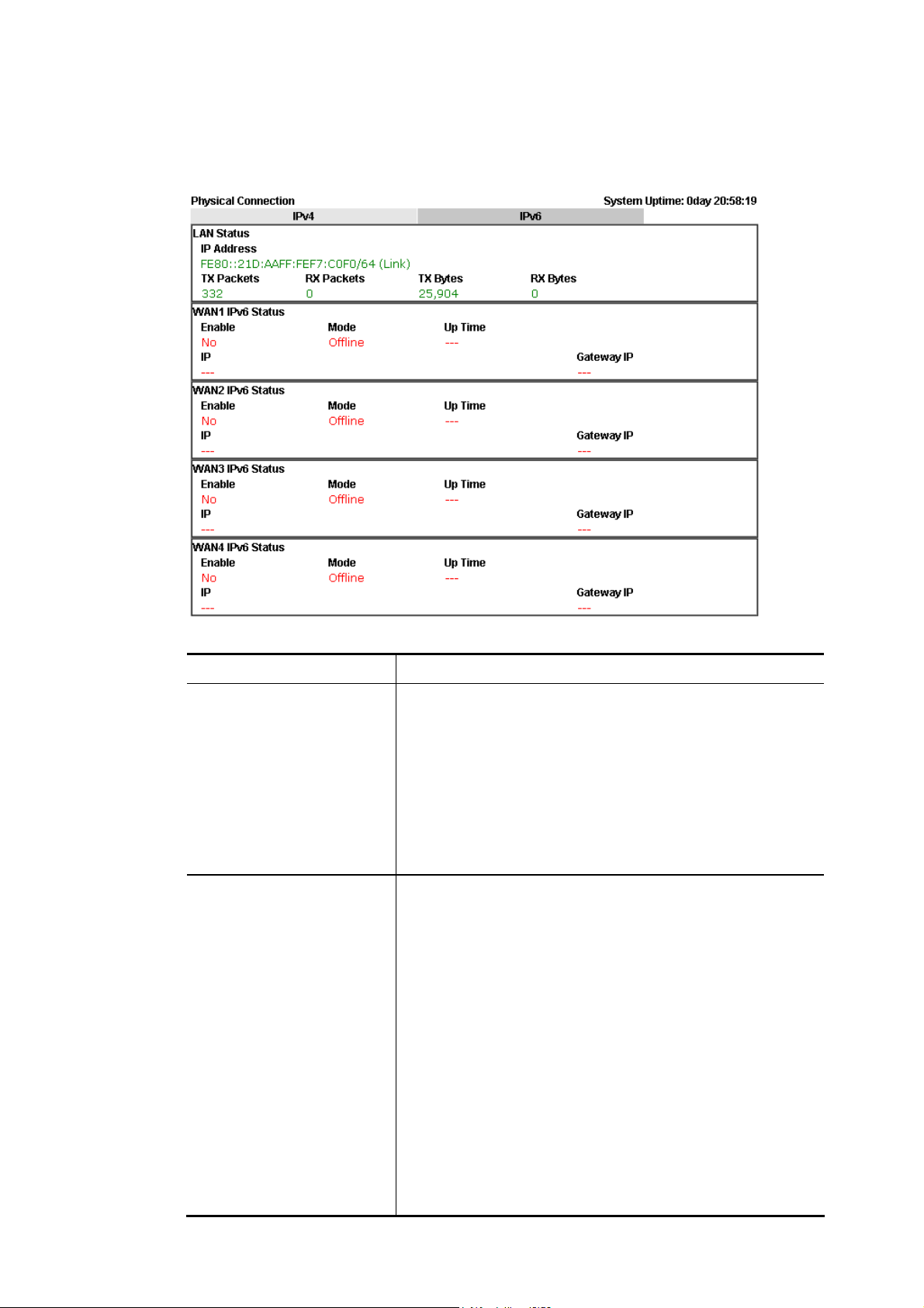
PPhhyyssiiccaall CCoonnnneeccttiioonn ffoorr IIPPvv66 PPrroottooccooll
This IPv6 tab displays IPv6 related information of all the LAN and WAN interfaces.
Detailed explanation (for IPv4) is shown below:
Item Description
LAN Status Primary DNS-Displays the primary DNS server address for
WAN interface.
Secondary DNS -Displays the secondary DNS server address
for WAN interface.
IP Address-Displays the IP address of the LAN interface.
TX Packets-Displays the total transmitted packets at the
LAN interface.
RX Packets-Displays the total received packets at the LAN
interface.
WAN1/WAN2/WAN3
/WAN4/WAN5/WAN6
Status
Enable – Yes in red means such interface is available but
not enabled. Yes in green means such interface is enabled.
Line – Displays the physical connection (VDSL, ADSL,
Ethernet, or USB) of this interface.
Name – Display the name of the router.
Mode - Displays the type of WAN connection (e.g., PPPoE).
Up Time - Displays the total uptime of the interface.
IP - Displays the IP address of the WAN interface.
GW IP - Displays the IP address of the default gateway.
TX Packets - Displays the total transmitted packets at the
WAN interface.
TX Rate - Displays the speed of transmitted octets at the
WAN interface.
RX Packets - Displays the total number of received packets
at the WAN interface.
RX Rate - Displays the speed of received octets at the WAN
32
Vigor2865 Series User’s Guide
Page 47
Item Description
interface.
Detailed explanation (for IPv6) is shown below:
Item Description
LAN Status IP Address- Displays the IPv6 address of the LAN interface..
TX Packets-Displays the total transmitted packets at the LAN
interface.
RX Packets-Displays the total received packets at the LAN
interface.
TX Bytes - Displays the speed of transmitted octets at the
LAN interface.
RX Bytes - Displays the speed of received octets at the LAN
interface.
WAN IPv6 Status Enable – No in red means such interface is available but not
enabled. Yes in green means such inte rface is enabled. No in
red means such interface is not available.
Mode - Displays the type of WAN connection (e.g., TSPC).
Up Time - Displays the total uptime of the interface.
IP - Displays the IP address of the WAN interface.
Gateway IP - Displays the IP address of the default gateway.
Info
The words in green mean that the WAN connection of that interface is ready
for accessing Internet; the words in red mean that the WAN connection of
that interface is not ready for accessing Internet.
II--55--88--22 VViirrttuuaall WWAANN
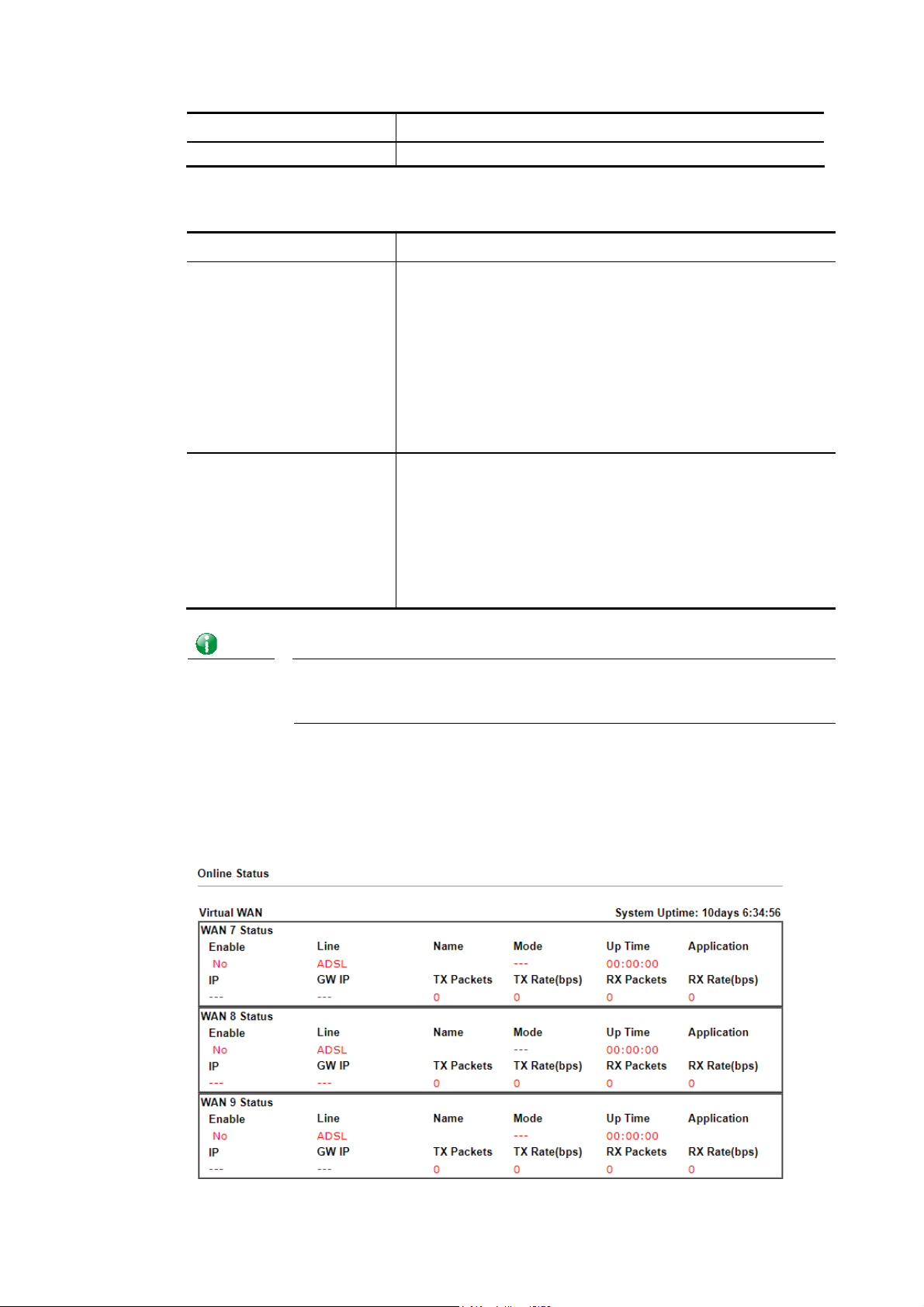
The Virtual WAN screen displays the status of the 3 virtual WAN interfaces.
Virtual WAN are used by TR-069 management, VoIP service and so on.
The field of Application will list the purpose of such WAN connection.
Vigor2865 Series User’s Guide
33
Page 48

4
Detailed explanation is shown below:
Item Description
Enable Yes- Virtual WAN interface is enabled.
No- Virtual WAN interface is disabled.
Line The WAN port and connection mode used for this virtual
WAN.
ADSL- ADSL mode on WAN1.
VDSL- VDSL mode on WAN1.
Ethernet(WAN2)- The Ethernet WAN2 port is used for this
Name The IPv6 addresses of the WAN interface. The global address
is routable whereas the link local address is for LAN use only.
Mode Gateway address of the IPv6 WAN connection.
Up Time Yes: IPv6 support on the WAN interface is enabled.
No: IPv6 support on the WAN interface is disabled.
Application The IPv6 access mode, which can be one of Offline, PPP,
TSPC, AICCU, DHCPv6 Client, Static IPv6, 6in4 Static Tunnel,
and 6rd.
IP The IPv6 addresses of the WAN interface. The global address
is routable whereas the link local address is for LAN use only.
GW IP Gateway address of the IPv6 WAN connection.
TX Packets Total number of IPv6 packets leaving the WAN interface.
TX Rate(Bps) The speed of transmitted octets.
RX Packets Total number of IPv6 packets received by the WAN interface.
RX Rate(Bps) The speed of received octets.
3
Vigor2865 Series User’s Guide
Page 49
II--66 QQuuiicckk SSttaarrtt WWiizzaarrdd
The Quick Start Wizard allows you to quickly and easily set the router up for Internet access.
Note that only one specific WAN interface can be configured each time the wizard is run. If
you have additional WAN interfaces to configure, rerun the wizard and select the appropriate
WAN interface. As an alternative, you may use the WAN menu item.
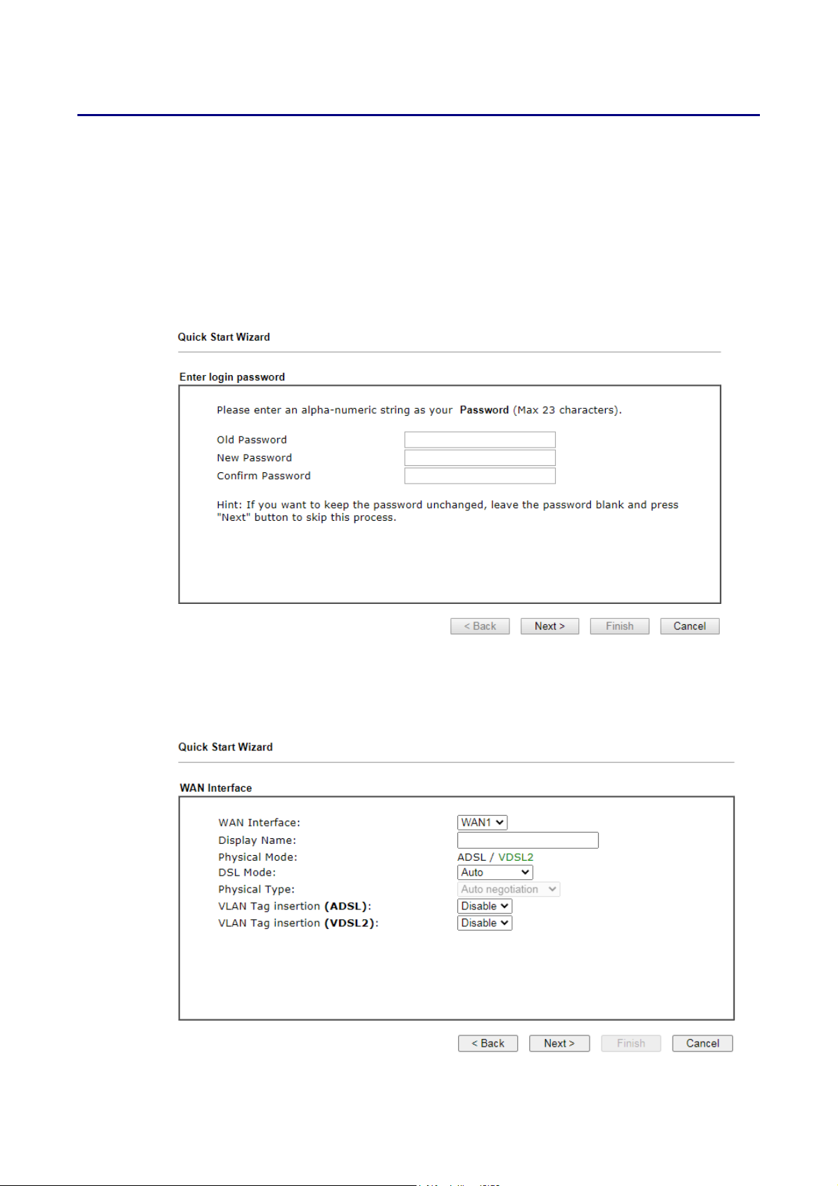
Go to Wizards>>Quick Start Wizard. The first screen of Quick Start Wizard is entering login
password. After entering the password, please click Next to proceed.
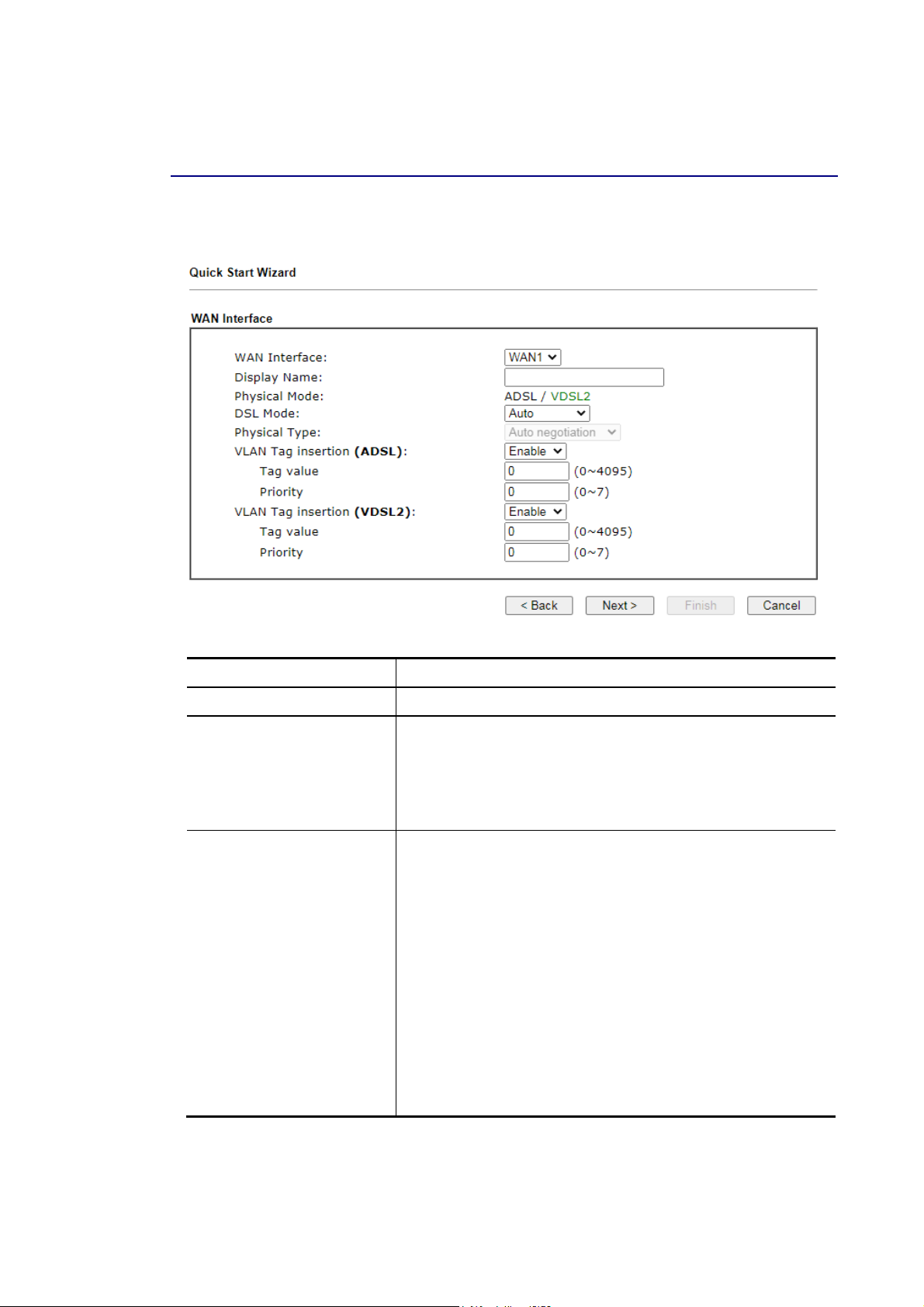
On the next screen, you can select a WAN interface to configure. The configuration steps that
follow vary slightly depending on the type of Internet connection you have.
If DSL interface is used, please choose WAN1; if Ethernet interface is used, please choose
WAN2; if 3G USB modem is used, please choose WAN3 or WAN4. Then click Next for next step.
Vigor2865 Series User’s Guide
35
Page 50
Each WAN interface will bring up different configuration page. Refer to the following for
detailed information.
II--66--11 AADDSSLL//VVDDSSLL22 CCoonnnneeccttiioonn oonn WWAANN11
This is the dedicated interface for an ADSL or VDSL2 connection.
Available settings are explained as follows:
Item Description
Display Name Optional name that identifies the connection.
DSL Mode The DSL connection mode.
Auto – The router will first attempt to connect using VDSL2,
and will fall back to ADSL if VDSL2 is unavailable.
VDSL2 only – The router will only connect using VDSL2.
ADSL only – The router will only connect using ADSL.
VLAN Tag insertion
(VDSL2)/(ADSL)
Enables or disables 802.1q VLAN tagging of W AN traffic.
Some Internet connections require the use of VLAN tags. For
more information, please contact your Internet Service
Provider.
If DSL Mode is set to Auto, separate VLAN Tag insertion
sections appear for VDSL2 and ADSL.
Enable – Enables VLAN tagging of all frames leaving the WAN
interface.
Tag value – VLAN identifier, used to tag outbound WAN
traffic. Valid tag values range from 0 to 4095.
Priority – 802.1p Class of Service, used to assign the
traffic priority. Valid priority values range from 0
(highest) to 7 (lowest).
Disable – Disables VLAN tagging.
You have to select the appropriate Internet access type according to the information from
your ISP. For example, you should select PPPoE mode if the ISP provides you PPPoE interface.
When you are have completed configuring the DSL parameters, click Next to proceed to the
following page.
36
Vigor2865 Series User’s Guide
Page 51
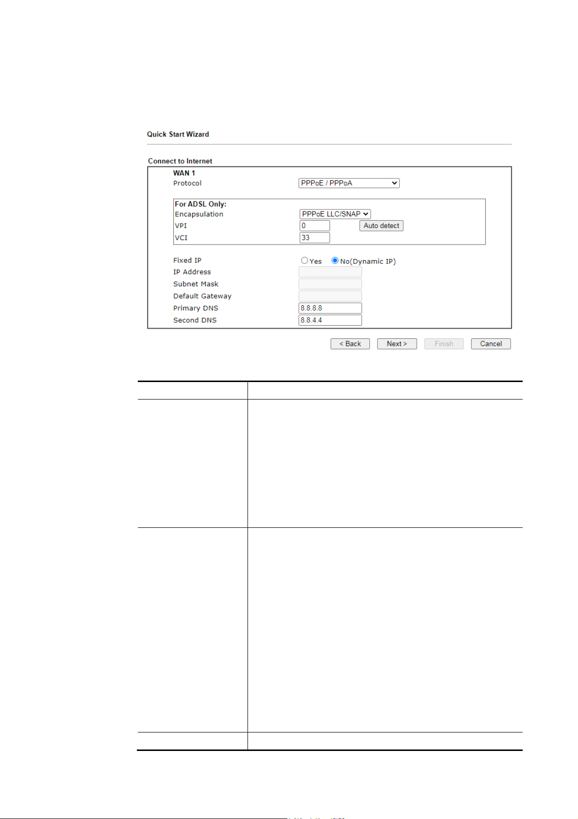
PPPPPPooEE//PPPPPPooAA
1. Choose WAN1 as WAN Interface and click the Next button; you will get the following
page.
Available settings are explained as follows:
Item Description
Protocol Connection protocol used for the DSL WAN1 connection.
PPPoE / PPPoA – Choose this if your Internet connection
mode is Point-to-Point Protocol over Ethernet, or
Point-to-Point Protocol over ATM. You will need to enter a
username and password for access authentication on the
next configuration page.
MPoA / Static or Dynamic IP – Choose this if your Internet
connection mode is Multiprotocol over ATM, Static IP or
Dynamic IP.
Choose PPPoE/PPPoA as the protocol.
For ADSL Only ADSL-specific parameters. Please contact your Internet
Service Provider for the correct values to use.
Encapsulation - Used for the ADSL connection.
PPPoE LLC/SNAP – Point-to-Point over Ethernet Logical
Link Control/Subnetwork Access Protocol
PPPoE VC MUX – Point-to-Point over Ethernet Virtual
Circuit Multiplexing
PPPoA LLC/S NAP – Point-to-Point over ATM Logical
Link Control/Subnetwork Access Protocol
PPPoA VC MUX – Point-to-Point over ATM Virtual Circuit
Multiplexing
VPI - Virtual Path Identifier.
VCI - Virtual Channel Identifier.
Auto Detect - Automatically detects and fills in the VPI and
VCI values.
Fixed IP Yes – Enables fixed IP mode
Vigor2865 Series User’s Guide
37
Page 52
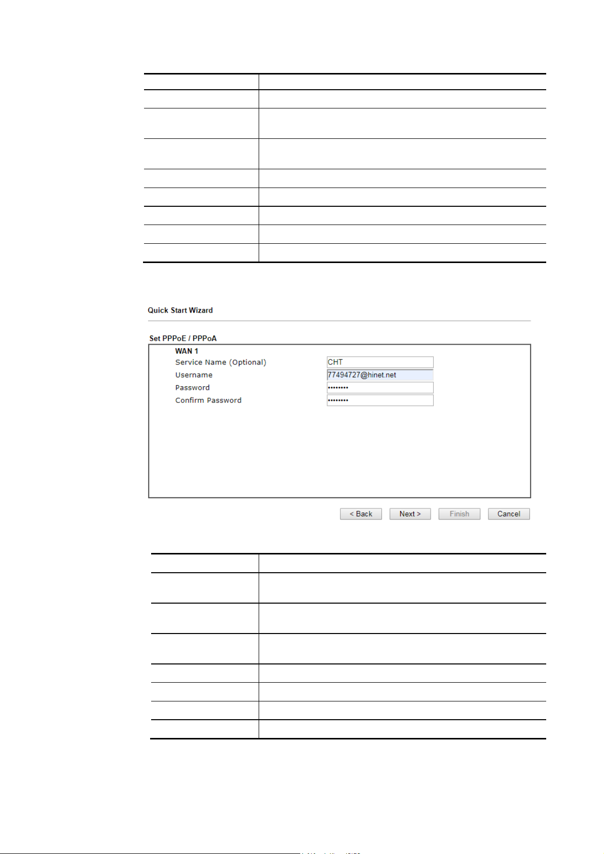
No – Disables fixed IP mode
IP Address IP address, if Fixed IP is enabled.
Subnet Mask Subnet mask of the DSL Internet connection, if Fixed IP is
enabled.
Default Gateway Default gateway of the DSL Internet connection, if Fixed IP is
enabled.
Primary DNS Primary DNS server.
Secondary DNS Secondary DNS server.
Back Click it to return to previous setting page.
Next Click it to get into the next setting page.
Cancel Click it to give up the quick start wizard.
2. After finished the above settings, simply click Next. Fill in the fields on the page using
information provided by your ISP.
38
Available settings are explained as follows:
Item Description
Service Name
(Optional)
PPP service name tag. Required by some ISPs. Leave blank
unless instructed otherwise by your ISP.
Username Username provided by the ISP for PPPoE/PPPoA
authentication. Maximum length is 63 characters.
Password Password provided by the ISP for PPPoE/PPPoA
authentication. Maximum length is 62 characters.
Confirm Password Re-enter the password for confirmation.
Back Click it to return to previous setting page.
Next Click it to get into the next setting page.
Cancel Click it to give up the quick start wizard.
Vigor2865 Series User’s Guide
Page 53
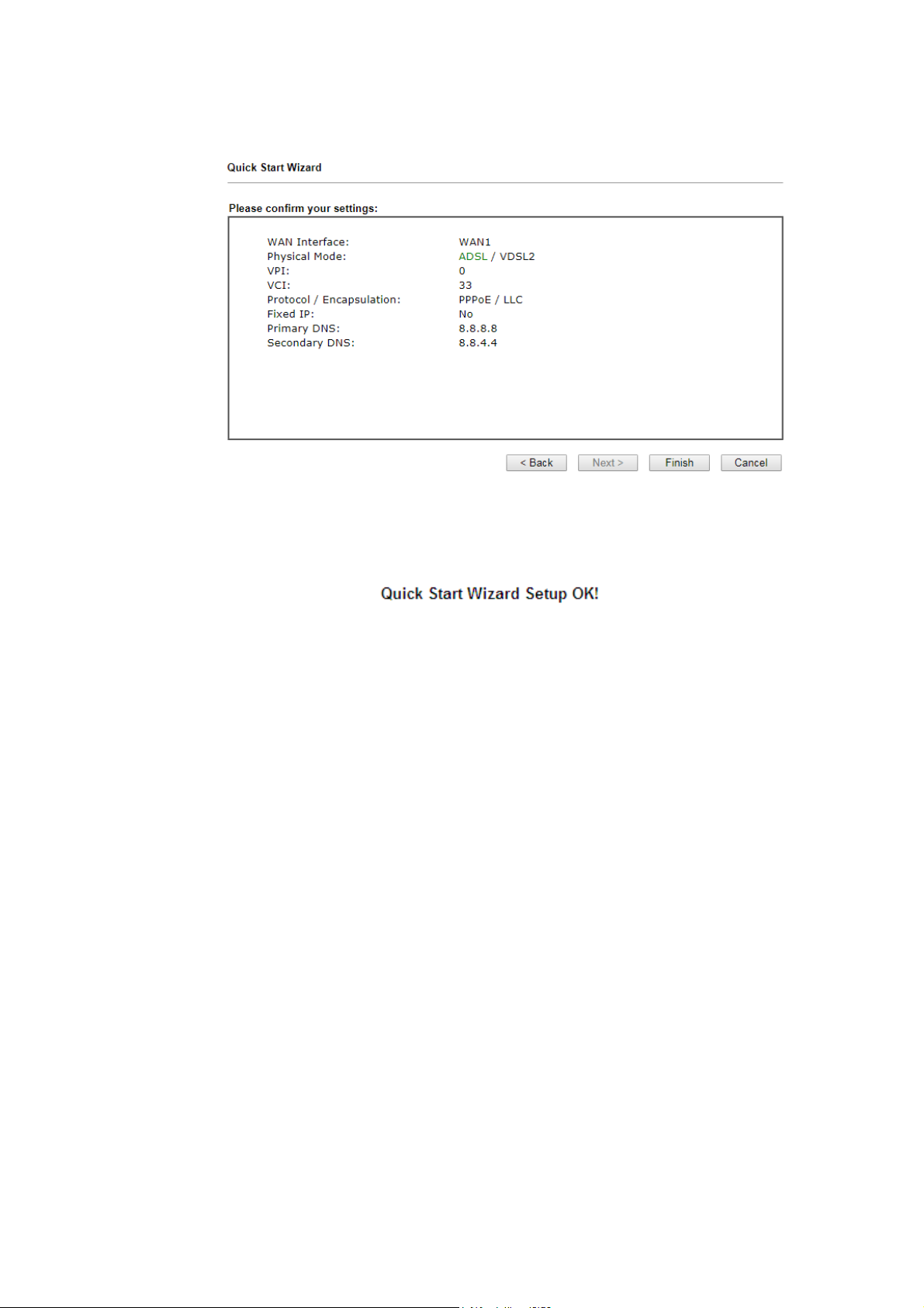
3. Fill in the fields on the page using information provided by your ISP. Then click Next for
viewing the summary of all the settings you have entered.
4. If you are satisfied with what you see, click Finish to save your changes. The following
message appears indicating that the changes have been successfully saved.
5. Now, you can enjoy surfing on the Internet.
Vigor2865 Series User’s Guide
39
Page 54
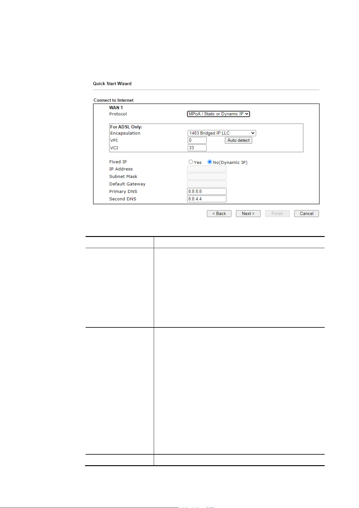
MMPPooAA // SSttaattiicc oorr DDyynnaammiicc IIPP
1. Choose WAN1 as WAN Interface and click the Next button; you will get the following
page.
Available settings are explained as follows:
Item Description
Protocol Connection protocol used for the DSL WAN1 connection.
PPPoE / PPPoA – Choose this if your Internet connection
mode is Point-to-Point Protocol over Ethernet, or
Point-to-Point Protocol over ATM. You will need to enter a
username and password for access authentication on the
next configuration page.
MPoA / Static or Dynamic IP – Choose this if your Internet
connection mode is Multiprotocol over ATM, Static IP or
Dynamic IP.
Choose MPoA / Static or Dynamic IP as the protocol.
For ADSL Only ADSL-specific parameters. Please contact your Internet
Service Provider for the correct values to use.
Encapsulation - Used for the ADSL connection.
PPPoE LLC/SNAP – Point-to-Point over Ethernet Logical
Link Control/Subnetwork Access Protocol
PPPoE VC MUX – Point-to-Point over Ethernet Virtual
Circuit Multiplexing
PPPoA LLC/S NAP – Point-to-Point over ATM Logical
Link Control/Subnetwork Access Protocol
PPPoA VC MUX – Point-to-Point over ATM Virtual Circuit
Multiplexing
VPI - Virtual Path Identifier.
VCI - Virtual Channel Identifier.
Auto Detect - Automatically detects and fills in the VPI and
VCI values.
Fixed IP Yes – Enables fixed IP mode
40
Vigor2865 Series User’s Guide
Page 55
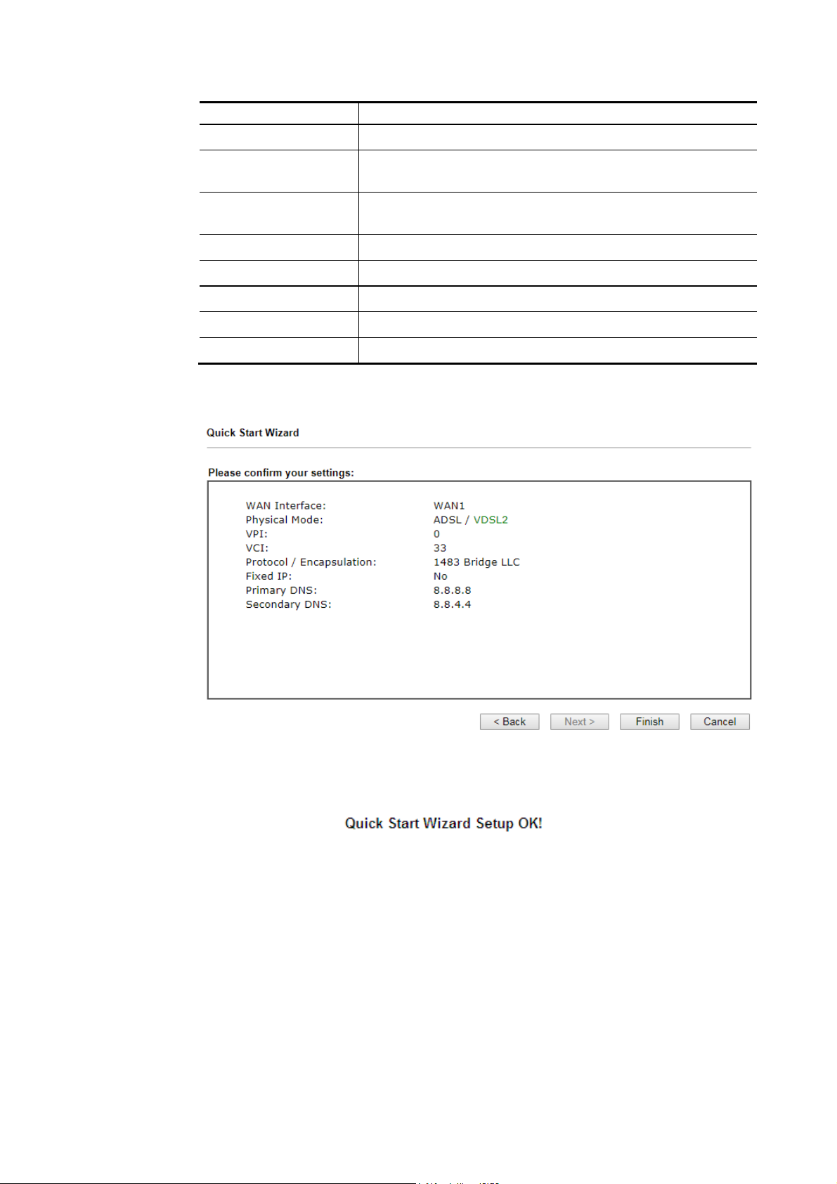
No – Disables fixed IP mode
IP Address IP address, if Fixed IP is enabled.
Subnet Mask Subnet mask of the DSL Internet connection, if Fixed IP is
enabled.
Default Gateway Default gateway of the DSL Internet connection, if Fixed IP is
enabled.
Primary DNS Primary DNS server.
Secondary DNS Secondary DNS server.
Back Click it to return to previous setting page.
Next Click it to get into the next setting page.
Cancel Click it to give up the quick start wizard.
2. Fill in the fields on the page using information provided by your ISP. Then click Next for
viewing the summary of all the settings you have entered.
3. If you are satisfied with what you see, click Finish to save your changes. The following
message appears indicating that the changes have been successfully saved.
4. Now, you can enjoy surfing on the Internet.
Vigor2865 Series User’s Guide
41
Page 56
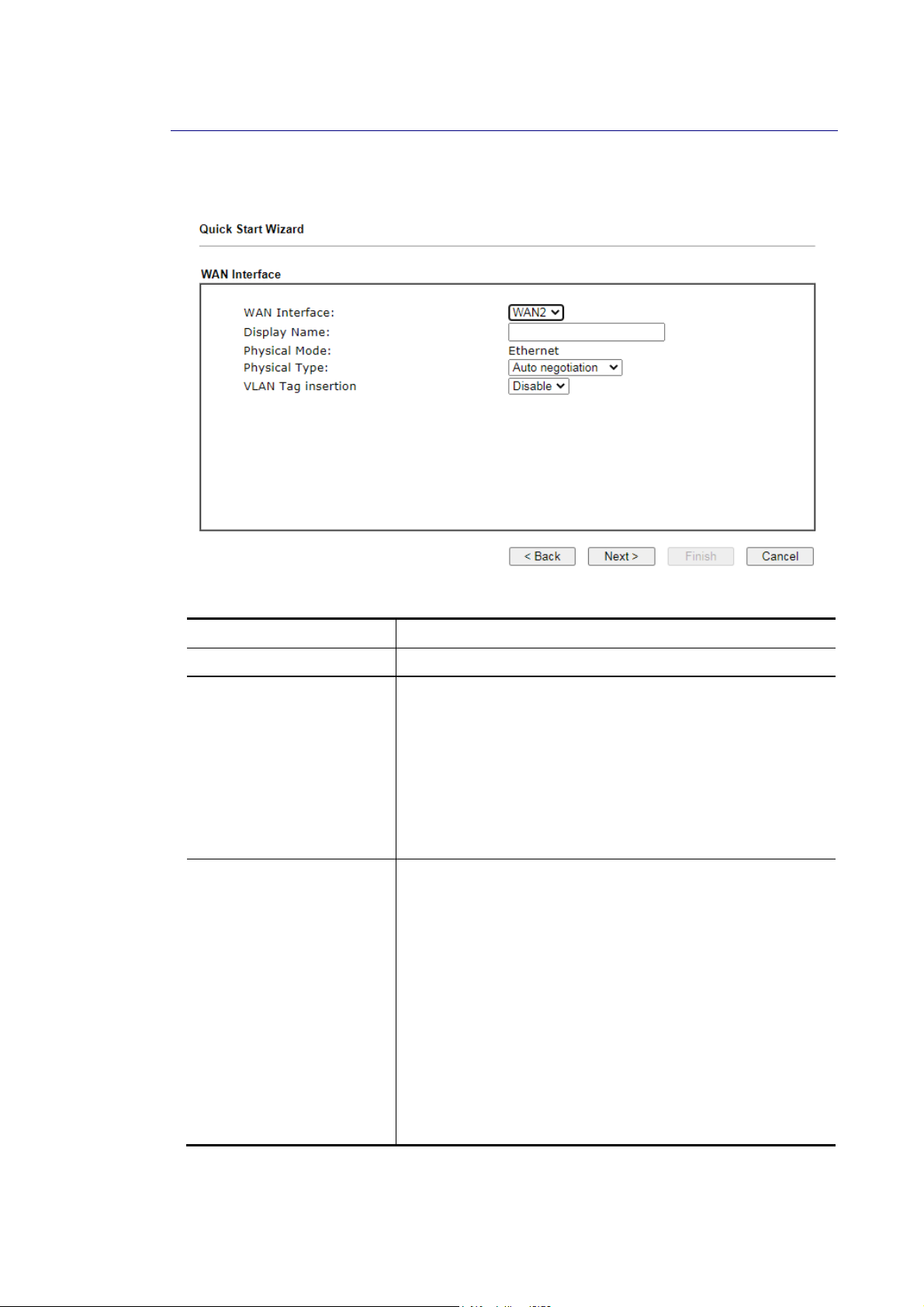
II--66--22 EEtthheerrnneett CCoonnnneeccttiioonn oonn WWAANN22
WAN2 can be configured for physical mode of Ethernet.
Available settings are explained as follows:
Item Description
Display Name Optional name that identifies the connection.
Physical Type Ethernet link parameters.
Auto negotiation – Speed and duplex mode are automatically
configured by negotiating with the connected device.
10M half duplex – 10 Mbit/s Ethernet half duplex.
10M full duplex – 10 Mbit/s Ethernet full duplex.
100M half duplex – 100 Mbit/s Fast Ethernet full duplex.
100M full duplex – 100 Mbit/s Fast Ethernet half duplex.
1000M full duplex – 1 Gbit/s Gigabit Ethernet full duplex.
VLAN Tag insertion Enables or disables 802.1q VLAN tagging of WAN traffic.
Some Internet connections require the use of VLAN tags. For
more information, please contact your Internet Service
Provider.
If DSL Mode is set to Auto, separate VLAN Tag insertion
sections appear for VDSL2 and ADSL.
Enable – Enables VLAN tagging of all frames leaving the WAN
interface.
Tag value – VLAN identifier, used to tag outbound WAN
traffic. Valid tag values range from 0 to 4095.
Priority – 802.1p Class of Service, used to assign the
traffic priority. Valid priority values range from 0
(highest) to 7 (lowest).
Disable – Disables VLAN tagging.
On the next page as shown below, please select the appropriate Internet access type
according to the information from your ISP. For example, you should select PPPoE mode if the
ISP provides you PPPoE interface. Then click Next for next step.
42
Vigor2865 Series User’s Guide
Page 57
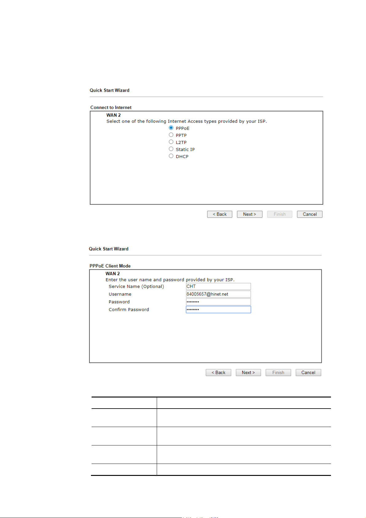
EEtthheerrnneett WWAANN22 -- PPPPPPooEE
1. Choose WAN2 as the WAN Interface and choose Ethernet as the Physical Mode. Click
the Next button. The following page will be open for you to specify Internet Access
Type.
2. Click PPPoE (Point-to-Point Protocol over Ethernet) as the Internet Access Ty pe. Then
click Next to continue.
Available settings are explained as follows:
Item Description
Service Name
(Optional)
Username Username provided by the ISP for PPPoE/PPPoA
Password Password provided by the ISP for PPPoE/PPPoA
Confirm Password Re-enter the password for confirmation.
Vigor2865 Series User’s Guide
PPP service name tag. Required by some ISPs. Leave blank
unless instructed otherwise by your ISP.
authentication. Maximum length is 63 characters.
authentication. Maximum length is 62 characters.
43
Page 58
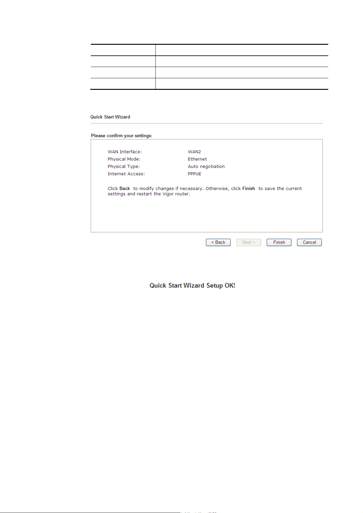
Item Description
Back Click it to return to previous setting page.
Next Click it to get into the next setting page.
Cancel Click it to give up the quick start wizard.
3. Fill in the fields on the page using information provided by your ISP. Then click Next for
viewing the summary of all the settings you have entered.
4. If you are satisfied with what you see, click Finish to save your changes. The following
message appears indicating that the changes have been successfully saved.
5. Now, you can enjoy surfing on the Internet.
44
Vigor2865 Series User’s Guide
Page 59
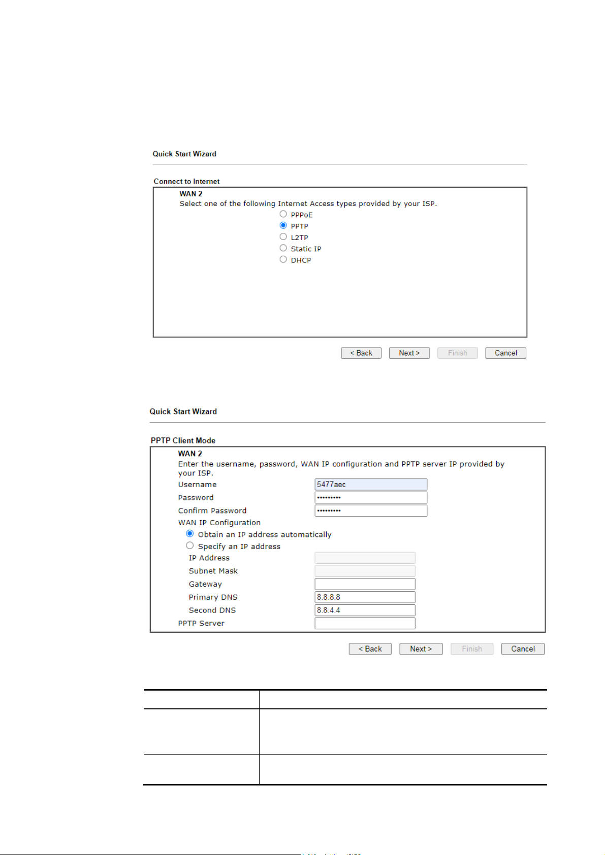
EEtthheerrnneett WWAANN22 -- PPPPTTPP//LL22TTPP
1. Choose WAN2 as the WAN Interface and choose Ethernet as the Physical Mode. Click
the Next button. The following page will be open for you to specify Internet Access
Type.
2. Click PPTP/L2TP (Point-to-Point Tunneling Protocol/ Layer 2 Tunneling Protocol) as
the Internet Access Type. Then click Next to continue.
Available settings are explained as follows:
Item Description
Username User name provided by the ISP.
The maximum length of the user name you can set is 63
characters.
Password Password provided by the ISP.
The maximum length of the password you can set is 62
Vigor2865 Series User’s Guide
45
Page 60
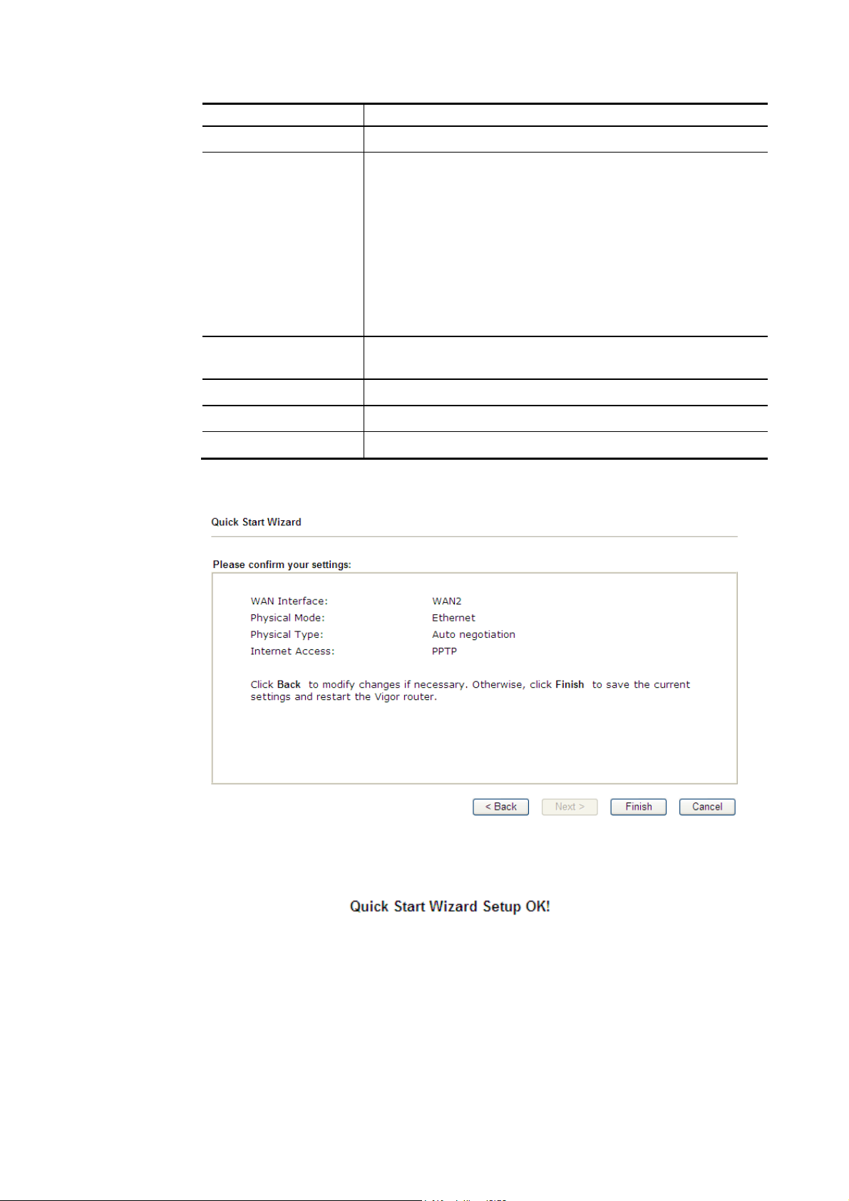
characters.
Confirm Password Re-enter the password for confirmation.
WAN IP Configuration Obtain an IP address automatically – The router receives IP
configuration information from a DHCP server.
Specify an IP address – Use the IP address, Subnet Mask and
Gateway values specified below.
IP Address - Static WAN IP address of the router.
Subnet Mask –Subnet mask of the Internet connection.
Gateway – IP address of the remote gateway.
Primary DNS – IP address of the Primary DNS server.
Second DNS – IP address of the Secondary DNS server.
PPTP Server / L2TP
IP address of the PPTP or L2TP server.
Server
Back Click it to return to previous setting page.
Next Click it to get into the next setting page.
Cancel Click it to give up the quick start wizard.
3. Fill in the fields on the page using information provided by your ISP. Then click Next for
viewing the summary of all the settings you have entered.
4. If you are satisfied with what you see, click Finish to save your changes. The following
message appears indicating that the changes have been successfully saved.
5. Now, you can enjoy surfing on the Internet.
46
Vigor2865 Series User’s Guide
Page 61
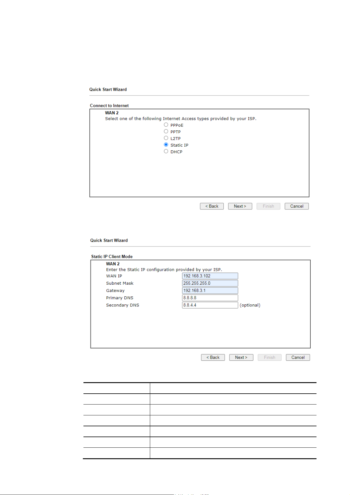
7
EEtthheerrnneett WWAANN22 -- SSttaattiicc IIPP
1. Choose WAN2 as the WAN Interface and choose Ethernet as the Physical Mode. Click
the Next button. The following page will be open for you to specify Internet Access
Type.
2. Click Static IP (Statically assigned IP address) as the Internet Access type. Simply click
Next to continue.
Available settings are explained as follows:
Item Description
WAN IP Static WAN IP address of the router.
Subnet Mask Subnet mask of the Internet connection.
Gateway IP address of the remote gateway.
Primary DNS IP address of the Primary DNS server.
Secondary DNS IP address of the Secondary DNS server.
Back Click it to return to previous setting page.
Vigor2865 Series User’s Guide
4
Page 62
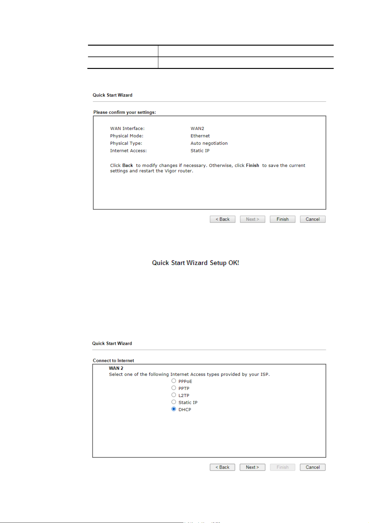
Next Click it to get into the next setting page.
Cancel Click it to give up the quick start wizard.
3. Fill in the fields on the page using information provided by your ISP. Then click Next for
viewing the summary of all the settings you have entered.
4. If you are satisfied with what you see, click Finish to save your changes. The following
message appears indicating that the changes have been successfully saved.
5. Now, you can enjoy surfing on the Internet.
EEtthheerrnneett WWAANN22 -- DDHHCCPP
1. Choose WAN2 as the WAN Interface and choose Ethernet as the Physical Mode. Click
the Next button. The following page will be open for you to specify Internet Access
Type.
48
Vigor2865 Series User’s Guide
Page 63
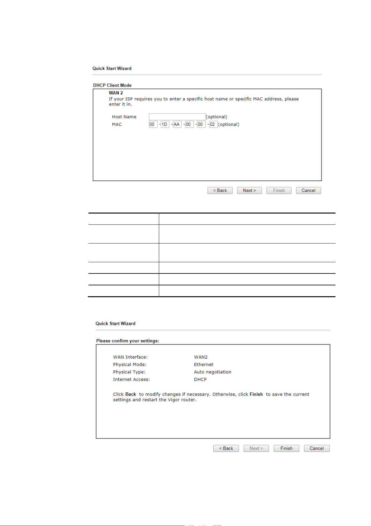
2. Click DHCP (Dynamic Host Configuration Protocol) as the Internet Access type. Simply
click Next to continue.
Available settings are explained as follows:
Item Description
Host Name Hostname required by some ISPs. Maximum length of the
host name is 39 characters.
MAC MAC address of the WAN interface. Required by some ISPs
that authenticate by MAC addresses.
Back Click it to return to previous setting page.
Next Click it to get into the next setting page.
Cancel Click it to give up the quick start wizard.
3. Fill in the fields on the page using information provided by your ISP. Then click Next for
viewing the summary of all the settings you have entered.
Vigor2865 Series User’s Guide
49
Page 64

4. If you are satisfied with what you see, click Finish to save your changes. The following
message appears indicating that the changes have been successfully saved.
5. Now, you can enjoy surfing on the Internet.
50
Vigor2865 Series User’s Guide
Page 65
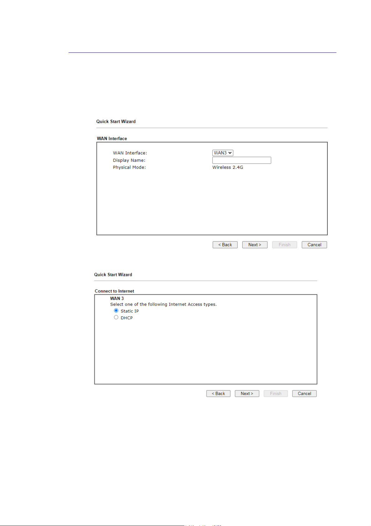
II--66--33 WWiirreelleessss 22..44GG//55GG CCoonnnneeccttiioonn oonn WWAANN33//WWAANN44
WAN3/WAN4 shall be used for wireless (2.4G or 5G) connection.
WWiirreelleessss WWAANN33//WWAANN44 -- SSttaattiicc IIPP
1. Choose WAN3/WAN4 as WAN Interface.
2. Then, click Next for getting the following page.
Vigor2865 Series User’s Guide
51
Page 66
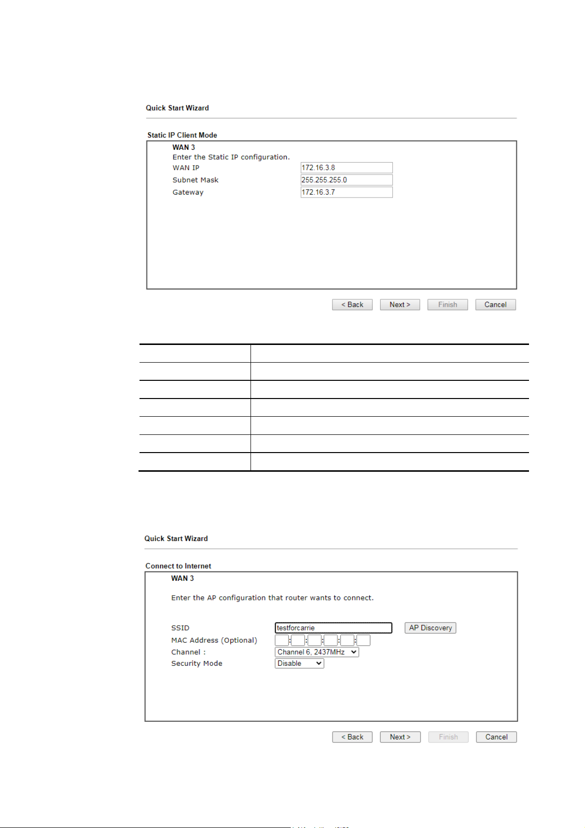
3. After click Static IP as the Internet Access type, you will get the following page. Enter
the required information and click Next to continue.
Available settings are explained as follows:
Item Description
WAN IP Static WAN IP address of the router.
Subnet Mask Subnet mask of the Internet connection.
Gateway IP address of the remote gateway.
Back Click it to return to previous setting page.
Next Click it to get into the next setting page.
Cancel Click it to give up the quick start wizard.
4. On the following page, enter the SSID of an existed AP as the wireless connection server
for this WAN. Or click AP Discovery to find an access point as the server for this WAN
interface. Click Next to continue.
52
Vigor2865 Series User’s Guide
Page 67
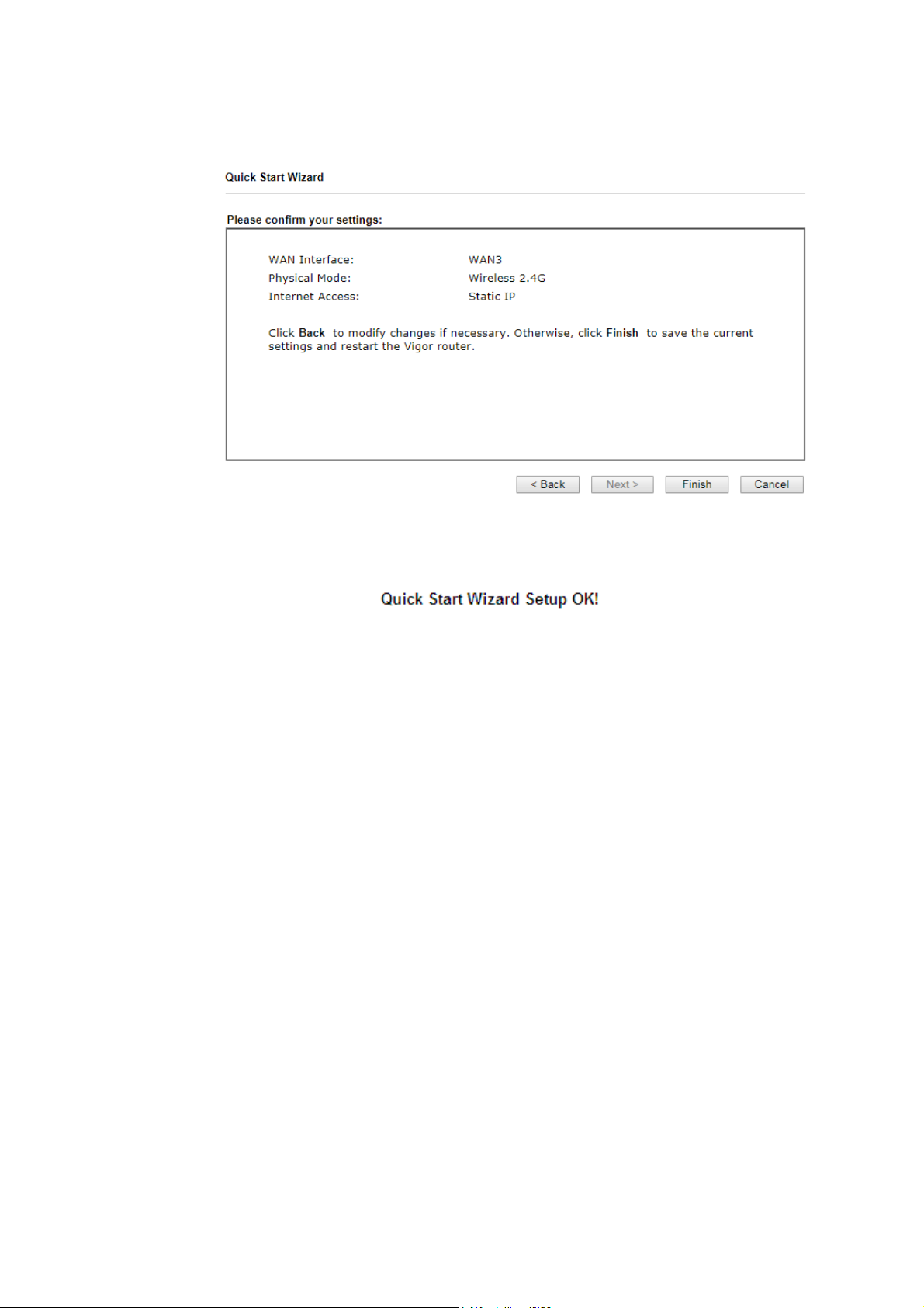
5. Fill in the fields on the page using information provided by your ISP. Then click Next for
viewing the summary of all the settings you have entered.
6. If you are satisfied with what you see, click Finish to save your changes. The following
message appears indicating that the changes have been successfully saved.
7. Now, you can enjoy surfing on the Internet.
Vigor2865 Series User’s Guide
53
Page 68
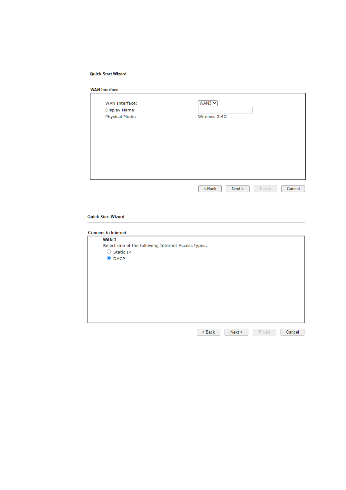
4
WWiirreelleessss WWAANN33//WWAANN44 -- DDHHCCPP
1. Choose WAN3/WAN4 as WAN Interface.
2. Then, click Next for getting the following page.
5
Vigor2865 Series User’s Guide
Page 69
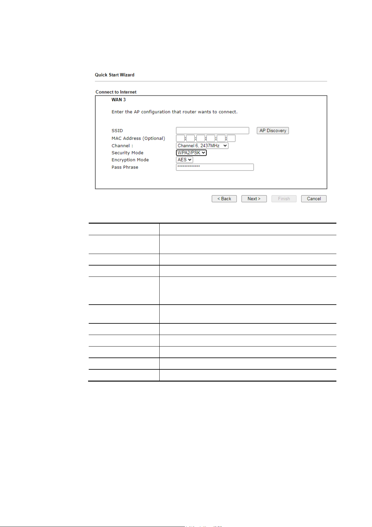
3. Select DHCP as the Internet Access type and click Next to open the following screen.
Enter the SSID of an existed AP as the wireless connection server for this WAN. Or click
AP Discovery to find an access point as the server for this WAN interface.
Available settings are explained as follows:
Item Description
SSID Enter the SSID of an existed AP. Or click AP Discovery to find
an access point as the server for this WAN interface
MAC Address Enter the MAC address of an existed AP.
Channel Select a channel of frequency of the Wireless AP.
Securithy Mode The Router connects to the wireless AP as a WEP, WPA or
WPA2 client.
Select a mode to connect to the Wireless AP.
Encryption Mode WPA/PSK uses TKIP as Encryption Mode. WPA2/PSK uses AES
as Encryption Mode.
Pass Phrase It is available when WPA/PSK or WPA2/PSK is enabled.
WEP Keys It is available when WEP is enabled.
Back Click it to return to previous setting page.
Next Click it to get into the next setting page.
Cancel Click it to give up the quick start wizard.
Vigor2865 Series User’s Guide
55
Page 70
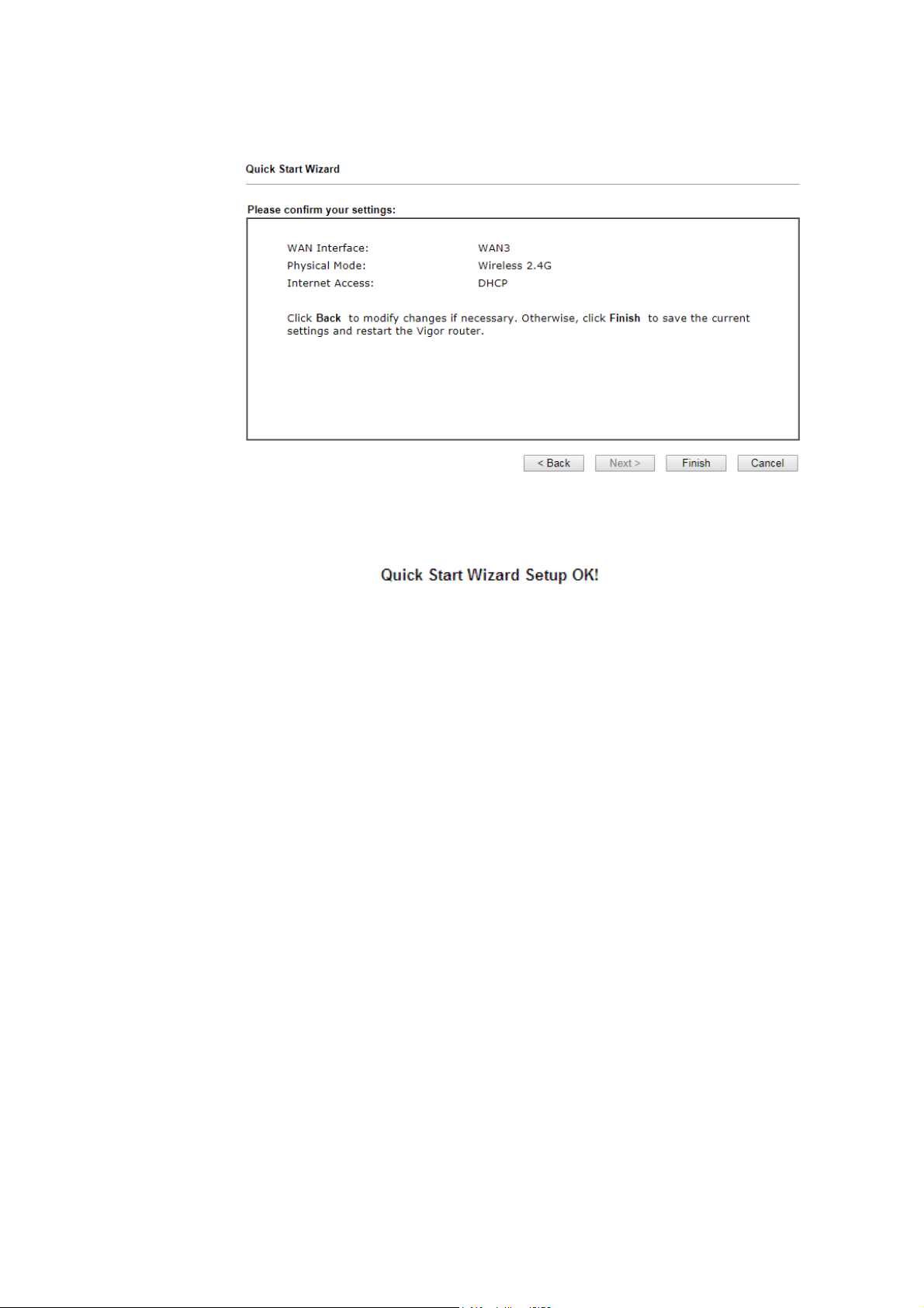
4. Fill in the fields on the page using information provided by your ISP. Then click Next for
viewing the summary of all the settings you have entered.
5. If you are satisfied with what you see, click Finish to save your changes. The following
message appears indicating that the changes have been successfully saved.
6. Now, you can enjoy surfing on the Internet.
56
Vigor2865 Series User’s Guide
Page 71
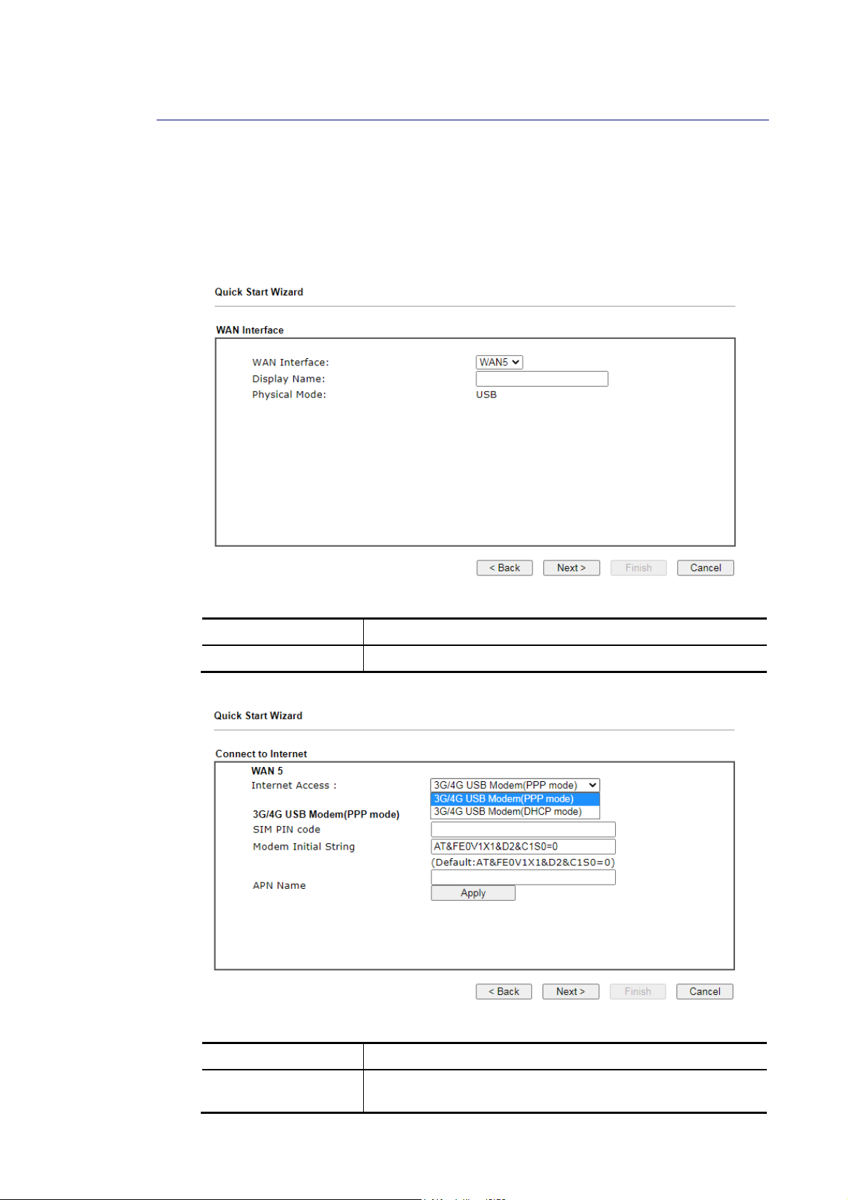
7
II--66--44 UUSSBB CCoonnnneeccttiioonn oonn WWAANN55//WWAANN66
If you will be using a 3G or 4G USB modem to connect to the Internet, you will first need to
connect the modem to one of the USB ports before proceeding with the following steps.
Select WAN5 from the WAN Interface dropdown list if the modem is plugged into USB 1. Select
WAN6 if the modem is plugged into the USB 2.
1. Choose WAN5/WAN6 as WAN Interface.
Available settings are explained as follows:
Item Description
Display Name Optional name that identifies the connection.
2. Then, click Next for getting the following page.
Available settings are explained as follows:
Item Description
Internet Access 3G/4G USB Modem(PPP mode) – Point-to-Point Protocol is
used to establish a connection.
Vigor2865 Series User’s Guide
5
Page 72
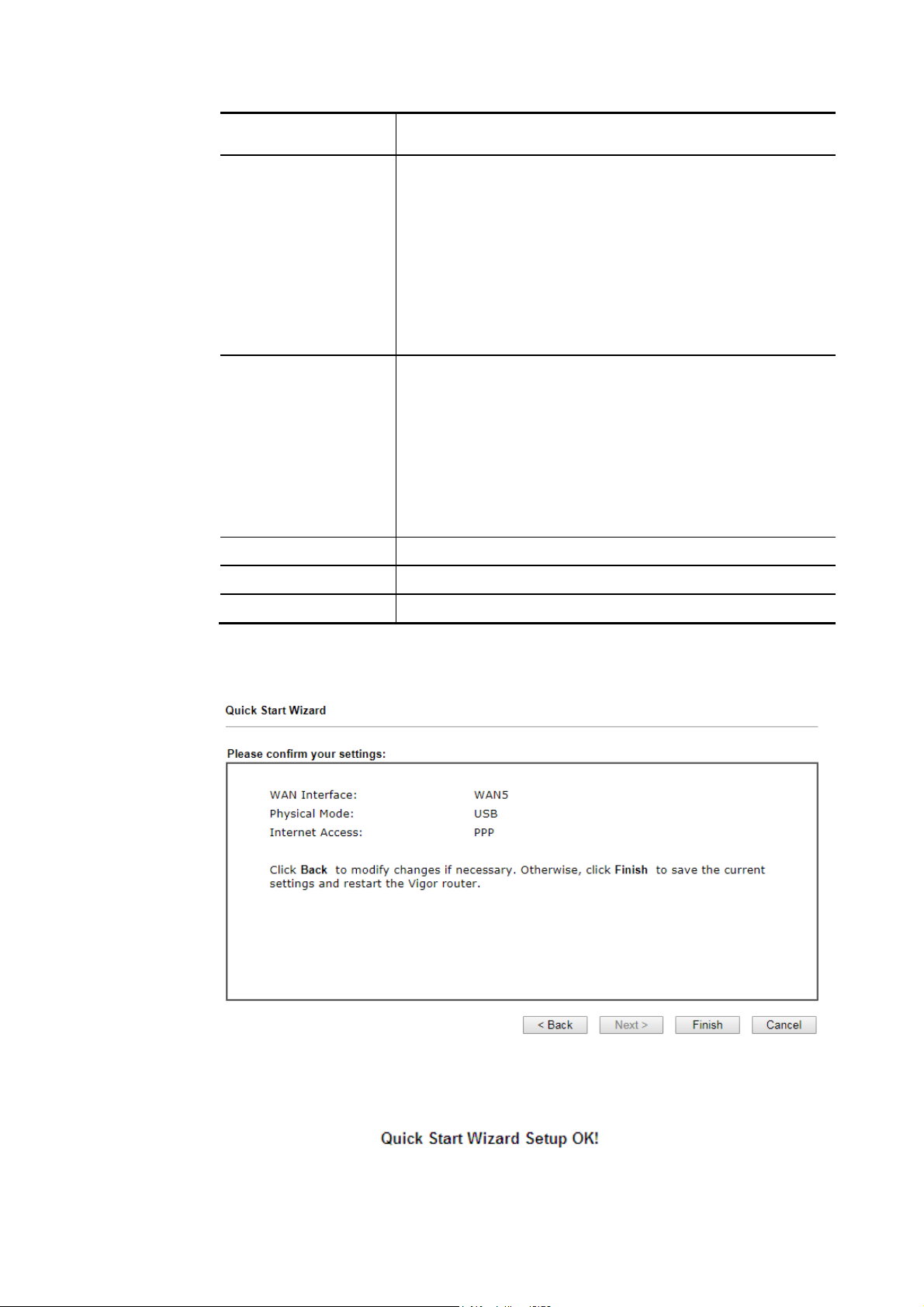
4G USB Modem(DHCP mode) – Dynamic Host Configuration
Protocol is used to establish a connection.
3G/4G USB Modem
(PPP mode)
SIM Pin code – PIN code of the SIM card in the modem. The
maximum length of the PIN is 15 characters.
Modem Initial String – String to be sent to the modem during
initialization. The default value should suffice in most cases.
If you need assistance with setting this value, please contact
your ISP or carrier. The maximum length of the string is 47
characters.
APN Name – Access Point Name to be used for the
connection. Please contact your ISP or carrier for the
appropriate value. Enter the name and click Apply.
3G/4G USB Modem
(DHCP mode)
SIM Pin code – PIN code of the SIM card in the modem. The
maximum length of the PIN is 15 characters.
Network Mode – Force Vigor router to connect Internet with
the mode specified here. If you choose 4G/3G/2G as network
mode, the router will choose a suitable one according to the
actual wireless signal automatically.
APN Name – Access Point Name to be used for the
connection. Please contact your ISP or carrier for the
appropriate value. Enter the name and click Apply.
Back Click it to return to previous setting page.
Next Click it to get into the next setting page.
Cancel Click it to give up the quick start wizard.
3. Fill in the fields on the page using information provided by your ISP. Then click Next for
viewing the summary of all the settings you have entered.
4. If you are satisfied with what you see, click Finish to save your changes. The following
message appears indicating that the changes have been successfully saved.
5. Now, you can enjoy surfing on the Internet.
58
Vigor2865 Series User’s Guide
Page 73
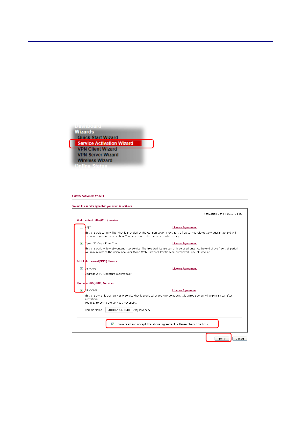
II--77 SSeerrvviiccee AAccttiivvaattiioonn WWiizzaarrdd
The Service Activation Wizard guides you through the activation of the Web Content Filter
(WCF) and Application Enforcement (APPE) free trial subscriptions. For detailed information
on the WCF and APPE services, please see the sections Web Content Filter Profile and APP
Enforcement Profile.
Note: You must log in as the administrator (admin m ode) to use the Service Activation Wizard.
1. Open Wizards>>Service Activation Wizard.
2. The screen of Service Activation Wizard will be shown as follows. You can activate the
Web content filter services and/or APPE enforcement service and / or DDNS service at
the same time or individually. When you finish the selection, please click Next.
BPjM is web content filter (WCF) for German Speaking users. It is
ideal for your family to provide more Internet security for
youngsters.
Cryan 30-day trial is WCF which offers 30-day trial period.
Vigor2865 Series User’s Guide
59
Page 74
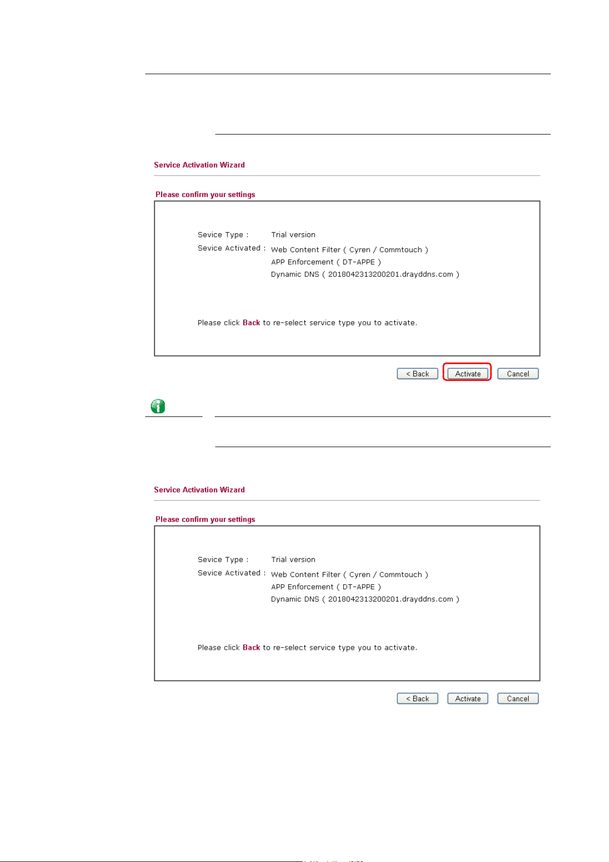
DT-APPE, developed by DrayTek, offers a mechanism to upgrade
APPE signature automatically.
DT-DDNS, developed by DrayTek, offers one year free charge
service of dynamic DNS service for internal use.
3. A confirmation page detailing your selection will be displayed. Please click Activate.
Info
The service will be activated and applied as the default rule configured
in Firewall>>General Setup.
4. Now, the web page will display the service that you have activated according to your
selection(s).
60
Vigor2865 Series User’s Guide
Page 75
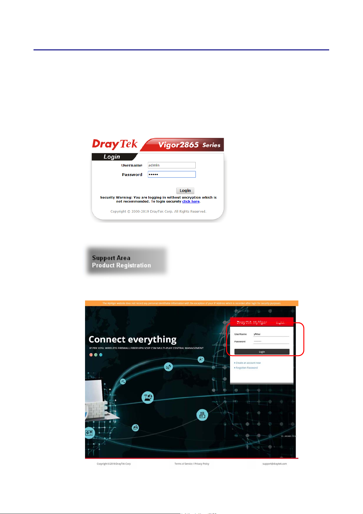
II--88 RReeggiisstteerriinngg VViiggoorr RRoouutteerr
You have finished the configuration of Quick Start Wizard and you can surf the Internet at any
time. Now it is the time to register your Vigor router to MyVigor website for getting more
service. Please follow the steps below to finish the router registration.
1 Please login the web configuration interface of Vigor router by typing “admin/admin” as
User Name / Password.
2 Click Support Area>>Production Registration from the home page.
3 A Login page will be shown on the screen. Please Enter the account and password that
you created previously. And click Login.
Vigor2865 Series User’s Guide
61
Page 76
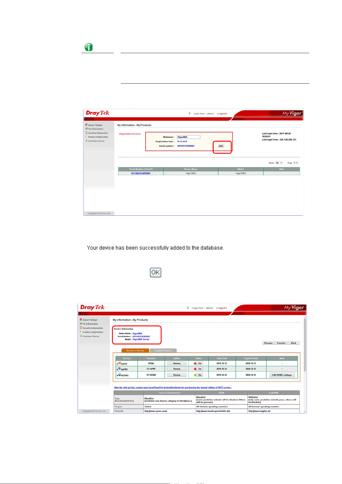
Info
If you haven’t an accessing account, please refer to section Creating an
Account for MyVigor to create your own one. Please read the articles
on the Agreement regarding user rights carefully while creating a user
account.
4 The following page will be displayed after you logging in MyVigor. Type a nickname for
the router, then click Add.
5 When the following page appears, your router information has been added to the
database.
6 After clicking OK, you will see the following page. Your router has been registered to
myvigor website successfully.
62
Vigor2865 Series User’s Guide
Page 77

P
arrtt IIII
P
a
C
o
n
n
C
o
n
eccttiivviittyy
n
e
It means wide area network. Public IP will be
used in WAN.
It means local area network. Private IP will be
used in LAN. Local Area Network (LAN) is a group
of subnets regulated and ruled by router. The
design of network structure is related to what
type of public IP addresses coming from your ISP.
When the data flow passing through, the Network
Address Translation (NAT) function of the router
will dedicate to translate public/private
addresses, and the packets will be delivered to
the correct host PC in the local area network.
DNS, LAN DNS, IGMP, LDAP, UpnP, IGMP, WOL,
RADIUS, SMS, Bonjour
Static Route, Load-Balance/Route Policy
Vigor2865 Series User’s Guide
63
Page 78

4
IIII--11 WWAANN
It allows users to access Internet.
BBaassiiccss ooff IInntteerrnneett PPrroottooccooll ((IIPP)) NNeettwwoorrkk
IP means Internet Protocol. Every device in an IP-based Network including routers, print
server, and host PCs, needs an IP address to identify its location on the network. To avoid
address conflicts, IP addresses are publicly registered with the Network Information Centre
(NIC). Having a unique IP address is mandatory for those devices participated in the public
network but not in the private TCP/IP local area networks (LANs), such as host PCs under the
management of a router since they do not need to be accessed by the public. Hence, the NIC
has reserved certain addresses that will never be registered publicly. These are known as
private IP addresses, and are listed in the following ranges:
WWhhaatt aarree PPuubblliicc IIPP AAddddrreessss aanndd PPrriivvaattee IIPP AAddddrreessss
As the router plays a role to manage and further protect its LAN, it interconnects groups of
host PCs. Each of them has a private IP address assigned by the built-in DHCP server of the
Vigor router. The router itself will also use the default private IP address: 192.168.1.1 to
communicate with the local hosts. Meanwhile, Vigor router will communicate with other
network devices through a public IP address. When the data flow passing through, the
Network Address Translation (NAT) function of the router will dedicate to translate
public/private addresses, and the packets will be delivered to the correct host PC in the local
area network. Thus, all the host PCs can share a common Internet connection.
From 10.0.0.0 to 10.255.255.255
From 172.16.0.0 to 172.31.255.255
From 192.168.0.0 to 192.168.255.255
GGeett YYoouurr PPuubblliicc IIPP AAddddrreessss ffrroomm IISSPP
In ADSL deployment, the PPP (Point to Point)-style authentication and authorization is
required for bridging customer premises equipment (CPE). Point to Point Protocol over
Ethernet (PPPoE) connects a network of hosts via an access device to a remote access
concentrator or aggregation concentrator. This implementation provides users with
significant ease of use. Meanwhile it provides access control, billing, and type of service
according to user requirement.
When a router begins to connect to your ISP, a serial of discovery process will occur to ask for
a connection. Then a session will be created. Your user ID and password is authenticated via
PAP or CHAP with RADIUS authentication system. And your IP address, DNS server, and other
related information will usually be assigned by your ISP.
NNeettwwoorrkk CCoonnnneeccttiioonn bbyy 33GG//44GG UUSSBB MMooddeemm
For 3G/4G mobile communication through Access Point is popular more and more, Vigor2865
adds the function of 3G/4G network connection for such purpose. By connecting 3G/4G USB
Modem to the USB port of Vigor2865, it can support LTE/HSDPA/UMTS/EDGE/ GPRS/GSM and
the future 3G/4G standard (HSUPA, etc). Vigor2865n with 3G/4G USB Modem allows you to
receive 3G/4G signals at any place such as your car or certain location holding outdoor
activity and share the bandwidth for using by more people. Users can use LAN ports on the
router to access Internet. Also, they can access Internet via 802.11(a/b/g/n/ac) wireless
standard, and enjoy the powerful firewall, bandwidth management, and VPN features of
Vigor2865n series.
6
Vigor2865 Series User’s Guide
Page 79
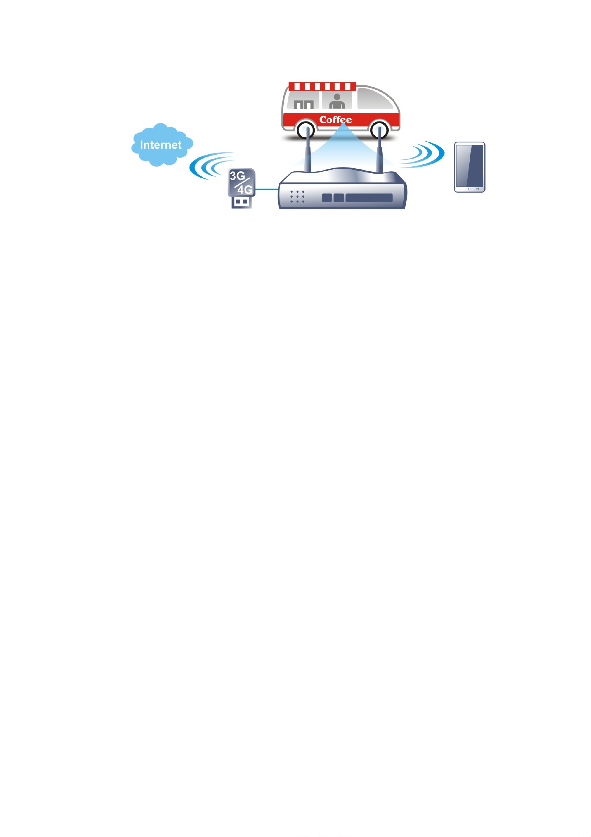
After connecting into the router, 3G/4G USB Modem will be regarded as the WAN3/WAN4 port.
However, the original WAN1 and WAN2 still can be used and Load-Balance can be done in the
router. Besides, 3G/4G USB Modem in WAN3/WAN4 also can be used as backu p device.
Therefore, when WAN1 and WAN2 are not available, the router will use 3.5G for supporting
automatically. The supported 3G/4G USB Modem will be listed on DrayTek web site. Please
visit www.draytek.com for more detailed information.
Vigor2865 Series User’s Guide
65
Page 80
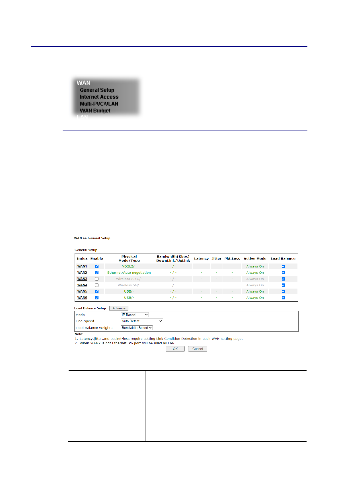
WWeebb UUsseerr IInntteerrffaaccee
IIII--11--11 GGeenneerraall SSeettuupp
This section will introduce some general settings of Internet and explain the connection
modes for WAN1, WAN2, WAN3, WAN4, WAN5 and WAN6 in details.
This router supports multiple-WAN function. It allows users to access Internet and combine
the bandwidth of the multiple WANs to speed up the transmission through the network. Each
WAN port can connect to different ISPs, even if the ISPs use different technology to provide
telecommunication service (such as DSL, Cable modem, etc.). If any connection problem
occurred on one of the ISP connections, all the traffic will be guided and switched to the
normal communication port for proper operation. Please configure WAN1, WAN2, WAN3,
WAN4, WAN5 and WAN6 settings.
This webpage allows you to set general setup for WAN1, WAN2, WAN3, WAN4, WAN5 and
WAN6 respectively.
Available settings are explained as follows:
Item Description
Index Click on the WAN# link to bring up its settings page.
WAN1: ADSL/VDSL WAN interface.
WAN2: Selectable Ethernet WAN interface.
WAN3: Wireless 2.4G Wi-Fi WAN interface.
WAN4: Wireless 5G Wi-Fi WAN interface.
WAN5: 3G/4G USB modem connected to USB1.
WAN6: 3G/4G USB modem connected to USB2.
66
Vigor2865 Series User’s Guide
Page 81
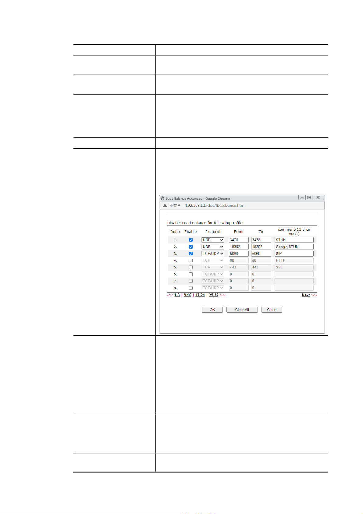
7
Enable Select to enable WAN interface.
Physical Mode / Type Display the physical mode and physical type of such WAN
interface.
Bandwidth(Kbps)
DownLink/UpLink
Display the downstream and upstream rate of such WAN
interface.
Active Mode Display whether such WAN interface is Active device or
backup device.
Always On - WAN is always enabled.
Backup (WAN#) - Display the backup WAN interface for such
WAN when it is disabled.
Load Balance Select to enable the load balance function.
Load Balance Setup Advance - Load Balance for the traffic of STUN, google
STUN, and SIP are disabled in default to prevent from
conflict. The following dialog allows you to define protocol,
port and name for the traffic not to be applied with load
balance. That is, when an item is enabled (checked), it might
not be affected by load balance.
Mode IP Based - The same source / destination IP pair will select
the same WAN interface as policy. It is the default setting.
Session Based- All of the WAN interfaces will be used (as
out-going WAN) for passing through new sessions to get
better transmission speed. Though good speed test result for
throughput might be reached; however, some web site may
not open smoothly, especially the site need authentication,
e.g., FTP.
If you have no strong demand about speed test result, keep
default settings as IP based.
Line Speed This option is available for multiple-WAN for getting enough
bandwidth for each WAN port. If you know the practical
bandwidth for your WAN interface, please choose the setting
of According to Line Speed. Otherwise, please choose Auto
Detect to let the router reach the best load balance.
Load Balance Weights There are four weight types for choosing to meet your
request.
Vigor2865 Series User’s Guide
6
Page 82
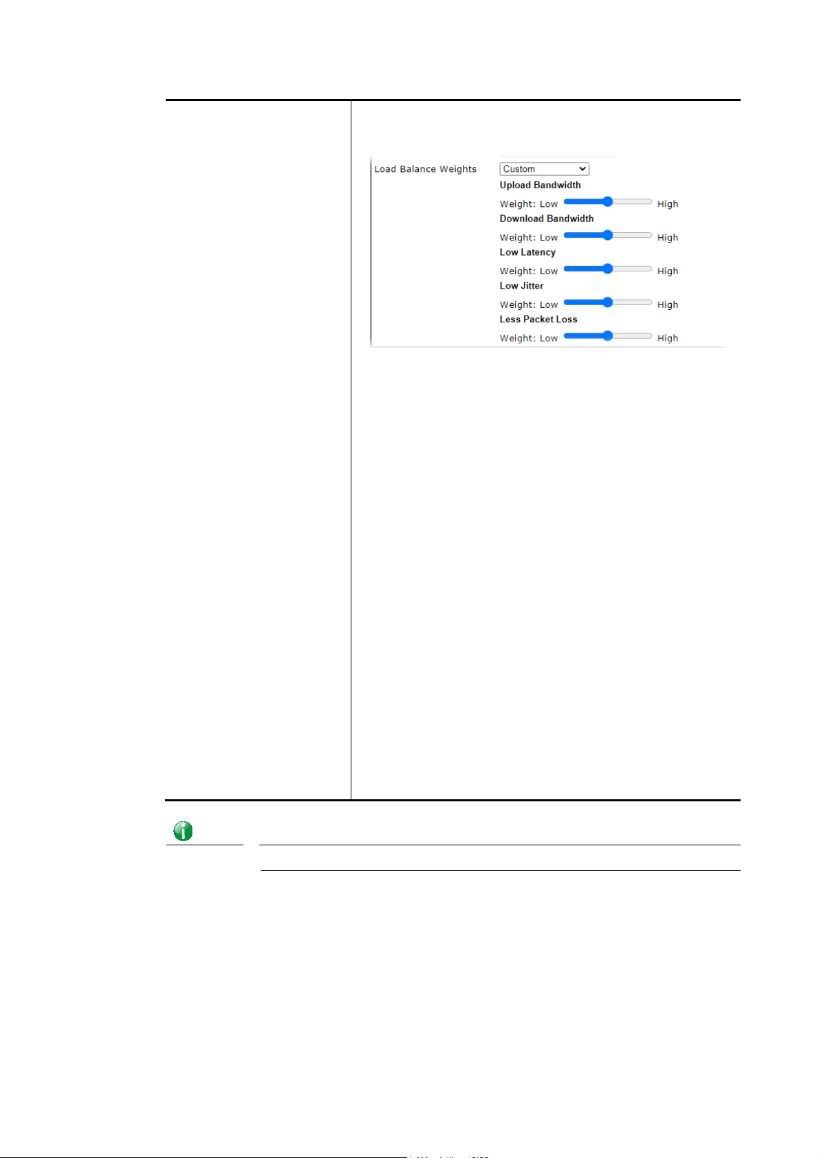
Info
Custom - You can distribute the usage ratio for each WAN
interface by setting weights for bandwidth, latency, jitter,
and packet loss respectively.
Upload / Download Bandwidth - The higher the weight
is, the WAN interface with higher bandwidth will get
higher usage.
Low Latency - It defines the time taken by Vigor router
when sending the packets to the IP set in Link Condition
Detection. The higher the weight is, the WAN interface
with lower latency will get higher usage.
Low Jitter - It defines the change rate of latency. For
stable session, small jitter value will be better. The
higher the weight is, the WAN interface with lower
jitter will get higher usage.
Less Packet Loss - It defines the proportion that
packets will be discarded before arriving at the IP set in
Link Condition Detection. The higher the weight is, the
WAN interface with lower packet loss will get higher
usage.
Bandwidth-Based - The load balance weight for each WAN
will be executed according to line speed setting
(DownLink/UpLink Rate). This is default setting.
Quality-Based - The load balance weight for each WAN will
be executed according to the transmission rate, latency time
and the jitter time.
Reliabiltiy-Based - The load balance weight for each WAN
will be executed according to line speed and packet loss
value. Usually, the WAN interface with low packet loss will
have the higher ratio to be used.
Wired router (e.g., Vigor2865) does not support WAN3 and WAN4.
After finished the above settings, click OK to save the settings.
68
Vigor2865 Series User’s Guide
Page 83
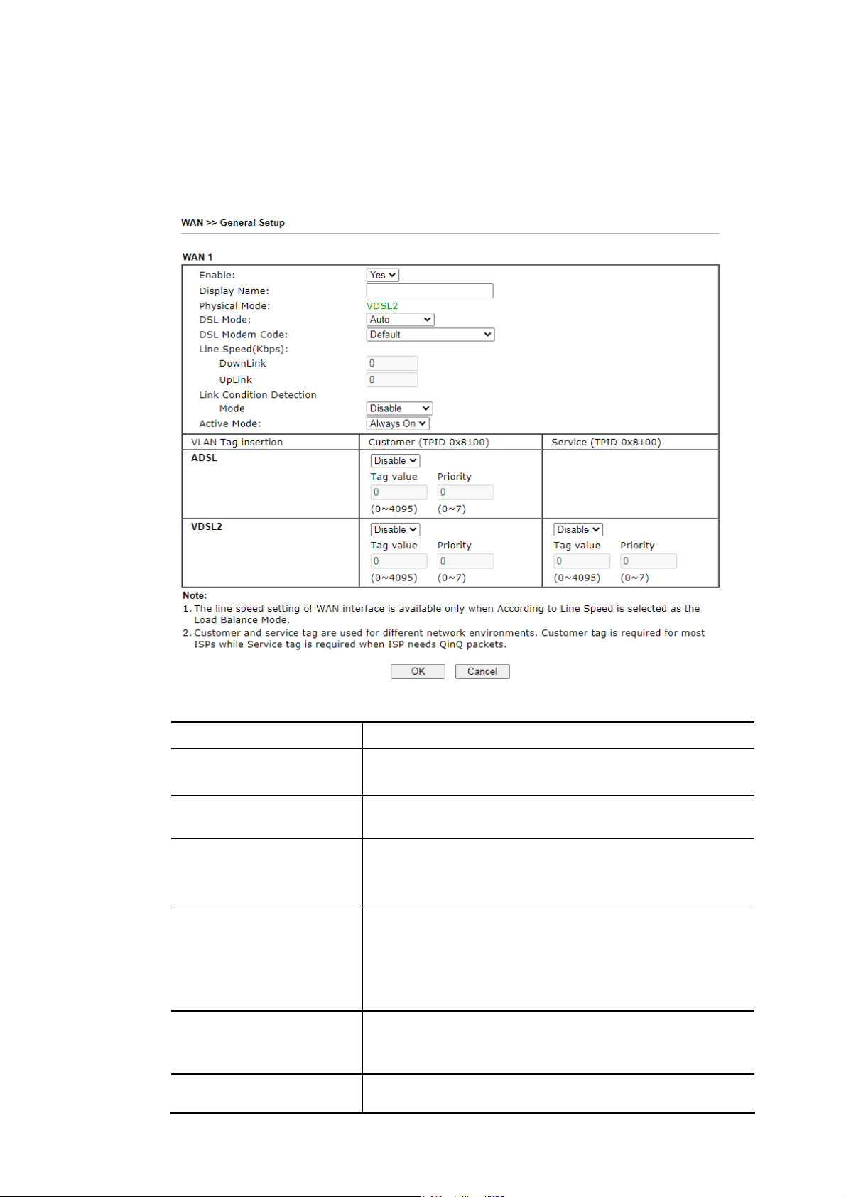
)
IIII--11--11--11 WWAANN11((AADDSSLL//VVDDSSLL22)
Vigor router will detect the physical line is connected by ADSL or VDSL2 automatically.
Therefore, this page allows you to configure settings for ADSL and VDSL2 at one time. That is,
it is not necessary for you to configure different profile settings for ADSL and VDSL2
respectively.
Available settings are explained as follows:
Item Description
Enable Yes - WAN is enabled.
No - WAN is disabled.
Display Name Optional name to identify the WAN. Enter the description
for the interface.
Physical Mode DSL connection mode in use.
VDSL2 - Current DSL mode is VDSL2.
ADSL - Current DSL mode is ADSL.
DSL Mode DSL connection modes the modem is allowed to use.
Auto - Router automatically selects the best available
connection mode.
VDSL2 only - Router only connects in VDSL2 mode.
ADSL - Router only connects in ADSL mode.
DSL Modem Code DSL firmware code to be used.
Choose Default unless you have been instructed to use
other values by technical support.
Line Speed (Kpbs) It determines the ratio of outbound connections made by
the router across all active WANs. The Line Speed on
Vigor2865 Series User’s Guide
69
Page 84

WAN>>General Setup must first be set to According to
Line Speed before these values can be changed.
DownLink - WAN downlink speed.
UpLink - WAN uplink speed.
Link Condition Detection In order for the system to detect the latency, jitter, and
packet-loss status for each WAN interface, you have to
specify the IP transmitting data through the interface.
Mode - Choose Ping Detect, Http Detect, or Disable as
detection mode. If Ping Detect or Http Detect is selected,
you have to configure the following option.
Primary Ping IP - Enter an IP address.
Secondary Ping IP - Enter an IP address.
Ping Interval - Set a time interval (unit:second) for the
system to ping the IP address specified above.
Active Mode Always On - WAN is always enabled.
Backup – WAN is enabled only when other WAN ports
specified in Backup For (see below), have lost connection.
Backup For - Select the WANs for which this WAN is
intended to serve as a backup.
Active When - Set the condition for backup
connection.
- Any – The selected WAN(s) will be activated
when any master WAN interface disconnects.
- All – All of the backup WANs will be activated
only when all master WAN interface
disconnects.
- Fails to connect – When the active WAN failed,
the WAN selected above will be activated as the
main network connection.
- Meet All/Any of the following conditions –
When the upload traffic, download traffic,
latency, jitter and/or packet loss of active WAN
reaches the traffic threshold (specified here),
the backup WAN will be enabled automatically
to share the overloaded data traffic.
70
VLAN Tag insertion
(ADSL/VDSL2)
Determines whether 802.1ad VLAN tags will be added to
outbound WAN traffic in ADSL/VDSL 2 mode. Check with
your ISP to determine if this is required, and if so, the
proper tag and priority values to be used.
Enabled - Tagging enabled.
Disabled - Tagging disabled.
Tag value – Value must be between 1 and 4095.
Priority – Priority code point (PCP). Value must be between
0 and 7.
After finished the above settings, click OK to save the settings.
Vigor2865 Series User’s Guide
Page 85
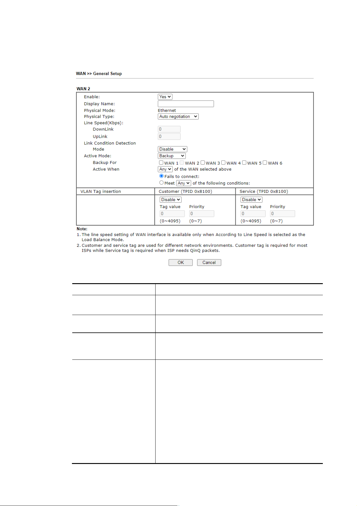
IIII--11--11--22 WWAANN22 ((EEtthheerrnneett))
WAN2 can be configured for physical mode of Ethernet.
Available settings are explained as follows:
Item Description
Enable Yes - WAN is enabled.
No - WAN is disabled.
Display Name Optional name to identify the WAN. Enter the description
for the interface.
Physical Mode Physical connection used for this WAN.
Ethernet - WAN connection to be established through the
WAN2 Ethernet port.
Physical Type (Available only when Physical Mode is set to Ethernet)
Auto negotiation- Ethernet connection speed is
automatically negotiation between the router and the ISP’s
equipment.
10M half duplex-Ethernet speed is manually set to 10
Mbit/s, half duplex.
10M full duplex- Ethernet speed is manually set to 10
Mbit/s, full duplex.
100M half duplex- Ethernet speed is manually set to 100
Mbit/s, half duplex.
100M full duplex- Ethernet speed is manually set to 100
Mbit/s, full duplex.
1000M full duplex- Ethernet speed is manually set to 1
Vigor2865 Series User’s Guide
71
Page 86

Gbit/s, full duplex.
Line Speed (Kbps) It determines the ratio of outbound connections made by
the router across all active WANs. The Line Speed on
WAN>>General Setup must first be set to According to
Line Speed before these values can be changed.
DownLink - WAN downlink speed.
UpLink - WAN uplink speed.
Link Condition Detection In order for the system to detect the latency, jitter, and
packet-loss status for each WAN interface, you have to
specify the IP transmitting data through the interface.
Mode - Choose Ping Detect, Http Detect, or Disable as
detection mode. If Ping Detect or Http Detect is selected,
you have to configure the following option.
Primary Ping IP - Enter an IP address.
Secondary Ping IP - Enter an IP address.
Ping Interval - Set a time interval (unit:second) for the
system to ping the IP address specified above.
Active Mode Always On - WAN is always enabled.
Backup – WAN is enabled only when other WAN ports
specified in Backup For (see below), have lost connection.
Backup For - Select the WANs for which this WAN is
intended to serve as a backup.
Active When - Set the condition for backup
connection.
- Any – The selected WAN(s) will be activated
when any master WAN interface disconnects.
- All – All of the backup WANs will be activated
only when all master WAN interface disconnects.
- Fails to connect – When the active WAN failed,
the WAN selected above will be activated as the
main network connection.
- Meet All/Any of the following conditions –
When the upload traffic, download traffic,
latency, jitter and/or packet loss of active WAN
reaches the traffic threshold (specified here),
the backup WAN will be enabled automatically
to share the overloaded data traffic.
VLAN Tag insertion Determines whether 802.1ad VLAN tags will be added to
outbound WAN traffic in ADSL/VDSL 2 mode. Check with
your ISP to determine if this is required, and if so, the
proper tag and priority values to be used.
Enabled - Tagging enabled.
Disabled - Tagging disabled.
Tag value – Value must be between 1 and 4095.
Priority – Priority code point (PCP). Value must be between
0 and 7.
After finished the above settings, click OK to save the settings.
72
Vigor2865 Series User’s Guide
Page 87
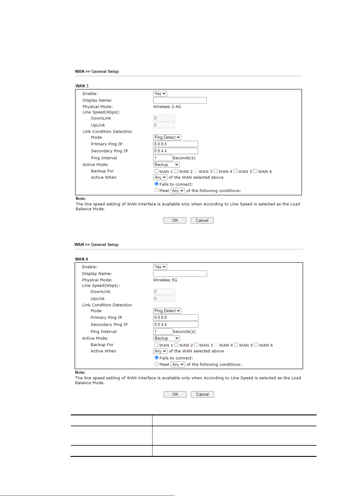
IIII--11--11--33 WWAANN33//WWAANN44 ((WWiirreelleessss 22..44GG oorr 55GG))
WAN3/WAN4 can be configured for physical mode of Wireless 2.4G or Wireless 5G.
or
Available settings are explained as follows:
Item Description
Enable Yes - WAN is enabled.
No - WAN is disabled.
Display Name Optional name to identify the WAN. Enter the description
Vigor2865 Series User’s Guide
73
Page 88

4
for the interface.
Physical Mode Physical connection used for this WAN.
Wireless 2.4G - WAN connection to be established through
2.4GHz Wi-Fi.
Wireless 5G - WAN connection to be established through
5GHz Wi-Fi.
Line Speed (Kbps) It determines the ratio of outbound connections made by
the router across all active WANs. The Line Speed on
WAN>>General Setup must first be set to According to
Line Speed before these values can be changed.
DownLink - WAN downlink speed.
UpLink - WAN uplink speed.
Link Condition Detection In order for the system to detect the latency, jitter, and
packet-loss status for each WAN interface, you have to
specify the IP transmitting data through the interface.
Mode - Choose Ping Detect, Http Detect, or Disable as
detection mode. If Ping Detect or Http Detect is selected,
you have to configure the following option.
Primary Ping IP - Enter an IP address.
Secondary Ping IP - Enter an IP address.
Ping Interval - Set a time interval (unit:second) for the
system to ping the IP address specified above.
Active Mode Always On - WAN is always enabled.
Backup – WAN is enabled only when other WAN ports
specified in Backup For (see below), have lost connection.
Backup For - Select the WANs for which this WAN is
intended to serve as a backup.
Active When - Set the condition for backup
connection.
- Any – The selected WAN(s) will be activated
when any master WAN interface disconnects.
- All – All of the backup WANs will be activated
only when all master WAN interface disconnects.
- Fails to connect – When the active WAN failed,
the WAN selected above will be activated as the
main network connection.
- Meet All/Any of the following conditions –
When the upload traffic, download traffic,
latency, jitter and/or packet loss of active WAN
reaches the traffic threshold (specified here),
the backup WAN will be enabled automatically
to share the overloaded data traffic.
After finished the above settings, click OK to save the settings.
7
Vigor2865 Series User’s Guide
Page 89
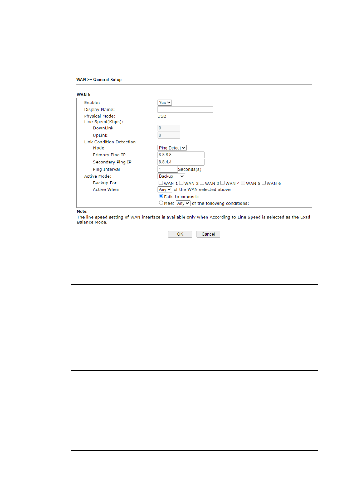
IIII--11--11--44 WWAANN55 // WWAANN66 ((UUSSBB))
To use 3G/4G network connection through 3G/4G USB Modem, please configure WAN5/ WAN6
interface.
Available settings are explained as follows:
Item Description
Enable Yes - WAN is enabled.
No - WAN is disabled.
Display Name Optional name to identify the WAN. Enter the description for
the interface.
Physical Mode Physical connection used for this WAN.
USB - WAN connection to be established through USB.
Line Speed (Kbps) It determines the ratio of outbound conn ections made by the
router across all active WANs. The Line Speed on
WAN>>General Setup must first be set to According to Line
Speed before these values can be changed.
DownLink - WAN downlink speed.
UpLink - WAN uplink speed.
Link Condition Detection In order for the system to detect the latency, jitter, and
packet-loss status for each WAN interface, you have to
specify the IP transmitting data through the interface.
Mode - Choose Ping Detect, Http Detect, or Disable as
detection mode. If Ping Detect or Http Detect is selected,
you have to configure the following option.
Primary Ping IP - Enter an IP address.
Secondary Ping IP - Enter an IP address.
Ping Interval - Set a time interval (unit:second) for the
system to ping the IP address specified above.
Vigor2865 Series User’s Guide
75
Page 90

Active Mode Always On - WAN is always enabled.
Backup – WAN is enabled only when other WAN ports
specified in Backup For (see below), have lost connection.
Backup For - Select the WANs for which this WAN is
intended to serve as a backup.
Active When - Set the condition for backup connection.
- Any – The selected WAN(s) will be activated when
any master WAN interface disconnects.
- All – All of the backup WANs will be activated only
when all master WAN interface disconnects.
- Fails to connect – When the active WAN failed,
the WAN selected above will be activated as the
main network connection.
- Meet All/Any of the following conditions – When
the upload traffic, download traffic, latency,
jitter and/or packet loss of active WAN reaches
the traffic threshold (specified here), the backup
WAN will be enabled automatically to share the
overloaded data traffic.
After finished the above settings, click OK to save the settings.
76
Vigor2865 Series User’s Guide
Page 91
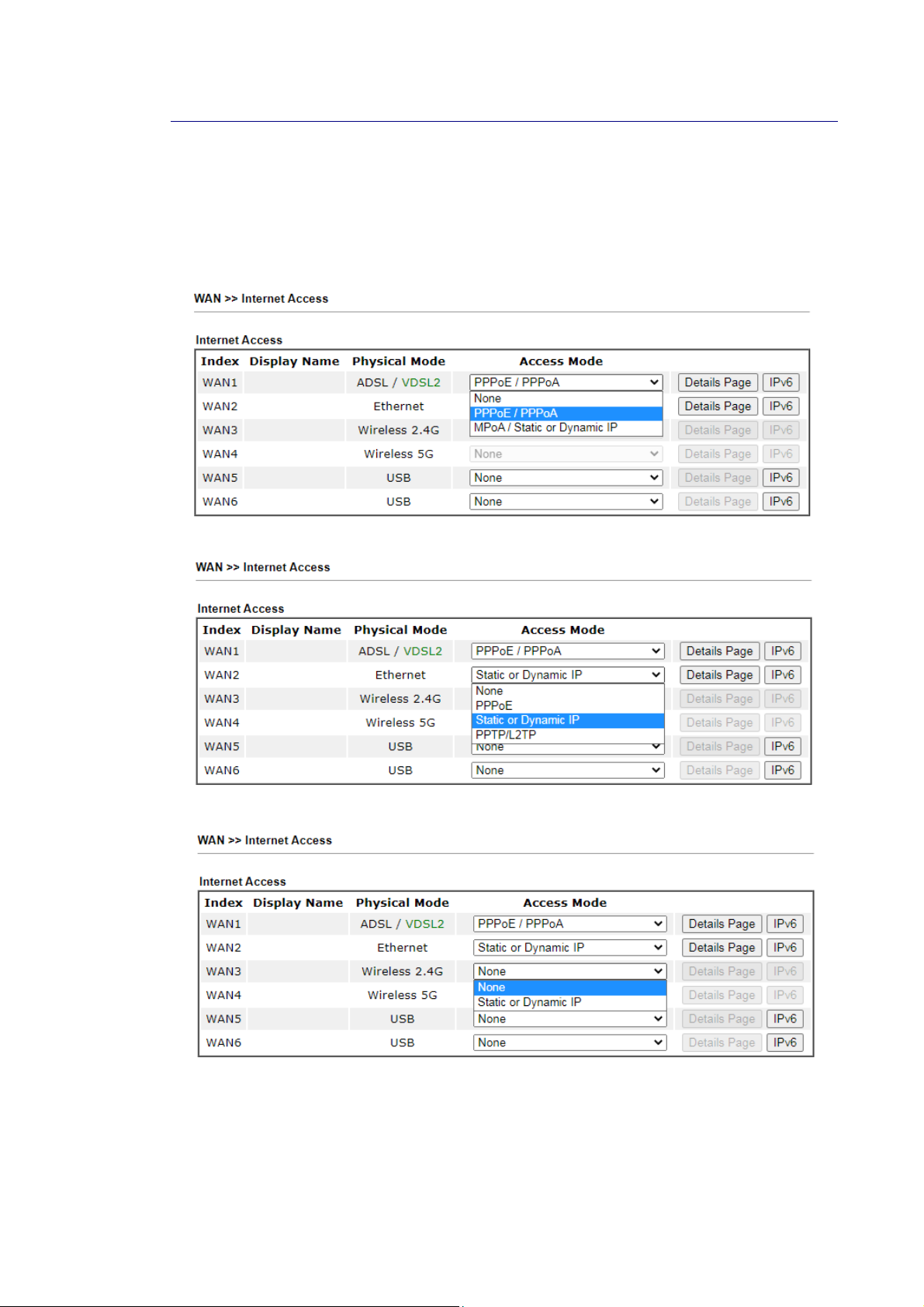
7
IIII--11--22 IInntteerrnneett AAcccceessss
For the router supports multi-WAN function, the users can set different WAN settings (for
WAN1, WAN2, WAN3 or LTE, WAN4, WAN5, WAN6) for Internet Access. Due to different
Physical Mode for WAN interface, the Access Mode for these connections also varies. Refer t o
the following figures for examples.
Access Mode for ADSL/VDSL2,
Access Mode for Ethernet,
Access Mode for Wireless 2.4G/5G,
Vigor2865 Series User’s Guide
7
Page 92
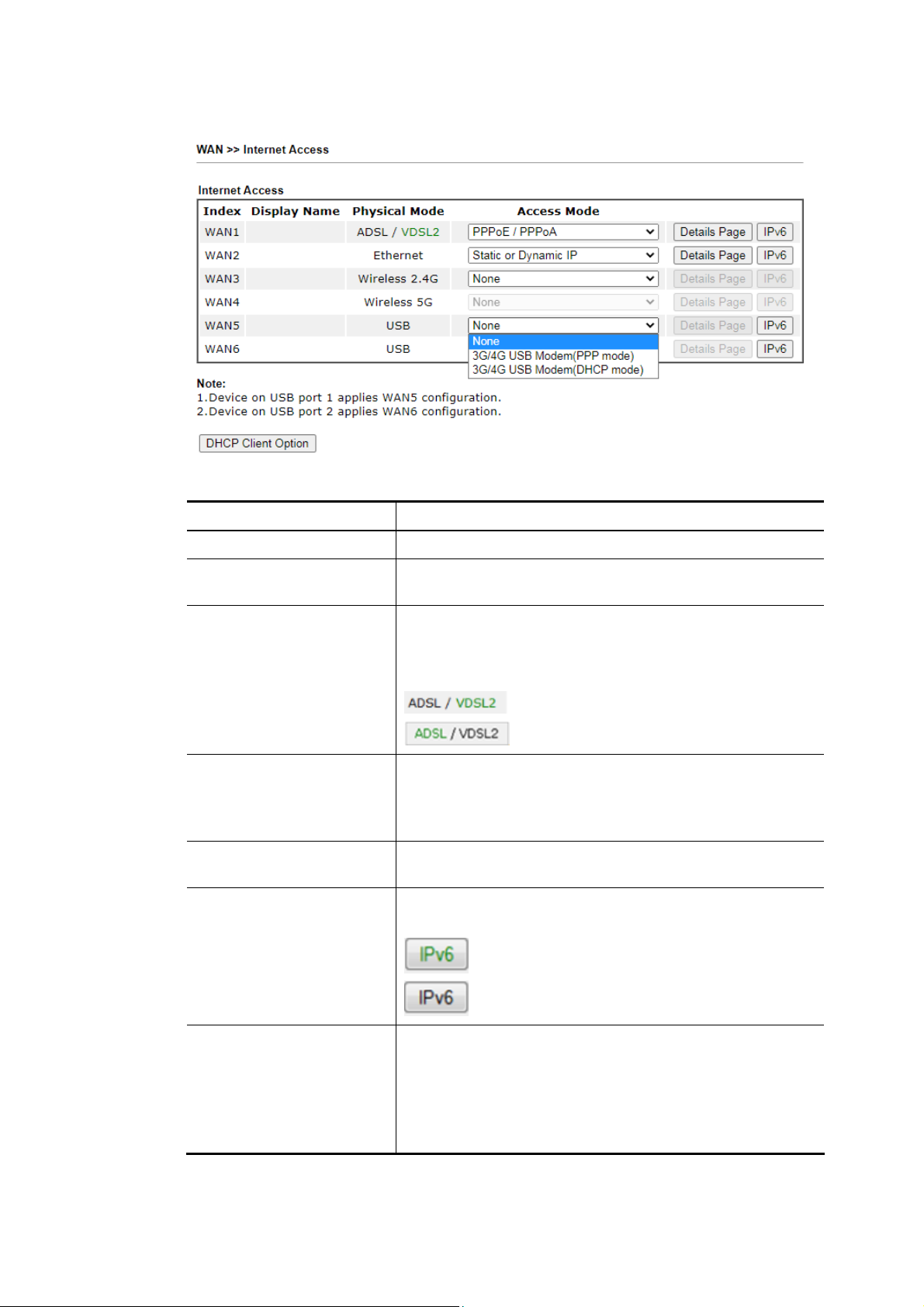
Access Mode for USB,
Available settings are explained as follows:
Item Description
Index The WAN interface.
Display Name Reflects the Display Name configured for the WAN in the
General Setup section.
Physical Mode Reflects the Physical Mode configured for the WAN in the
General Setup section.
For WAN1, the currently active physical mode is shown in
green:
- VDSL2 is being used.
- ADSL is being used.
Access Mode Internet access mode of the WAN.
The details page of that mode will be popped up. If not,
click Details Page for accessing the page to configure the
settings.
Details Page Click this button to bring up the Internet Access settings
page.
IPv6 Click this button to bring up the IPv6 settings page.
When IPv6 is enabled, the button label is shown in green:
- IPv6 is enabled.
- IPv6 is disabled.
DHCP Client Option Click this button to configure additional DHCP client
options.
DHCP packets can be processed by adding option number
and data information when such function is enabled and
configured.
78
Vigor2865 Series User’s Guide
Page 93
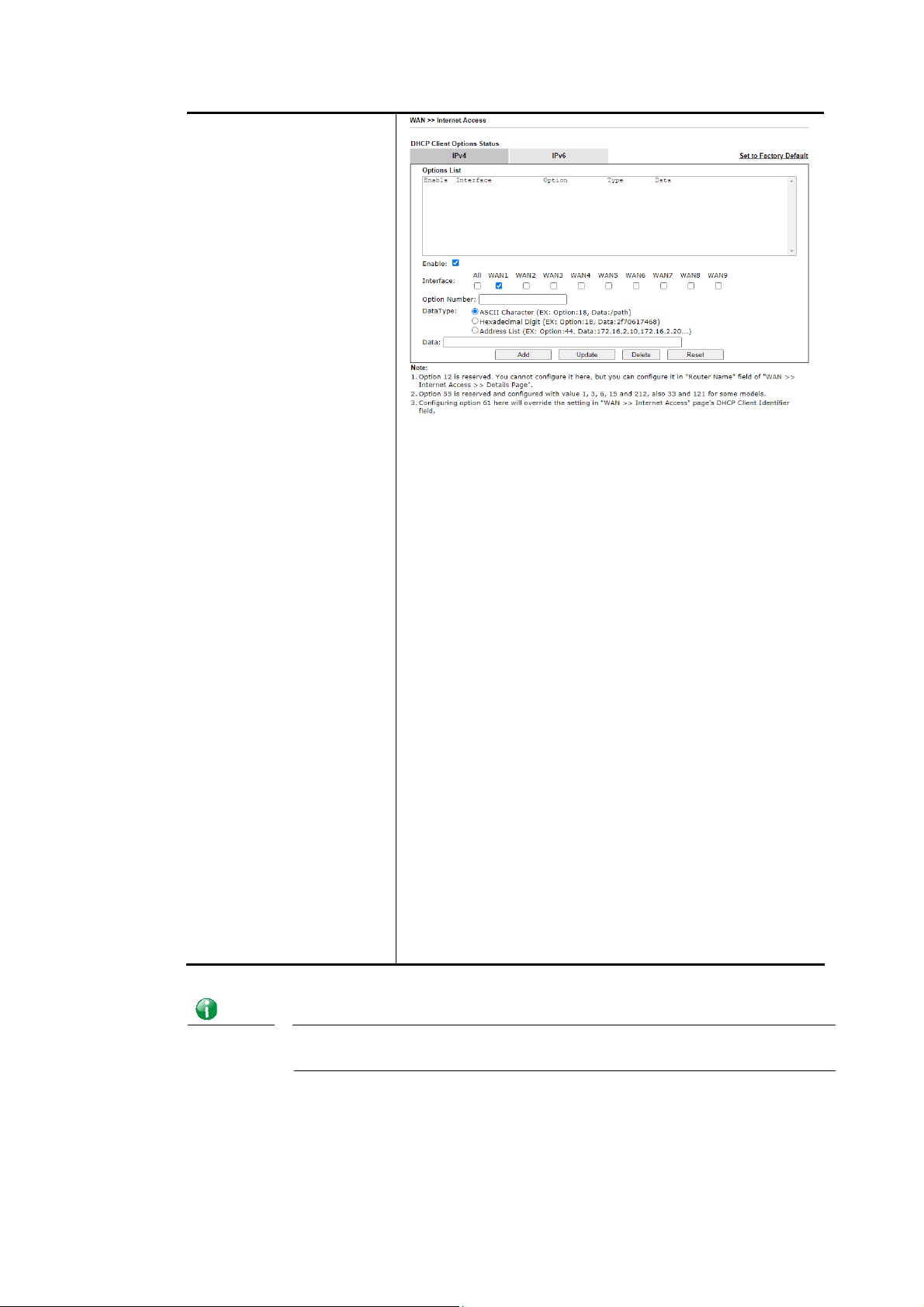
Options List - Shows all the DHCP options that have been
configured in the system.
Enable/Disable – If selected, DHCP option entry is enabled.
If unselected, DHCP option entry is disabled. Each DHCP
option is composed by an option number with data. For
example,
Option number:100
Data: abcd
When it is enabled, the specified values for DHCP option
will be seen in DHCP reply packets.
Interface – WAN interface(s) to which this entry is
applicable. WAN1 through WAN4 are physical WANs that
can be set up in the WAN>>General Setup and
WAN>>Internet Access sections. WAN7 through WAN9 are
virtual WANs that can be set up in the
WAN>>Multi-PVC/VLAN section.
Option Number – Enter a number for this function.
DataType – Choose the type (ASCII or Hex or Address List)
for the data to be stored. Type of data in the Data field:
ASCII Character: A text string. Example: /path.
Hexadecimal Digit: A hexadecimal string. Valid
characters are from 0 to 9 and from a to f. Example:
2f70617468.
Address List: One or more IPv4 addresses, delimited
by commas.
Data – Data of this DHCP option. Enter the content of the
data to be processed by the function of DHCP option.
Info
Vigor2865 Series User’s Guide
If you choose to configure option 61 here, the detailed settings in
WAN>>Interface Access will be overwritten.
79
Page 94
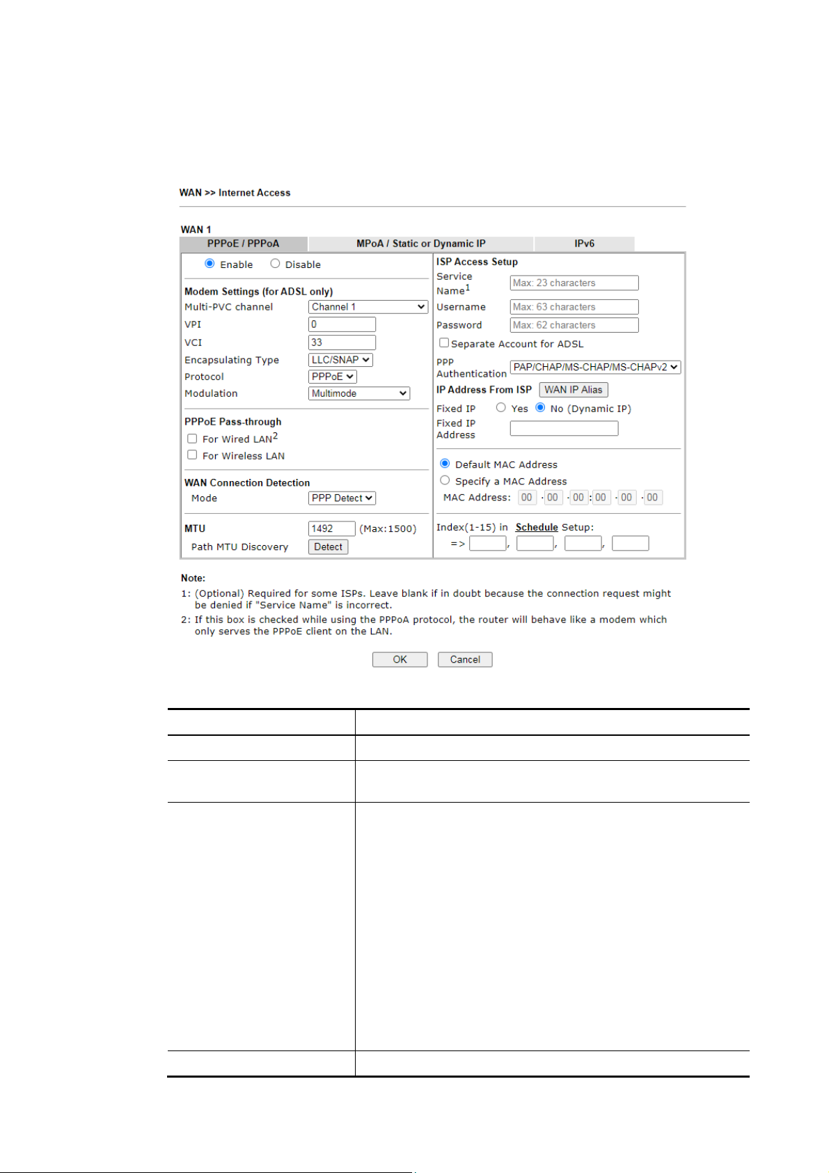
IIII--11--22--11 WWAANN11 DDeettaaiillss PPaaggee ((PPPPPPooEE // PPPPPPooAA,, PPhhyyssiiccaall MMooddee:: VVDDSSLL22))
To choose PPPoE / PPPoA as the accessing protocol of the Internet, please select PPPoE /
PPPoA from the WAN>>Internet Access >>WAN1 page.
Available settings are explained as follows:
Item Description
Enable/Disable Enable or disable PPPoE / PPPoA access mode.
Modem Settings These settings are specific to ADSL. They are not used when
the connection mode is VDSL.
PPPoE Pass-through The router offers PPPoE dial-up connection. Besides, you
also can establish the PPPoE connection directly from local
clients to your ISP via the Vigor router. When PPPoA protocol
is selected, the PPPoE package transmitted by PC will be
transformed into PPPoA package and sent to WAN server.
Thus, the PC can access Internet through such direction.
For Wired LAN – If selected, wired LAN clients can initiate
PPPoE dial-up connections to the WAN.
For Wireless LAN – If selected, wireless LAN clients can
initiate PPPoE dial-up connections to the WAN.
Note: To have PPPoA Pass-through, please choose PPPoA
protocol and check the box(es) here. The router will behave
like a modem which only serves the PPPoE client on the LAN.
That’s, the router will offer PPPoA dial-up connection.
WAN Connection Configures how the WAN connection is monitored.
80
Vigor2865 Series User’s Guide
Page 95
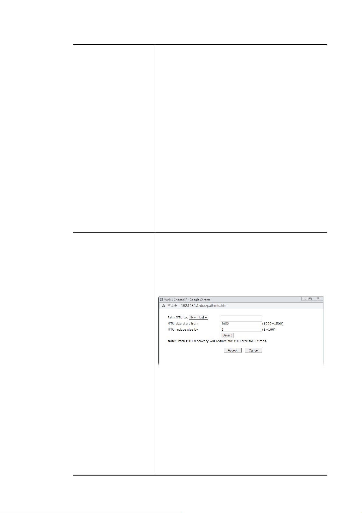
Detection Mode – Choose ARP Detect or Ping Detect for the system to
execute for WAN detection.
ARP Detect - The router broadcasts an ARP request every 5
seconds. If no response is received within 30 seconds, the
WAN connection is deemed to have failed.
Ping Detect - The router sends an ICMP (Internet Control
Message Protocol) echo request every second to the host,
whose address is specified in the Ping IP field, to verify the
WAN connection. If the remote host does not respond within
30 seconds, the WAN connection is deemed to have failed.
If you choose Ping Detect as the detection mode, you have
to enter required settings for the following items.
Primary/Secondary Ping IP – Enter Primary or
Secondary IP address in this field for pinging.
Ping Gateway IP – Enable this setting to use current
WAN gateway IP address for pinging. With the IP
address(es) pinging, Vigor router can check if the WAN
connection is on or off.
TTL (Time to Live) – Time To Live, the maximum
allowed number of hops to the ping destination. Valid
values range from 1 to 255.
Ping Interval – Enter the interval for the system to
execute the PING operation.
Ping Retry – Enter the number of times that the system
is allowed to execute the PING operation before WAN
disconnection is judged.
MTU Maximum Transmission Unit, the size of the largest packet,
in bytes, that can be transmitted to the WAN. The maximum
value is 1500. For PPPoE connections, there is always an
8-byte overhead, so the maximum valid MTU value for PPPoE
is 1492.
Path MTU Discovery – Use this feature to determine the
optimal MTU size for the WAN.
Click Detect to open the following dialog.
Path MTU to – Select Host / IP, for an IPv4 address or
Host / IPv6, for an IPv6 address, and then enter the IP
address in the textbox.
MTU size start from – Determine the starting point
value of the packet.
MTU reduce size by – Number of octets by which to
decrease the 1500-byte MTU. Start with a 0 value for
the reduce size and click the Detect button. If the
message Fail is returned, increase the MTU reduce size
and try again. Repeat until you see the message
Success, indicating that the optimal MTU size has been
reached.
Detect – Click it to detect a suitable MTU value.
Accept – After clicking it, the detected value will be
Vigor2865 Series User’s Guide
81
Page 96
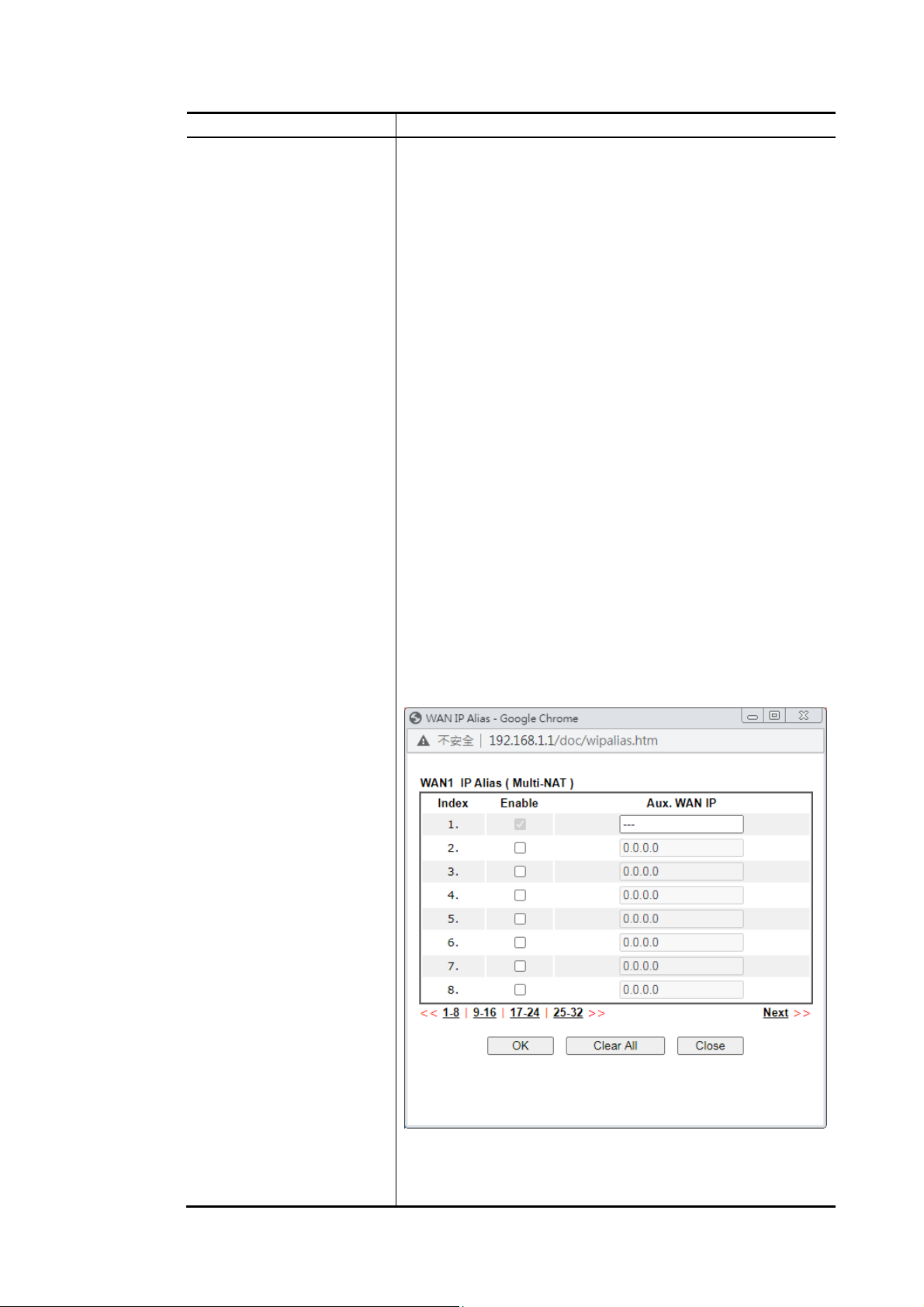
displayed in the field of MTU.
ISP Access Setup Enter your allocated username, password and authentication
parameters according to the information provided by your
ISP.
Service Name - Sets the PPP service name tag. Required by
some ISPs. Leave blank unless instructed otherwise by your
ISP.
Username – Username provided by the ISP for PPPoE/PPPoA
authentication. Maximum length is 63 characters.
Password – Password provided by the ISP for PPPoE/PPPoA
authentication. Maximum length is 62 characters.
Separate Account for ADSL – In default, WAN1 supports
VDSL2/ADSL and uses the same PPPoE account and password
for connection. If ADSL mode requires a separate user name
and password, tick this box and fill out the Username and
Password fields below.
PPP Authentication – The protocol used for PPP
authentication.
PAP only - Only PAP (Password Authentication Protocol)
is used.
PAP or CHAP - Both PAP and CHAP
(Challenge-Handshake Authentication Protocol) can be
used for PPP authentication. Router negotiates with the
PPTP or L2TP server to determine which protocol to
use.
IP Address From ISP - Configure the router according to how
your ISP allocates WAN IP address(es) to you.
WAN IP Alias - Click to enter multiple WAN IP addresses
assigned by your ISP.
Fixed IP – Enter a fixed IP address.
Yes- ISP has assigned a fixed WAN IP address, which is
to be entered below in Fixed IP Address.
82
Vigor2865 Series User’s Guide
Page 97
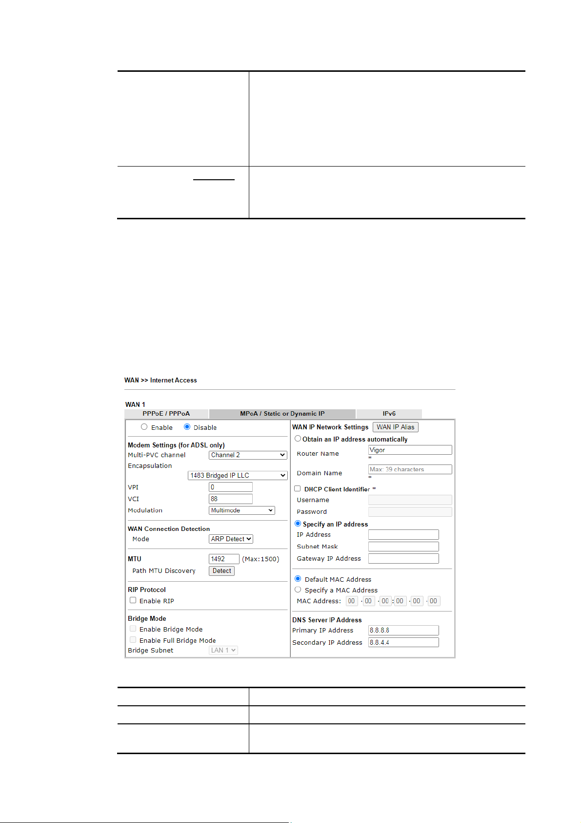
No-WAN IP address is dynamically allocated.
Fixed IP Address – WAN IP address assigned by the ISP.
Default MAC Address – Use the default MAC address for the
WAN Ethernet port.
Specify a MAC Address – Specify a MAC address for the WAN
Ethernet port. Select this option if your ISP authenticates by
MAC addresses.
Index (1-15) in Schedule
Setup
After finished the above settings, click OK to save the settings.
IIII--11--22--22 WWAANN11 DDeettaaiillss PPaaggee ((MMPPooAA//SSttaattiicc oorr DDyynnaammiicc IIPP,, PPhhyyssiiccaall MMooddee::
VVDDSSLL22))
MPoA is a specification that enables ATM services to be integrated with existing LANs, which
use either Ethernet, token-ring or TCP/IP protocols. The goal of MPoA is to allow different
LANs to send packets to each other via an ATM backbone.
To use MPoA/Static or Dynamic IP as the accessing protocol of the Internet, select
MPoA/Static or Dynamic IP from the WAN>>Internet Access >>WAN1 page. The following
web page will appear.
Specify up to 4 time schedule entries to enable or disable the
WAN. All the schedules can be set previously in Applications
>> Schedule web page and you can use the number that you
have set in that web page.
Available settings are explained as follows:
Item Description
Enable/Disable Enable or disable MPoA/Static or Dynamic IP access mode.
Modem Settings These settings are specific to ADSL. They are not used when
the connection mode is VDSL.
Vigor2865 Series User’s Guide
83
Page 98

WAN Connection
Detection
Configures how the WAN connection is monitored.
Mode – Choose ARP Detect, Ping Detect or Always On for
the system to execute for WAN detection.
ARP Detect - The router broadcasts an ARP request
every 5 seconds. If no response is received within 30
seconds, the WAN connection is deemed to have failed.
Ping Detect - The router sends an ICMP (Internet
Control Message Protocol) echo request every second to
the host, whose address is specified in the Ping IP field,
to verify the WAN connection. If the remote host does
not respond within 30 seconds, the WAN connection is
deemed to have failed.
Always On- The router assumes the WAN connection is
always active.
If you choose Ping Detect as the detection mode, you have
to enter required settings for the following items.
Primary/Secondary Ping IP – Enter Primary or Secondary
IP address in this field for pinging.
Ping Gateway IP – Enable this setting to use current WAN
gateway IP address for pinging.
With the IP address(es) pinging, Vigor router can check if
the WAN connection is on or off.
TTL (Time to Live) – Time To Live, the maximum allowed
number of hops to the ping destination. Valid values
range from 1 to 255.
Ping Interval – Enter the interval for the system to
execute the PING operation.
Ping Retry – Enter the number of times that the system is
allowed to execute the PING operation before WAN
disconnection is judged.
MTU Maximum Transmission Unit, the size of the largest packet,
in bytes, that can be transmitted to the WAN. The maximum
value is 1500. For PPPoE connections, there is always an
8-byte overhead, so the maximum valid MTU value for PPPoE
is 1492.
Path MTU Discovery – Use this feature to determine the
optimal MTU size for the WAN.
Click Detect to open the following dialog.
Path MTU to – Select Host / IP, for an IPv4 address or
Host / IPv6, for an IPv6 address, and then enter the IP
address in the textbox.
MTU size start from – Determine the starting point
value of the packet.
MTU reduce size by – Number of octets by which to
decrease the 1500-byte MTU. Start with a 0 value for
84
Vigor2865 Series User’s Guide
Page 99
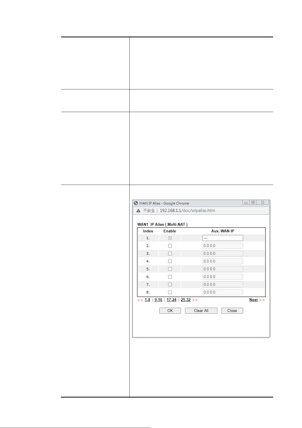
the reduce size and click the Detect button. If the
message Fail is returned, increase the MTU reduce size
and try again. Repeat until you see the message
Success, indicating that the optimal MTU size has been
reached.
Detect – Click it to detect a suitable MTU value.
Accept – After clicking it, the detected value will be
displayed in the field of MTU.
RIP Protocol Routing Information Protocol is abbreviated as RIP(RFC1058).
If selected, the router can exchange routing information
with other routers.
Bridge Mode Enable Bridge Mode - If selected, the router will bridge the
WAN connection to a LAN group.
Enable Full Bridge Mode - If the function is enabled, the
router will work as a bridge modem which is able to forward
incoming packets with VLAN tags.
Enable Firewall – It is available when Bridge Mode is
enabled. When both Bridge Mode and Firewall check boxes
are enabled, the settings configured (user profiles) under
User Management will be ignored. And all of the filter rules
defined and enabled in Firewall menu will be activated.
Bridge Subnet – LAN subnet to be bridged.
WAN IP Network Settings WAN IP Alias - Click to enter multiple WAN IP addresses
assigned by your ISP.
Obtain an IP address automatically – The router receives IP
configuration information from a DHCP server.
Router Name – Used by some ISPs. Contact your ISP for
the appropriate values.
Domain Name –Used by some ISPs. Contact your ISP for
the appropriate values.
DHCP Client Identifier* - Used by some ISPs that
authenticates using DHCP Client Identifier (Option 61). To
enable, tick this box and fill out the Username and Password
Vigor2865 Series User’s Guide
85
Page 100

fields below.
Specify an IP address –Use the IP address, Subnet Mask and
Gateway values specified below.
IP Address –WAN IP address assigned by the ISP.
Subnet Mask –WAN subnet mask.
Gateway IP Address – IP address of the WAN Gateway.
Default MAC Address – Use the default MAC address for the
WAN Ethernet port.
Specify a MAC Address – Specify a MAC address for the WAN
Ethernet port. Select this option if your ISP authenticates by
MAC addresses.
DNS Server IP Address Primary IP Address - IP address of primary DNS server.
Secondary IP Address - IP address of secondary DNS server.
After finishing all the settings here, please click OK to activate them.
86
Vigor2865 Series User’s Guide
 Loading...