

Page 1
Page 2

Vigor2800 Series Quick Start Guide
Copyright Information
Copyright
Declarations
Trademarks
Safety Instructions and Approval
Safety
Instructions
Warranty
Copyright 2005 All rights reserved. This publication contains
information that is protected by copyright. No part may be
reproduced, transmitted, transcribed, stored in a retrieval
system, or translated into any language without written
permission from the copyright holders.
The following trademarks are used in this document:
• Microsoft is a registered trademark of Microsoft Corp.
• Windows, Windows 95, 98, Me, NT, 2000, XP and Explorer
are trademarks of Microsoft Corp.
• Apple and Mac OS are registered trademarks of Apple
Computer Inc.
Other products may be trademarks or registered trademarks
of their respective manufacturers.
• Read the installation guide thoroughly before you set up
the router.
• The router is a complicated electronic unit that may be
repaired only be authorized and qualified personnel. Do
not try to open or repair the router yourself.
• Do not place the router in a damp or humid place, e.g. a
bathroom.
• Do not stack the routers.
• The router should be used in a sheltered area, within a
temperature range of +5 to +40 Celsius.
• Do not expose the router to direct sunlight or other heat
sources. The housing and electronic components may be
damaged by direct sunlight or heat sources.
• Keep the package out of reach of children.
• When you want to dispose of the router, please follow local
regulations on conservation of the environment.
We warrant to the original end user (purchaser) that the
router will be free from any defects in workmanship or
materials for a period of three (3) years from the date of
purchase from the dealer. Please keep your purchase
receipt in a safe place as it serves as proof of date of
purchase. During the warranty period, and upon proof of
purchase, should the product have indications of failure due
to faulty workmanship and/or materials, we will, at our
discretion, repair or replace the defective products or
i
Page 3

Be a
Registered
Owner
Firmware &
Tools Updates
components, without charge for either parts or labor, to
whatever extent we deem necessary tore-store the product
to proper operating condition. Any replacement will consist
of a new or re-manufactured functionally equivalent product
of equal value, and will be offered solely at our discretion.
This warranty will not apply if the product is modified,
misused, tampered with, damaged by an act of God, or
subjected to abnormal working conditions. The warranty
does not cover the bundled or licensed software of other
vendors. Defects which do not significantly affect the
usability of the product will not be covered by the warranty.
We reserve the right to revise the manual and online
documentation and to make changes from time to time in the
contents hereof without obligation to notify any person of
such revision or changes.
Web registration is preferred. You can register your Vigor
router via http://www.draytek.com. Alternatively, fill in the
registration card and mail it to the address found on the
reverse side of the card.
Due to the continuous evolution of DrayTek ADSL & Router
technology, all routers will be regularly upgraded. Please
consult the DrayTek web site for more information on newest
firmware, tools and documents.
http://www.draytek.com
ii
Page 4

European Community Declarations
Manufacturer: DrayTek Corp.
Address: No. 26, Fu Shing Road, HuKou County, HsinChu Industrial Park,
Hsin-Chu, Taiwan 303
Product: Vigor2800 Series ADSL2/2+ Routers
DrayTek Corp. declares that Vigor2800 series of routers are in compliance with
the following essential requirements and other relevant provisions of R&TTE
Directive 1999/5/EEC.
The product conforms to the requirements of Electro-Magnetic Compatibility
(EMC) Directive 89/336/EEC by complying with the requirements set forth in
EN55022/Class B and EN55024/Class B.
The product conforms to the requirements of Low Voltage (LVD) Directive
73/23/EEC by complying with the requirements set forth in EN60950.
The Vigor2800G/Gi are designed for the WLAN 2.4GHz network throughput EC
region, Switzerland, and the restrictions of France.
iii
Page 5

Regulatory Information
Federal Communication Commission Interference Statement
This equipment has been tested and found to comply with the limits for a Class
B digital device, pursuant to Part 15 of the FCC Rules. These limits are designed
to provide reasonable protection against harmful interference in a residential
installation. This equipment generates, uses and can radiate radio frequency
energy and, if not installed and used in accordance with the instructions, may
cause harmful interference to radio communications. However, there is no
guarantee that interference will not occur in a particular installation. If this
equipment does cause harmful interference to radio or television reception,
which can be determined by turning the equipment off and on, the use is
encouraged to try to correct the interference by one of the following measures:
♦ Reorient or relocate the receiving antenna.
♦ Increase the separation between the equipment and receiver.
♦ Connect the equipment into an outlet on a circuit different form that to
which the receiver is connected.
♦ Consult the dealer or an experienced radio/TV technician for help.
This device complies with Part 15 of the FCC Rules. Operation is subject to the
following two conditions:
(1) This device many not cause harmful interference, and
(2) This device may accept any interference received, including interference that
may cause undesired operation.
iv
Page 6

Table of Contents
1. Introduction……………………………………….………………….…………….
1.1
1.2
1.3
1.4
Brief Overview…………………………………………………………..……… 2
Specifications………………………………………………………..…………. 3
Front Panel LEDs and Rear Panel Interfaces………………..……….…… 5
Package Contains……………………………………….…………..…………. 9
2. Quick Install Your Vigor2800 Series Router
2.1
2.2
Hardware Installation……………………………….……………..………….. 10
Configure Your Router via Quick Start Wizard…….……………..………. 11
…………………..……..
10
3. Wireless LAN Settings (for G models)
3.1
3.2
3.3
General Settings…………………………………….…………………..……... 15
Security Settings…………………………………………….……………...…. 16
WDS Settings…………………………………………….……………...……… 17
………….………….……….……
14
4. Trouble Shooting
Is the Hardware Status OK?……………………………………………………. 19
Are the Network Connection Settings on Your PC OK?…………………….. 19
Can You Ping the Router from PC?………………………………..……….… 21
Are the ISP Settings OK?…………………………………………………...…. 22
Back to Factory Default Setting………………………………………………… 23
………………………………………………………..……….
19
1
v
Page 7
1. Introduction
Highlights
z Easy Internet-sharing of your broadband connection
z Robust firewall to help protect your network from external attacks
For G models:
®
z Wireless LAN with data rate up to 108Mbps using Super G
technology
z Secure connection with advanced WPA2 encryption and
authentication
Model comparison chart:
High Speed
Wireless AP
* *
* -
- *
- -
ISDN
Vigor2800Gi
Vigor2800G
Vigor2800i
Vigor2800
ADSL2/2+ Router
*
*
*
*
1
Page 8

1.1 Brief Overview
Targeting requirement for residential, SOHO (Small Office and Home Office)
and business users, the Vigor2800 series are ADSL2/2+ enabled integrated
access device. With downstream speed up to 12Mbps (ADSL2) or 24Mbps
(ADSL2+), the Vigor2800 series provide exceptional bandwidth* for Internet
access. (*note: the available bandwidth also depends on the Internet Service Provider)
Embedded with sophistic VPN firewall security features, the Vigor2800 series
provide 32 dedicated virtual private data networks tunneling through public
Internet. Powered by hardware-based DES/3DES engine, all the information
transmitted is well encrypted. Hence Vigor2800 series can against any
snooping without performance degraded when VPN is enabled.
The Vigor2800 G models are embedded 802.11g compliant wireless module
which provides wireless LAN access with line rate as much as 54Mbps. The
Vigor2800 G models feature WPA2 (802.11i), wireless LAN isolation, WDS
(Wireless Distribution System), and Universal VLAN™. The Vigor2800 i
models provide ISDN backup, which keep your internet access alive even
when ADSL internet access fails.
2
Page 9

1.2 Specifications
For Vigor2800 G models
Wireless Access Point
IEEE802.11b/g compliant
¾ 64/128-bit WEP
¾ WPA/WPA2(IEEE802.11i)
¾ 802.1x authentication with
RADIUS client
VPN over WLAN
Wireless client list
Hidden SSID
MAC address access control
Access point discovery
Wireless VLAN*
Wireless LAN isolation
Wireless client isolation
Wireless rate-control*
Super G TM
¾ Up to 108 Mbps data rate **
¾ Utilizing adaptive radio to
automatically identify clear
channels
¾ Real-time hardware data
compression
¾ Fast Frames
standards-compliant bursting
* *Actual data throughput will vary
according to the network conditions and
environmental factors, including volume of
network traffic, network overhead and
building materials.
WDS (Wireless Distribution
System)
For Vigor2800 i models All models
TM
and
ISDN
Euro ISDN compatible
Automatic ISDN backup
Support
64/128Kbps(multilink-PPP)/BOD
(Bandwidth on Demand)
Remote Dial-In/LAN-to-LAN
connection
Remote activation
Virtual TA
ADSL Compliant
ADSL
¾ G.dmt (G.992.1)
¾ G.lite (G.992.2)
¾ ANSI T1.413 issue2
ADSL2
¾ G.dmt.bis(G.992.3)
¾ G.lite.bis(G.992.4)
ADSL2+(G.992.5)
Up to 24Mbps downstream and
1Mbps upstream
ATM Protocols
Multiple Protocol over AAL5 (RFC
2684)
PPP over Ethernet and AAL5
(RFC 2516,2364)
Up to 8 PVC
PPPoE pass through LAN/WLAN
Transparent bridge for MPoA
3
Page 10

VPN
Up to 32 VPN tunnels
Supported protocol: PPTP,
IPSec, L2TP, L2TP over IPSec
DHCP over IPSec(*)
Encryption: AES, MPPE and
hardware-based DES/3DES
Authentication: MD5, SHA-1
IKE authentication: pre-shared
key and digital signature(X.509)*
LAN-to-LAN, Teleworker-to-LAN
Firewall Facilities
IM/P2P blocking
Multi-NAT, DMZ host,
port-redirect/open port
Rule-based packet filtering
Stateful packet inspection
DoS/DDoS protection
IP address anti-spoofing
E-mail alert and logging via
syslog
VPN pass through
QoS
Class-based bandwidth
guarantee by user-defined traffic
categories
Support 4 priority levels
Support of DiffServ Code Point
classifying
Printer Server
One USB port connector
Built-in LPR printer server
Provide LPR printer for Windows
98/SE/ME
Compatible with Windows
2000/XP/Server 2003/MAC OS
9/MAC OS X built-in LPR printer
driver
Network Features
DHCP client/relay/server
Dynamic DNS
SNTP client
Call scheduling
RADIUS client
DNS cache/proxy
UPnP
Routing protocol:
¾ Static routing
¾ RIP V2
Router Management
Web-based user interface
(HTTP/HTTPS)
Quick Start Wizard
CLI (Command Line Interface,
Telnet/SSH*)
Administration access control
Configuration backup/restore
Built-in diagnostic function
Firmware upgrade via TFTP/FTP
Syslog
SNMP management MIB-II
Content Filtering
URL blocking
Java Applet, Cookies, Active X,
compressed, executable,
multimedia
Time schedule control
Power Consumption
15Watt Max.
*future release
4
Page 11

1.3 Front Panel LEDs and Rear Panel Interfaces
1.3.1 Vigor2800Gi
LED Status Explanation
ACT (Activity) blinking The router is powered on and running properly.
ISDN
P2P
Firewall
WLAN
DSL
Printer
LAN
(P1, P2, P3,
P4)
Interface Description
Printer
PWR
P1, P2, P3, P4
DSL
ISDN
Factory Reset
on The ISDN network is correctly setup.
blinking A successful remote connection on the ISDN BRI B1/B2
channel.
on The P2P function is active
blinking When starting to prohibit P2P data
on The DoS function is enabled.
blinking When encountered DoS attacks.
on The wireless LAN function is enabled.
blinking Ethernet packets are transmitting over wireless LAN.
on The ADSL,ADSL2/2+ line is showtime.
on The USB interface printer is ready.
orange A normal 10Mbps connection is through its corresponding
port.
green A normal 100Mbps connection is through its corresponding
port.
blinking Ethernet packets are transmitting.
Connect to the USB printer.
Connect the included power adapter to the power outlet.
Connect to the local networked devices.
Connect the ADSL,ADSL2/2+ line to access the Internet.
Connect to the NT1 (or NT1+) box provided by ISDN service provider.
Restore the default settings.
Usage: Turn on the router (ACT LED is blinking), press the hole and
keep for more than 5 seconds. When the ACT LED begins to blink
rapidly, release the button. Then the router will restart with the factory
default configuration.
5
Page 12

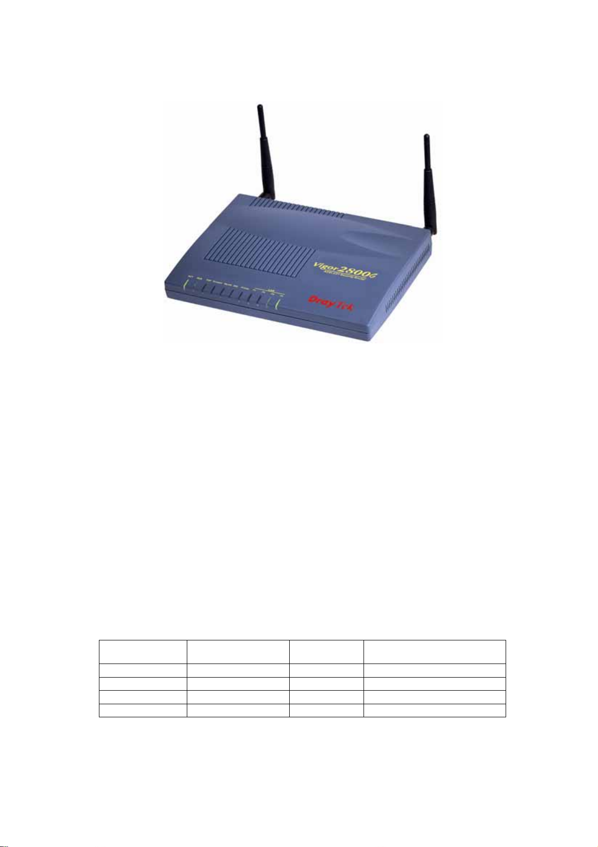
1.3.2 Vigor2800G
LED Status Explanation
ACT (Activity) blinking The router is powered on and running properly.
QoS
P2P
on The QoS function is active.
on The P2P function is active
blinking When starting to prohibit P2P data
Firewall
on The DoS function is enabled.
blinking When encountered DoS attacks.
WLAN
on The Wireless LAN function is enabled.
blinking Ethernet packets are transmitting over wireless LAN.
DSL
Printer
LAN
(P1, P2, P3,
P4)
on The ADSL,ADSL2/2+ line is showtime.
on The USB interface printer is ready.
orange A normal 10Mbps connection is through its corresponding
port.
green A normal 100Mbps connection is through its corresponding
port.
blinking Ethernet packets are transmitting.
Interface Description
Printer
PWR
P1, P2, P3, P4
DSL
Factory Reset
Connect to the USB printer.
Connect the included power adapter to the power outlet.
Connect to the local networked devices.
Connect the ADSL,ADSL2/2+ line to access the Internet.
Restore the default settings.
Usage: Turn on the router (ACT LED is blinking), press the hole and
keep for more than 5 seconds. When the ACT LED begins to blink
rapidly, release the button. Then the router will restart with the factory
default configuration.
6
Page 13

1.3.3 Vigor2800i
LED Status Explanation
ACT (Activity) blinking The router is powered on and running properly.
ISDN
P2P
Firewall
VPN
DSL
Printer
LAN
(P1, P2, P3,
P4)
Interface Description
Printer
PWR
P1, P2, P3, P4
DSL
ISDN
Factory Reset
on The ISDN network is correctly setup.
blinking A successful remote connection on the ISDN BRI B1/B2
channel.
on The P2P function is active
blinking When starting to prohibit P2P data
on The DoS function is enabled.
blinking When encountered DoS attacks.
on The VPN tunnel is launched.
on The ADSL,ADSL2/2+ line is showtime.
on The USB interface printer is ready.
orange A normal 10Mbps connection is through its corresponding
port.
green A normal 100Mbps connection is through its corresponding
port.
blinking Ethernet packets are transmitting.
Connect to the USB printer.
Connect the included power adapter to the power outlet.
Connect to the local networked devices.
Connect the ADSL,ADSL2/2+ line to access the Internet.
Connect to the NT1 (or NT1+) box provided by ISDN service provider.
Restore the default settings.
Usage: Turn on the router (ACT LED is blinking), press the hole and
keep for more than 5 seconds. When the ACT LED begins to blink
rapidly, release the button. Then the router will restart with the factory
default configuration.
7
Page 14

1.3.4 Vigor2800
LED Status Explanation
ACT (Activity) blinking The router is powered on and running properly.
QoS
P2P
Firewall
VPN
DSL
Printer
LAN
(P1, P2, P3,
P4)
on The QoS function is active.
on The P2P function is active
blinking When starting to prohibit P2P data
on The DoS function is enabled.
blinking When encountered DoS attacks.
on The VPN function is active.
on The ADSL,ADSL2/2+ line is showtime.
on The USB interface printer is ready.
orange A normal 10Mbps connection is through its corresponding
port.
green A normal 100Mbps connection is through its corresponding
port.
blinking Ethernet packets are transmitting.
Interface Description
Printer
PWR
P1, P2, P3, P4
DSL
Factory Reset
Connect to the USB printer.
Connect the included power adapter to the power outlet.
Connect to the local networked devices.
Connect the ADSL,ADSL2/2+ line to access the Internet.
Restore the default settings.
Usage: Turn on the router (ACT LED is blinking), press the hole and
keep for more than 5 seconds. When the ACT LED begins to blink
rapidly, release the button. Then the router will restart with the factory
default configuration.
8
Page 15

1.4 Package Contains
Quick Start Guide CD
UK-type power adapter EU-type power adapter
USA/Taiwan-type power
adapter
RJ-45 Cable (Ethernet)
AU/NZ-type power adapter
RJ-45 to RJ-45 (ISDN) for
Vigor2800 i models
RJ-11 to RJ-45 (Annex B)
Antennas for V2800 G models
or
RJ-11 Cable (Annex A / B)
RJ-11 Cable (PSTN line)
9
Page 16

2. Quick Install Your Vigor2800 Series Router
2.1 Hardware Installation
Before starting to configure the router, you have to connect your devices
correctly.
1. Connect the DSL interface to the external ADSL splitter with an ADSL line
cable.
2. Connect one port of 4-port switch to your computer with a RJ-45 cable.
3. For G models, connect detachable antennas to the router.
4. Connect the attached power adapter to the power port.
5. Check the ACT and WAN, LAN LEDs to assure network connections.
(Regarding the detailed LED status explanation, please refer to section 1.3)
10
Page 17

2.2 Configure Your Router via Quick Start Wizard
Introduction
The Quick Start Wizard is designed for you to easily set up your broadband
Internet access. You can directly access the Quick Start Wizard via Web
Configurator.
Configure Your Router via Quick Start Wizard
Step 1.
First make sure your PC connects to router correctly. You may either
simply set up your PC to dynamic get IP from router or set up the IP
address of PC to be the same subnet as the default IP address of
Vigor router 192.168.1.1. If you don’t know how, please refer to Trouble
Shooting.
Then open the web browser on the PC. Type http://192.168.1.1. If your
link is successful, a pop-up window will open to ask for username and
password. Leave the default null value and press OK to continue.
Step 2.
If you fail to access to the web configuration, please refer to “Trouble
Shooting” guide.
The Main Menu will pop out after completing previous step.
11
Page 18

Step 3.
Now Quick Start Wizard is switched on. Enter login password. Then
click Next to continue.
Step 4
Step 5
Select the appropriate Internet access type according to the information
from your ISP. Or Clicking “Auto detect” button also offers the related
DSL parameters automatically.
If PPPoE/PPPoA is selected, please manually enter the
Username/Password provided by your ISP service provider. Checking
the Always On means Internet access is always on regardless of
Internet usage.
12
Page 19

Step 6
Review the summary of settings.
On the bottom of Web Configurator window, you can find messages showing the
system interaction with you.
z “Ready” indicates the system is ready for you to input settings.
z “Settings Saved” means your settings are saved once you click “Finish” or
“OK” button.
13
Page 20

3. Wireless LAN Settings(for G models)
Select from the menu of the Wireless LAN:
Wireless LAN >> General Settings
Security
Access Control
WDS Settings
Access Point Discovery
Station List
(The default value of Frequency Domain was set by factory depends on the
reselling region.)
Wireless Distribution System
Wireless Distribution System(WDS) is an advanced technology to link 2 LANs or
2 WLANs through air, if router is set in Bridge Mode, or to extend a Wireless
LAN coverage area, if router is set in Repeater Mode
Example Application 1
Example Application 2
14
Page 21

3.1 General Settings
Click General Settings to configure the Service Set Identifier (SSID) and
wireless channel.
1. Enable Wireless LAN:
Check the box to enable wireless function.
2. Mode:
Select an appropriate wireless mode.
Mixed
(11b+11g+SuperG)
The radio can support both IEEE802.11b, IEEE802.11g and
Super G protocols simultaneously.
Mixed (11b+11g)
Super G only
11g-only
11b-only
The radio can support both IEEE802.11b and IEEE802.11g
protocols simultaneously.
The radio only supports Super G protocol.
The radio only supports IEEE802.11g protocol.
The radio only supports IEEE802.11b protocol.
3. Scheduler:
Set the wireless LAN to work at some time interval only. Choose up to 4
out of 15 schedules as defined in Applications > Call Schedule Setup.
4. SSID and Channel:
The default SSID is "default". We suggest you change it to a particular
name.
SSID(service set
identifier)
Channel
It is used to name the wireless LAN, and must have the
same content in client PC/notebook wireless card(s). SSID
can be any text numbers or various special characters.
A wireless channel for the router. The default channel is 6.
You can change it to more appropriate one if the selected
channel is under serious interference.
5. Hide SSID:
Check it to be invisible against other’s malicious scanning.
15
Page 22

3.2 Security
Click Security to configure the security options.
1. Mode:
Select an appropriate encryption to improve the security and privacy of
your wireless data packets.
Disable
WEP Only
WEP/802.1x Only
WEP or WPA/PSK
WEP/802.1x or WPA/802.1x
WPA/PSK Only
Turn off the encryption mechanism.
Accepts only WEP clients and the encryption
key should be entered in WEP Key.
Accepts only WEP clients. The authentication
will be 802.1x and the encryption key will be
automatically negotiated. Please set RADIUS
server.
Accepts WEP and WPA clients simultaneously
and the encryption key should be entered in
WEP Key and PSK respectively.
Accepts only WEP or WPA clients. The
authentication will be 802.1x and the encryption
key will be automatically negotiated. Please set
RADIUS server.
Accepts only WPA clients and the encryption
key should be entered in PSK.
16
Page 23

WPA/802.1x Only
Accepts only WPA clients. The authentication
will be 802.1x and the encryption key will be
automatically negotiated. Please set RADIUS
server.
2. WPA:
If you select WPA in Mode, then select the Type of WPA here.
Type
Pre-Shared Key(PSK)
Select from Mixed(WPA+WPA2) or WPA2 only.
Either 8~63 ASCII characters or 64
Hexadecimal digits leading by 0x can be
entered. For example "0123456789ABCD...." or
"0x321253abcde.....".
3. WEP:
64-Bit
128-Bit
To communicate, all wireless devices must support the same
encryption bit size and have the same key. If WEP, only one key out
of four preset keys can be selected at one time.
Either 5 ASCII characters or 10 hexadecimal
digitals leading by 0x can be entered. For
example, ABCDE or 0x4142434445.
Either 13 ASCII characters or 26 hexadecimal
digits leading by 0x can be entered. For
example, ABCDEFGHIJKLM or
0x4142434445464748494A4B4C4D.
3.3 WDS Settings
Click WDS Settings to configure the WDS functions.
17
Page 24

Mode:
Disable
Bridge
Repeater
1. Security
Select an appropriate encryption to improve the security and privacy of
your WDS data packets.
Disable
WEP
Pre-shared key
2. Access from local WLAN clients
Tick to prohibit access from local WLAN clients.
3. Status
Send a message to test the link.
Turn off the WDS function.
To set this router as in Bridge Mode, which links
its LAN/WLAN to either peer Bridge Mode
router’s LAN/WLAN or peer Repeater Mode
router.
Set peer MAC address at the right column
accordingly.
To set this router as in Repeater Mode, which
forwards packets sending from peer router.
Set peer MAC address at the right column
accordingly.
No encryption will be applied.
Choose from using the same current WEP key
which has been set in Security Settings or
setting a new key.
Set a pre-shared key in TKIP or (AES-)CCMP
encryption. Type 8~63 ASCII characters or 64
hexadecimal digits leading by "0x", for example
"cfgs01a2..." or "0x655abcd....".
18
Page 25

4. Trouble Shooting
This section will guide you to solve abnormal situations. Please follow the
below steps to check your basic installation.
Step 1. Is the Hardware Status OK?
1. Check the power line and WLAN/LAN cable connections. Refer
to the Quick Start Guide “2.1 Hardware Installation” section for
details.
2. Turn on the router, check if the ACT LED blink once per second
and the correspondent LAN LED is bright.
Step 2.
Are the Network Connection Settings on Your PC OK?
The following example is based on Windows XP case. Regarding to
the examples of other OSs, please refer to the similar steps or find
support notes in www.draytek.com.
1. Go to Control Panel and then double-click on Network
Connections.
2. Right-click on Local Area Connection and click on Properties.
19
Page 26

3. Select on Internet Protocol (TCP/IP) and then click Properties.
4. Select Obtain an IP address automatically and Obtain DNS
server address automatically.
20
Page 27

Step 3 Can You Ping the Router from PC?
The default gateway IP address of the router is 192.168.1.1. Please
check that if you can ping the router correctly.
For Windows
1. Open the Command Prompt window (from start menu> Run )
2. Type command (for Windows 95/98/ME) or cmd (for Windows
NT/ 2000/XP).
3. Type ping 192.168.1.1 and press [Enter]
For Mac (Terminal)
The important thing is that the computer receives a reply from
192.168.1.1. If not, please check the IP address of your PC. We
suggest you set the network connection as get IP automatically.
(Please refer to the Step 2)
21
Page 28

Step 4 Are the ISP Settings OK?
Click Internet Access Setup group and then check whether the
ISP settings are set correctly.
For PPPoE/PPPoA Users
1. Check that if the Enable option is selected.
2. Verify if all parameters of DSL Modem Settings are entered
with correct value which given by your ISP.
3. Verify if Username and Password are entered with correct
value which given by your ISP.
For MPoA (RFC1483/2684) Users
1. Check that if the Enable option is selected.
2. Verify if all parameters of DSL Modem Settings are entered
with correct value which given by your ISP.
3. Verify if IP Address, Subnet Mask and Gateway are set
correctly, or that your ISP requires using DHCP clients to
obtain IP automatically.
22
Page 29

Step 5. Back to Factory Default Setting
Warning: After pressing the "factory default setting", you will loose all
settings you did before. Make sure you have recorded all useful settings.
The password of factory default is null.
Software Reset
You can also reset router to factory default via Web configurator.
Hardware Reset
While the router is running (ACT LED blinking), press the button
and hold for more than 5 seconds. The ACT LED begins to blink
rapidly, then release the button. The router will restart with the
factory default configuration.
After restore the factory default setting, please repeat Step 1 to Step
4 to reinstall the router. Configure the router according to your
recorded settings.
If the router does not work correctly, please contact your dealer for help. For any
further questions, please send e-mail to support@draytek.com
23
 Loading...