


Vigor2110 Series
Broadband Firewall Router
User’s Guide
Version: 1.01
Date: 03/07/2009
ii
Vigor2110 Series User’s Guide

Copyright Information
Copyright
Declarations
Trademarks
Copyright 2009 All rights reserved. This publication contains information that is
protected by copyright. No part may be reproduced, transmitted, transcribed, stored in a
retrieval system, or translated into any language without written permission from the
copyright holders.
The following trademarks are used in this document:
z Microsoft is a registered trademark of Microsoft Corp.
z Windows, Windows 95, 98, Me, NT, 2000, XP, Vista and Explorer are
trademarks of Microsoft Corp.
z Apple and Mac OS are registered trademarks of Apple Inc.
z Other products may be trademarks or registered trademarks of their respective
manufacturers.
Safety Instructions and Approval
Safety
Instructions
Warranty
z Read the installation guide thoroughly before you set up the router.
z The router is a complicated electronic unit that may be repaired only be
authorized and qualified personnel. Do not try to open or repair the router
yourself.
z Do not place the router in a damp or humid place, e.g. a bathroom.
z The router should be used in a sheltered area, within a temperature range of +5 to
+40 Celsius.
z Do not expose the router to direct sunlight or other heat sources. The housing and
electronic components may be damaged by direct sunlight or heat sources.
z Do not deploy the cable for LAN connection outdoor to prevent electronic shock
hazards.
z Keep the package out of reach of children.
z When you want to dispose of the router, please follow local regulations on
conservation of the environment.
We warrant to the original end user (purchaser) that the router will be free from any
defects in workmanship or materials for a period of two (2) years from the date of
purchase from the dealer. Please keep your purchase receipt in a safe place as it serves
as proof of date of purchase. During the warranty period, and upon proof of purchase,
should the product have indications of failure due to faulty workmanship and/or
materials, we will, at our discretion, repair or replace the defective products or
components, without charge for either parts or labor, to whatever extent we deem
necessary tore-store the product to proper operating condition. Any replacement will
consist of a new or re-manufactured functionally equivalent product of equal value, and
will be offered solely at our discretion. This warranty will not apply if the product is
modified, misused, tampered with, damaged by an act of God, or subjected to abnormal
working conditions. The warranty does not cover the bundled or licensed software of
other vendors. Defects which do not significantly affect the usability of the product will
not be covered by the warranty. We reserve the right to re vi se the ma nual and onli ne
documentation and to make changes from time to time in the contents hereof without
obligation to notify any person of such revision or changes.
Be a Registered
Owner
Firmware & Tools
Updates
Vigor2110 Series User’s Guide
Web registration is preferred. You can register your Vigor router via
http://www.draytek.com.
Due to the continuous evolution of DrayTek technology, all routers will be regularly
upgraded. Please consult the DrayTek web site for more information on newest
firmware, tools and documents.
http://www.draytek.com
iii

European Community Declarations
Manufacturer: DrayTek Corp.
Address: No. 26, Fu Shing Road, HuKou Township, HsinChu Industrial Park, Hsin-Chu, Taiwan 303
Product: Vigor2110 Series Router
DrayTek Corp. declares that Vigor2110 Series of routers are in compliance with the following essential
requirements and other relevant provisions of R&TTE Directive 1999/5/EEC.
The product conforms to the requirements of Electro-Magnetic Compatibility (EMC) Directive 2004/108/EC by
complying with the requirements set forth in EN55022/Class B and EN55024/Class B.
The product conforms to the requirements of Low Voltage (LVD) Directive 2006/95/EC by complying with the
requirements set forth in EN60950-1.
Regulatory Information
Federal Communication Commission Interference Statement
This equipment has been tested and found to comply with the limits for a Class B digital device, pursuant to Part
15 of the FCC Rules. These limits are designed to provide reasonable protection against harmful interference in a
residential installation. This equipment generates, uses and can radiate radio frequency energy and, if not installed
and used in accordance with the instructions, may cause harmful interference to radio communications. However,
there is no guarantee that interference will not occur in a particular installation. If this equipment does cause
harmful interference to radio or televisi o n recept i on , whi ch can be determined by turning the equipment of f and
on, the user is encouraged to try to correct the interference by one of the following measures:
z Reorient or relocate the receiving antenna.
z Increase the separation between the equipment and receiver.
z Connect the equipment into an outlet on a circuit different from that to which the receiver is connected.
z Consult the dealer or an experienced radio/TV technician for help.
This device complies with Part 15 of the FCC Rules. Operation is subject to the following two conditions:
(1) This device may not cause harmful interference, and
(2) This device may accept any interference received, including interference that may cause undesired operation.
Please visit http://www.draytek.com/user/AboutRegulatory.php
This product is designed for POTS and 2.4GHz WLAN network throughout the EC region and Switzerland with
restrictions in France. Please see the user manual for the applicable networks on your product.
iv
Vigor2110 Series User’s Guide

TTaabbllee ooff CCoonntteennttss
1
Preface ...............................................................................................................1
1.1 Web Configuration Buttons Explanation................................................................................. 1
1.2 LED Indicators and Connectors.............................................................................................. 2
1.2.1 For Vigor2110................................................................................................................... 2
1.2.2 For Vigor2110n................................................................................................................. 4
1.2.3 For Vigor2110Vn............................................................................................................... 6
1.3 Hardware Installation .............................................................................................................. 8
Stand Installation....................................................................................................................... 9
1.4 Printer Installation ................................................................................................................. 10
2
Configuring Basic Settings ............................................................................15
2.1 Two-Level Management........................................................................................................15
2.2 Accessing Web Page............................................................................................................ 15
3
2.3 Changing Password.............................................................................................................. 16
2.4 Quick Start Wizard................................................................................................................ 18
2.4.2 PPPoE ............................................................................................................................ 19
2.4.3 PPTP............................................................................................................................... 20
2.4.4 Static IP........................................................................................................................... 21
2.4.5 DHCP.............................................................................................................................. 22
2.5 Online St atus......................................................................................................................... 23
2.6 Saving Configuration............................................................................................................. 24
U s e r M o d e O p e r a t i o n............................................................................................25
3.1 Internet Access...................................................................................................................... 25
3.1.1 Basics of Internet Protocol (IP) Network......................................................................... 25
3.1.2 PPPoE ............................................................................................................................ 26
3.1.3 Static or Dynamic IP....................................................................................................... 28
3.1.4 PPTP/L2TP..................................................................................................................... 30
3.2 LAN ....................................................................................................................................... 32
3.2.1 Basics of LAN ................................................................................................................. 32
3.2.2 General Setup................................................................................................................. 33
3.3 NAT ....................................................................................................................................... 36
3.3.1 Port Redirection.............................................................................................................. 36
3.3.2 DMZ Host........................................................................................................................ 38
3.3.3 Open Ports...................................................................................................................... 41
3.4 Applications........................................................................................................................... 42
3.4.1 Dynamic DNS................................................................................................................. 42
Vigor2110 Series User’s Guide
v

3.4.2 UPnP............................................................................................................................... 44
3.5 VoIP....................................................................................................................................... 46
3.5.1 DialPlan .......................................................................................................................... 48
3.5.2 SIP Accounts.................................................................................................................. 56
3.5.3 Phone Settings ............................................................................................................... 59
3.5.4 Status.............................................................................................................................. 65
3.6 Wireless LAN ........................................................................................................................ 67
3.6.1 Basic Concepts............................................................................................................... 67
3.6.2 General Setup................................................................................................................. 68
3.6.3 Security........................................................................................................................... 71
3.6.4 Access Control................................................................................................................ 72
3.6.5 Advanced Setting............................................................................................................ 73
3.6.6 WMM Configuration........................................................................................................ 74
3.6.7 Station List...................................................................................................................... 75
3.7 System Maintenance............................................................................................................. 76
3.7.1 System Status................................................................................................................. 76
3.7.2 User Password ............................................................................................................... 77
3.7.3 Time and Date................................................................................................................ 78
3.7.4 Reboot System............................................................................................................... 79
4
3.8 Diagnostics............................................................................................................................ 80
3.8.1 DHCP Table.................................................................................................................... 80
3.8.2 Ping Diagnosis................................................................................................................ 81
3.8.3 Trace Route.................................................................................................................... 81
A d m i n M o d e O p e r a t i o n.........................................................................................83
4.1 Internet Access...................................................................................................................... 83
4.1.1 Basics of Internet Protocol (IP) Network......................................................................... 83
4.1.2 PPPoE ............................................................................................................................ 84
4.1.3 Static or Dynamic IP....................................................................................................... 86
4.1.4 PPTP/L2TP..................................................................................................................... 88
4.2 LAN ....................................................................................................................................... 90
4.2.1 Basics of LAN ................................................................................................................. 90
4.2.2 General Setup................................................................................................................. 92
4.2.3 Static Route.................................................................................................................... 95
4.2.4 VLAN............................................................................................................................... 98
4.2.5 Bind IP to MAC............................................................................................................... 99
4.3 NAT .....................................................................................................................................100
4.3.1 Port Redirection............................................................................................................ 100
4.3.2 DMZ Host...................................................................................................................... 103
4.3.3 Open Ports.................................................................................................................... 105
4.4 Hardware Acceleration........................................................................................................ 107
4.5 Firewall................................................................................................................................ 108
4.5.1 Basics for Firewall......................................................................................................... 108
4.5.2 General Setup............................................................................................................... 110
4.5.3 Filter Setup ................................................................................................................... 112
4.5.4 DoS Defense ................................................................................................................ 117
4.6 Objects Settings..................................................................................................................120
vi
Vigor2110 Series User’s Guide

4.6.1 IP Object....................................................................................................................... 120
4.5.2 IP Group ....................................................................................................................... 122
4.6.3 Service Type Object ..................................................................................................... 124
4.5.4 Service Type Group...................................................................................................... 125
4.6.5 Keyword Object ............................................................................................................ 126
4.5.6 Keyword Group............................................................................................................. 127
4.6.7 File Extension Object.................................................................................................... 128
4.6.8 IM Object ...................................................................................................................... 130
4.6.9 P2P Object.................................................................................................................... 131
4.6.10 Misc Object................................................................................................................. 132
4.7 CSM Profile......................................................................................................................... 133
4.7.1 IM/P2P Filter Profile...................................................................................................... 134
4.7.2 URL Content Filter Profile............................................................................................. 135
4.7.3 Web Content Filter Profile............................................................................................. 139
4.8 Bandwidth Management ..................................................................................................... 141
4.8.1 Sessions Limit............................................................................................................... 141
4.8.2 Bandwidth Limit ............................................................................................................142
4.8.3 Quality of Service.......................................................................................................... 143
4.9 Applications.........................................................................................................................150
4.9.1 Dynamic DNS............................................................................................................... 150
4.9.2 Schedule....................................................................................................................... 152
4.9.3 RADIUS........................................................................................................................ 154
4.9.4 UPnP............................................................................................................................. 155
4.9.5 IGMP............................................................................................................................. 157
4.9.6 Wake on LAN................................................................................................................ 157
4.10 VPN and Remote Access.................................................................................................. 159
4.10.1 Remote Access Control.............................................................................................. 159
4.10.2 PPP General Setup .................................................................................................... 159
4.10.3 IPSec General Setup.................................................................................................. 160
4.10.4 IPSec Peer Identity..................................................................................................... 161
4.10.5 Remote Dial-in User ................................................................................................... 163
4.10.6 LAN to LAN................................................................................................................. 165
4.10.7 Connection Management ........................................................................................... 173
4.11 Certificate Management.................................................................................................... 174
4.11.1 Local Certificate.......................................................................................................... 174
4.11.2 Trusted CA Certificate ................................................................................................ 176
4.11.3 Certificate Backup....................................................................................................... 177
4.12 VoIP................................................................................................................................... 177
4.12.1 DialPlan ...................................................................................................................... 179
4.12.2 SIP Accounts.............................................................................................................. 186
4.12.3 Phone Settings ...........................................................................................................190
4.12.4 Status.......................................................................................................................... 195
4.13 Wireless LAN .................................................................................................................... 196
4.13.1 Basic Concepts........................................................................................................... 196
4.13.2 General Setup............................................................................................................. 198
4.13.3 Security....................................................................................................................... 201
4.13.4 Access Control............................................................................................................ 203
4.13.5 WPS............................................................................................................................ 204
4.13.6 WDS............................................................................................................................ 206
4.13.7 Advanced Setting........................................................................................................ 209
4.13.8 WMM Configuration.................................................................................................... 210
4.13.9 AP Discovery.............................................................................................................. 211
4.13.10 Station List................................................................................................................212
Vigor2110 Series User’s Guide
vii

4.14 System Maintenance......................................................................................................... 214
4.12.1 System Status............................................................................................................. 214
4.14.2 TR-069........................................................................................................................ 215
4.14.3 Administrator Password.............................................................................................. 216
4.14.4 Configuration Backup ................................................................................................. 216
4.14.5 Syslog/Mail Alert.........................................................................................................218
4.14.6 Time and Date............................................................................................................ 220
4.14.7 Management............................................................................................................... 221
4.14.8 Reboot System........................................................................................................... 222
4.14.9 Firmware Upgrade...................................................................................................... 223
4.15 Diagnostics........................................................................................................................ 224
4.15.1 Dial-out Trigger........................................................................................................... 224
4.15.2 Routing Table ............................................................................................................. 225
4.15.3 ARP Cache Table....................................................................................................... 225
4.15.4 DHCP Table................................................................................................................ 226
4.15.5 NAT Sessions Table................................................................................................... 226
4.15.6 Data Flow Monitor....................................................................................................... 227
4.15.7 Ping Diagnosis............................................................................................................ 228
4.15.8 Trace Route................................................................................................................ 229
5
Application and Examples............................................................................231
5.1 Create a LAN-to-LAN Connection Between Remote Office and Headquarter................... 231
5.2 Create a Remote Dial-in User Connection Between the Teleworker and Headquarter...... 238
5.3 QoS Setting Example.......................................................................................................... 242
5.4 LAN – Created by Using NAT ............................................................................................. 245
5.5 Calling Scenario for VoIP Function..................................................................................... 248
5.5.1 Calling via SIP Sever.................................................................................................... 248
5.5.2 Peer-to-Peer Calling..................................................................................................... 250
5.6 Upgrade Firmware for Y our Router..................................................................................... 251
5.7 Request a certificate from a CA server on Windows CA Server......................................... 254
5.8 Request a CA Certificate and Set as Trusted on Windows CA Server............................... 258
Trouble Shooting .........................................................................................261
6.1 Checking If the Hardware Status Is OK or Not....................................................................261
6.2 Checking If the Network Connection Settings on Your Computer Is OK or Not ................. 262
6.3 Pinging the Router from Your Computer............................................................................. 264
6.4 Checking If the ISP Settings are OK or Not........................................................................ 265
6.5 Backing to Factory Default Setting If Necessary ................................................................ 267
6.6 Contacting Your Dealer....................................................................................................... 268
viii
Vigor2110 Series User’s Guide
1
Prreeffaaccee
P
Vigor2110 series is a broadband router. It integrates IP layer QoS, NAT session/bandwidth
management to help users control works well with large bandwidth.
By adopting hardware-based VPN platform and hardware encryption of AES/DES/3DS, the
router increases the performance of VPN greatly, and offers several protocols (such as
IPSec/PPTP/L2TP) with up to 2 VPN tunnels.
The object-based design used in SPI (Stateful Packet Inspection) firewall allows users to set
firewall policy with ease. CSM (Content Security Management) provides users control and
management in IM (Instant Messenger) and P2P (Peer to Peer) more efficiency than before.
By the way, DoS/DDoS prevention and URL/Web content filter strengthen the security
outside and control inside.
Object-based firewall is flexible and allows your network be safe. In addition, through VoIP
function, the communication fee for you and remote people can be reduced.
In addition, Vigor2110 series supports USB interface for connecting USB printer to share
printer or USB storage device for sharing files. Vigor2110 series provides two-level
management to simplify the configuration of network connection. The user mode allows user
accessing into WEB interface via simple configuration. However, if users want to have
advanced configurations, they can access into WEB interface through admin mode.
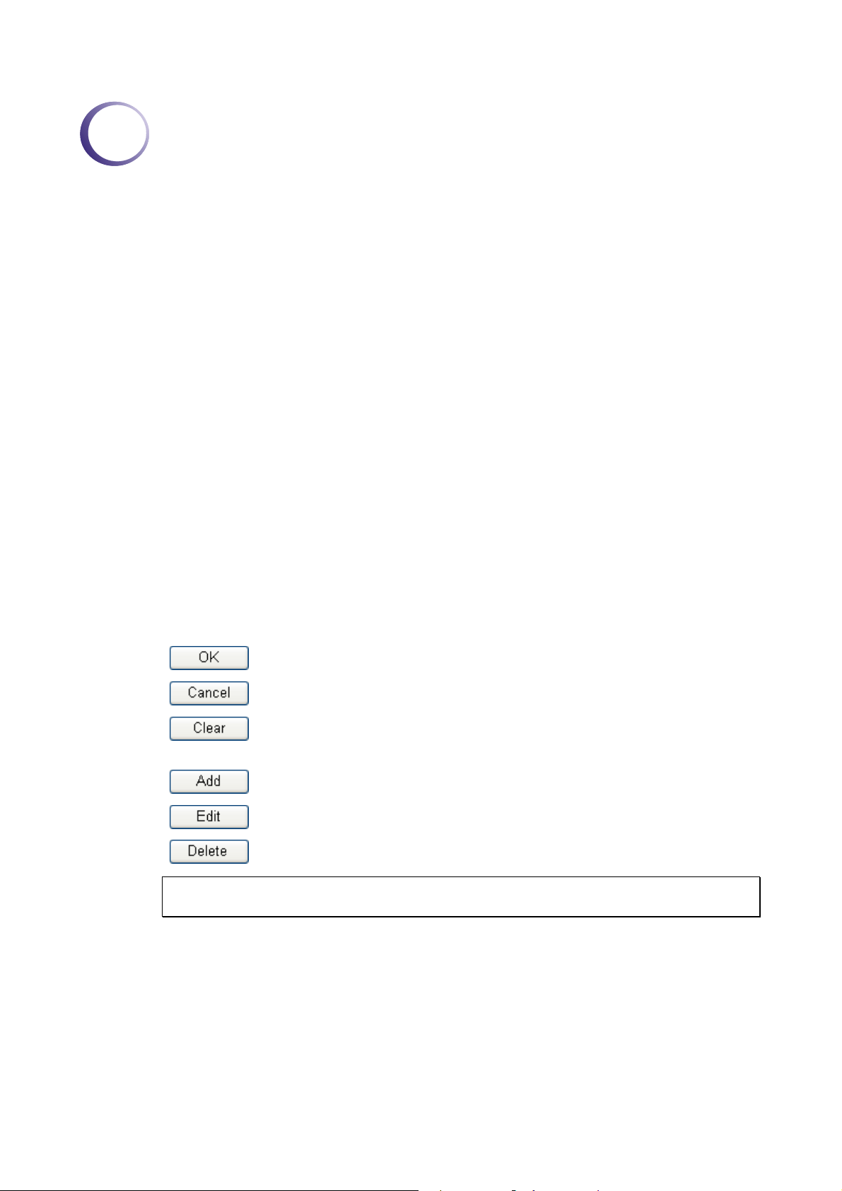
11..11 WWeebb CCoonnffiigguurraattiioonn BBuuttttoonnss EExxppllaannaattiioonn
Several main buttons appeared on the web pages are defined as the following:
Save and apply current settings.
Cancel current settings and recover to the previous saved settings.
Clear all the selections and parameters settings, including selection from
drop-down list. All the values must be reset with factory default settings.
Add new settings for specified item.
Edit the settings for the selected item.
Delete the selected item with the corresponding settings.
Note: For the other buttons shown on the web pages, please refer to Chapter 4 for detailed
explanation.
Vigor2110 Series User’s Guide
1

11..22 LLEEDD IInnddiiccaattoorrss aanndd CCoonnnneeccttoorrss
Before you use the Vigor router, please get acquainted with the LED indicators and connectors
first.
11..22..11 FFoorr VViiggoorr22111100
LED Status Explanation
ACT
(Activity)
CSM On The profile(s) of CSM (Content Security
LAN 1/2/3/4
VPN On The VPN tunnel is active.
QoS
WCF On The profile(s) of CSM (Content Security
Interface Description
WAN Connector for accessing the Internet.
LAN (1-4) Connecters for local networked devices.
USB Connecter for USB storage device (Pen Driver/Mobile
Blinking The router is powered on and running
Off The router is powered off.
On The WAN port is connected. WAN
Blinking It will blink while transmitting data.
On The port is connected.
Off The port is disconnected.
Blinking The data is transmitting.
On A USB device is connected and active. USB
Blinking The data is transmitting.
On The QoS function is active.
On The DoS/DDoS function is active. DoS
Blinking It will blink while detecting an attack.
HD) or printer.
normally.
Management) for IM/P2P, URL/Web
Content Filter application can be enabled
from Firewall >>General Setup. (Such
profile must be established under CSM
menu).
Management) for Web Content Filter
application can be enabled from Firewall
>>General Setup. (Such profile must be
established under CSM menu)
2
Vigor2110 Series User’s Guide

Interface Description
Factory Reset Restore the default settings. Usage: Turn on the router (ACT LED is blinking). Press
the hole and keep for more than 5 seconds. When you see the ACT LED begins to
blink rapidly than usual, release the button. Then the router will restart with the
factory default configuration.
PWR Connector for a power adapter.
ON/OFF
Power Switch.
Vigor2110 Series User’s Guide
3

11..22..22 FFoorr VViiggoorr22111100nn
LED Status Explanation
ACT
(Activity)
LAN 1/2/3/4
VPN On The VPN tunnel is active.
QoS
WPS
WPS Button
Interface Description
WLAN
WAN Connector for accessing the Internet.
LAN (1-4) Connecters for local networked devices.
USB Connecter for USB storage (Pen Driver Mobile/HD) or
Blinking The router is powered on and running
normally.
Off The router is powered off.
On Wireless access point is ready. WLAN
Blinking It will blink while wireless traffic goes
through.
On The WAN port is connected. WAN
Blinking It will blink while transmitting data.
On The port is connected.
Off The port is disconnected.
Blinking The data is transmitting.
On A USB device is connected and active. USB
Blinking The data is transmitting.
On The QoS function is active.
On The DoS/DDoS function is active. DoS
Blinking It will blink while detecting an attack.
On The WPS is on.
Off The WPS is off.
Blinking Waiting for wireless client sending requests
for connection about two minutes.
On Press this button for 2 seconds to wait for
client device making network connection
through WPS. When the LED lights up, the
WPS will be on.
Off The WPS is off.
Blinking Waiting for wireless client sending requests
for connection about two minutes.
Press the button once to enable (WLAN LED on) or
disable (WLAN LED off) wireless connection.
printer.
4
Vigor2110 Series User’s Guide

Interface Description
Factory Reset Restore the default settings. Usage: Turn on the router (ACT LED is blinking). Press the
hole and keep for more than 5 seconds. When you see the ACT LED begins to blink
rapidly than usual, release the button. Then the router will restart with the factory default
configuration.
PWR Connecter for a power adapter.
ON/OFF
Power Switch.
Vigor2110 Series User’s Guide
5

11..22..33 FFoorr VViiggoorr22111100VVnn
LED Status Explanation
ACT
(Activity)
LAN 1/2/3/4
Phone1/
Phone2
Line
WPS
WPS Button
Interface Description
WLAN
WAN Connector for accessing the Internet.
LAN (1-4) Connecters for local networked devices.
USB Connecter for USB storage (Pen Driver Mobile/HD) or
Blinking The router is powered on and running
normally.
Off The router is powered off.
On Wireless access point is ready. WLAN
Blinking It will blink while wireless traffic goes
through.
On The WAN port is connected. WAN
Blinking It will blink while transmitting data.
On The port is connected.
Off The port is disconnected.
Blinking The data is transmitting.
On A USB device is connected and active. USB
Blinking The data is transmitting.
On The phone connected to this port is off-hook.
Off The phone connected to this port is on-hook.
Blinking A phone call comes.
On A PSTN phone call comes (in and out).
However, when the phone call is
disconnected, the LED will be off about six
seconds later.
Off There is no PSTN phone call.
On The WPS is on.
Off The WPS is off.
Blinking Waiting for wireless client sending requests
for connection about two minutes.
On Press this button for 2 seconds to wait for
client device making network connection
through WPS. When the LED lights up, the
WPS will be on.
Off The WPS is off.
Blinking Waiting for wireless client sending requests
for connection about two minutes.
Press the button once to enable (WLAN LED on) or
disable (WLAN LED off) wireless connection.
printer.
6
Vigor2110 Series User’s Guide

Interface Description
Line Connector for PSTN life line.
Phone2/Phone1
Factory Reset Restore the default settings. Usage: Turn on the router (ACT LED is blinking). Press the
PWR Connecter for a power adapter.
ON/OFF
Connecter of analog phone for VoIP communication
hole and keep for more than 5 seconds. When you see the ACT LED begins to blink
rapidly than usual, release the button. Then the router will restart with the factory default
configuration.
Power Switch.
.
Vigor2110 Series User’s Guide
7
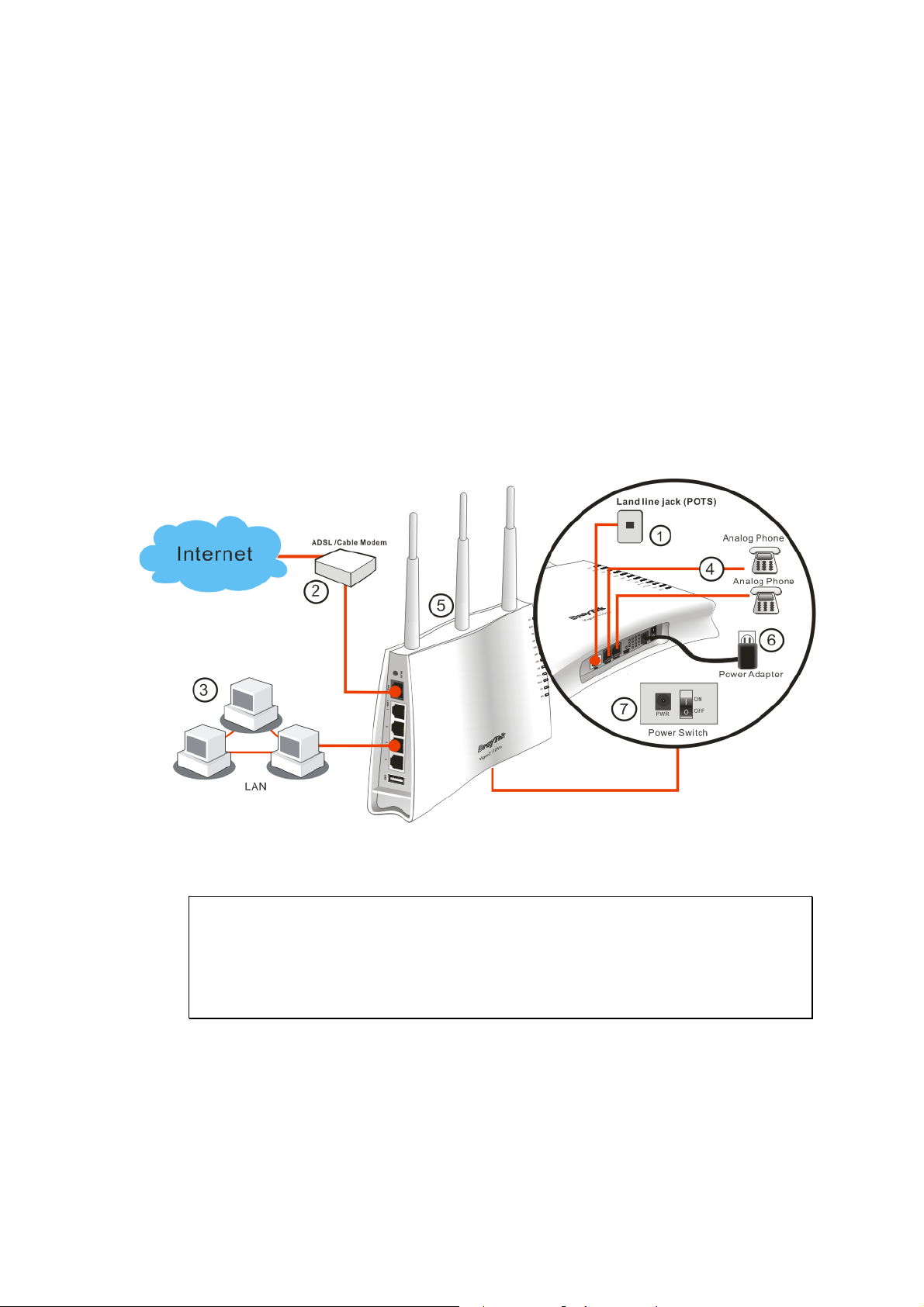
11..33 HHaarrddwwaarree IInnssttaallllaattiioonn
Before starting to configure the router, you have to connect your devices correctly.
1. Connect Line port to land line jack with a RJ-11 cable (Vn model).
2. Connect this device to a modem with a RJ-45 cable.
3. Connect one port of 4-port switch to your computer with a RJ-45 cable. This device
allows you to connect 4 PCs directly.
4. Connect Phone port to a conventional analog telephone.
5. Connect detachable antennas to the router for Vigor2110 series (n model).
6. Connect one end of the power cord to the power port of this device. Connect the other
end to the wall outlet of electricity.
7. Power on the router.
8. Check the ACT and WAN, LAN LEDs to assure network connections.
Caution:
1. Each of the Phone ports can be connected to an analog phone only. Do not connect
the phone ports to the land line jack. Such connection might damage your router.
2. When the power is shutdown, VoIP phone will be disconnected. However, a phone
set connected to Phone 2 port can be used as the traditional telephone for the line will be
guided to land line jack via the router (loop through).
8
Vigor2110 Series User’s Guide

SSttaanndd IInnssttaallllaattiioonn
The Vigor2110 must be placed erectly. Therefore you have to install a stand onto the router to
make it standing firmly. Please follow the figures listed below to finish the installation.
c
e f
d
Vigor2110 Series User’s Guide
9
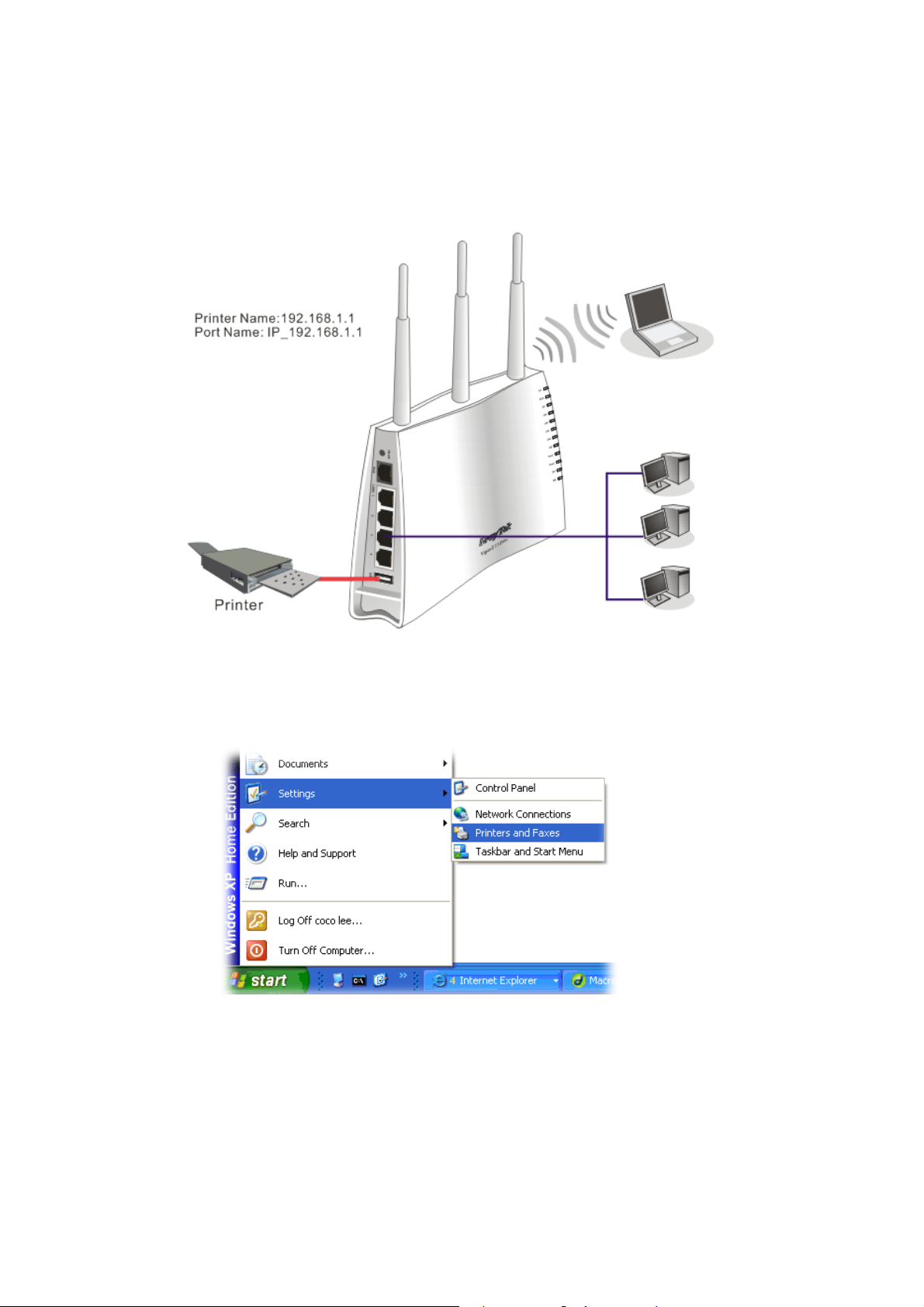
11..44 PPrriinntteerr IInnssttaallllaattiioonn
You can install a printer onto the router for sharing printing. All the PCs connected this router
can print documents via the router. The example provided here is made based on Windows
XP/2000. For Windows 98/SE/Vista, please visit www.draytek.com.
Before using it, please follow the steps below to configure settings for connected computers
(or wireless clients).
1. Connect the printer with the router through USB/parallel port.
2. Open Start->Settings-> Printer and Faxes.
3. Open File->Add Printer. A welcome dialog will appear. Please click Next.
10
Vigor2110 Series User’s Guide

4. Click Local printer attached to this computer and click Next.
5. In this dialog, choose Create a new port Type of port and use the drop down list to
select Standard TCP/IP Port. Click Next.
Vigor2110 Series User’s Guide
11

6. In the following dialog, type 192.168.1.1 (router’s LAN IP) in the field of Printer Name
or IP Address and type IP_192.168.1.1 as the port name. Then, click Next.
7. Click Standard and choose Generic Network Card.
8. Then, in the following dialog, click Finish.
12
Vigor2110 Series User’s Guide

9. Now, your system will ask you to choose right name of the printer that you installed onto
the router. Such step can make correct driver loaded onto your PC. When you finish the
selection, click Next.
10. For the final stage, you need to go back to Control Panel-> Printers and edit the
property of the new printer you have added.
11. Select "LPR" on Protocol, type p1 (number 1) as Queue Name. Then click OK. Next
please refer to the red rectangle for choosing the correct protocol and UPR name.
Vigor2110 Series User’s Guide
13
The printer can be used for printing now. Most of the printers with different manufacturers are
compatible with vigor router.
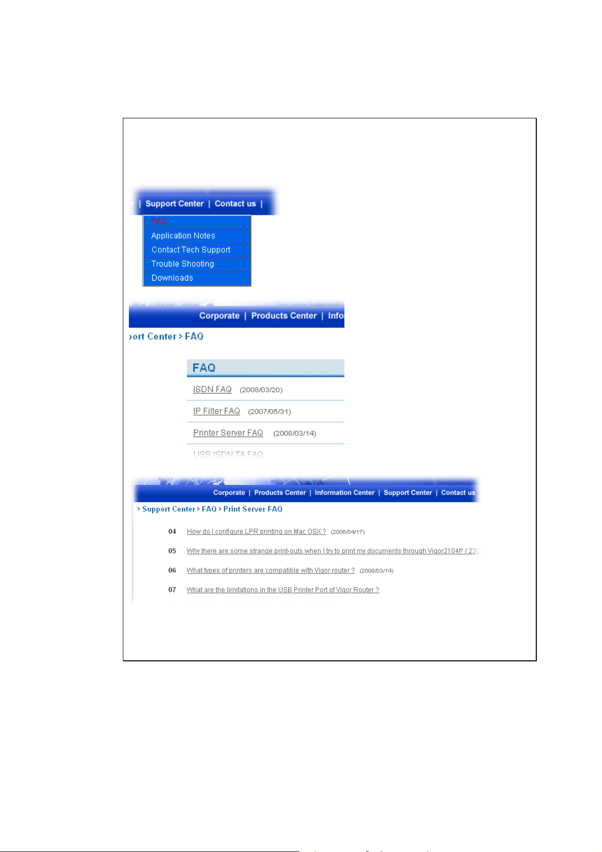
Note 1: Some printers with the fax/scanning or other additional functions are not
supported. If you do not know whether your printer is supported or not, please visit
www.draytek.com to find out the printer list. Open Support Center->FAQ; find out the
link of Printer Server FAQ; finally click the link of “What types of printers are
compatible with Vigor router?”.
Note 2: Vigor router supports printing request from computers via LAN ports but not
WAN port.
14
Vigor2110 Series User’s Guide
2
Coonnffiigguurriinngg
C
For using the router properly, it is necessary for you to change the password of web
configuration for security and adjust primary basic settings.
22..11 TTwwoo--LLeevveell MMaannaaggeemmeenntt
This chapter explains how to setup a password for an administrator/user and how to adjust
basic/advanced settings for accessing Internet successfully.
For user mode operation, do not type any word on the window and click Login for the simple
web pages for configuration. Yet, for admin mode operation, please type “admin/admin” on
Username/Password and click Login for full configuration.
22..22 AAcccceessssiinngg WWeebb PPaaggee
1. Make sure your PC connects to the router correctly.
Notice: You may either simply set up your computer to get IP dynamically
from the router or set up the IP address of the computer to be the same subnet as
the default IP address of Vigor router 192.168.1.1. For the detailed
information, please refer to the later section - Trouble Shooting of the guide.
Baassiicc
B
Seettttiinnggss
S
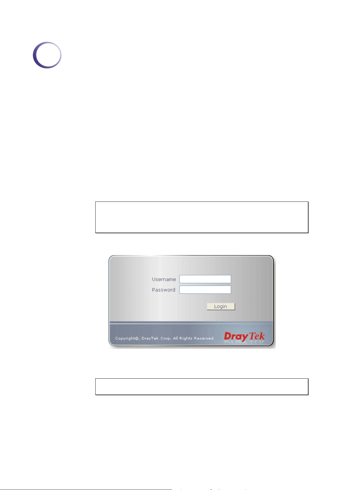
2. Open a web browser on your PC and type http://192.168.1.1. The following window
will be open to ask for username and password.
3. For user mode operation, do not type any word on the window and click Login for the
simple web pages for configuration. Yet, for admin mode operation, please type
“admin/admin” on Username/Password and click Login for full configuration.
Notice: If you fail to access to the web configuration, please go to “Trouble
Shooting” for detecting and solving your problem.
4. The web page can be logged out according to the chosen condition. The default setting is
Auto Logout, which means the web configuration system will logout after 5 minutes
without any operation. Change the setting for your necessity.
Vigor2110 Series User’s Guide
15
22..33 CChhaannggiinngg PPaasssswwoorrdd
No matter user mode operation or admin mode operation, please change the password for the
original security of the router.
1. Open a web browser on your PC and type http://192.168.1.1. A pop-up window will
open to ask for username and password.
2. Please type “admin/admin” on Username/Password for admin mode. Otherwise, do not
type any word (both username and password are Null for user mode) on the window and
click Login on the window.
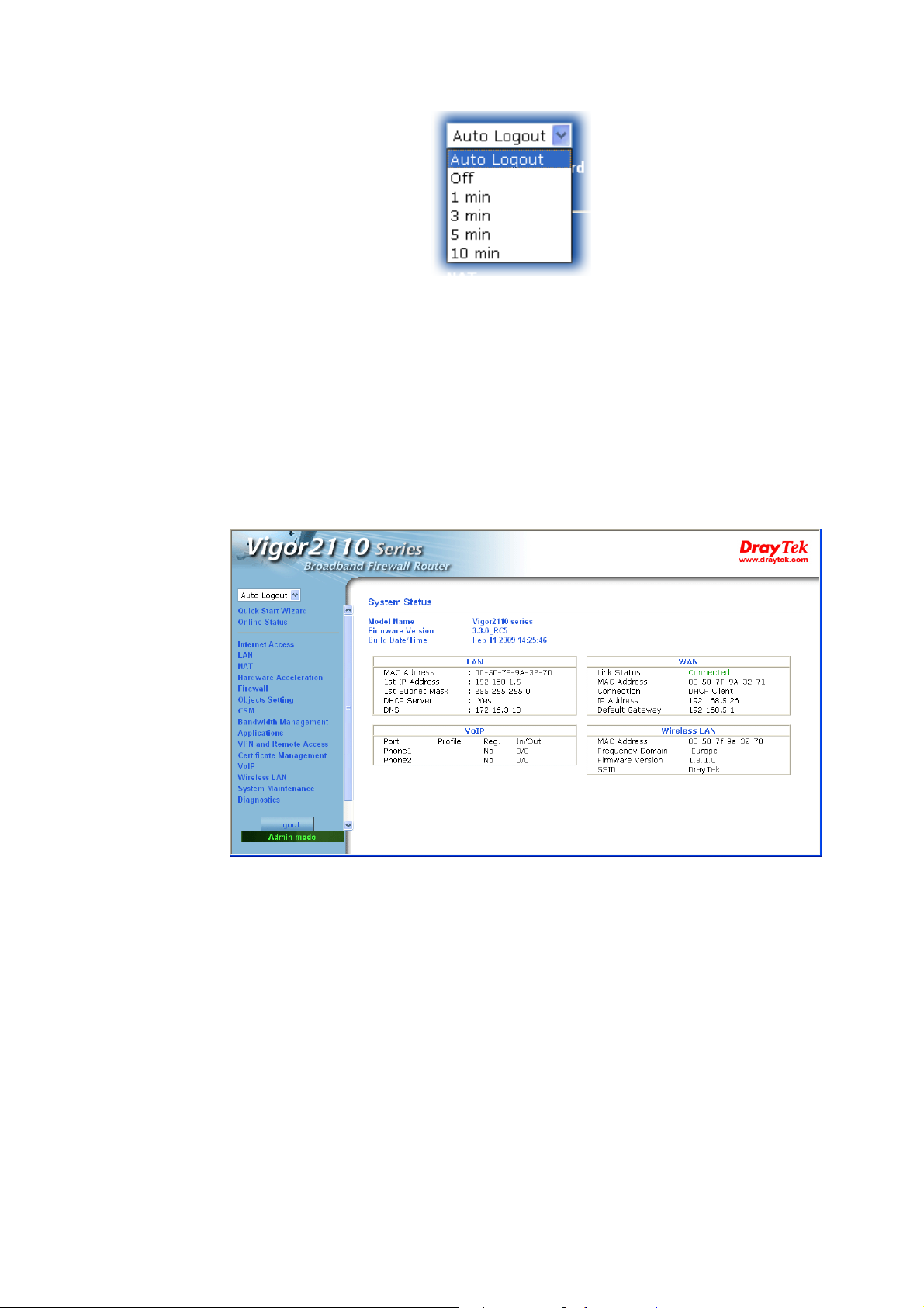
3. Now, the Main Screen will appear.
Main screen for admin mode operation (full configuration)
16
Vigor2110 Series User’s Guide
Main screen for user mode operation (simple configuration)
Note: The home page will change slightly in accordance with the type of the router you
have.
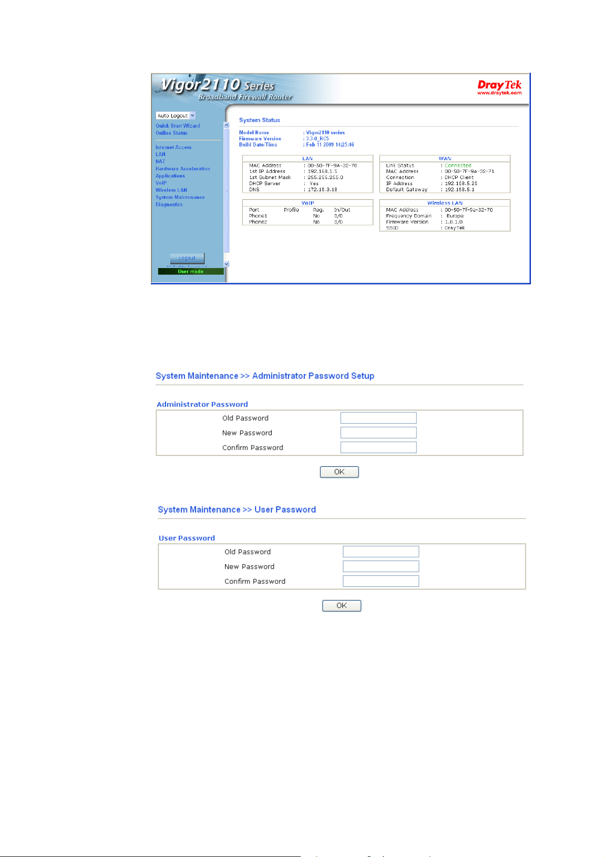
4. Go to System Maintenance page and choose Administrator Password/User
Password.
or
5. Enter the login password (the default is blank) on the field of Old Password. Type New
Password. Then click OK to continue.
6. Now, the password has been changed. Next time, use the new password to access the
Web Configurator for this router.
Vigor2110 Series User’s Guide
17
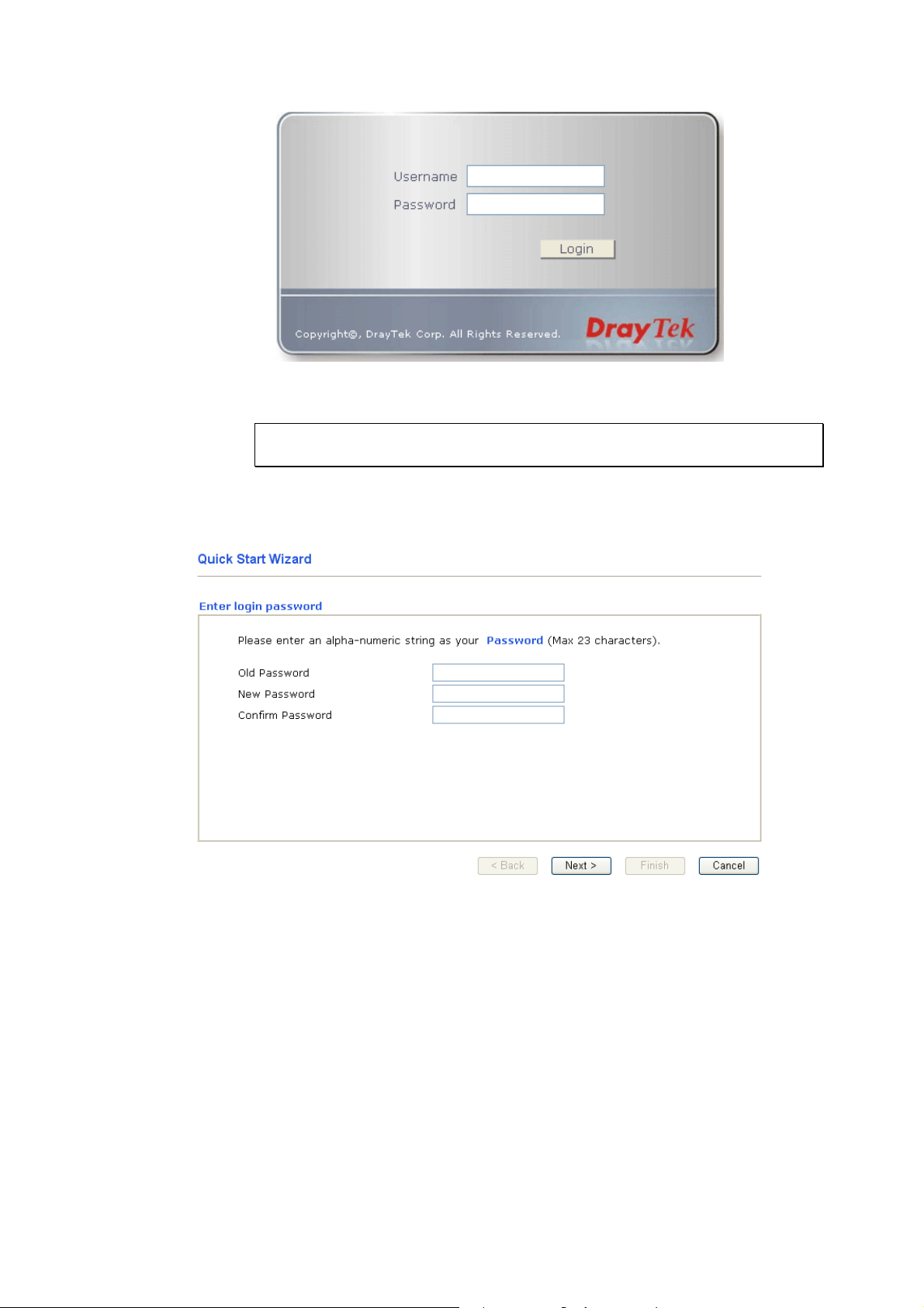
22..44 QQuuiicckk SSttaarrtt WWiizzaarrdd
Notice: Quick Start Wizard for user mode operation is the same as for admin
mode operation.
If your router can be under an environment with high speed NAT, the configuration provide
here can help you to deploy and use the router quickly. The first screen of Quick Start
Wizard is entering login password. After typing the password, please click Next.
On the next page as shown below, please select the appropriate Internet access type according
to the information from your ISP. For example, you should select PPPoE mode if the ISP
provides you PPPoE interface. Then click Next for next step.
18
Vigor2110 Series User’s Guide
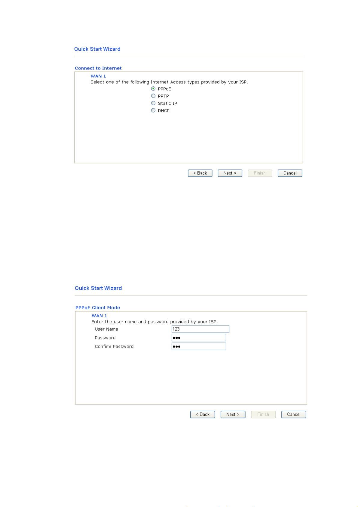
22..44..22 PPPPPPooEE
PPPoE stands for Point-to-Point Protocol over Ethernet. It relies on two widely accepted
standards: PPP and Ethernet. It connects users through an Ethernet to the Internet with a
common broadband medium, such as a single DSL line, wireless device or cable modem. All
the users over the Ethernet can share a common connection.
PPPoE is used for most of DSL modem users. All local users can share one PPPoE connection
for accessing the Internet. Your service provider will provide you information about user name,
password, and authentication mode.
If your ISP provides you the PPPoE connection, please select PPPoE for this router. The
following page will be shown:
User Name Assign a specific valid user name provided by the ISP.
Password Assign a valid password provided by the ISP.
Confirm Password Retype the password.
Vigor2110 Series User’s Guide
19
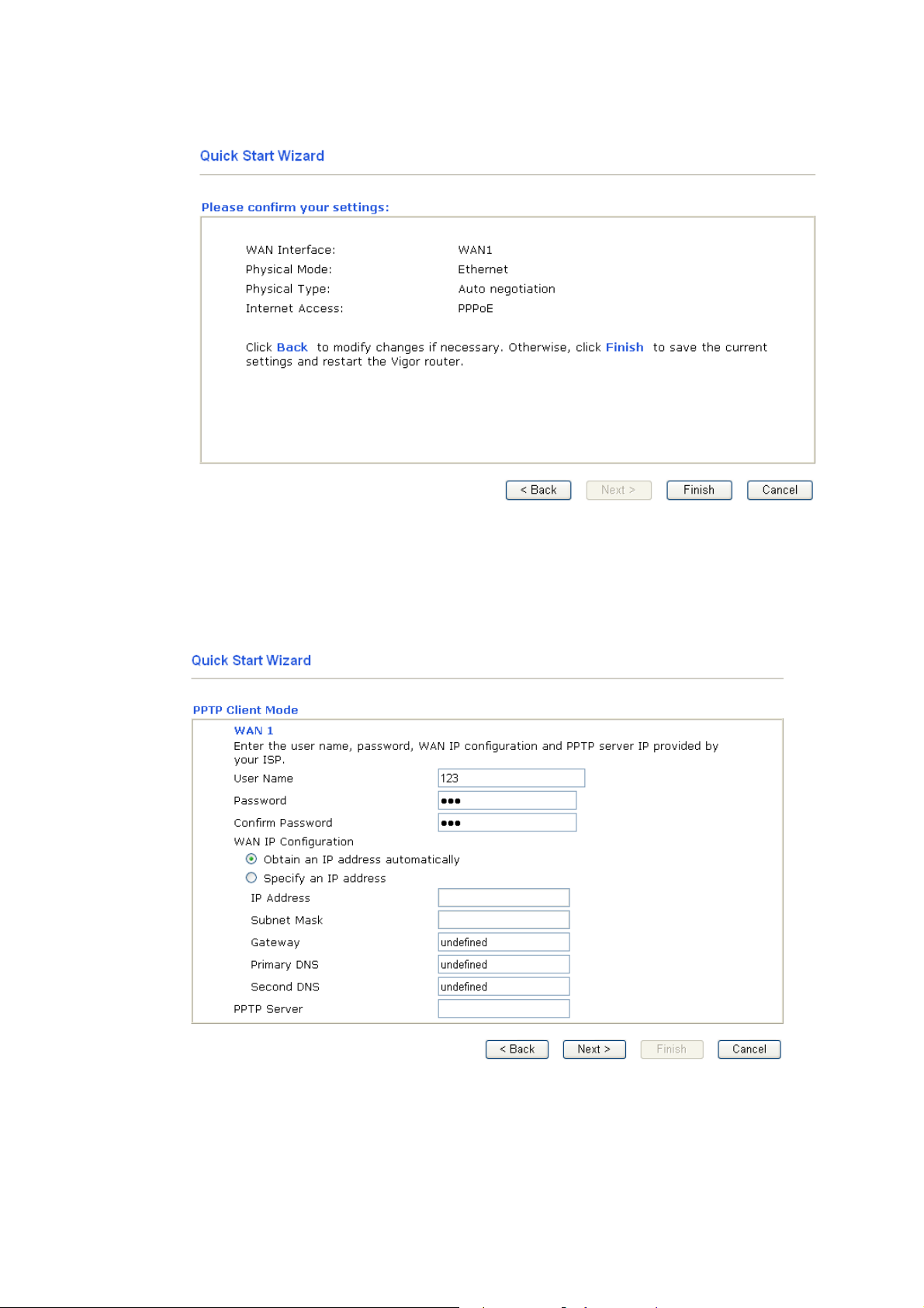
Click Next for viewing summary of such connection.
Click Finish. Then, the system status of this protocol will be shown.
22..44..33 PPPPTTPP
Click PPTP as the protocol. Type in all the information that your ISP provides for this
protocol.
Click Next for viewing summary of such connection.
20
Vigor2110 Series User’s Guide
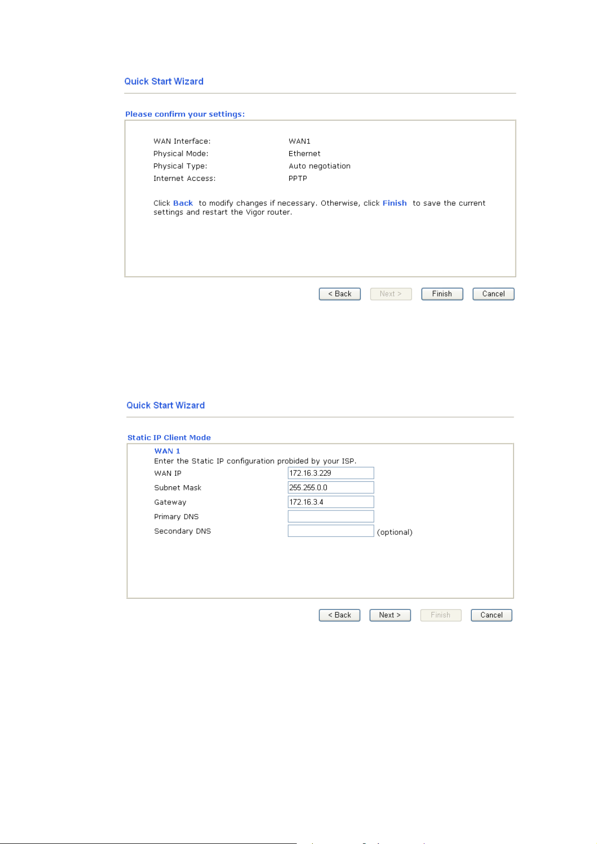
Click Finish. Then, the system status of this protocol will be shown.
22..44..44 SSttaattiicc IIPP
Click Static IP as the protocol. Type in all the information that your ISP provides for this
protocol.
After finishing the settings in this page, click Next to see the following page.
Vigor2110 Series User’s Guide
21
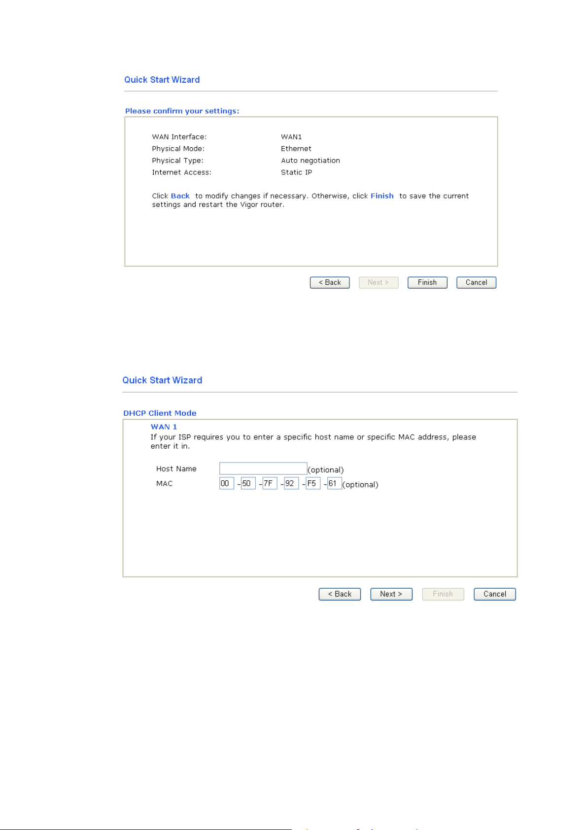
Click Finish. Then, the system status of this protocol will be shown.
22..44..55 DDHHCCPP
Click DHCP as the protocol. Type in all the information that your ISP provides for this
protocol.
After finishing the settings in this page, click Next to see the following page.
22
Vigor2110 Series User’s Guide
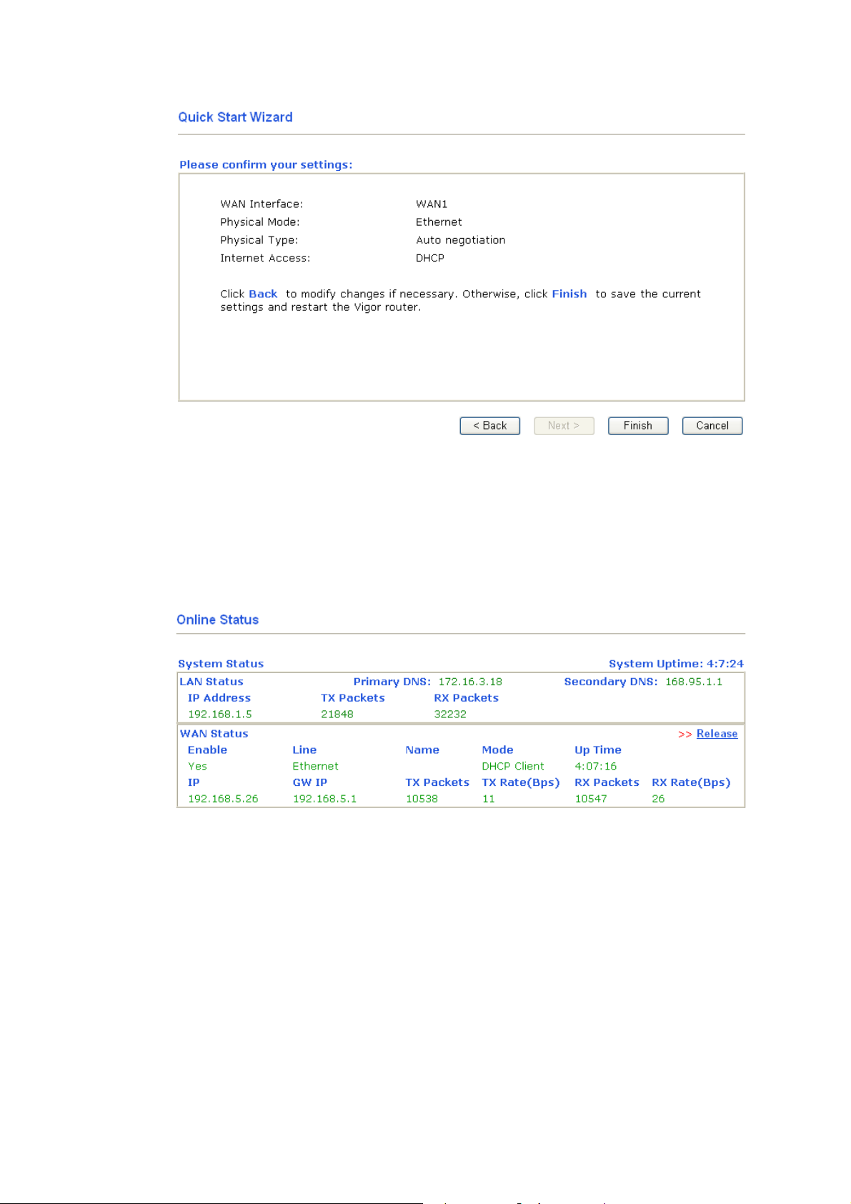
Click Finish. Then, the system status of this protocol will be shown.
22..55 OOnnlliinnee SSttaattuuss
The online status shows the system status, WAN status, and other status related to this router
within one page. If you select PPPoE/PPPoA as the protocol, you will find out a link of Dial
PPPoE or Drop PPPoE in the Online Status web page.
Online status for DHCP
Detailed explanation is shown below:
Primary DNS Displays the IP address of the primary DNS.
Secondary DNS Displays the IP address of the secondary DNS.
LAN Status
IP Address Displays the IP address of the LAN interface.
TX Packets Displays the total transmitted packets at the LAN interface.
RX Packets Displays the total number of received packets at the LAN interface.
WAN Status
Line Displays the physical connection (Ethernet) of this interface.
Vigor2110 Series User’s Guide
23

Name Displays the name set in WAN1/WAN web page.
Mode Displays the type of WAN connection (e.g., PPPoE).
Up Time Displays the total uptime of the interface.
IP Displays the IP address of the WAN interface.
GW IP Displays the IP address of the default gateway.
TX Packets Displays the total transmitted packets at the WAN interface.
TX Rate Displays the speed of transmitted octets at the WAN interface.
RX Packets Displays the total number of received packets at the WAN interface.
RX Rate Displays the speed of received octets at the WAN interface.
Note: The words in green mean that the WAN connection of that interface is ready for
accessing Internet; the words in red mean that the WAN connection of that interface is not
ready for accessing Internet.
22..66 SSaavviinngg CCoonnffiigguurraattiioonn
Each time you click OK on the web page for saving the configuration, you can find messages
showing the system interaction with you.
Ready indicates the system is ready for you to input settings.
Settings Saved means your settings are saved once you click Finish or OK button.
24
Vigor2110 Series User’s Guide

3
Usseerr
U
This chapter will guide users to execute simple configuration through user mode operation. As
for other examples of application, please refer to chapter 5.
1. Open a web browser on your PC and type http://192.168.1.1. The window will ask for
typing username and password.
2. Do not type any word (both username and password are Null for user operation) on the
window and click Login on the window.
Now, the Main Screen will appear. Be aware that “User mode” will be displayed on the
bottom left side.
Mooddee
M
Oppeerraattiioonn
O
33..11 IInntteerrnneett AAcccceessss
Quick Start Wizard offers user an easy method to quick setup the connection mode for the router. Moreover, if you want to adjust more settings for different WAN modes, please go to Internet Access group.
33..11..11 BBaassiiccss ooff IInntteerrnneett PPrroottooccooll ((IIPP)) NNeettwwoorrkk
IP means Internet Protocol. Every device in an IP-based Network including routers, print
server, and host PCs, needs an IP address to identify its location on the network. To avoid
address conflicts, IP addresses are publicly registered with the Network Information Centre
(NIC). Having a unique IP address is mandatory for those devices participated in the public
network but not in the private TCP/IP local area networks (LANs), such as host PCs under the
management of a router since they do not need to be accessed by the public. Hence, the NIC
has reserved certain addresses that will never be registered publicly. These are known as
private IP addresses, and are listed in the following ranges:
Vigor2110 Series User’s Guide
25

From 10.0.0.0 to 10.255.255.255
From 172.16.0.0 to 172.31.255.255
From 192.168.0.0 to 192.168.255.255
WWhhaatt aarree PPuubblliicc IIPP AAddddrreessss aanndd PPrriivvaattee IIPP AAddddrreessss
As the router plays a role to manage and further protect its LAN, it interconnects groups of
host PCs. Each of them has a private IP address assigned by the built-in DHCP server of the
Vigor router. The router itself will also use the default private IP address: 192.168.1.1 to
communicate with the local hosts. Meanwhile, Vigor router will communicate with other
network devices through a public IP address. When the data flow passing through, the
Network Address Translation (NAT) function of the router will dedicate to translate
public/private addresses, and the packets will be delivered to the correct host PC in the local
area network. Thus, all the host PCs can share a common Internet connection.
GGeett YYoouurr PPuubblliicc IIPP AAddddrreessss ffrroomm IISSPP
In ADSL deployment, the PPP (Point to Point)-style authentication and authorization is
required for bridging customer premises equipment (CPE). Point to Point Protocol over
Ethernet (PPPoE) connects a network of hosts via an access device to a remote access
concentrator or aggregation concentrator. This implementation provides users with significant
ease of use. Meanwhile it provides access control, billing, and type of service according to
user requirement.
When a router begins to connect to your ISP, a serial of discovery process will occur to ask for
a connection. Then a session will be created. Your user ID and password is authenticated via
PAP or CHAP with RADIUS authentication system. And your IP address, DNS server, and
other related information will usually be assigned by your ISP.
Below shows the menu items for Internet Access.
33..11..22 PPPPPPooEE
To choose PPPoE as the accessing protocol of the internet, please select PPPoE from the
Internet Access menu. The following web page will be shown.
26
Vigor2110 Series User’s Guide

Enable/Disable Click Enable for activating this function. If you click Disable, this
function will be closed and all the settings that you adjusted in this
page will be invalid.
ISP Access Setup Enter your allocated username, password and authentication
parameters according to the information provided by your ISP.
Username – Type in the username provided by ISP in this field.
Password – Type in the password provided by ISP in this field.
Index (1-15) in Schedule Setup - You can type in four sets of time
schedule for your request. All the schedules can be set previously in
Application – Schedule web page and you can use the number that
you have set in that web page.
WAN Connection
Detection
Such function allows you to verify whether network connection
is alive or not through ARP Detect or Ping Detect.
Mode – Choose ARP Detect or Ping Detect for the system to
execute for WAN detection.
Ping IP – If you choose Ping Detect as detection mode, you have
to type IP address in this field for pinging.
TTL (Time to Live) – Displays value for your reference. TTL
value is set by telnet command.
PPP/MP Setup PPP Authentication – Select PAP only or PAP or CHAP for PPP.
If you want to connect to Internet all the time, you can check
Always On.
Idle Timeout – Set the timeout for breaking down the Internet after
passing through the time without any action.
IP Address
Assignment Method
(IPCP)
Usually ISP dynamically assigns IP address to you each time you
connect to it and request. In some case, your ISP provides service
to always assign you the same IP address whenever you request.
In this case, you can fill in this IP address in the Fixed IP field.
Please contact your ISP before you want to use this function.
Vigor2110 Series User’s Guide
WAN IP Alias - If you have multiple public IP addresses and would
like to utilize them on the WAN interface, please use WAN IP Alias.
27

You can set up to 8 public IP addresses other than the current one
you are using. Notice that this setting is available for WAN1 only.
After finishing all the settings here, please click OK to activate them.
33..11..33 SSttaattiicc oorr DDyynnaammiicc IIPP
For static IP mode, you usually receive a fixed public IP address or a public subnet, namely
multiple public IP addresses from your DSL or Cable ISP service providers. In most cases, a
Cable service provider will offer a fixed public IP, while a DSL service provider will offer a
public subnet. If you have a public subnet, you could assign an IP address or many IP address
to the WAN interface.
To use Static or Dynamic IP as the accessing protocol of the internet, please choose Static or
Dynamic IP mode from Internet Access menu. The following web page will be shown.
Fixed IP – Click Yes to use this function and type in a fixed IP
address in the box of Fixed IP Address.
Default MAC Address – You can use Default MAC Address or
specify another MAC address by typing on the boxes of MAC
Address for the router.
Specify a MAC Address – Type the MAC address for the router
manually.
28
Vigor2110 Series User’s Guide

Access Control
Click Enable for activating this function. If you click Disable,
this function will be closed and all the settings that you adjusted
in this page will be invalid.
Keep WAN
Connection
Normally, this function is designed for Dynamic IP environments
because some ISPs will drop connections if there is no traffic
within certain periods of time. Check Enable PING to keep alive
box to activate this function.
PING to the IP - If you enable the PING function, please specify
the IP address for the system to PING it for keeping alive.
PING Interval - Enter the interval for the system to execute the
PING operation.
WAN Physical Type Choose Auto negotiation as the physical type for your router.
WAN Connection
Detection
Such function allows you to verify whether network connection
is alive or not through ARP Detect or Ping Detect.
Mode – Choose ARP Detect or Ping Detect for the system to
execute for WAN detection.
Ping IP – If you choose Ping Detect as detection mode, you have
to type IP address in this field for pinging.
TTL (Time to Live) – Displays value for your reference. TTL
value is set by telnet command.
RIP Protocol Routing Information Protocol is abbreviated as RIP(RFC1058)
WAN IP Network
Settings
Vigor2110 Series User’s Guide
specifying how routers exchange routing tables information. Click
Enable RIP for activating this function.
This group allows you to obtain an IP address automatically and
allows you type in IP address manually.
29
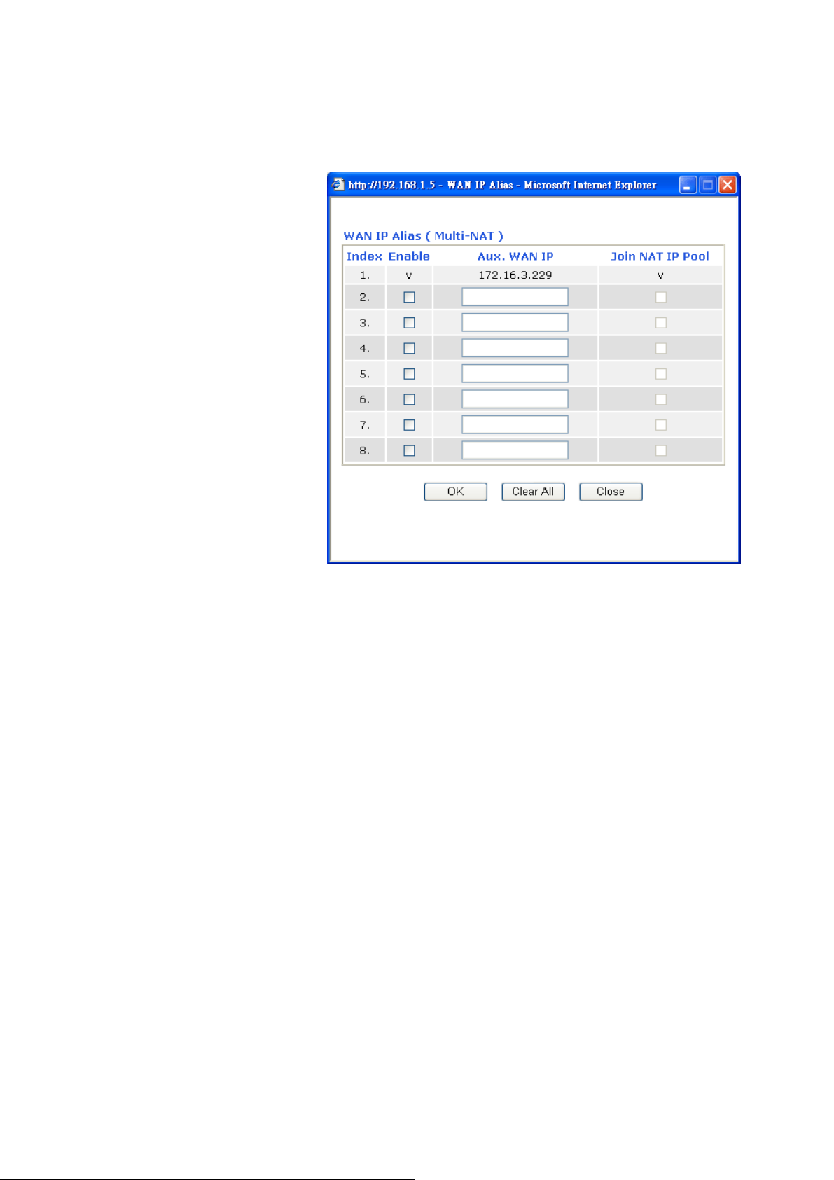
WAN IP Alias - If you have multiple public IP addresses and would
like to utilize them on the WAN interface, please use WAN IP Alias.
You can set up to 8 public IP addresses other than the current one
you are using.
DNS Server IP
Address
33..11..44 PPPPTTPP//LL22TTPP
To use PPTP/L2TP as the accessing protocol of the internet, please choose PPTP/L2TP from
Internet Access menu. The following web page will be shown.
Obtain an IP address automatically – Click this button to obtain
the IP address automatically if you want to use Dynamic IP mode.
Router Name: Type in the router name provided by ISP.
Domain Name: Type in the domain name that you have assigned.
Specify an IP address – Click this radio button to specify some data
if you want to use Static IP mode.
IP Address: Type the IP address.
Subnet Mask: Type the subnet mask.
Gateway IP Address: Type the gateway IP address.
Default MAC Address : Click this radio button to use default MAC
address for the router.
Specify a MAC Address: Some Cable service providers specify a
specific MAC address for access authentication. In such cases you
need to click the Specify a MAC Address and enter the MAC
address in the MAC Address field.
Type in the primary IP address for the router if you want to use
Static IP mode. If necessary, type in secondary IP address for
necessity in the future.
30
Vigor2110 Series User’s Guide

PPTP Setup Enable - Click this radio button to enable a PPTP client to establish
a tunnel to a DSL modem on the WAN interface.
Disable – Click this radio button to close the connection through
PPTP.
PPTP Server - Specify the IP address of the PPTP/L2TP server if
you enable PPTP/L2TP client mode.
ISP Access Setup Username -Type in the username provided by ISP in this field.
Password -Type in the password provided by ISP in this field.
Index (1-15) in Schedule Setup - You can type in four sets of time
schedule for your request. All the schedules can be set previously in
Application – Schedule web page and you can use the number that
you have set in that web page.
PPP Setup PPP Authentication - Select PAP only or PAP or CHAP for PPP.
Idle Timeout - Set the timeout for breaking down the Internet after
passing through the time without any action.
IP Address
Assignment
Method(IPCP)
Fixed IP - Usually ISP dynamically assigns IP address to you each
time you connect to it and request. In some case, your ISP provides
service to always assign you the same IP address whenever you
request. In this case, you can fill in this IP address in the Fixed IP
field. Please contact your ISP before you want to use this function.
Click Yes to use this function and type in a fixed IP address in the
box.
Fixed IP Address -Type a fixed IP address.
WAN IP Network
Settings
Obtain an IP address automatically – Click this button to obtain
the IP address automatically.
Specify an IP address – Click this radio button to specify some data.
IP Address – Type the IP address.
Subnet Mask – Type the subnet mask.
Vigor2110 Series User’s Guide
31

33..22 LLAANN
Local Area Network (LAN) is a group of subnets regulated and ruled by router. The design of
network structure is related to what type of public IP addresses coming from your ISP.
33..22..11 BBaassiiccss ooff LLAANN
The most generic function of Vigor router is NAT. It creates a private subnet of your own. As
mentioned previously, the router will talk to other public hosts on the Internet by using public
IP address and talking to local hosts by using its private IP address. What NAT does is to
translate the packets from public IP address to private IP address to forward the right packets
to the right host and vice versa. Besides, Vigor router has a built-in DHCP server that assigns
private IP address to each local host. See the following diagram for a briefly understanding.
In some special case, you may have a public IP subnet from your ISP such as
220.135.240.0/24. This means that you can set up a public subnet or call second subnet that
each host is equipped with a public IP address. As a part of the public subnet, the Vigor router
will serve for IP routing to help hosts in the public subnet to communicate with other public
hosts or servers outside. Therefore, the router should be set as the gateway for public hosts.
32
Vigor2110 Series User’s Guide

WWhhaatt iiss RRoouuttiinngg IInnffoorrmmaattiioonn PPrroottooccooll ((RRIIPP))
Vigor router will exchange routing information with neighboring routers using the RIP to
accomplish IP routing. This allows users to change the information of the router such as IP
address and the routers will automatically inform for each other.
33..22..22 GGeenneerraall SSeettuupp
This page provides you the general settings for LAN.
Click LAN to open the LAN settings page and choose General Setup.
1st IP Address Type in private IP address for connecting to a local private network
1st Subnet Mask Type in an address code that determines the size of the network.
For IP Routing Usage Click Enable to invoke this function. The default setting is Disable.
Vigor2110 Series User’s Guide
(Default: 192.168.1.1).
(Default: 255.255.255.0/ 24)
33

2nd IP Address Type in secondary IP address for connecting to a subnet.
(Default: 192.168.2.1/ 24)
nd
Subnet Mask An address code that determines the size of the network.
2
(Default: 255.255.255.0/ 24)
nd
DHCP Server You can configure the router to serve as a DHCP server for the 2nd
2
subnet.
Start IP Address: Enter a value of the IP address pool for the DHCP
server to start with when issuing IP addresses. If the 2nd IP address
of your router is 220.135.240.1, the starting IP address must be
220.135.240.2 or greater, but smaller than 220.135.240.254.
IP Pool Counts: Enter the number of IP addresses in the pool. The
maximum is 10. For example, if you type 3 and the 2nd IP address of
your router is 220.135.240.1, the range of IP address by the DHCP
server will be from 220.135.240.2 to 220.135.240.11.
MAC Address: Enter the MAC Address of the host one by one and
click Add to create a list of hosts to be assigned, deleted or edited IP
address from above pool. Set a list of MAC Address for 2
server will help router to assign the correct IP address of the correct
subnet to the correct host. So those hosts in 2
IP address belonging to 1
st
subnet.
nd
subnet won’t get an
nd
DHCP
RIP Protocol Control Disable deactivates the RIP protocol. It will lead to a stoppage of the
exchange of routing information between routers. (Default)
1st Subnet - Select the router to change the RIP information of the
1st subnet with neighboring routers.
2nd Subnet - Select the router to change the RIP information of the
2nd subnet with neighboring routers.
34
Vigor2110 Series User’s Guide

DHCP Server
Configuration
DHCP stands for Dynamic Host Configuration Protocol. The
router by factory default acts a DHCP server for your network so
it automatically dispatch related IP settings to any local user
configured as a DHCP client. It is highly recommended that you
leave the router enabled as a DHCP server if you do not have a
DHCP server for your network.
If you want to use another DHCP server in the network other than
the Vigor Router’s, you can let Relay Agent help you to redirect the
DHCP request to the specified location.
Enable Server - Let the router assign IP address to every host in the
LAN.
Disable Server – Let you manually assign IP address to every host
in the LAN.
Relay Agent – (1
st
subnet/2nd subnet) Specify which subnet that
DHCP server is located the relay agent should redirect the DHCP
request to.
Start IP Address - Enter a value of the IP address pool for the
DHCP server to start with when issuing IP addresses. If the 1st IP
address of your router is 192.168.1.1, the starting IP address must be
192.168.1.2 or greater, but smaller than 192.168.1.254.
IP Pool Counts - Enter the maximum number of PCs that you want
the DHCP server to assign IP addresses to. The default is 50 and the
maximum is 253.
Gateway IP Address - Enter a value of the gateway IP address for
the DHCP server. The value is usually as same as the 1st IP address
of the router, which means the router is the default gateway.
DHCP Server IP Address for Relay Agent - Set the IP address of
the DHCP server you are going to use so the Relay Agent can help to
forward the DHCP request to the DHCP server.
DNS Server
Configuration
DNS stands for Domain Name System. Every Internet host must
have a unique IP address, also they may have a human-friendly,
easy to remember name such as www.yahoo.com. The DNS
server converts the user-friendly name into its equivalent IP
address.
Force DNS manual setting -
in this page instead of DNS servers given by the Internet Access
server (PPPoE, PPTP, L2TP or DHCP server).
Primary IP Address -You must specify a DNS server IP address
here because your ISP should provide you with usually more than
one DNS Server. If your ISP does not provide it, the router will
automatically apply default DNS Server IP address: 194.109.6.66 to
this field.
Secondary IP Address - You can specify secondary DNS server IP
address here because your ISP often provides you more than one
DNS Server. If your ISP does not provide it, the router will
automatically apply default secondary DNS Server IP address:
194.98.0.1 to this field.
The default DNS Server IP address can be found via Online Status:
Force Vigor router to use DNS servers
Vigor2110 Series User’s Guide
35

If both the Primary IP and Secondary IP Address fields are left empty,
the router will assign its own IP address to local users as a DNS
proxy server and maintain a DNS cache.
If the IP address of a domain name is already in the DNS cache, the
router will resolve the domain name immediately. Otherwise, the
router forwards the DNS query packet to the external DNS server by
establishing a WAN (e.g. DSL/Cable) connection.
There are two common scenarios of LAN settings that stated in Chapter 4. For the
configuration examples, please refer to that chapter to get more information for your necessity.
33..33 NNAATT
Usually, the router serves as an NAT (Network Address Translation) router. NAT is a
mechanism that one or more private IP addresses can be mapped into a single public one.
Public IP address is usually assigned by your ISP, for which you may get charged. Private IP
addresses are recognized only among internal hosts.
When the outgoing packets destined to some public server on the Internet reach the NAT
router, the router will change its source address into the public IP address of the router, select
the available public port, and then forward it. At the same time, the router shall list an entry in
a table to memorize this address/port-mapping relationship. When the public server response,
the incoming traffic, of course, is destined to the router’s public IP address and the router will
do the inversion based on its table. Therefore, the internal host can communicate with external
host smoothly.
The benefit of the NAT includes:
z Save cost on applying public IP address and apply efficient usage of IP address.
NAT allows the internal IP addresses of local hosts to be translated into one public IP
address, thus you can have only one IP address on behalf of the entire internal hosts.
z Enhance security of the internal network by obscuring the IP address. There are
many attacks aiming victims based on the IP address. Since the attacker cannot be aware
of any private IP addresses, the NAT function can protect the internal network.
On NAT page, you will see the private IP address defined in RFC-1918. Usually we use the
192.168.1.0/24 subnet for the router. As stated before, the NAT facility can map one or
more IP addresses and/or service ports into different specified services. In other words, the
NAT function can be achieved by using port mapping methods.
Below shows the menu items for NAT.
33..33..11 PPoorrtt RReeddiirreeccttiioonn
Port Redirection is usually set up for server related service inside the local network (LAN),
such as web servers, FTP servers, E-mail servers etc. Most of the case, you need a public IP
address for each server and this public IP address/domain name are recognized by all users.
Since the server is actually located inside the LAN, the network well protected by NAT of the
router, and identified by its private IP address/port, the goal of Port Redirection function is to
forward all access request with public IP address from external users to the mapping private IP
address/port of the server.
36
Vigor2110 Series User’s Guide

The port redirection can only apply to incoming traffic.
To use this function, please go to NAT page and choose Port Redirection web page. The
Port Redirection Table provides 20 port-mapping entries for the internal hosts.
Press any number under Index to access into next page for configuring port redirection.
Vigor2110 Series User’s Guide
37

Enable Check this box to enable such port redirection setting.
Mode Two options (Single and Range) are provided here for you to choose.
To set a range for the specific service, select Range. In Range mode,
if the public port (start port and end port) and the starting IP of
private IP had been entered, the system will calculate and display the
ending IP of private IP automatically.
Service Name Enter the description of the specific network service.
Protocol Select the transport layer protocol (TCP or UDP).
WAN IP Select the WAN IP used for port redirection. There are eight WAN
IP alias that can be selected and used for port redirection. The
default setting is All which means all the incoming data from any
port will be redirected to specified range of IP address and port.
Public Port Specify which port can be redirected to the specified Private IP and
Port of the internal host. If you choose Range as the port redirection
mode, you will see two boxes on this field. Simply type the required
number on the first box. The second one will be assigned
automatically later.
Private IP Specify the private IP address of the internal host providing the
service. If you choose Range as the port redirection mode, you will
see two boxes on this field. Type a complete IP address in the first
box (as the starting point) and the fourth digits in the second box (as
the end point).
Private Port Specify the private port number of the service offered by the internal
host.
Note that the router has its own built-in services (servers) such as Telnet, HTTP and FTP etc.
Since the common port numbers of these services (servers) are all the same, you may need to
reset the router in order to avoid confliction.
33..33..22 DDMMZZ HHoosstt
As mentioned above, Port Redirection can redirect incoming TCP/UDP or other traffic on
particular ports to the specific private IP address/port of host in the LAN. However, other IP
protocols, for example Protocols 50 (ESP) and 51 (AH), do not travel on a fixed port. Vigor
router provides a facility DMZ Host that maps ALL unsolicited data on any protocol to a
38
Vigor2110 Series User’s Guide

single host in the LAN. Regular web surfing and other such Internet activities from other
clients will continue to work without inappropriate interruption. DMZ Host allows a defined
internal user to be totally exposed to the Internet, which usually helps some special
applications such as Netmeeting or Internet Games etc.
The security properties of NAT are somewhat bypassed if you set up DMZ host. We suggest
you to add additional filter rules or a secondary firewall.
Click DMZ Host to open the following page:
If you previously have set up WAN Alias for PPPoE or Static or Dynamic IP mode, you will
find them in Aux. WAN IP for your selection.
Vigor2110 Series User’s Guide
39

Enable Check to enable the DMZ Host function.
Private IP Enter the private IP address of the DMZ host, or click Choose PC to
select one.
Choose PC Click this button and then a window will automatically pop up, as
depicted below. The window consists of a list of private IP addresses
of all hosts in your LAN network. Select one private IP address in
the list to be the DMZ host.
When you have selected one private IP from the above dialog, the IP
address will be shown on the following screen. Click OK to save the
setting.
40
Vigor2110 Series User’s Guide

33..33..33 OOppeenn PPoorrttss
Open Ports allows you to open a range of ports for the traffic of special applications.
Common application of Open Ports includes P2P application (e.g., BT, KaZaA, Gnutella,
WinMX, eMule and others), Internet Camera etc. Ensure that you keep the application
involved up-to-date to avoid falling victim to any security exploits.
Click Open Ports to open the following page:
Index Indicate the relative number for the particular entry that you want to
offer service in a local host. You should click the appropriate index
number to edit or clear the corresponding entry.
Comment Specify the name for the defined network service.
Local IP Address Display the private IP address of the local host offering the service.
Status Display the state for the corresponding entry. X or V is to represent
the Inactive or Active state.
To add or edit port settings, click one index number on the page. The index entry setup page
will pop up. In each index entry, you can specify 10 port ranges for diverse services.
Vigor2110 Series User’s Guide
41

Enable Open Ports Check to enable this entry.
Comment Make a name for the defined network application/service.
WAN IP Specify the WAN IP address that will be used for this entry. This
Local Computer Enter the private IP address of the local host or click Choose PC to
Choose PC Click this button and, subsequently, a window having a list of
Protocol Specify the transport layer protocol. It could be TCP, UDP, or -----
Start Port Specify the starting port number of the service offered by the local
End Port Specify the ending port number of the service offered by the local
33..44 AApppplliiccaattiioonnss
Below shows the menu items for Applications.
setting is available when WAN IP Alias is configured.
select one.
private IP addresses of local hosts will automatically pop up. Select
the appropriate IP address of the local host in the list.
(none) for selection.
host.
host.
33..44..11 DDyynnaammiicc DDNNSS
The ISP often provides you with a dynamic IP address when you connect to the Internet via
your ISP. It means that the public IP address assigned to your router changes each time you
access the Internet. The Dynamic DNS feature lets you assign a domain name to a dynamic
WAN IP address. It allows the router to update its online WAN IP address mappings on the
specified Dynamic DNS server. Once the router is online, you will be able to use the
42
Vigor2110 Series User’s Guide

registered domain name to access the router or internal virtual servers from the Internet. It is
particularly helpful if you host a web server, FTP server, or other server behind the router.
Before you use the Dynamic DNS feature, you have to apply for free DDNS service to the
DDNS service providers. The router provides up to three accounts from three different DDNS
service providers. Basically, Vigor routers are compatible with the DDNS services supplied by
most popular DDNS service providers such as www.dyndns.org, www.no-ip.com,
www.dtdns.com, www.changeip.com, www.dynamic- nameserver.com. You should visit
their websites to register your own domain name for the router.
Enable the Function and Add a Dynamic DNS Account
1. Assume you have a registered domain name from the DDNS provider, say
hostname.dyndns.org, and an account with username: test and password: test.
2. In the DDNS setup menu, check Enable Dynamic DNS Setup.
Set to Factory Default Clear all profiles and recover to factory settings.
Enable Dynamic DNS Setup Check this box to enable DDNS function.
Index Click the number below Index to access into the setting
page of DDNS setup to set account(s).
Domain Name Display the domain name that you set on the setting page
of DDNS setup.
Active Display if this account is active or inactive.
View Log Display DDNS log status.
Force Update Force the router updates its information to DDNS server.
3. Select Index number 1 to add an account for the router. Check Enable Dynamic DNS
Account, and choose correct Service Provider: dyndns.org, type the registered hostname:
hostname and domain name suffix: dyndns.org in the Domain Name block. The
following two blocks should be typed your account Login Name: test and Password: test.
Vigor2110 Series User’s Guide
43

Enable Dynamic
DNS Account
Check this box to enable the current account. If you did
check the box, you will see a check mark appeared on the
Active column of the previous web page in step 2).
Service Provider Select the service provider for the DDNS account.
4. Click OK button to activate the settings. You will see your setting has been saved.
The Wildcard and Backup MX features are not supported for all Dynamic DNS providers. You
could get more detailed information from their websites.
Disable the Function and Clear all Dynamic DNS Accounts
In the DDNS setup menu, uncheck Enable Dynamic DNS Setup, and push Clear All button
to disable the function and clear all accounts from the router.
Delete a Dynamic DNS Account
In the DDNS setup menu, click the Index number you want to delete and then push Clear All
button to delete the account.
33..44..22 UUPPnnPP
The UPnP (Universal Plug and Play) protocol is supported to bring to network connected
devices the ease of installation and configuration which is already available for directly
connected PC peripherals with the existing Windows 'Plug and Play' system. For NAT routers,
the major feature of UPnP on the router is “NAT Traversal”. This enables applications inside
the firewall to automatically open the ports that they need to pass through a router. It is more
reliable than requiring a router to work out by itself which ports need to be opened. Further,
the user does not have to manually set up port mappings or a DMZ. UPnP is available on
Windows XP and the router provide the associated support for MSN Messenger to allow full
use of the voice, video and messaging features.
Service Type Select a service type (Dynamic, Custom or Static). If you
choose Custom, you can modify the domain that is chosen in
the Domain Name field.
Domain Name Type in one domain name that you applied previously. Use the
drop down list to choose the desired domain.
Login Name Type in the login name that you set for applying domain.
Password Type in the password that you set for applying domain.
44
Vigor2110 Series User’s Guide

Enable UPNP Service Accordingly, you can enable either the Connection Control
Service or Connection Status Service.
After setting Enable UPNP Service setting, an icon of IP Broadband Connection on Router
on Windows XP/Network Connections will appear. The connection status and control status
will be able to be activated. The NAT Traversal of UPnP enables the multimedia features of
your applications to operate. This has to manually set up port mappings or use other similar
methods. The screenshots below show examples of this facility.
The UPnP facility on the router enables UPnP aware applications such as MSN Messenger to
discover what are behind a NAT router. The application will also learn the external IP address
and configure port mappings on the router. Subsequently, such a facility forwards packets from
the external ports of the router to the internal ports used by the application.
Vigor2110 Series User’s Guide
45

The reminder as regards concern about Firewall and UPnP
Can't work with Firewall Software
Enabling firewall applications on your PC may cause the UPnP function not working
properly. This is because these applications will block the accessing ability of some network
ports.
33..55 VVooIIPP
Security Considerations
Activating the UPnP function on your network may incur some security threats. You should
consider carefully these risks before activating the UPnP function.
¾ Some Microsoft operating systems have found out the UPnP weaknesses and hence
you need to ensure that you have applied the latest service packs and patches.
¾ Non-privileged users can control some router functions, including removing and
adding port mappings.
The UPnP function dynamically adds port mappings on behalf of some UPnP-aware
applications. When the applications terminate abnormally, these mappings may not be
removed.
Voice over IP network (VoIP) enables you to use your broadband Internet connection to make
toll quality voice calls over the Internet.
There are many different call signaling protocols, methods by which VoIP devices can talk to
each other. The most popular protocols are SIP, MGCP, Megaco and H.323. These protocols
are not all compatible with each other (except via a soft-switch server).
The Vigor V models support the SIP protocol as this is an ideal and convenient deployment
for the ITSP (Internet Telephony Service Provider) and softphone and is widely supported.
SIP is an end-to-end, signaling protocol that establishes user presence and mobility in VoIP
structure. Every one who wants to talk using his/her SIP Uniform Resource Identifier, “SIP
Address”. The standard format of SIP URI is
sip: user:password @ host: port
Some fields may be optional in different use. In general, "host” refers to a domain. The
“userinfo” includes the user field, the password field and the @ sign following them. This is
very similar to a URL so some may call it “SIP URL”. SIP supports peer-to-peer direct calling
and also calling via a SIP proxy server (a role similar to the gatekeeper in H.323 networks),
46
Vigor2110 Series User’s Guide
while the MGCP protocol uses client-server architecture, the calling scenario being very
similar to the current PSTN/ISDN network.
After a call is setup, the voice streams transmit via RTP (Real-Time Transport Protocol).
Different codecs (methods to compress and encode the voice) can be embedded into RTP
packets. Vigor V models provide various codecs, including G.711 A/µ-law, G.723, G.726 and
G.729 A & B. Each codec uses a different bandwidth and hence provides different levels of
voice quality. The more bandwidth a codec uses the better the voice quality, however the
codec used must be appropriate for your Internet bandwidth.
Usually there will be two types of calling scenario, as illustrated below:
z Calling via SIP Servers
First, the Vigor V models of yours will have to register to a SIP Registrar by sending
registration messages to validate. Then, both parties’ SIP proxies will forward the
sequence of messages to caller to establish the session.
If you both register to the same SIP Registrar, then it will be illustrated as below:
The major benefit of this mode is that you don’t have to memorize your friend’s IP
address, which might change very frequently if it’s dynamic. Instead of that, you will
only have to using dial plan or directly dial your friend’s account name if you are with
the same SIP Registrar.
z Peer-to-Peer
Before calling, you have to know your friend’s IP Address. The Vigor VoIP Routers will
build connection between each other.
Vigor2110 Series User’s Guide
47

Our Vigor V models firstly apply efficient codecs designed to make the best use of
available bandwidth, but Vigor V models also equip with automatic QoS assurance.
QoS Assurance assists to assign high priority to voice traffic via Internet. You will
always have the required inbound and outbound bandwidth that is prioritized exclusively
for Voice traffic over Internet but you just get your data a little slower and it is tolerable
for data traffic.
33..55..11 DDiiaallPPllaann
This page allows you to set phone book and digit map for the VoIP function. Click the Phone
Book and Digit Map links on the page to access into next pages for dialplan settings.
PPhhoonnee BBooookk
In this section, you can set your VoIP contacts in the “phonebook”. It can help you to make
calls quickly and easily by using “speed-dial” Phone Number. There are total 60 index entries
in the phonebook for you to store all your friends and family members’ SIP addresses. Loop
through and Backup Phone Number will be displayed if you are using Vigor 2820V for
setting the phone book.
48
Vigor2110 Series User’s Guide

Click any index number to display the dial plan setup page.
Enable Click this to enable this entry.
Phone Number The speed-dial number of this index. This can be any number
you choose, using digits 0-9 and * .
Display Name The Caller-ID that you want to be displayed on your friend’s
screen. This let your friend can easily know who’s calling
without memorizing lots of SIP URL Address.
SIP URL Enter your friend’s SIP Address.
Dial Out Account Choose one of the SIP accounts for this profile to dial out. It is
Vigor2110 Series User’s Guide
useful for both sides (caller and callee) that registered to
different SIP Registrar servers. If caller and callee do not use
49

the same SIP server, sometimes, the VoIP phone call
connection may not succeed. By using the specified dial out
account, the successful connection can be assured.
Loop through The selection should be as the following:
Backup Phone Number When the VoIP phone is obstructs or the Internet breaks down
for some reasons, the backup phone will be dialed out to replace
the VoIP phone number. At this time, the phone call will be
changed from VoIP phone into PSTN call according to the loop
through direction chosen. Note that, during the phone switch,
the blare of phone will appear for a short time. And when the
VoIP phone is switched into the PSTN phone, the telecom co.
might charge you for the connection fee. Please type in backup
phone number (PSTN) for this VoIP phone setting.
DDiiggiitt MMaapp
For the convenience of user, this page allows users to edit prefix number for the SIP account
with adding number, stripping number or replacing number. It is used to help user having a
quick and easy way to dial out through VoIP interface.
50
Vigor2110 Series User’s Guide

Enable Check this box to invoke this setting.
Prefix Number The phone number set here is used to add, strip, or replace the
OP number.
Mode None - No action.
Add - When you choose this mode, the OP number will be
added with the prefix number for calling out through the
specific VoIP interface.
Strip - When you choose this mode, the OP number will be
deleted by the prefix number for calling out through the specific
VoIP interface. Take the above picture (Prefix Table Setup web
page) as an example, the OP number of 886 will be deleted
completely for the prefix number is set with 886.
Replace - When you choose this mode, the OP number will be
replaced by the prefix number for calling out through the
specific VoIP interface. Take the above picture (Prefix Table
Setup web page) as an example, the prefix number of 03 will be
replaced by 8863. For example: dial number of “031111111”
Vigor2110 Series User’s Guide
51

will be changed to “88631111111” and sent to SIP server.
OP Number The front number you type here is the first part of the account
number that you want to execute special function (according to
the chosen mode) by using the prefix number.
Min Len Set the minimal length of the dial number for applying the
prefix number settings. Take the above picture (Prefix Table
Setup web page) as an example, if the dial number is between 7
and 9, that number can apply the prefix number settings here.
Max Len Set the maximum length of the dial number for applying the
prefix number settings.
Interface Choose the one that you want to enable the prefix number
settings from the saved SIP accounts. Please set up one SIP
account first to make this interface available.
CCaallll BBaarrrriinngg
Call barring is used to block phone calls coming from the one that is not welcomed.
Click any index number to display the dial plan setup page.
52
Vigor2110 Series User’s Guide

Enable Click this to enable this entry.
Call Direction Determine the direction for the phone call, IN – incoming call,
OUT-outgoing call, IN & OUT – both incoming and outgoing
calls.
Barring Type Determine the type of the VoIP phone call, URI/URL or
number.
Specific URI/URL or
Specific Number
This field will be changed based on the type you selected for
barring Type.
Interface All means all the phone calls will be blocked with such
mechanism.
Index (1-15) in Schedule Enter the index of schedule profiles to control the call barring
according to the preconfigured schedules. Refer to section 3.5.2
Schedule for detailed configuration.
Additionally, you can set advanced settings for call barring such as Block Anonymous, Block
Unknown Domain or Block IP Address. Simply click the relational links to open the web
page.
For Block Anonymous – this function can block the incoming calls without caller ID on the
interface (Phone port) specified in the following window. Such control also can be done based
on preconfigured schedules.
Vigor2110 Series User’s Guide
53

For Block Unknown Domain – this function can block incoming calls (through Phone port)
from unrecognized domain that is not specified in SIP accounts. Such control also can be done
based on preconfigured schedules.
For Block IP Address – this function can block incoming calls (through Phone port) coming
from IP address. Such control also can be done based on preconfigured schedules.
RReeggiioonnaall
This page allows you to process incoming or outgoing phone calls by regional. Default values
(common used in most areas) will be shown on this web page. You can change the number
based on the region that the router is placed.
54
Vigor2110 Series User’s Guide

Last Call Return [Miss] Sometimes, people might miss some phone calls. Please dial
number typed in this field to know where the last phone call
comes from and call back to that one.
Last Call Return [In] You have finished an incoming phone call, however you want
to call back again for some reason. Please dial number typed in
this field to call back to that one.
Last Call Return [Out] Dial the number typed in this field to call the previous outgoing
phone call again.
Call Forward [All][Act] Dial the number typed in this field to forward all the incoming
calls to the specified place.
Call Forward [Deact] Dial the number typed in this field to release the call forward
function.
Call Forward [Busy][Act] Dial the number typed in this field to forward all the incoming
calls to the specified place while the phone is busy.
Call Forward [No Ans][Act] Dial the number typed in this field to forward all the incoming
calls to the specified place while there is no answer of the
connected phone.
Do Not Disturb [Act] Dial the number typed in this field to invoke the function of
Do Not Distrub [Deact] Dial the number typed in this field to release the DN D function.
Hide caller ID [Act] Dial the number typed in this field to make your phone number
Hide caller ID [Deact] Dial the number typed in this field to release this function.
Vigor2110 Series User’s Guide
DND.
(ID) not displayed on the display panel of remote end.
55

Call Waiting [Act] Dial the number typed in this field to make all the incoming
calls waiting for your answer.
Call Waiting [Deact] Dial the number typed in this field to release this function.
Block Anonymous[Act] Dial the number typed in this field to block all the incoming
calls with unknown ID.
Block Anonymous[Deact] Dial the number typed in this field to release this function.
Block Unknown Domain
[Act]
Block Unknown Domain
[Deact]
Block IP Calls [Act] Dial the number typed in this field to block all the incoming
Block IP Calls [Deact] Dial the number typed in this field to release this function.
Block Last Calls [Act] Dial the number typed in this field to block the last incoming
PPSSTTNN SSeettuupp
Some emergency phone (e.g., 911) or special phone cannot be dialed out by using VoIP and
can be called out through PSTN line only. To solve this problem, this page allows you to set
five sets of PSTN number for dialing without passing through Internet. Please type the number
in the field of phone number for PSTN relay.
Dial the number typed in this field to block all the incoming
calls from unknown domain.
Dial the number typed in this field to release this function.
calls from IP address.
phone call.
Then, check the Enable box to make the PSTN number available for dial whenever you need.
33..55..22 SSIIPP AAccccoouunnttss
In this section, you set up your own SIP settings. When you apply for an account, your SIP
service provider will give you an Account Name or user name, SIP Registrar, Proxy, and
Domain name. (The last three might be the same in some case). Then you can tell your folks
your SIP Address as in Account Name@ Domain name
56
Vigor2110 Series User’s Guide

As Vigor VoIP Router is turned on, it will first register with Registrar using
AuthorizationUser@Domain/Realm. After that, your call will be bypassed by SIP Proxy to the
destination using AccountName@Domain/Realm as identity.
Index Click this link to access into next page for setting SIP account.
Profile Display the profile name of the account.
Domain/Realm Display the domain name or IP address of the SIP registrar
server.
Proxy Display the domain name or IP address of the SIP proxy server.
Account Name Display the account name of SIP address before @.
Ring Port Specify which port will ring when receiving a phone call.
STUN Server Type in the IP address or domain of the STUN server.
External IP Type in the gateway IP address.
SIP PING interval The default value is 150 (sec). It is useful for a Nortel server
NAT Traversal Support.
Status Show the status for the corresponding SIP account. R means
such account is registered on SIP server successfully. – means
the account is failed to register on SIP server.
Vigor2110 Series User’s Guide
57

Profile Name Assign a name for this profile for identifying. You can type
similar name with the domain. For example, if the domain name
is draytel.org, then you might set draytel-1 in this field.
Register via If you want to make VoIP call without register personal
information, please choose None and check the box to achieve
the goal. Some SIP server allows user to use VoIP function
without registering. For such server, please check the box of
Call without registration. Choosing Auto is recommended.
SIP Port Set the port number for sending/receiving SIP message for
building a session. The default value is 5060. Your peer must
set the same value in his/her Registrar.
Domain/Realm Set the domain name or IP address of the SIP Registrar server.
Proxy Set domain name or IP address of SIP proxy server. By the time
you can type :port number after the domain name to specify
that port as the destination of data transmission (e.g.,
nat.draytel.org:5065)
Act as Outbound Proxy Check this box to make the proxy acting as outbound proxy.
Display Name The caller-ID that you want to be displayed on your friend’s
screen.
Account Number/Name Enter your account name of SIP Address, e.g. every text before
@.
Authentication ID Check the box to invoke this function and enter the name or
number used for SIP Authorization with SIP Registrar. If this
58
Vigor2110 Series User’s Guide

setting value is the same as Account Name, it is not necessary
for you to check the box and set any value in this field.
Password The password provided to you when you registered with a SIP
service.
Expiry Time The time duration that your SIP Registrar server keeps your
registration record. Before the time expires, the router will send
another register request to SIP Registrar again.
NAT Traversal Support If the router (e.g., broadband router) you use connects to
internet by other device, you have to set this function for your
necessity.
None – Disable this function.
Stun – Choose this option if there is Stun server provided for
your router.
Manual – Choose this option if you want to specify an external
IP address as the NAT transversal support.
Nortel – If the soft-switch that you use supports Nortel solution,
you can choose this option.
Ring Port Set Phone1 or Phone2 as the default ring port for this SIP
Ring Pattern Choose a ring tone type for the VoIP phone call.
33..55..33 PPhhoonnee SSeettttiinnggss
This page allows user to set phone settings for Phone 1 and Phone 2 respectively. However, it
changes slightly according to different model you have.
account.
Vigor2110 Series User’s Guide
59

60
Vigor2110 Series User’s Guide

Phone List Port – there are two phone ports provided here for you to
configure. Phone1/Phone2 allow you to set general settings for
PSTN phones.
Call Feature – A brief description for call feature will be
shown in this field for your reference.
Codec – The default Codec setting for each port will be shown
in this field for your reference. You can click the number below
the Index field to change it for each phone port.
Tone - Display the tone settings that configured in the advanced
settings page of Phone Index.
Gain - Display the volume gain settings for Mic/Speaker that
configured in the advanced settings page of Phone Index.
Default SIP Account – “draytel_1” is the default SIP account.
You can click the number below the Index field to change SIP
account for each phone port.
DTMF Relay – Display DTMF mode that configured in the
advanced settings page of Phone Index.
RTP Symmetric RTP – Check this box to invoke the function. To
make the data transmission going through on both ends of local
router and remote router not misleading due to IP lost (for
example, sending data from the public IP of remote router to the
private IP of local router), you can check this box to solve this
problem.
Dynamic RTP Port Start - Specifies the start port for RTP
stream. The default value is 10050.
Dynamic RTP Port End - Specifies the end port for RTP
stream. The default value is 15000.
RTP TOS – It decides the level of VoIP package. Use the drop
down list to choose any one of them.
DDeettaaiilleedd SSeettttiinnggss ffoorr PPhhoonnee PPoorrtt
Click the number link for Phone port, you can access into the following page for configuring
Phone settings.
Vigor2110 Series User’s Guide
61

Hotline Check the box to enable it. Type in the SIP URL in the field for
dialing automatically when you pick up the phone set.
Session Timer Check the box to enable the function. In the limited time that
you set in this field, if there is no response, the connecting call
will be closed automatically.
Call Forwarding There are four options for you to choose. Disable is to close call
forwarding function. Always means all the incoming calls will
be forwarded into SIP URL without any reason. Busy means
the incoming calls will be forwarded into SIP URL only when
the local system is busy. No Answer means if the incoming
calls do not receive any response, they will be forwarded to the
SIP URL by the time out.
SIP URL – Type in the SIP URL (e.g., aaa@draytel.org or
abc@iptel.org) as the site for call forwarded.
Time Out – Set the time out for the call forwarding. The
default setting is 30 sec.
DND (Do Not Disturb)
mode
Set a period of peace time without disturbing by VoIP phone
call. During the period, the one who dial in will listen busy
tone, yet the local user will not listen any ring tone.
Index (1-15) in Schedule - Enter the index of schedule profiles
to control the DND mode according to the preconfigured
schedules. Refer to section 3.8.2 Schedule for detailed
configuration.
Index (1-60) in Phone Book - Enter the index of phone book
62
Vigor2110 Series User’s Guide

profiles. Refer to section VoIP>>DialPlan>>Phone Book for
detailed configuration.
CLIR (hide caller ID) Check this box to hide the caller ID on the display panel of the
phone set.
Call Waiting Check this box to invoke this function. A notice sound will
appear to tell the user new phone call is waiting for your
response. Click hook flash to pick up the waiting phone call.
Call Transfer Check this box to invoke this function. Click hook flash to
initiate another phone call. When the phone call connection
succeeds, hang up the phone. The other two sides can
communicate, then.
Prefer Codec Select one of five codecs as the default for your VoIP calls. The
codec used for each call will be negotiated with the peer party
before each session, and so may not be your default choice. The
default codec is G.729A/B; it occupies little bandwidth while
maintaining good voice quality.
If your upstream speed is only 64Kbps, do not use G.711 codec.
It is better for you to have at least 256Kbps upstream if you
would like to use G.711.
Single Codec – If the box is checked, only the selected Codec
will be applied.
Packet Size-The amount of data contained in a single packet.
The default value is 20 ms, which means the data packet will
contain 20 ms voice information.
Voice Active Detector - This function can detect if the voice
on both sides is active or not. If not, the router will do
something to save the bandwidth for other using. Click On to
invoke this function; click off to close the function.
Default SIP Account You can set SIP accounts (up to six groups) on SIP Account
page. Use the drop down list to choose one of the profile names
for the accounts as the default one for this phone setting.
Play dial tone only when account registered - Check this box
to invoke the function.
Vigor2110 Series User’s Guide
63

In addition, you can press the Advanced button to configure tone settings, volume gain, MISC
and DTMF mode. Advanced setting is provided for fitting the telecommunication custom for
the local area of the router installed. Wrong tone settings might cause inconvenience for users.
To set the sound pattern of the phone set, simply choose a proper region to let the system find
out the preset tone settings and caller ID type automatically. Or you can adjust tone settings
manually if you choose User Defined. TOn1, TOff1, TOn2 and TOff2 mean the cadence of the
tone pattern. TOn1 and TOn2 represent sound-on; TOff1 and TOff2 represent the sound-off.
Region Select the proper region which you are located. The common
settings of Caller ID Type, Dial tone, Ringing tone, Busy
tone and Congestion tone will be shown automatically on the
page. If you cannot find out a suitable one, please choose User
Defined and fill out the corresponding values for dial tone,
ringing tone, busy tone, congestion tone by yourself for VoIP
phone.
64
Vigor2110 Series User’s Guide

Also, you can specify each field for your necessity. It is
recommended for you to use the default settings for VoIP
communication.
Volume Gain Mic Gain (1-10)/Speaker Gain (1-10) - Adjust the volume of
microphone and speaker by entering number from 1- 10. The
larger of the number, the louder the volume is.
MISC Dial Tone Power Level - This setting is used to adjust the
loudness of the dial tone. The smaller the number is, the louder
the dial tone is. It is recommended for you to use the default
setting.
Ring Frequency - This setting is used to drive the frequency of
the ring tone. It is recommended for you to use the default
setting.
DTMF DTMF Mode – There are four DTMF modes for you to choose.
InBand - Choose this one then the Vigor will send the DTMF
tone as audio directly when you press the keypad on the phone
OutBand - Choose this one then the Vigor will capture the
keypad number you pressed and transform it to digital form
then send to the other side; the receiver will generate the tone
according to the digital form it receive. This function is very
useful when the network traffic congestion occurs and it still
can remain the accuracy of DTMF tone.
SIP INFO- Choose this one then the Vigor will capture the
DTMF tone and transfer it into SIP form. Then it will be sent to
the remote end with SIP message.
33..55..44 SSttaattuuss
From this page, you can find codec, connection and other important call status for each port.
Payload Type (rfc2833) - Choose a number from 96 to 127,
the default value was 101. This setting is available for the
OutBand (RFC2833) mode.
Vigor2110 Series User’s Guide
65

Refresh Seconds Specify the interval of refresh time to obtain the latest VoIP
calling information. The information will update immediately
when the Refresh button is clicked.
Port It shows current connection status for the port of Phone1 and
Phone2.
Status It shows the VoIP connection status.
IDLE - Indicates that the VoIP function is idle.
HANG_UP - Indicates that the connection is not established
(busy tone).
CONNECTING - Indicates that the user is calling out.
WAIT_ANS - Indicates that a connection is launched and
waiting for remote user’s answer.
ALERTING - Indicates that a call is coming.
ACTIVE-Indicates that the VoIP connection is launched.
Codec Indicates the voice codec employed by present channel.
PeerID The present in-call or out-call peer ID (the format may be IP or
Domain).
Elapse The format is represented as hours:minutes:seconds.
Tx Pkts Total number of transmitted voice packets during this
connection session.
Rx Pkts Total number of received voice packets during this connection
session.
Rx Losts Total number of lost packets during this connection session.
Rx Jitter The jitter of received voice packets.
66
Vigor2110 Series User’s Guide

In Calls Accumulation for the times of in call.
Out Calls Accumulation for the times of out call.
Miss Calls Accumulation for the times of missing call.
Speaker Gain The volume of present call.
Log Display logs of VoIP calls.
33..66 WWiirreelleessss LLAANN
This function is used for “n” models.
33..66..11 BBaassiicc CCoonncceeppttss
Over recent years, the market for wireless communications has enjoyed tremendous growth.
Wireless technology now reaches or is capable of reaching virtually every location on the
surface of the earth. Hundreds of millions of people exchange information every day via
wireless communication products. The Vigor “n” model, a.k.a. Vigor wireless router, is
designed for maximum flexibility and efficiency of a small office/home. Any authorized staff
can bring a built-in WLAN client PDA or notebook into a meeting room for conference
without laying a clot of LAN cable or drilling holes everywhere. Wireless LAN enables high
mobility so WLAN users can simultaneously access all LAN facilities just like on a wired
LAN as well as Internet access
The Vigor wireless routers are equipped with a wireless LAN interface compliant with the
standard IEEE 802.11n draft 2 protocol. To boost its performance further, the Vigor Router is
also loaded with advanced wireless technology to lift up data rate up to 300 Mbps*. Hence,
you can finally smoothly enjoy stream music and video.
Note:
* The actual data throughput will vary according to the network conditions and
environmental factors, including volume of network traffic, network overhead and
building materials.
In an Infrastructure Mode of wireless network, Vigor wireless router plays a role as an Access
Point (AP) connecting to lots of wireless clients or Stations (STA). All the STAs will share the
same Internet connection via Vigor wireless router. The General Settings will set up the
information of this wireless network, including its SSID as identification, located channel etc.
Vigor2110 Series User’s Guide
67

SSeeccuurriittyy OOvveerrvviieeww
Real-time Hardware Encryption: Vigor Router is equipped with a hardware AES encryption
engine so it can apply the highest protection to your data without influencing user experience.
Complete Security Standard Selection: To ensure the security and privacy of your wireless
communication, we provide several prevailing standards on market.
WEP (Wired Equivalent Privacy) is a legacy method to encrypt each frame transmitted via
radio using either a 64-bit or 128-bit key. Usually access point will preset a set of four keys
and it will communicate with each station using only one out of the four keys.
WPA (Wi-Fi Protected Access), the most dominating security mechanism in industry, is
separated into two categories: WPA-personal or called WPA Pre-Share Key (WPA/PSK), and
WPA-Enterprise or called WPA/802.1x.
In WPA-Personal, a pre-defined key is used for encryption during data transmission. WPA
applies Temporal Key Integrity Protocol (TKIP) for data encryption while WPA2 applies AES.
The WPA-Enterprise combines not only encryption but also authentication.
Since WEP has been proved vulnerable, you may consider using WPA for the most secure
connection. You should select the appropriate security mechanism according to your needs.
No matter which security suite you select, they all will enhance the over-the-air data
protection and /or privacy on your wireless network. The Vigor wireless router is very flexible
and can support multiple secure connections with both WEP and WPA at the same time.
Separate the Wireless and the Wired LAN- WLAN Isolation enables you to isolate your
wireless LAN from wired LAN for either quarantine or limit access reasons. To isolate means
neither of the parties can access each other. To elaborate an example for business use, you
may set up a wireless LAN for visitors only so they can connect to Internet without hassle of
the confidential information leakage. For a more flexible deployment, you may add filters of
MAC addresses to isolate users’ access from wired LAN.
Manage Wireless Stations - Station List will display all the station in your wireless network
and the status of their connection.
Below shows the menu items for Wireless LAN.
33..66..22 GGeenneerraall SSeettuupp
By clicking the General Settings, a new web page will appear so that you could configure the
SSID and the wireless channel. Please refer to the following figure for more information.
68
Vigor2110 Series User’s Guide

Enable Wireless LAN Check the box to enable wireless function.
Mode At present, the router can connect to Mixed (11b+11g),
11g Only, 11b Only, Mixed (11g+11n), 11n Only and
Mixed (11b+11g+11n) stations simultaneously. Simply
choose Mix (11b+11g+11n) mode.
Note: You should also set RADIUS Server
simultaneously if 11g Only, 11b Only or 11n Only mode is
selected.
Index(1-15) Set the wireless LAN to work at certain time interval only.
You may choose up to 4 schedules out of the 15 schedules
pre-defined in Applications >> Schedule setup. The
default setting of this field is blank and the function will
always work.
SSID Means the identification of the wireless LAN. SSID can be
any text numbers or various special characters. The default
SSID is "DrayTek". We suggest you to change it.
Channel Means the channel of frequency of the wireless LAN. The
Vigor2110 Series User’s Guide
default channel is 6. You may switch channel if the
selected channel is under serious interference. If you have
no idea of choosing the frequency, please select Auto to let
69

system determine for you.
Packet-OVERDRIVE This feature can enhance the performance in data
transmission about 40%* more (by checking Tx Burst). It
is active only when both sides of Access Point and Station
(in wireless client) invoke this function at the same time.
That is, the wireless client must support this feature and
invoke the function, too.
Note: Vigor N61 wireless adapter supports this function.
Therefore, you can use and install it into your PC for
matching with Packet-OVERDRIVE (refer to the
following picture of Vigor N61 wireless utility window,
choose Enable for TxBURST on the tab of Option).
Hide SSID Check it to prevent from wireless sniffing and make it
harder for unauthorized clients or STAs to join your
wireless LAN. Depending on the wireless utility, the user
may only see the information except SSID or just cannot
see any thing about Vigor wireless router while site
surveying. The system allows you to set four sets of SSID
for different usage. In default, the first set of SSID will be
enabled. You can hide it for your necessity.
Long Preamble This option is to define the length of the sync field in an
802.11 packet. Most modern wireless network uses short
70
Vigor2110 Series User’s Guide

preamble with 56 bit sync field instead of long preamble
with 128 bit sync field. However, some original 11b
wireless network devices only support long preamble.
Check it to use Long Preamble if needed to communicate
with this kind of devices.
33..66..33 SSeeccuurriittyy
By clicking the Security Settings, a new web page will appear so that you could configure the
settings of WEP and WPA.
Mode There are several modes provided for you to choose.
Vigor2110 Series User’s Guide
Disable - Turn off the encryption mechanism.
WEP-Accepts only WEP clients and the encryption key
should be entered in WEP Key.
WPA/PSK-Accepts only WPA clients and the encryption
key should be entered in PSK.
WPA2/PSK-Accepts only WPA2 clients and the
encryption key should be entered in PSK.
Mixed (WPA+ WPA2)/PSK - Accepts WPA and WPA2
clients simultaneously and the encryption key should be
entered in PSK.
71

WPA The WPA encrypts each frame transmitted from the radio
using the key, which either PSK (Pre-Shared Key) entered
manually in this field below or automatically negotiated
via 802.1x authentication. Either 8~63 ASCII characters,
such as 012345678(or 64 Hexadecimal digits leading by 0x,
such as "0x321253abcde...").
Type - Select from Mixed (WPA+WPA2) or WPA2 only.
Pre-Shared Key (PSK) - Either 8~63 ASCII characters,
such as 012345678..(or 64 Hexadecimal digits leading by
0x, such as "0x321253abcde...").
WEP 64-Bit - For 64 bits WEP key, either 5 ASCII characters,
such as 12345 (or 10 hexadecimal digitals leading by 0x,
such as 0x4142434445.)
128-Bit -
For 128 bits WEP key, either 13 ASCII
characters, such as ABCDEFGHIJKLM (or 26
hexadecimal digits leading by 0x, such as
0x4142434445464748494A4B4C4D).
33..66..44 AAcccceessss CCoonnttrrooll
For additional security of wireless access, the Access Control facility allows you to restrict
the network access right by controlling the wireless LAN MAC address of client. Only the
valid MAC address that has been configured can access the wireless LAN interface. By
clicking the Access Control, a new web page will appear, as depicted below, so that you
could edit the clients' MAC addresses to control their access rights.
All wireless devices must support the same WEP
encryption bit size and have the same key. Four keys can
be entered here, but only one key can be selected at a time.
The keys can be entered in ASCII or Hexadecimal. Check
the key you wish to use.
72
Vigor2110 Series User’s Guide

Enable Mac Access Filter Select to enable the MAC Address filter for wireless LAN
identified with SSID 1 to 4 respectively. All the clients
(expressed by MAC addresses) listed in the box can be
grouped under different wireless LAN. For example, they
can be grouped under SSID 1 and SSID 2 at the same time
if you check SSID 1 and SSID 2.
MAC Address Filter Display all MAC addresses that are edited before.
Client’s MAC Address
Attribute s: Isolate the station from LAN - select to isolate the
Add Add a new MAC address into the list.
Delete Delete the selected MAC address in the list.
Edit Edit the selected MAC address in the list.
Cancel Give up the access control set up.
OK Click it to save the access control list.
Clear All Clean all entries in the MAC address list.
33..66..55 AAddvvaanncceedd SSeettttiinngg
This page allows users to set advanced settings such as operation mode, channel bandwidth,
guard interval, and aggregation MSDU for wireless data transmission.
Manually enter the MAC address of wireless client.
wireless connection of the wireless client of the MAC
address from LAN.
Operation Mode Mixed Mode – the router can transmit data with the ways
Channel Bandwidth 20- the router will use 20Mhz for data transmission and
Guard Interval It is to assure the safety of propagation delays and
Vigor2110 Series User’s Guide
supported in both 802.11a/b/g and 802.11n standards.
However, the entire wireless transmission will be slowed
down if 802.11g or 802.11b wireless client is connected.
Green Field – to get the highest throughput, please choose
such mode. Such mode can make the data transmission
happening between 11n systems only. In addition, it does
not have protection mechanism to avoid the conflict with
neighboring devices of 802.11a/b/g.
receiving between the AP and the stations.
20/40 – the router will use 20Mhz or 40Mhz for data
transmission and receiving according to the station
capability. Such channel can increase the performance for
data transit.
reflections for the sensitive digital data. If you choose auto
73

as guard interval, the AP router will choose short guard
interval (increasing the wireless performance) or long
guard interval for data transmit based on the station
capability.
Aggregation MSDU Aggregation MSDU can
33..66..66 WWMMMM CCoonnffiigguurraattiioonn
WMM is an abbreviation of Wi-Fi Multimedia. It defines the priority levels for four access
categories derived from 802.1d (prioritization tabs). The categories are designed with specific
types of traffic, voice, video, best effort and low priority data. There are four accessing
categories - AC_BE , AC_BK, AC_VI and AC_VO for WMM.
APSD (automatic power-save delivery) is an enhancement over the power-save mechanisms
supported by Wi-Fi networks. It allows devices to take more time in sleeping state and
consume less power to improve the performance by minimizing transmission latency. Such
function is designed for mobile and cordless phones that support VoIP mostly.
combine frames with different
sizes. It is used for improving MAC layer’s performance
for some brand’s clients. The default setting is Enable.
WMM Capable To apply WMM parameters for wireless data transmission,
please click the Enable radio button.
APSD Capable The default setting is Disable.
Aifsn It controls how long the client waits for each data
transmission. Please specify the value ranging from 1 to 15.
Such parameter will influence the time delay for WMM
accessing categories. For the service of voice or video
image, please set small value for AC_VI and AC_VO
categories For the service of e-mail or web browsing,
please set large value for AC_BE and AC_BK categories.
CWMin/CWMax CWMin means contention Window-Min and CWMax
means contention Window-Max. Please specify the value
74
Vigor2110 Series User’s Guide

ranging from 1 to 15. Be aware that CWMax value must be
greater than CWMin or equals to CWMin value. Both
values will influence the time delay for WMM accessing
categories. The difference between AC_VI and AC_VO
categories must be smaller; however, the difference
between AC_BE and AC_BK categories must be greater.
Txop It means transmission opportunity. For WMM categories
of AC_VI and AC_VO that need higher priorities in data
transmission, please set greater value for them to get
highest transmission opportunity. Specify the value
ranging from 0 to 65535.
ACM It is an abbreviation of Admission control Mandatory. It
can restrict stations from using specific category class if it
is checked.
Note: Vigor2820 provides standard WMM configuration
in the web page. If you want to modify the parameters,
please refer to the Wi-Fi WMM standard specification.
AckPolicy “Uncheck” (default value) the box means the AP router
will answer the response request while transmitting WMM
packets through wireless connection. It can assure that the
peer must receive the WMM packets.
“Check” the box means the AP router will not answer any
response request for the transmitting packets. It will have
better performance with lower reliability.
33..66..77 SSttaattiioonn LLiisstt
Station List provides the knowledge of connecting wireless clients now along with its status
code. There is a code summary below for explanation. For convenient Access Control, you
can select a WLAN station and click Add to Access Control below.
Vigor2110 Series User’s Guide
75

Refresh Click this button to refresh the status of station list.
Add Click this button to add current typed MAC address into
33..77 SSyysstteemm MMaaiinntteennaannccee
For the system setup, there are several items that you have to know the way of configuration:
Status, Administrator Password, Configuration Backup, Syslog, Time setup, Reboot System,
Firmware Upgrade.
Below shows the menu items for System Maintenance.
33..77..11 SSyysstteemm SSttaattuuss
The System Status provides basic network settings of Vigor router. It includes LAN and
WAN interface information. Also, you could get the current running firmware version or
firmware related information from this presentation.
Access Control.
76
Vigor2110 Series User’s Guide

Model Name Display the model name of the router.
Firmware Version Display the firmware version of the router.
Build Date/Time Display the date and time of the current firmware build.
LAN-------
MAC Address Display the MAC address of the LAN Interface.
st
IP Address Display the IP address of the LAN interface.
1
st
Subnet Mask Display the subnet mask address of the LAN interface.
1
DHCP Server Display the current status of DHCP server of the LAN
interface.
DNS Display the assigned IP address of the primary DNS.
WAN-------
Link Status Display current connection status.
MAC Address Display the MAC address of the WAN Interface.
Connection Display the connection type.
IP Address Display the IP address of the WAN interface.
Default Gateway Display the assigned IP address of the default gateway.
Wireless LAN-------
MAC Address Display the MAC address of the wireless LAN.
Frequency Domain It can be Europe (13 usable channels), USA (11 usable
channels) etc. The available channels supported by the
wireless products in different countries are various.
Firmware Version It indicates information about equipped WLAN miniPCi
SSID Display the SSID of the router.
33..77..22 UUsseerr PPaasssswwoorrdd
This page allows you to set new password for user operation.
Vigor2110 Series User’s Guide
card. This also helps to provide availability of some
features that are bound with some WLAN miniPCi.
77

Old Password Type in the old password. The factory default setting for
password is blank.
New Password Type in new password in this field.
Confirm Password Type in the new password again.
When you click OK, the login window will appear. Please use the new password to access into
the web configurator again.
33..77..33 TTiimmee aanndd DDaattee
It allows you to specify where the time of the router should be inquired from.
Current System Time Click Inquire Time to get the current time.
Use Browser Time Select this option to use the browser time from the remote
administrator PC host as router’s system time.
Use Internet Time Select to inquire time information from Time Server on the
Internet using assigned protocol.
Time Protocol Select a time protocol.
Server IP Address Type the IP address of the time server.
Time Zone Select the time zone where the router is located.
Enable Daylight Saving Check the box to activate daylight saving function. Such
feature is useful for some areas.
Automatically Update Interval Select a time interval for updating from the NTP server.
Click OK to save these settings.
78
Vigor2110 Series User’s Guide

33..77..44 RReebboooott SSyysstteemm
The Web Configurator may be used to restart your router for using current configuration.
Click Reboot System from System Maintenance to open the following page.
Click OK. The router will take 5 seconds to reboot the system.
Note: When the system pops up Reboot System web page after you configure web settings,
please click OK to reboot your router for ensuring normal operation and preventing unexpect
errors of the router in the future.
Vigor2110 Series User’s Guide
79

33..88 DDiiaaggnnoossttiiccss
Diagnostic Tools provide a useful way to view or diagnose the status of your Vigor router.
Below shows the menu items for Diagnostics.
33..88..11 DDHHCCPP TTaabbllee
The facility provides information on IP address assignments. This information is helpful in
diagnosing network problems, such as IP address conflicts, etc.
Click Diagnostics and click DHCP Table to open the web page.
Index It displays the connection item number.
IP Address It displays the IP address assigned by this router for
specified PC.
MAC Address It displays the MAC address for the specified PC that
DHCP assigned IP address for it.
Leased Time It displays the leased time of the specified PC.
HOST ID It displays the host ID name of the specified PC.
Refresh Click it to reload the page.
80
Vigor2110 Series User’s Guide

33..88..22 PPiinngg DDiiaaggnnoossiiss
Click Diagnostics and click Ping Diagnosis to pen the web page.
Ping to Use the drop down list to choose the destination that you want to
IP Address Type in the IP address of the Host/IP that you want to ping.
Run Click this button to start the ping work. The result will be displayed
ping.
on the screen.
Clear Click this link to remove the result on the window.
33..88..33 TTrraaccee RRoouuttee
Click Diagnostics and click Trace Route to open the web page. This page allows you to trace
the routes from router to the host. Simply type the IP address of the host in the box and click
Run. The result of route trace will be shown on the screen.
Protocol Use the drop down list to choose the interface that you want to ping
through.
Host/IP Address It indicates the IP address of the host.
Run Click this button to start route tracing work.
Clear Click this link to remove the result on the window.
Vigor2110 Series User’s Guide
81

82
Vigor2110 Series User’s Guide

4
Add
A
This chapter will guide users to execute advanced (full) configuration through admin mode
operation. As for other examples of application, please refer to chapter 5.
1. Open a web browser on your PC and type http://192.168.1.1. The window will ask for
2. Please type “admin/admin” on Username/Password for administration operation.
Now, the Main Screen will appear. Be aware that “Admin mode” will be displayed on the
bottom left side.
miinn
m
typing username and password.
Mooddee
M
Oppeerraattiioonn
O
44..11 IInntteerrnneett AAcccceessss
Quick Start Wizard offers user an easy method to quick setup the connection mode for the router. Moreover, if you want to adjust more settings for different WAN modes, please go to Internet Access group.
44..11..11 BBaassiiccss ooff IInntteerrnneett PPrroottooccooll ((IIPP)) NNeettwwoorrkk
IP means Internet Protocol. Every device in an IP-based Network including routers, print
server, and host PCs, needs an IP address to identify its location on the network. To avoid
address conflicts, IP addresses are publicly registered with the Network Information Centre
(NIC). Having a unique IP address is mandatory for those devices participated in the public
network but not in the private TCP/IP local area networks (LANs), such as host PCs under the
management of a router since they do not need to be accessed by the public. Hence, the NIC
has reserved certain addresses that will never be registered publicly. These are known as
private IP addresses, and are listed in the following ranges:
Vigor2110 Series User’s Guide
From 10.0.0.0 to 10.255.255.255
From 172.16.0.0 to 172.31.255.255
From 192.168.0.0 to 192.168.255.255
83

WWhhaatt aarree PPuubblliicc IIPP AAddddrreessss aanndd PPrriivvaattee IIPP AAddddrreessss
As the router plays a role to manage and further protect its LAN, it interconnects groups of
host PCs. Each of them has a private IP address assigned by the built-in DHCP server of the
Vigor router. The router itself will also use the default private IP address: 192.168.1.1 to
communicate with the local hosts. Meanwhile, Vigor router will communicate with other
network devices through a public IP address. When the data flow passing through, the
Network Address Translation (NAT) function of the router will dedicate to translate
public/private addresses, and the packets will be delivered to the correct host PC in the local
area network. Thus, all the host PCs can share a common Internet connection.
GGeett YYoouurr PPuubblliicc IIPP AAddddrreessss ffrroomm IISSPP
In ADSL deployment, the PPP (Point to Point)-style authentication and authorization is
required for bridging customer premises equipment (CPE). Point to Point Protocol over
Ethernet (PPPoE) connects a network of hosts via an access device to a remote access
concentrator or aggregation concentrator. This implementation provides users with significant
ease of use. Meanwhile it provides access control, billing, and type of service according to
user requirement.
When a router begins to connect to your ISP, a serial of discovery process will occur to ask for
a connection. Then a session will be created. Your user ID and password is authenticated via
PAP or CHAP with RADIUS authentication system. And your IP address, DNS server, and
other related information will usually be assigned by your ISP.
Below shows the menu items for Internet Access.
44..11..22 PPPPPPooEE
To choose PPPoE as the accessing protocol of the internet, please select PPPoE from the
Internet Access menu. The following web page will be shown.
84
Vigor2110 Series User’s Guide

Enable/Disable Click Enable for activating this function. If you click Disable, this
function will be closed and all the settings that you adjusted in this
page will be invalid.
ISP Access Setup Enter your allocated username, password and authentication
parameters according to the information provided by your ISP.
Username – Type in the username provided by ISP in this field.
Password – Type in the password provided by ISP in this field.
Index (1-15) in Schedule Setup - You can type in four sets of time
schedule for your request. All the schedules can be set previously in
Application – Schedule web page and you can use the number that
you have set in that web page.
WAN Connection
Detection
Such function allows you to verify whether network connection
is alive or not through ARP Detect or Ping Detect.
Mode – Choose ARP Detect or Ping Detect for the system to
execute for WAN detection.
Ping IP – If you choose Ping Detect as detection mode, you have
to type IP address in this field for pinging.
TTL (Time to Live) – Displays value for your reference. TTL
value is set by telnet command.
PPP/MP Setup PPP Authentication – Select PAP only or PAP or CHAP for PPP.
If you want to connect to Internet all the time, you can check
Always On.
Idle Timeout – Set the timeout for breaking down the Internet after
passing through the time without any action.
IP Address
Assignment Method
(IPCP)
Usually ISP dynamically assigns IP address to you each time you
connect to it and request. In some case, your ISP provides service
to always assign you the same IP address whenever you request.
In this case, you can fill in this IP address in the Fixed IP field.
Please contact your ISP before you want to use this function.
WAN IP Alias - If you have multiple public IP addresses and would
like to utilize them on the WAN interface, please use WAN IP Alias.
You can set up to 8 public IP addresses other than the current one
you are using. Notice that this setting is available for WAN1 only.
Vigor2110 Series User’s Guide
85

After finishing all the settings here, please click OK to activate them.
44..11..33 SSttaattiicc oorr DDyynnaammiicc IIPP
For static IP mode, you usually receive a fixed public IP address or a public subnet, namely
multiple public IP addresses from your DSL or Cable ISP service providers. In most cases, a
Cable service provider will offer a fixed public IP, while a DSL service provider will offer a
public subnet. If you have a public subnet, you could assign an IP address or many IP address
to the WAN interface.
To use Static or Dynamic IP as the accessing protocol of the internet, please choose Static or
Dynamic IP mode from Internet Access menu. The following web page will be shown.
Fixed IP – Click Yes to use this function and type in a fixed IP
address in the box of Fixed IP Address.
Default MAC Address – You can use Default MAC Address or
specify another MAC address by typing on the boxes of MAC
Address for the router.
Specify a MAC Address – Type the MAC address for the router
manually.
86
Vigor2110 Series User’s Guide

Access Control
Click Enable for activating this function. If you click Disable,
this function will be closed and all the settings that you adjusted
in this page will be invalid.
Keep WAN
Connection
Normally, this function is designed for Dynamic IP environments
because some ISPs will drop connections if there is no traffic
within certain periods of time. Check Enable PING to keep alive
box to activate this function.
PING to the IP - If you enable the PING function, please specify
the IP address for the system to PING it for keeping alive.
PING Interval - Enter the interval for the system to execute the
PING operation.
WAN Physical Type Choose Auto negotiation as the physical type for your router.
WAN Connection
Detection
Such function allows you to verify whether network connection
is alive or not through ARP Detect or Ping Detect.
Mode – Choose ARP Detect or Ping Detect for the system to
execute for WAN detection.
Ping IP – If you choose Ping Detect as detection mode, you have
to type IP address in this field for pinging.
TTL (Time to Live) – Displays value for your reference. TTL
value is set by telnet command.
RIP Protocol Routing Information Protocol is abbreviated as RIP(RFC1058)
WAN IP Network
Settings
Vigor2110 Series User’s Guide
specifying how routers exchange routing tables information. Click
Enable RIP for activating this function.
This group allows you to obtain an IP address automatically and
allows you type in IP address manually.
87

WAN IP Alias - If you have multiple public IP addresses and would
like to utilize them on the WAN interface, please use WAN IP Alias.
You can set up to 8 public IP addresses other than the current one
you are using.
DNS Server IP
Address
44..11..44 PPPPTTPP//LL22TTPP
To use PPTP/L2TP as the accessing protocol of the internet, please choose PPTP/L2TP from
Internet Access menu. The following web page will be shown.
Obtain an IP address automatically – Click this button to obtain
the IP address automatically if you want to use Dynamic IP mode.
Router Name: Type in the router name provided by ISP.
Domain Name: Type in the domain name that you have assigned.
Specify an IP address – Click this radio button to specify some data
if you want to use Static IP mode.
IP Address: Type the IP address.
Subnet Mask: Type the subnet mask.
Gateway IP Address: Type the gateway IP address.
Default MAC Address : Click this radio button to use default MAC
address for the router.
Specify a MAC Address: Some Cable service providers specify a
specific MAC address for access authentication. In such cases you
need to click the Specify a MAC Address and enter the MAC
address in the MAC Address field.
Type in the primary IP address for the router if you want to use
Static IP mode. If necessary, type in secondary IP address for
necessity in the future.
88
Vigor2110 Series User’s Guide

PPTP Setup Enable - Click this radio button to enable a PPTP client to establish
a tunnel to a DSL modem on the WAN interface.
Disable – Click this radio button to close the connection through
PPTP.
PPTP Server - Specify the IP address of the PPTP/L2TP server if
you enable PPTP/L2TP client mode.
ISP Access Setup Username -Type in the username provided by ISP in this field.
Password -Type in the password provided by ISP in this field.
Index (1-15) in Schedule Setup - You can type in four sets of time
schedule for your request. All the schedules can be set previously in
Application – Schedule web page and you can use the number that
you have set in that web page.
PPP Setup PPP Authentication - Select PAP only or PAP or CHAP for PPP.
Idle Timeout - Set the timeout for breaking down the Internet after
passing through the time without any action.
IP Address
Assignment
Method(IPCP)
Fixed IP - Usually ISP dynamically assigns IP address to you each
time you connect to it and request. In some case, your ISP provides
service to always assign you the same IP address whenever you
request. In this case, you can fill in this IP address in the Fixed IP
field. Please contact your ISP before you want to use this function.
Click Yes to use this function and type in a fixed IP address in the
box.
Fixed IP Address -Type a fixed IP address.
WAN IP Network
Settings
Obtain an IP address automatically – Click this button to obtain
the IP address automatically.
Specify an IP address – Click this radio button to specify some
data.
IP Address – Type the IP address.
Subnet Mask – Type the subnet mask.
Vigor2110 Series User’s Guide
89

44..22 LLAANN
Local Area Network (LAN) is a group of subnets regulated and ruled by router. The design of
network structure is related to what type of public IP addresses coming from your ISP.
44..22..11 BBaassiiccss ooff LLAANN
The most generic function of Vigor router is NAT. It creates a private subnet of your own. As
mentioned previously, the router will talk to other public hosts on the Internet by using public
IP address and talking to local hosts by using its private IP address. What NAT does is to
translate the packets from public IP address to private IP address to forward the right packets
to the right host and vice versa. Besides, Vigor router has a built-in DHCP server that assigns
private IP address to each local host. See the following diagram for a briefly understanding.
In some special case, you may have a public IP subnet from your ISP such as
220.135.240.0/24. This means that you can set up a public subnet or call second subnet that
each host is equipped with a public IP address. As a part of the public subnet, the Vigor router
will serve for IP routing to help hosts in the public subnet to communicate with other public
hosts or servers outside. Therefore, the router should be set as the gateway for public hosts.
90
Vigor2110 Series User’s Guide

WWhhaatt iiss RRoouuttiinngg IInnffoorrmmaattiioonn PPrroottooccooll ((RRIIPP))
Vigor router will exchange routing information with neighboring routers using the RIP to
accomplish IP routing. This allows users to change the information of the router such as IP
address and the routers will automatically inform for each other.
WWhhaatt iiss SSttaattiicc RRoouuttee
When you have several subnets in your LAN, sometimes a more effective and quicker way for
connection is the Static rou tes function rather than other method. You may simply set rules to
forward data from one specified subnet to another specified subnet without the presence of
RIP.
WWhhaatt aarree VViirrttuuaall LLAANNss aanndd RRaattee CCoonnttrrooll
You can group local hosts by physical ports and create up to 4 virtual LANs. To manage the
communication between different groups, please set up rules in Virtual LAN (VLAN) function
and the rate of each.
Vigor2110 Series User’s Guide
91

44..22..22 GGeenneerraall SSeettuupp
This page provides you the general settings for LAN.
Click LAN to open the LAN settings page and choose General Setup.
1st IP Address Type in private IP address for connecting to a local private network
(Default: 192.168.1.1).
1st Subnet Mask Type in an address code that determines the size of the network.
(Default: 255.255.255.0/ 24)
For IP Routing Usage Click Enable to invoke this function. The default setting is Disable.
nd
IP Address Type in secondary IP address for connecting to a subnet.
2
(Default: 192.168.2.1/ 24)
nd
Subnet Mask An address code that determines the size of the network.
2
(Default: 255.255.255.0/ 24)
nd
2
DHCP Server You can configure the router to serve as a DHCP server for the 2nd
subnet.
92
Vigor2110 Series User’s Guide

Start IP Address: Enter a value of the IP address pool for the DHCP
server to start with when issuing IP addresses. If the 2nd IP address
of your router is 220.135.240.1, the starting IP address must be
220.135.240.2 or greater, but smaller than 220.135.240.254.
IP Pool Counts: Enter the number of IP addresses in the pool. The
maximum is 10. For example, if you type 3 and the 2nd IP address of
your router is 220.135.240.1, the range of IP address by the DHCP
server will be from 220.135.240.2 to 220.135.240.11.
MAC Address: Enter the MAC Address of the host one by one and
click Add to create a list of hosts to be assigned, deleted or edited IP
address from above pool. Set a list of MAC Address for 2
server will help router to assign the correct IP address of the correct
subnet to the correct host. So those hosts in 2
IP address belonging to 1
st
subnet.
nd
subnet won’t get an
nd
DHCP
RIP Protocol Control Disable deactivates the RIP protocol. It will lead to a stoppage of the
DHCP Server
Configuration
Vigor2110 Series User’s Guide
exchange of routing information between routers. (Default)
1st Subnet - Select the router to change the RIP information of the
1st subnet with neighboring routers.
2nd Subnet - Select the router to change the RIP information of the
2nd subnet with neighboring routers.
DHCP stands for Dynamic Host Configuration Protocol. The
router by factory default acts a DHCP server for your network so
it automatically dispatch related IP settings to any local user
configured as a DHCP client. It is highly recommended that you
leave the router enabled as a DHCP server if you do not have a
DHCP server for your network.
93
 Loading...