

Page 1
Page 2

Vigor2100 Series Quick Start Guide
Copyright Information
Copyright
Declarations
Trademarks
Safety Instructions and Approval
Safety
Instructions
Warranty
Copyright 2005 All rights reserved. This publication contains
information that is protected by copyright. No part may be
reproduced, transmitted, transcribed, stored in a retrieval
system, or translated into any language without written
permission from the copyright holders.
The following trademarks are used in this document:
• Microsoft is a registered trademark of Microsoft Corp.
• Windows, Windows 95, 98, Me, NT, 2000, XP and Explorer
are trademarks of Microsoft Corp.
• Apple and Mac OS are registered trademarks of Apple
Computer Inc.
Other products may be trademarks or registered trademarks
of their respective manufacturers.
• Read the installation guide thoroughly before you set up
the router.
• The router is a complicated electronic unit that may be
repaired only be authorized and qualified personnel. Do
not try to open or repair the router yourself.
• Do not place the router in a damp or humid place, e.g. a
bathroom.
• The router should be used in a sheltered area, within a
temperature range of +5 to +40 Celsius.
• Do not expose the router to direct sunlight or other heat
sources. The housing and electronic components may be
damaged by direct sunlight or heat sources.
• Keep the package out of reach of children.
• When you want to dispose of the router, please follow local
regulations on conservation of the environment.
We warrant to the original end user (purchaser) that the
router will be free from any defects in workmanship or
materials for a period of three (3) years from the date of
purchase from the dealer. Please keep your purchase
receipt in a safe place as it serves as proof of date of
purchase. During the warranty period, and upon proof of
purchase, should the product have indications of failure due
to faulty workmanship and/or materials, we will, at our
discretion, repair or replace the defective products or
components, without charge for either parts or labor, to
Page 3

Be a
Registered
Owner
Firmware &
Tools Updates
whatever extent we deem necessary tore-store the product
to proper operating condition. Any replacement will consist
of a new or re-manufactured functionally equivalent product
of equal value, and will be offered solely at our discretion.
This warranty will not apply if the product is modified,
misused, tampered with, damaged by an act of God, or
subjected to abnormal working conditions. The warranty
does not cover the bundled or licensed software of other
vendors. Defects which do not significantly affect the
usability of the product will not be covered by the warranty.
We reserve the right to revise the manual and online
documentation and to make changes from time to time in the
contents hereof without obligation to notify any person of
such revision or changes.
Web registration is preferred. You can register your Vigor
router via http://www.draytek.com. Alternatively, fill in the
registration card and mail it to the address found on the
reverse side of the card.
Due to the continuous evolution of DrayTek ADSL & Router
technology, all routers will be regularly upgraded. Please
consult the DrayTek web site for more information on newest
firmware, tools and documents.
http://www.draytek.com
ii
Page 4

European Community Declarations
Manufacturer: DrayTek Corp.
Address: No. 26, Fu Shing Road, HuKou County, HsinChu Industrial Park,
Hsin-Chu, Taiwan 303
Product: Vigor2100 Series Residential Broadband Routers
DrayTek Corp. declares that Vigor2100 series of routers are in compliance
with the following essential requirements and other relevant provisions of
R&TTE Directive 1999/5/EEC.
The product conforms to the requirements of Electro-Magnetic Compatibility
(EMC) Directive 89/336/EEC by complying with the requirements set forth in
EN55022/Class B and EN55024/Class B.
The product conforms to the requirements of Low Voltage (LVD) Directive
73/23/EEC by complying with the requirements set forth in EN60950.
The Vigor2100VG/G are designed for the WLAN 2.4GHz network throughput
EC region, Switzerland, and the restrictions of France.
iii
Page 5

Regulatory Information
Federal Communication Commission Interference Statement
This equipment has been tested and found to comply with the limits for a Class
B digital device, pursuant to Part 15 of the FCC Rules. These limits are
designed to provide reasonable protection against harmful interference in a
residential installation. This equipment generates, uses and can radiate radio
frequency energy and, if not installed and used in accordance with the
instructions, may cause harmful interference to radio communications.
However, there is no guarantee that interference will not occur in a particular
installation. If this equipment does cause harmful interference to radio or
television reception, which can be determined by turning the equipment off and
on, the use is encouraged to try to correct the interference by one of the
following measures:
♦ Reorient or relocate the receiving antenna.
♦ Increase the separation between the equipment and receiver.
♦ Connect the equipment into an outlet on a circuit different form that to
which the receiver is connected.
♦ Consult the dealer or an experienced radio/TV technician for help.
This device complies with Part 15 of the FCC Rules. Operation is subject to the
following two conditions:
(1) This device many not cause harmful interference, and
(2) This device may accept any interference received, including interference
that may cause undesired operation.
iv
Page 6

Table of Contents
1. Introduction………………………………………………………….…..
1.1 Brief Overview…………………………………………………………..………
1.2 Specifications………………………………………………………..………….
1.3 Front Panel LEDs and Rear Panel Interfaces………………..……….……
1.4 Package Contains…………………………………………………..………….
2. Quick Install Your Vigor2100 Series Router……………..………..
2.1 Hardware Installation……………………………….……………..…………..
2.2 Configure Your Router via Quick Start Wizard…………………..……….
PPPoE-type……………………………………………………………….……… 10
PPTP & Obtain IP automatically……………………………………..………… 11
PPTP & Specify an IP………………………………………………..…..……… 11
Static IP (fixed IP)………………………………………………...…...………… 12
DHCP (for cable modem users)…………………………………...…………… 12
Automatic QoS for VoIP………………………………………..……………….. 13
3. Wireless LAN Settings (for G models)……..………………….……
3.1 General Settings…………………………………….…………………..……...
3.2 Security Settings…………………………………………….……………...….
14
15
15
4. VoIP Settings (for V models)……...……………..……….……..…....
4.1 DialPlan Setup……………………………………….………………..…...……
4.2 SIP Related Function Setup……………………….…………………..…...…
4.3 Calling Scenario…………………………………………………………….….
Calling via SIP Server.….……………………………………………..……...… 23
Peer to Peer…………..……………………………………………..…………… 25
17
19
20
23
5. Trouble Shooting……………………………………………..……….
Is the Hardware Status OK?……………………………………………………. 26
Are the Network Connection Settings on Your PC OK?…………………….. 26
Can You Ping the Router from PC?………………………………..……….… 28
Are the ISP Settings OK?…………………………………………………...…. 29
Back to Factory Default Setting………………………………………………… 30
26
1
2
3
4
7
8
8
9
i
Page 7

1. Introduction
Easy Internet-sharing of your broadband connection
Robust firewall to help protect your network from external attacks
For Vigor2100VG/V:
Making regular phone calls over your broadband connection by
simply plugging in your phone.
QoS-assured VoIP facilities to deliver superior quality.
Automatic failover for your Public Switched Telephone Network (PSTN)
during power cuts.
For Vigor2100VG/G:
802.11g Compliant Wireless LAN access with security features.
1
Page 8

1.1 Brief Overview
The Vigor2100 series broadband router/Firewall with a VoIP phone port, an
Internet access solution for your LAN, which provides you with the shared web
surfing and countless value-added features, such as Firewall, Security, VoIP,
and 802.11g Wireless LAN (up to 54Mbps for Vigor2100VG and Vigor2100G
only). These are all in a reliable one-box solution.
Model comparison chart:
Broadband
Router
VoIP * - *
Wireless AP - * *
Vigor 2100V Vigor2100G Vigor2100VG
* * *
What does "PSTN life line" perform on Vigor2100V and Vigor2100VG?
The Vigor2100V and Vigor2100VG have a “Line” port on the rear panel for
connecting to a PSTN (regular analogue) line. The Loop Through option can
be used to set an alternate telephone number for your contact on the PSTN,
which the Vigor2100V and Vigor2100VG will dial instead of the SIP account if
you lose ADSL access or power to the Vigor2100V and Vigor2100VG. Hence,
the PSTN line can act as a lifeline (backup mechanism) for VoIP calls. The
lifeline mechanism is activated automatically but can also be manually
configured.
2
Page 9

1.2 Specifications
For Vigor2100V/VG For Vigor2100VG/G
VoIP (Voice over IP)
Supports one FXS(phone) port
G.168 line echo-cancellation
Gain control
Jitter buffer
Voice Codec: G.711 A/µ law,
G.726, G.723.1, G.729 A/B,
VAD/CNG
Tone generation and detection:
DTMF, Dial, Busy, Ring back
Protocol: SIP, RTP/RTCP
LAN
4-port 10/100M Base-TX Ethernet
switch
DHCP server for IP assignment
(up to 253 users)
DNS cache and proxy
WAN/Internet
One 10/100M Base-TX port with
a RJ-45 connector
Quick Start Wizard for Internet
access
DHCP client for cable service
Static IP address assignment for
fixed IP networks
PPPoE client
E-mail Detection
LED flashes to indicate E-mail is
waiting on your mail server
(POP3)
Network Features
DHCP client/relay/server
Dynamic DNS
Call schedule
Radius client
UPnP
Wireless Access Point
IEEE802.11b/g compliant
Wireless client list
Wireless security:
64/128 bits WEP encryption
WPA/WPA2* PSK (IEEE802.1i)
MAC address access control
Hidden SSID
Access point discovery*
Wireless LAN isolation*
WDS*
Firewall Facilities
NAT/PAT, DMZ host,
port-redirect/open port
SPI (Stateful Packet Inspection)
DoS/DDoS protection
Flexible URL content filtering
Rule-based packet filtering
E-mail alert and logging via
syslog
VPN pass through
Router Management
Quick Start Wizard
Command Line Interface (Telnet)
Telnet remote access support
Built-in diagnostic function
Firmware upgrade via TFTP/FTP
Syslog
SNMP management MIB-II (for
Vigor2510V series)
Power Consumption
15V DC 15Watt
*future release
3
Page 10
1.3 Front Panel LEDs and Rear Panel Interfaces
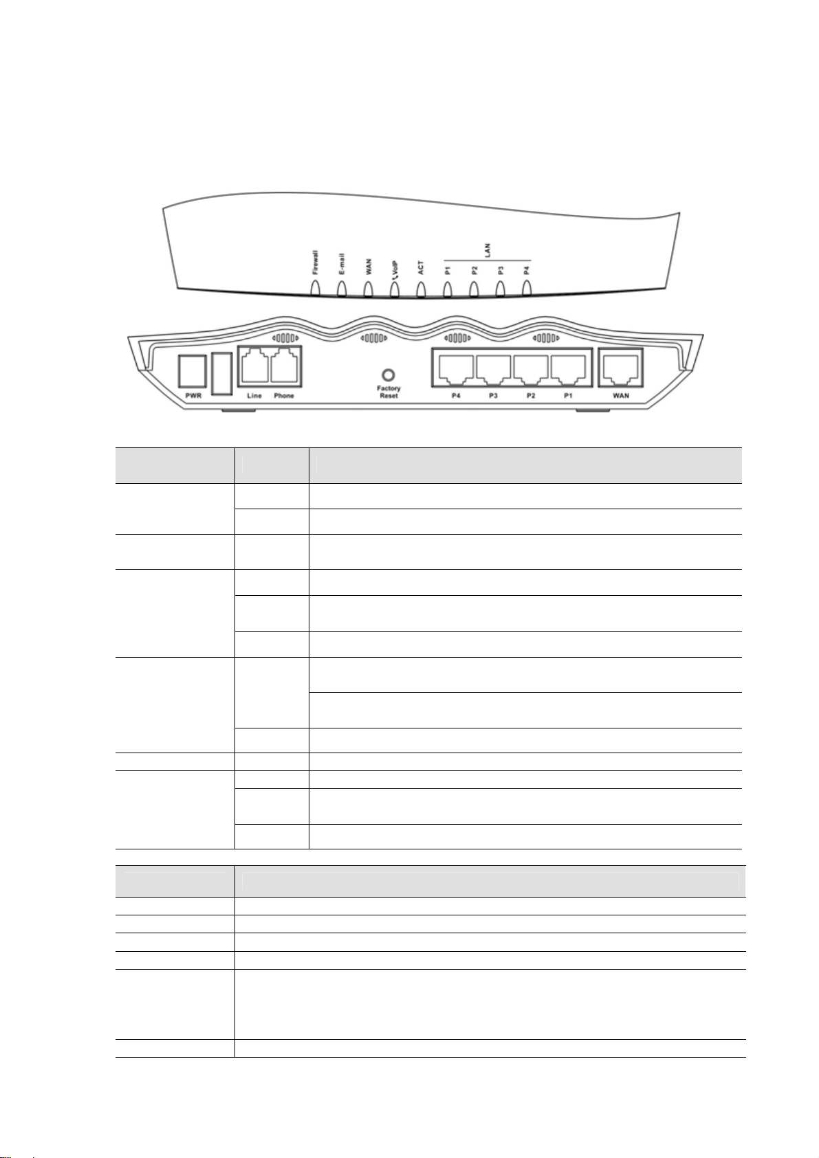
1.3.1 Vigor2100V
LED Status Explanation
Firewall
E-mail
WAN
VoIP
ACT (Activity) on The router is powered on and running properly.
LAN
(P1, P2, P3, P4)
Interface Description
on The firewall function is active.
blinking When encountering DoS attacks.
blinking
orange A normal 10Mbps connection is thro ugh its corresponding po rt.
green
blinking Ethernet packets are transmitting.
green
orange Solid light when phone call is via PSTN life line.
orange A normal 10Mbps connection is thro ugh its corresponding po rt.
green
blinking Ethernet packets are transmitting.
When detecting one or more user-defined E-mails existing on
mail server.
A normal 100Mbps connection is through its corresponding
port.
Solid light when the handset of phone is picked up (off
hooked).
Blinking per 2 seconds when phone is connected through
VoIP.
A normal 100Mbps connection is through its corresponding
port.
PWR
Line
Phone
WAN
Factory Reset
P1, P2, P3, P4
Connect the included power adapter to the power outlet.
Connect to the analog phone line for PSTN life line.
Connect to the analog phone for VoIP communication.
Connect the Cable/ADSL modem to access the Internet.
Restore the default settings. Usage: Turn on the router (ACT LED is
blinking), press the hole and keep for more than 5 seconds. When the ACT
LED begins to blink rapidly, release the button. Then the router will restart
with the factory default configuration.
Connect to the local network devices.
4
Page 11
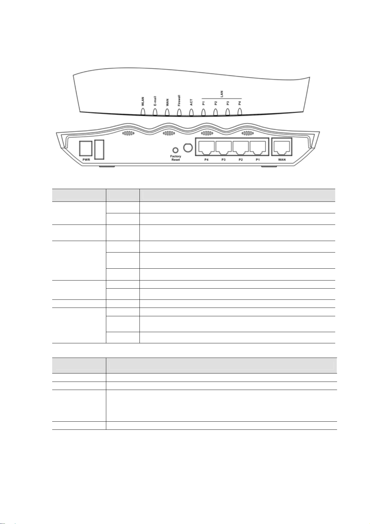
1.3.2 Vigor2100G
LED Status Explanation
on The Wireless LAN function is active.
WLAN
blinking Data packets are transmitted over Wireless LAN.
E-mail
blinking
When detecting one or more user-defined e-mails existing on
mail server.
orange A normal 10Mbps connection is thro ugh its corresponding po rt.
WAN
green
A normal 100Mbps connection is through its corresponding
port.
blinking Ethernet packets are transmitting.
on The firewall function is active.
Firewall
blinking When encountering DoS attacks.
ACT (Activity) on The router is powered on and running properly.
orange A normal 10Mbps connection is thro ugh its corresponding po rt.
LAN
(P1, P2, P3, P4)
green
blinking Ethernet packets are transmitting.
A normal 100Mbps connection is through its corresponding
port.
Interface Description
PWR
WAN
Connect the included power adapter to the power outlet.
Connect the Cable/ADSL modem to access the Internet.
Restore the default settings. Usage: Turn on the router (ACT LED is
Factory Reset
blinking), press the hole and keep for more than 5 seconds. When the ACT
LED begins to blink rapidly, release the button. Then the router will restart
with the factory default configuration.
P1, P2, P3, P4
Connect to the local network devices.
5
Page 12
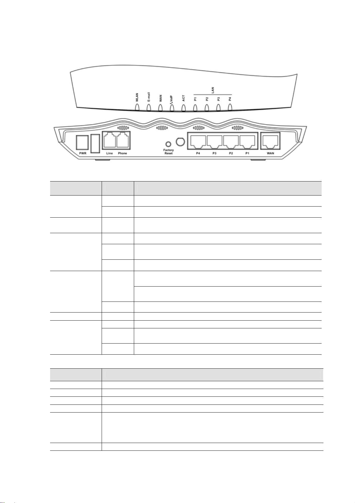
1.3.2 Vigor2100VG
LED Status Explanation
WLAN
E-mail
WAN
VoIP
ACT (Activity) on The router is powered on and running properly.
LAN
(P1, P2, P3, P4)
Interface Description
on The Wireless LAN function is active.
blinking Data packets are transmitted over Wireless LAN.
blinking
orange A normal 10Mbps connection is thro ugh its corresponding po rt.
green
blinking Ethernet packets are transmitting.
green
orange Solid light when phone call is via PSTN life line.
orange A normal 10Mbps connection is thro ugh its corresponding po rt.
green
blinking Ethernet packets are transmitting.
When detecting one or more user-defined e-mails existing on
mail server.
A normal 100Mbps connection is through its corresponding
port.
Solid light when the handset of phone is picked up (off
hooked).
Blinking per 2 seconds when phone is connected through
VoIP.
A normal 100Mbps connection is through its corresponding
port.
PWR
Line
Phone
WAN
Factory Reset
P1, P2, P3, P4
Connect the included power adapter to the power outlet.
Connect to the analog phone line for PSTN life line.
Connect to the analog phone for VoIP communication.
Connect the Cable/ADSL modem to access the Internet.
Restore the default settings. Usage: Turn on the router (ACT LED is
blinking), press the hole and keep for more than 5 seconds. When the ACT
LED begins to blink rapidly, release the button. Then the router will restart
with the factory default configuration.
Connect to the local network devices.
6
Page 13

1.4 Package Contains
Quick Start Guide CD
UK-type power adapter EU-type power adapter
USA/Taiwan-type power
adapter
RJ-45 Cable (Ethernet) RJ-11 Cable for Vigor2100VG/V
Antenna for Vigor2100VG/G
AU/NZ-type power adapter
7
Page 14

2. Quick Install Your Vigor2100 Series Router
2.1 Hardware Installation
Before starting to configure the router, you have to connect your devices
correctly.
1. Connect the WAN interface to the external Cable/ADSL modem with a RJ-45
cable.
2. Connect one port of 4-port switch to your computer with a RJ-45 cable.
3. For Vigor2100VG/V, connect Phone port to a conventional analog telephone,
either corded or wireless (DECT), with a RJ-11 cable.
4. For Vigor2100VG/V, connect Line port to land line jack with a RJ-11 cable.
5. Connect the attached power adapter to the power port.
6. Check the ACT and WAN, LAN LEDs to assure network connections.
(Regarding the detailed LED status explanation, please refer to section 1.3)
Caution For Vigor2100VG/V, the FXS port can be connected to an
analog phone only. Do not connect the FXS port to the telephone wall jack.
This connection might damage your router.
8
Page 15

2.2 Configure Your Router via Quick Start Wizard
Introduction
The Quick Start Wizard is designed for you to easily set up your broadband
Internet access. You can directly access the Quick Start Wizard via Web
Configurator.
Configure Your Router via Quick Start Wizard
Step 1.
Open the web browser on a PC which is connected to the router and
then link to the gateway IP address of the router (the default setting is
192.168.1.1). Once your link (http://192.168.1.1) is successful, a pop-up
window will open to ask for username and password. Leave the default
null value and press OK to continue.
Step 2.
If you fail to access to the web configuration, please refer to “Trouble
Shooting” guide.
The Main Menu will pop out after completing previous step.
9
Page 16

Step 3.
Now Quick Start Wizard is switched on. Enter login password. Then
click Next to continue.
Step 4.
Step 5
Select the appropriate TIME ZONE for your location.
Select the appropriate Internet connection type to your ISP.
In terms of several Internet connection type, please follow procedures as below:
PPPoE
users
Enter your user name and password provided by your ISP.
10
Page 17

PPTP
users
Dial on Demand : The router will ONLY connect to your ISP on demand.
By “on demand”, it means when any LAN user attempt to send data onto the
Internet. When there is no data traffic, the router will close the connection to
the ISP because there is no demand.
Idle timeout: This is the time setting If there being no Internet traffic for a
period, for example 10 minutes.
Always On: The router will keep a permanent connection to the ISP
automatically.
Enter your user name and password provided by your ISP.
Obtain an IP address automatically: Set the WAN interface as a DHCP
11
Page 18

Static IP
client that will ask for the IP network settings from the DHCP server or
PPTP-enabled DSL modem.
Specify an IP address: If you are not sure whether there are any DHCP
services on the WAN interface, you can manually assign an IP address to the
interface. Note that the IP Address and Subnet Mask should be assigned
within the same network as the PPTP-enabled DSL modem.
Enter the static (fixed or permanent) IP address that your ISP offers to you.
DHCP
WAN IP address: this is the IP address assigned by your ISP for your router.
You shall specify the IP address of the router here. e.g. 172.16.2.84
Subnet Mask: an address code that determines the size of the network; this
is the subnet mask of the router, when seen by external users on the Internet
(including your ISP). The subnet mask is provided by your ISP. e.g.
255.255.255.0
Gateway IP Address: an IP address forwards Internet traffic from your local
area network (LAN) . e.g. 172.16.2.5
DNS Server IP address: you must specify DNS server IP address here if
your ISP has the said address. If you do not specify it, the router will
automatically apply default DNS Server IP address: 194.109.6.66 to this
field.
Some Cable ISPs require user to provide or specify MAC address for access
authentication purpose. Your can either manually enter the MAC address in
the MAC Address fields or clone from your network adapter.
12
Page 19

Step 6
Review the summary of settings.
Vigor2100VG/V apply efficient codecs designed to make the best use of
available bandwidth. Vigor2100VG/V also equip with automatic QoS
assurance. QoS Assurance assists to assign higher priority to voice traffic via
Internet for better talking/hearing enjoyment. To achieve that, you will always
have the required inbound and outbound bandwidth that is prioritized exclusively
for Voice traffic over Internet. Your data will arrive a little bit later in a tolerable
manner.
On the bottom of Web Configurator window, you can find messages showing the
system interaction with you.
“Ready” indicates the system is ready for you to input settings.
“Settings Saved” means your settings are saved once you click “Finish” or
“OK” button.
13
Page 20

3. Wireless LAN Settings(for G models)
This section will guide you to operate the capabilities of Wireless LAN instantly
on the router. Please follow the menu tree of the Wireless LAN configuration
below to set up wireless function.
Wireless LAN >> General Settings
Security
Access Control
Station List
The Frequency Domain is set as Europe. (The default value of Frequency Domain
was set by factory depends on the reselling region.)
3.1 General Settings
Click General Settings to configure the Service Set Identifier (SSID) and
wireless channel.
14
Page 21

1. Enable Wireless LAN:
Check the box to enable wireless function.
2. Mode:
Select an appropriate wireless mode.
Mixed (11b+11g): The radio can support both IEEE802.11b and
IEEE802.11g protocols simultaneously.
11g-only: The radio only supports IEEE802.11g protocol.
11b-only: The radio only supports IEEE802.11b protocol.
3. Scheduler:
Set the wireless LAN to work at some time interval only. You may choose
up to 4 out of 15 schedules that should be defined under Advanced
Setup > Call Schedule Setup. Please refer to the User’s Guide.
4. SSID and Channel:
The default SSID is "default". We suggest you change it to a particular
name. In this case, SSID was changed to “DrayTek”.
SSID (Service Set Identifier): It is used to name the wireless LAN, and
must have the same content in client PC/notebook wireless card(s). SSID
can be any text numbers or various special characters.
Channel: A wireless channel for the router. The default channel is 6. You
can change it to more appropriate one if the selected channel is under
serious interference.
5. Hide SSID:
Check it to prevent from wireless sniffing and make it harder for
unauthorized clients to join your wireless LAN.
3.2 Security
Click Security to configure the security options.
15
Page 22

1. Mode:
Select an appropriate encryption to improve the security and privacy of
your wireless data packets.
Disable: Turn off the encryption mechanism.
WEP Only: Accepts only WEP clients and the encryption key should be
WEP or WPA/PSK: Accepts WEP and WPA clients simultaneously and the
WPA/PSK Only: Accepts only WPA clients and the encryption key should
2. WPA:
The WPA encrypts each frame transmitted from the radio using the
pre-shared key (PSK) which entered from this panel.
Pre-Shared Key (PSK): Either 8~63 ASCII characters or 64 Hexadecimal
digits leading by 0x can be entered. For example "0123456789ABCD...."
or "0x321253abcde.....".
3. WEP:
64-Bit: For 64bits WEP key, either 5 ASCII characters or 10 hexadecimal
128-Bit: For 128bits WEP key, either 13 ASCII characters or 26
entered in WEP Key.
encryption key should be entered in WEP Key and PSK respectively.
be entered in PSK.
digitals leading by 0x can be entered. For example, ABCDE or
0x4142434445.
hexadecimal digits leading by 0x can be entered. For example,
ABCDEFGHIJKLM or 0x4142434445464748494A4B4C4D.
128-Bit WEP is securer than 64-Bit, but has more encryption/decryption
overhead. To communicate, all wireless devices must support the same
WEP encryption bit size and have the same key. Only one key out of
four preset keys can be selected at one time. The keys can be entered
either in ASCII or in Hexadecimal. To indicate which key you wish to
use, click the circle under Use next to the key.
16
Page 23

4. VoIP Settings (for V models)
Hardware Connection
The Vigor2100VG/V have one FXS port, the “Phone” port on the rear panel. As
mentioned in previous section 2.1 Hardware Installation, you will have to
connect it to a conventional analog telephone, either corded or wireless (DECT).
Before you start to talk
SIP is an end-to-end, signaling protocol that establishes user presence and
mobility in VoIP structure. Every one who wants to talk using SIP protocol will
need a “SIP Address”. The standard format of SIP Address is
display name<username @ domain name of SIP Registrar >.
It is very similar to a URL so some may call it “SIP URL”.
Usually there will be two types of calling scenario, as illustrated below:
1.Calling via SIP Servers
First, the Vigor VoIP routers of yours will have to register to a SIP Registrar by
sending registration messages. Then, both of your calls will be forwarded to
each other by SIP proxy.
If you both register to the same SIP Registrar, then it will be illustrated as below:
17
Page 24

The major benefit of this mode is that you don’t have to memorize your friend’s
IP address, which might change very frequently if it’s dynamic. Instead of that,
you will only have to using dial plan or directly dial your friend’s account name
if you are with the same SIP Registrar. Please refer to the Example 1 and 2 in
the 4.3 Calling Scenario.
2.Peer-to-Peer
Before calling, you have to know your friend’s IP Address. The Vigor VoIP
Routers will build connection between each other. Please refer to the Example 3
in the 4.3 Calling Scenario.
The menu tree of the VoIP configuration:
VoIP >> DialPlan
SIP Related Function
CODEC / RTP / DTMF
Voice Call Status
QoS
18
Page 25

4.1 DialPlan Setup
In this section, you can set your VoIP contacts in the “phonebook” we called
DialPlan - help you to make calls quickly and easily by using “speed-dial” Phone
Number. There are total 60 index entries in the DialPlan for you to store all your
friends and family members’ SIP addresses.
For each Dial Plan, you will see the settings below:
The detail explanation of the index window:
Enable
Tick this to enable this entry.
Phone Number
Display Name
SIP URL
Loop Through
The “Speed-dial” number of this index. This can be any number
you choose, using digits 0-9 and*
The “Caller-ID” that you want to be displayed on your friend’s
screen. This let your friend can easily know who’s calling without
memorizing lots of SIP URL Address.
Enter your friend’s SIP Address
This function provide comprehensive ways to call your friend.
PSTN: When the router detect your Internet connection is
available, the router will dial SIP URL so your call will be directed
via Internet. If the Internet connection is down, Loop Through
function enable the router automatically dial Backup Phone
Number so your call will be directed via PSTN network. This
ensures your call will always be dialed.
This is important because you don’t want your call get trapped in
the VoIP mechanism. Please be sure to fill in the Backup Phone
Number.
None: The router will always dial SIP URL no matter what the
status of Internet connection is. It might cause your call failed due
to the Internet connection might not be available.
19
Page 26

Although the Loop Through function provides convenient
live lines for your call, you might prefer None for directing
all calls via Internet. Please be reminded that you can still
make the call via PSTN by manually dialing “#0” first.
This will also work if you may wish to know in which way
every call dial out so that you can count how much they
save before receiving the phone bill.
Backup Phone
Number
The telephone number to dial if you select PSTN in Loop
Through
4.2 SIP Related Function Setup
In this section, you set up your own SIP settings. When you apply for an account,
your SIP service provider will give you an Account Name or user name, SIP
Registrar, Proxy, and Domain name. (The last three might be the same in
some case).Then you can tell your folks your SIP Address as in Account
Name@ Domain name
As Vigor VoIP Router is turned on, it will first register with Registrar using
AuthorizationUser@Domain/Realm. After that, your call will be bypassed by SIP
Proxy to the destination using AccountName@Domain/Realm as identity.
Please set each field in the SIP and Ports Settings accordingly. Click OK to
apply settings.
20
Page 27

The detail explanation of the SIP and Port settings window:
SIP Port
Set the port number for sending/receiving SIP message for building
a session. The default value is 5060. Your peer must set the same
value in his/her Registrar.
Registrar
Proxy
Domain/Realm
Use Registrar
Display Name
Account
Name
Authorization
User
Password
Expire Time
Set the domain name or IP address of the SIP Registrar server.
Set domain name or IP address of SIP proxy server. If this setting
value is the same as Registrar, please press “Duplicate”.
Set the domain name or IP address field of SIP Address. e.g., every
text after @. If this setting value is the same as Registrar, please
press “Duplicate”.
With the Registrar domain entered above, tick this box to let the
Vigor2100 series use the SIP Registrar.
The “caller-ID” that you want to be displayed on your friend’s screen.
Enter your account name of SIP Address, e.g. every text before @.
Enter the name or number used for SIP Authorization with SIP
Registrar. If this setting value is the same as Account Name, please
press “Duplicate”.
The password provided to you when you registered with a SIP
service.
The time duration that your SIP Registrar server keeps your
registration record. Before the time expires the Vigor2100 series will
send another register request to SIP Registrar again.
21
Page 28

In the “VoIP Call Status” you will find an “R” indicating you have registered with
your SIP server.
22
Page 29

4.3 Calling Scenario
Calling via SIP Sever
Example 1
John and David both have a SIP Address from different service providers.
John’s SIP URL: 1234@draytel.org
David’s SIP URL: 4321@iptel.org
John’s settings
DialPlan index 1
Phone Number: 1111
Display Name: David
SIP URL: 4321@iptel.org
SIP Related Function
SIP Port: 5060 (default)
Registrar: draytel.org
Proxy: (Duplicate)
Domain/Realm: (Duplicate)
Port 1:
Use Registrar: (checked)
Display Name: john
Account Name: 1234
Authorization User: (Duplicate)
Password: ******
Expiry Time: (use default value)
CODEC/RTP/DTMF
(use default value)
David’s settings
DialPlan index 1
Phone Number:2222
Display Name: John
SIP URL:1234@draytel.org
SIP Related Function
SIP Port: 5060(default)
Registrar: iptel.org
Proxy: (Duplicate)
Domain/Realm: (Duplicate)
Port 1:
Use Registrar: (checked)
Display Name: david
Account Name: 4321
Authorization User: (Duplicate)
Password: ******
Expiry Time: (use default value)
CODEC/RTP/DTMF
(use default value)
John calls David
he picks up the phone and dials
1111#. (DialPlan Phone Number
for David)
David calls John
he picks up the phone and dials
2222# (DialPlan Phone Number
for John)
23
Page 30

Example 2
John and David both have a SIP Address from the same service provider.
John’s SIP URL: 1234@draytel.org
David’s SIP URL: 4321@draytel.org
John’s settings
DialPlan index 1
Phone Number: 1111
Display Name: David
SIP URL: 4321@draytel.org
SIP Related Function
SIP Port: 5060 (default)
Registrar: draytel.org
Proxy: (Duplicate)
Domain/Realm: (Duplicate)
Port 1:
Use Registrar: (checked)
Display Name: john
Account Name: 1234
Authorization User: (Duplicate)
Password: ******
Expiry Time: (use default value)
CODEC/RTP/DTMF
(use default value)
David’s settings
DialPlan index 1
Phone Number:2222
Display Name: John
SIP URL:1234@draytel.org
SIP Related Function
SIP Port: 5060(default)
Registrar: draytel.org
Proxy: (Duplicate)
Domain/Realm: (Duplicate)
Port 1:
Use Registrar: (checked)
Display Name: david
Account Name: 4321
Authorization User: (Duplicate)
Password: ******
Expiry Time: (use default value)
CODEC/RTP/DTMF
(use default value)
Or
John calls David
he picks up the phone and dials
1111#. (DialPlan Phone Number
for David)
John calls David
he picks up the phone and dials
4321#. (David’s Account Name)
David calls John
he picks up the phone and dials
2222# (DialPlan Phone Number
for John)
David calls John
he picks up the phone and dials
1234# (John’s Account Name)
24
Page 31

Peer-to-Peer Calling
Example 3
Arnor and Paulin each have a Vigor2500V router, they can call each other
without SIP Registrar. First they will have each other’s IP address and assign an
Account Name for the port used for calling.
Arnor’s SIP URL: 1234@214.61.172.53
Paulin’s SIP URL: 4321@ 203.69.175.24
Arnor’s settings
DialPlan index 1
Phone Number: 1111
Display Name: paulin
SIP URL: 4321@ 203.69.175.24
SIP Related Function
SIP Port: 5060 (default)
Registrar: (blank)
Proxy: (blank)
Domain/Realm: (blank)
Port 1:
Use Registrar: (unchecked)
Display Name: arnor
Account Name: 1234
Authorization User: (blank)
Password: (blank)
Expiry Time: (use default value)
CODEC/RTP/DTMF
(use default value)
Paulin’s settings
DialPlan index 1
Phone Number:2222
Display Name: arnor
SIP URL: 1234@214.61.172.53
SIP Related Function
SIP Port: 5060(default)
Registrar: (blank)
Proxy: (blank)
Domain/Realm: (blank)
Port 1:
Use Registrar: (unchecked)
Display Name: paulin
Account Name: 4321
Authorization User: (blank)
Password: (blank)
Expiry Time: (use default value)
CODEC/RTP/DTMF
(use default value)
John calls David
he picks up the phone and dials
1111#. (DialPlan Phone Number
for David)
David calls John
he picks up the phone and dials
2222# (DialPlan Phone Number
for John)
25
Page 32

5. Trouble Shooting
This section will guide you to solve abnormal situations. Please follow the
below steps to check your basic installation.
Step 1. Is the Hardware Status OK?
1. Check the power line and WLAN/LAN cable connections. Refer
to the Quick Installation Guide “2.1 Hardware Installation” section
for details.
2. Turn on the router, check if the ACT LED blink once per second
and the correspondent LAN LED is bright.
Step 2.
Are the Network Connection Settings on Your PC OK?
The following example is based on Windows XP case. Regarding to
the examples of other OSs, please refer to the similar steps or find
support notes in www.draytek.com.
1. Go to Control Panel and then double-click on Network
Connections.
2. Right-click on Local Area Connection and click on Properties.
26
Page 33

3. Select on Internet Protocol (TCP/IP) and then click Properties.
4. Select Obtain an IP address automatically and Obtain DNS
server address automatically.
27
Page 34

Step 3 Can You Ping the Router from PC?
The default gateway IP address of the router is 192.168.1.1. Please
check that if you can ping the router correctly.
A. For Windows
1. Open the Command Prompt window (from start menu> Run )
2. Type command (for Windows 95/98/ME) or cmd (for Windows
NT/ 2000/XP).
3. Type ping 192.168.1.1 and press [Enter]
B. For Mac (Terminal)
The important thing is that the computer receives a reply from
192.168.1.1. If not, please check the IP address of your PC. We
suggest you set the network connection as get IP automatically.
(Please refer to the Step 2)
28
Page 35

Step 4 Are the ISP Settings OK?
1. Go to the web configuration GUI and check your ISP settings.
2. Click Internet Access Setup items on the left frame of GUI.
A. For PPPoE Users
1. Check that whether the Enable option is selected.
2. Check that whether the Username and Password are entered
with correct value given by your ISP.
B. For Static or Dynamic Users
1. Check that whether the Enable option is selected.
2. Check that whether WAN IP Network Settings is set
appropriately or not. You need to enter “Specify an IP address”,
IP Address, Subnet Mask, and Gateway IP Address with the
correct value.
29
Page 36

C. For PPTP Users
1. Check that whether the Enable option is selected.
2. Check that whether PPTP Server, Username, Password is
entered the correct value given by your ISP.
3. Check that whether LAN2/WAN IP Network Settings is set
appropriately or not. You need to enter “Specify an IP address”,
IP Address and Subnet Mask with the correct value.
If the router settings are correct at all, and the router still does not
connect, please contact your ISP technical support representative
to help you for configuration.
Step 5. Back to Factory Default Setting
Warming: After pressing the "factory default setting", you will loose all
settings you did before. Make sure you have recorded all useful settings.
The password of factory default is null.
A Software Reset
You can also reset router to factory default via Web configurator.
B Hardware Reset
While the router is running (ACT LED blinking), press the button
and hold for more than 5 seconds. The ACT LED begins to blink
30
Page 37

rapidly, then release the button. The router will restart with the
factory default configuration.
After restore the factory default setting, please repeat Step 1 to Step
4 to reinstall the router. Configure the router according to your
recorded settings.
If the router does not work correctly, please contact your dealer for help. For any
further questions, please send e-mail to support@draytek.com
31
 Loading...