

Page 1
i
Page 2

Vigor2862 Series
VDSL2 Security Firewall
Quick Start Guide
(for RF Model)
Version: 1.3
Firmware Version: V3.8.8
(For future update, please visit DrayTek web site)
Date: March 6, 2018
ii
Page 3

Intellectual Property Rights (IPR) Information
Copyrights
Trademarks
© All rights reserved. This publication contains information that is protected
by copyright. No part may be reproduced, transmitted, transcribed, stored in
a retrieval system, or translated into any language without written permission
from the copyright holders.
The following trademarks are used in this document:
Microsoft is a registered trademark of Microsoft Corp.
Windows, Windows 95, 98, Me, NT, 2000, XP, Vista, 7, 8 and Explorer are
trademarks of Microsoft Corp.
Apple and Mac OS are registered trademarks of Apple Inc.
Other products may be trademarks or registered trademarks of their
respective manufacturers.
Safety Instructions and Approval
Safety
Instructions
Read the installation guide thoroughly before you set up the router.
The router is a complicated electronic unit that may be repaired only be
authorized and qualified personnel. Do not try to open or repair the
router yourself.
Do not place the router in a damp or humid place, e.g. a bathroom.
Do not stack the routers.
The router should be used in a sheltered area, within a temperature
range of +5 to +40 Celsius.
Do not expose the router to direct sunlight or other heat sources. The
housing and electronic components may be damag ed by dire ct sunlight or
heat sources.
Do not deploy the cable for LAN connection outdoor to prevent electronic
shock hazards.
Keep the package out of reach of children.
When you want to dispose of the router, please follow local regulations on
conservation of the environment.
Warranty
We warrant to the original end user (purchaser) that the router will be free
from any defects in workmanship or materials for a period of two (2) years
from the date of purchase from the dealer. Please keep your purchase receipt
in a safe place as it serves as proof of date of purchase. During the warranty
period, and upon proof of purchase, should the product have indications of
failure due to faulty workmanship and/or materials, we will, at our discretion,
repair or replace the defective products or components, without charge for
either parts or labor, to whatever extent we deem necessary tore-store the
product to proper operating condition. Any replacement will consist of a new
or re-manufactured functionally equivalent product of equal value, and will
be offered solely at our discretion. This warranty will not apply if the produ ct
is modified, misused, tampered with, damaged by an act of God, or subjected
to abnormal working conditions. The warranty does not cover the bundled or
licensed software of other vendors. Defects which do not significantly affect
the usability of the product will not be covered by the warranty. We reserve
the right to revise the manual and online documentation and to make changes
from time to time in the contents hereof without obligation to notify any
person of such revision or changes.
i
Page 4
Declaration of Conformity
Hereby, DrayTek Corporation declares that the radio equipment type Vigor286 2 is in complia nce with
Directive 2014/53/EU.
The full text of the EU Declaration of Conformity is available at the following internet address:
http://www.draytek.com.tw/ftp/Vigor2862/Document/CE/
Manufacturer: DrayTek Corp.
Address: No. 26, Fu Shing Road, HuKou Township, HsinChu Industrial Park, Hsin-Chu County,
Taiwan 303
Product: Vigor2862 Series
Frequency Information for Europe area:
2.4G WLAN 2412MHz - 2472 MHz, max. TX power: 19.98dBm *1
5G WLAN 5180MHz - 5700 MHz, max. TX power: 27.00dBm *2
LTE B1[1920-1980 MHz (TX); 2110-2170 MHz (RX)]; B3[1710-1785 MHz (TX);
1805-1880 MHz (RX)]; B7[2500-2570 MHz (TX); 2620-2690 MHz (RX)];
B8[880-915 MHz (TX); 925-960 MHz (RX)]; B20[832-862 MHz (TX); 791-821
MHz (RX)]; *3
3G B1[1920-1980 MHz (TX); 2110-2170 MHz (RX)]; B8[880-915 MHz (TX); 925-960
MHz (RX)] *3
2G 900[880-915 MHz (TX); 925-960 MHz (RX)]; 1900[1710-1785 MHz (TX);
1805-1880 MHz (RX)] *3
Requirements in AT/BE/BG/CZ/DZ/DK/EE/FR/DE/IS/IE/IT/EL/ES/
CY/LV/LI/LT/LU/HU/MT/NL/NO/PL/PT/RO/SI/SK/TR/FI/SE/CH/
UK/HR. 5150MHz~5350MHz is for indoor use only.
(*1: for 2.4G WLAN model; *2: for 5G WLAN model; *3: for LTE model)
This product is designed for LTE, POTS, DSL and 2.4GHz /5GHz WLAN network throughout the EC
region.
Regulatory Information
Federal Communication Commission Interference Statement
This equipment has been tested and found to comply with the limits for a Class B digital device,
pursuant to Part 15 of the FCC Rules. These limits are designed to provide reasonable protection
against harmful interference in a residential installation. This equipment generates, uses and can
radiate radio frequency energy and, if not installed and used in accordance with the instructions, may
cause harmful interference to radio communications. However, there is no guarantee that
interference will not occur in a particular installation. If this equipment does cause harmful
interference to radio or television reception, which can be determined by turning the equipment off
and on, the user is encouraged to try to correct the interference by one of the following measures:
Reorient or relocate the receiving antenna.
Increase the separation between the equipment and receiver.
Connect the equipment into an outlet on a circuit different from that to which the receiver
is connected.
Consult the dealer or an experienced radio/TV technician for help.
ii
Page 5

This device complies with Part 15 of the FCC Rules. Operation is subject to the following two
conditions:
(1) This device may not cause harmful interference, and
(2) This device may accept any interference received, including interference that may cause
undesired operation.
Caution: Any changes or modifications not expressly approved by the party responsible for
compliance could void the user's authority to operate the equipment.
The antenna/transmitter should be kept at least 20 cm away from human body.
DrayTek Vigor2862 series VDSL2/ADSL2+ routers are compliant with 47 C.F.R. Part 68.
More update, please visit www.draytek.com.
iii
Page 6

Be a Registered Owner
Web registration is preferred. You can register your Vigor router via http://www.draytek.com.
Firmware & Tools Updates
Due to the continuous evolution of DrayTek technology, all routers will be regularly upgraded.
Please consult the DrayTek web site for more information on newest firmware, tools and
documents. http://www.draytek.com
iv
Page 7

TTaabbllee ooff CCoonntteennttss
1. Introduction........................................................................................................... 1
2. Package Content .................................................................................................. 2
3. Panel Explanation................................................................................................. 3
3.1 Vigor2862L................................................................................................................................. 3
3.2 Vigor2862n / Vigor2862ac / Vigor2862Bn / Vigor2862Ln / V igor2862Lac........................................... 5
3.3 Vigor2862Vac.............................................................................................................................9
3.4 Notes for Antenna Installation (for “L” model)...........................................................................11
3.5 Notes for Y Cable Application...................................................................................................13
4. Hardware Installation ......................................................................................... 14
4.1 Network Connection................................................................................................................. 14
4.2 Wall-Mounted Installation......................................................................................................... 15
5. Software Configuration...................................................................................... 16
5.1 Quick Start Wizard for Network Connection............................................................................. 16
6. Customer Service............................................................................................... 22
v
Page 8
11.. IInnttrroodduuccttiioonn
Vigor2862 series is a VDSL2 router with multi-subnet for secure and efficient
workgroup management. It integrates IP layer QoS, NAT session/bandwidth
management to help users control works well with large bandwidth.
By adopting hardware-based VPN platform and hardware encryption of
AES/DES/3DES, and hardware key hash of SHA-1/MD5, the router increases the
performance of VPN greatly and offers several protocols (such as
IPSec/PPTP/L2TP) with up to 32 VPN tunnels.
The object-based design used in SPI (Stateful Packet Inspection) firewall allows
users to set firewall policy with ease. CSM (Content Security Management)
provides users control and management in IM (Instant Messenger) and P2P (Peer
to Peer) more efficiency than before. In addition, DoS/DDoS prevention and
URL/Web content filter strengthen the security outside and control inside.
Vigor2862 series supports USB interface for connecting USB printer to share
printing function, 3G/4G USB modem for network connection, connectivity for
network FTP service, or thermometer for monitoring the temperature change.
Vigor2862 “B” series can enhance the transmission rate and enlarge the
bandwidth by combining two standard VDSL2 lines, thus it is able to provide low
line prices instead of expensive leased lines. Meanwhile, the speed of existing
connection established for customers can be increased.
1
Page 9
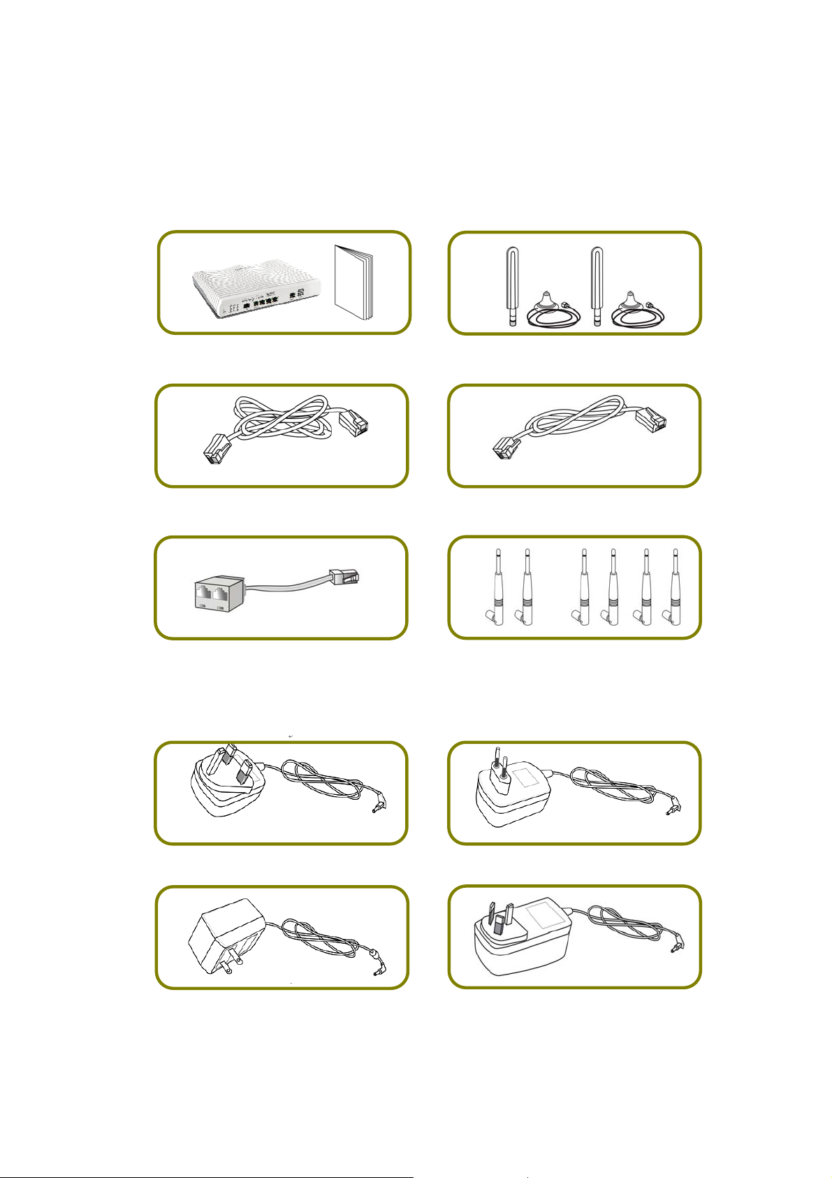
22.. PPaacckkaaggee CCoonntteenntt
Take a look at the package content. If there is anything missed or damaged,
please contact DrayTek or dealer immediately.
Vigor Router & Quick Start Guide
Antenna + Socket (L models)
RJ-45 to RJ-45 Cable
(Annex B)
RJ-11 to RJ-45 Cable (Annex B)
RJ-11 to RJ-11 Cable (Annex A)
The type of the power adapter depends on the country that the router will be
installed. * The maximum power consumption is 30 Watt.
UK-type Power Adapter
Y Cable (B models)
EU-type Power Adapter
or
Antenna (n or ac models)
USA/Taiwan-type Power Adapter
AU/NZ-type Power Adapter
2
Page 10

33.. PPaanneell EExxppllaannaattiioonn
33..11 VViiggoorr22886622LL
LED Status Explanation
WAN2
LTE
DSL
WCF
USB
VPN
DMZ
LED on Connector
Off The router is powered off. ACT (Activity)
Blinking The router is powered on and running
normally.
On Internet connection is ready.
Off Internet connection is not ready.
Blinking The data is transmitting.
On The QoS function is active. QoS
Off The QoS function is inactive.
On LTE device is connected and ready for use.
Off LTE device is not detected, or has serious
problem (e.g., no SIM card, SIM pin error, SIM
deactivated, and etc.).
Blinking Slowly: LTE device is in dialing up.
Quickly: The data is transmitting.
On The router is ready to access Internet through
DSL link.
Blinking Slowly: The DSL connection is ready.
Quickly: The connection is training.
On The Web Content Filter is active. (It is enabled
from Firewall >> General Setup).
Off WCF is disabled.
On USB device is connected and ready for use.
Off No USB device is connected.
Blinking The data is transmitting.
On The VPN tunnel is active.
Off VPN services are disabled
Blinking Traffic is passing through VPN tunnel.
On The DMZ function is enabled.
Off The DMZ function is disabled.
Blinking The data is transmitting.
Left
LAN
P1~P4
LED
On The port is connected.
Off The port is disconnected.
Blinking The data is transmitting.
3
Page 11

P5/
WAN2
Right
LED
Left
LED
Right
LED
On The port is connected with 1000Mbps.
Off The port is connected with 10/100Mbps
On The port is connected.
Off The port is disconnected.
Blinking The data is transmitting.
On The port is connected with 1000Mbps.
Off The port is connected with 10/100Mbps
The port “P5 / WAN2” is switchable. It can be used for LAN connection or WAN
connection according to the settings configured in WUI.
Switch on Rear Side (Jack for LTE device)
Interface Description
Factory Reset
Restore the default settings. Usage: Turn on the router
(ACT LED is blinking). Press the hole and keep for more than
5 seconds. When you see the ACT LED begins to blink
rapidly than usual, release the but ton. Then t he ro uter will
restart with the factory default configuration.
DSL / DSL 1/2
LAN P1-P4
P5/WAN2
Connecter for accessing the Internet.
Connecters for local network devices.
Connecter for local network devices or modem for
accessing Internet.
USB
Connecter for a USB device (for 3G/4G USB Modem or
printer or thermometer).
PWR Connecter for a power adapter.
ON/OFF Power Switch.
4
Page 12

33..22 VViiggoorr22886622nn // VViiggoorr22886622aacc // VViiggoorr22886622BBnn // VViiggoorr2
VViiggoorr22886622LLaacc
2886622LLnn //
LED Status Explanation
Off The router is powered off. ACT (Activity)
Blinking The router is powered on and running
normally.
WAN2
LTE
On Internet connection is ready.
Off Internet connection is not ready.
Blinking The data is transmitting.
On The QoS function is active. QoS
Off The QoS function is inactive.
On LTE device is connected and ready for use.
Off LTE device is not detected, or has serious
problem (e.g., no SIM card, SIM pin error, SIM
deactivated, and etc.).
Blinking Slowly: LTE device is in dialing up.
Quickly: The data is transmitting.
5
Page 13

DSL / DSL 1/2
WCF
USB
2.4G/5G/WLAN
VPN
DMZ
LED on Connector
On The router is ready to access Internet through
DSL link.
Blinking Slowly: The DSL connection is ready.
Quickly: The connection is training.
On The Web Content Filter is active. (It is
enabled from Firewall >> General Setup).
Off WCF is disabled.
On USB device is connected and ready for use.
Off No USB device is connected.
Blinking The data is transmitting.
On
2.4G/5G: Wireless access point with
bandwidth of 2.4GHz/5GHz is ready.
WLAN: Wireless access point is ready.
Off Wireless function is disabled.
Blinking
It will blink slowly while wireless traffic goes
through.
ACT and WLAN LEDs blink quickly and
simultaneously when WPS is working, and will
return to normal condition after two minutes.
(You need to setup WPS within 2 minutes.)
On The VPN tunnel is active.
Off VPN services are disabled
Blinking Traffic is passing through VPN tunnel.
On The DMZ function is enabled.
Off The DMZ function is disabled.
Blinking The data is transmitting.
On The port is connected.
Off The port is disconnected.
Blinking The data is transmitting.
On The port is connected with 1000Mbps.
Off The port is connected with 10/100Mbps
On The port is connected.
Off The port is disconnected.
Blinking The data is transmitting.
On The port is connected with 1000Mbps.
Off The port is connected with 10/100Mbps
LAN
P1~P4
P5/
WAN2
Left
LED
Right
LED
Left
LED
Right
LED
The port “P5 / WAN2” is switchable. It can be used for LAN connection or WAN
connection according to the settings configured in WUI.
6
Page 14

Switch on Rear Side (Available for Vigor2862Ln/Lac)
Interface Description
Wireless LAN
ON/OFF/WPS
For Vigor2862n /Vigor2862Bn:
Press the button and release it within 2 seconds. When
the wireless function is ready, the green LED will be on.
Press the button and release it within 2 seconds to turn
off the WLAN function. When the wireless function is not
ready, the LED will be off.
For Vigor2862ac/Vigor2862Ln/Vigor2862Lac:
Wireless band will be switched /changed according to the
button pressed and released. For example,
2.4G (On) and 5G (On) – in default.
2.4G (Off) and 5G (On) – pressed and released the button
once.
2.4G (On) and 5G (Off) – pressed and released the button
7
Page 15

Factory Reset
twice.
2.4G (Off) and 5G (Off) – pressed and released the
button three times.
When WPS function is enabled by web user interface, press
this button for more than 2 seconds to wait for client’s
device making network connection through WPS.
Restore the default settings. Usage: Turn on the router (ACT
LED is blinking). Press the hole and keep for more than 5
seconds. When you see the ACT LED begins to blink rapidly
than usual, release the button. Then the router will restart
with the factory default configuration.
USB1~2
DSL / DSL 1/2
LAN P1-P4
P5 / WAN2
PWR
ON/OFF
Connecter for a USB device (for 3G/4G USB Modem or
printer or thermometer).
Connecter for accessing the Internet.
Connecters for local network devices.
Connecter for local network devices or modem for accessing
Internet.
Connecter for a power adapter.
Power Switch.
8
Page 16

33..33 VViiggoorr22886622VVaacc
LED Status Explanation
Blinking The router is powered on and running normally. ACT
(Activity)
WAN2
DSL
Off The router is powered off.
On USB device is connected and ready for use. USB
Blinking The data is transmitting.
On Internet connection is ready.
Off Internet connection is not ready.
Blinking The data is transmitting.
On The router is ready to access Internet through DSL
link.
Blinking Slowly: The DSL connection is ready.
Quickly: The connection is training.
2.4G/5G
Line
On 2.4G/5G: Wireless access point with bandwidth of
2.4GHz/5GHz is ready.
WLAN: Wireless access point is ready.
Blinking It will blink slowly while wireless traffic goes through.
ACT and WLAN LEDs blink quickly and simultaneously when
WPS is working, and will return to normal condition after
two minutes. (You need to setup WPS within 2 minutes.)
On A PSTN phone call comes (in and out). However,
when the phone call is disconnected, the LED will be
off.
There is no PSTN phone call.
Off
Phone 1/2
On The phone connected to this port is off-hook.
Off The phone connected to this port is on-hook.
Blinking
LED on Connector
Left LED
LAN P1~P4
P5/ WAN2
(Green)
Right LED
(Green)
Left LED
(Green)
Right LED
(Green)
A phone call comes.
On The port is connected.
Off The port is disconnected.
Blinking The data is transmitting.
On The port is connected with 1000Mbps.
Off The port is connected with 10/100Mbps.
On The port is connected.
Off The port is disconnected.
Blinking The data is transmitting.
On The port is connected with 1000Mbps.
Off The port is connected with 10/100Mbps.
The port “P5 / WAN2” is switchable. It can be used for LAN connection or WAN
connection according to the settings configured in WUI.
9
Page 17

Interface Description
Wireless LAN
ON/OFF/WPS
Wireless band will be switched /changed according to the
button pressed and released. For example,
2.4G (On) and 5G (On) – in default.
2.4G (Off) and 5G (On) – pressed and released the button
once.
2.4G (On) and 5G (Off) – pressed and released the button
twice.
2.4G (Off) and 5G (Off) – pressed and released the
button three times.
When WPS function is enabled by web user interface, press
this button for more than 2 seconds to wait for client’s
device making network connection through WPS.
Factory Reset Restore the default settings. Usage: Turn on the router
(ACT LED is blinking). Press the hole and keep for more
than 5 seconds. When you see the ACT LED begins to blink
rapidly than usual, release the button. Then the router will
restart with the factory default configuration.
DSL Connecter for accessing the Internet.
LAN P1~ P4 Connecters for local network devices.
P5 / WAN2 Connecter for local network devices or modem for accessing
Internet.
USB1~USB2 Connector for a USB device (for 3G/4G USB Modem or printer or
Environmental Thermometer).
Phone 1/2 Connecter for analog phone(s).
Line Connector for PSTN life line.
PWR Connecter for a power adapter.
ON/OFF Power Switch.
10
Page 18

33..44 NNootteess ffoorr AAnntteennnnaa IInnssttaallllaattiioonn ((ffoorr ““LL”” mmooddeell))
Magnetic antenna must be installed on the extension base before connecting to Vigor
router.
Extension
Base
There are two mounting holes for installing antennas with extension base on
Vigor router. Please install them as shown below.
Major Signal
Transmitted Hole
SIM Card
Slot
Extension
Base
Note, if only one antenna shall be installed, please use the mounting hole (major signal
transmitted hole) near to the SIM card slot.
11
Page 19

While installing the SIM card into the card slot, note that back plate of the SIM card slot
must be removed first and the direction of card notch must be on the left side.
There are two types of antennas provided for Vigor2862Ln/Vigor2862Lac, which
must be installed in different locations carefully and correctly. Wrong
installation might cause bad signal of wireless connection. Therefore, pay
attention to the installation of antennas by referring to the following illustration.
SMA jack for LTE Antenna
(with extension base)
SMA jack for WLAN
Antenna
12
Page 20

33..55 NNootteess ffoorr YY CCaabbllee AApppplliiccaattiioonn
Y cable is prepared for the one who applies bonding VDSL service (two lines or
one line) to ISP for enhancing the transmission rate and enlarging the bandwidth.
However, the following conditions shall be considered first while installing the
DSL line(s) on to Vigor router.
Condition 1: When the
bonding VDSL service
offered by ISP contains two
DSL1/2
connector of
Vigor router
separate cables, please
insert the Y cable to the
DSL1/2 connector of Vigor
router first. Then, connect
the two VDSL cables to
dual-connector marked
Dual-connector
marked with 1
and 2 on Y cable
with 1 and 2 on Y cable.
Condition 2: When the
bonding VDSL service
offered by ISP contains
only one cable (contains
two VDSL lines), simply
connect it to the DSL1/2
connector of Vigor router.
Condition 3: However,
when the user purchased
bonding VDSL router (e.g.,
B models) but did not
apply for bonding VDSL
service from local ISP, the
Y cable should be inserted
to the DSL1/2 connector of
Vigor router first. Later,
connect the VDSL cable
(contains one VDSL line) to
the dual-connector
marked with 1 to reduce
the unnecessary signal
interference and reduce
the time of signal
detection.
13
Connector
marked with 1
on Y cable
Page 21

44.. HHaarrddwwaarree IInnssttaallllaattiioonn
This section will guide you to install the router through hardware connection and
configure the router’s settings through web browser.
Before starting to configure the router, you have to connect your devices
correctly. (For the hardware connection, we take “ac” model as an example.)
44..11 NNeettwwoorrkk CCoonnnneeccttiioonn
1. Connect the DSL interface to the land line jack with a DSL line cable, or
Connect the cable Modem/DSL Modem/Media Converter to the WAN port of
router with Ethernet cable (RJ-45).
2. Connect one end of an Ethernet cable (RJ-45) to one of the LAN ports of the
router and the other end of the cable (RJ-45) into the Ethernet port on your
computer.
3. Connect one end of the power adapter to the router’s power port on the
rear panel, and the other side into a wall outlet.
4. Power on the device by pressing down the power switch on the rear panel.
5. The system starts to initiate. After completing the system test, the ACT LED
will light up and start blinking. (For the detailed information of LED status,
please refer to section 3. Panel Explanation)
14
Page 22

44..22 WWaallll--MMoouunntteedd IInnssttaallllaattiioonn
Vigor router has keyhole type mounting slots on the underside.
1. A template is provided on the Vigor router packaging box to enable you to
space the screws correctly on the wall.
2. Place the template on the wall and drill the holes according to the
recommended instruction.
3. Fit screws into the wall using the appropriate type of wall plug.
Note
The recommended drill diameter shall be 6.5mm (1/4”).
4. When you finished about procedure, the router has been mounted on the
wall firmly.
15
Page 23

55.. SSooffttwwaarree CCoonnffiigguurraattiioonn
To access Internet, please finish basic configuration after completing the
hardware installation.
55..11 QQuuiicckk SSttaarrtt WWiizzaarrdd ffoorr NNeettwwoorrkk CCoonnnneeccttiioonn
The Quick Start Wizard is designed for you to easily set up your router for
Internet access. You can directly access the Quick Start Wizard via Web
Configurator. Make sure your PC connects to the router correctly.
Note
Open a web browser on your PC and type http://192.168.1.1. A pop-up window
will open to ask for username and password. Please type “admin/admin” as the
Username/Password and click Login.
You may either simply set up your computer to get IP dynamically from
the router or set up the IP address of the computer to be the same
subnet as the default IP address of Vigor router 192.168.1.1. For the
detailed information, please refer to - Trouble Shooting of the user’s
guide.
Note
If you fail to access to the web configuration, please go to “Trouble
Shooting” on User’s Guide for detecting and solving your problem.
16
Page 24

Now, the Main Screen will pop up. Click Wizards>>Quick Start Wizard.
Note
The home page will change slightly in accordance with the router you
have.
If your router can be under an environment with high speed NAT, the
configuration provide here can help you to deploy and use the router quickly.
The first screen of Quick Start Wizard is entering login password. After typing
the password, please click Next.
17
Page 25

On the next page as shown below, please select the WAN interface that you use.
If DSL interface is used, please choose WAN1; if Ethernet interface is used,
please choose WAN2; if 3G USB modem is used, please choose WAN3 or WAN4.
Then click Next for next step. WAN1, WAN2, WAN3 and WAN4 will bring up
different configuration page. Here, we take WAN1 (ADSL/VDSL2) as an example.
Click Next to go to the following page. You have to select the appropriate
Internet access type according to the information from your ISP. For example,
you should select PPPoE mode if the ISP provides you PPPoE interface. In
addition, the field of For ADSL Only will be available only when ADSL is detected.
Then click Next for next step.
18
Page 26

PPPPPPooEE//PPPPPPooAA
1. Choose WAN1 as WAN Interface and click the Next button; you will get the
following page.
2. After finished the above settings, simply click Next.
19
Page 27

3. Please manually enter the Username/Password provided by your ISP. Then
click Next for viewing summary of such connection.
4. Click Finish. A page of Quick Start Wizard Setup OK!!! will appear. Then,
the system status of this protocol will be shown.
5. Now, you can enjoy surfing on the Internet.
20
Page 28

MMPPooAA // SSttaattiicc oorr DDyynnaammiicc IIPP
1. Choose WAN1 as WAN Interface and click the Next button; you will get the
following page.
2. Please type in the IP address/mask/gateway information originally provided
by your ISP. Then click Next for viewing summary of such connection.
3. Click Finish. A page of Quick Start Wizard Setup OK!!! will appear. Then,
the system status of this protocol will be shown.
4. Now, you can enjoy surfing on the Internet.
21
Page 29

66.. CCuussttoommeerr SSeerrvviiccee
If the router cannot work correctly after trying many efforts, please contact your
dealer for further help right away. For any questions, please feel free to send
e-mail to support@draytek.com.
22
 Loading...