

Page 1
i
Page 2

Vigor2133 Series
Gigabit Broadband Router
Quick Start Guide
(for RF Model)
Version: 1.1
Firmware Version: V3.8.6_RC1
(For future update, please visit DrayTek web site)
Date: July 31, 2017
ii
Page 3

Intellectual Property Rights (IPR) Information
Copyrights
Trademarks
© All rights reserved. This publication contains information that is protected
by copyright. No part may be reproduced, transmitted, transcribed, stored in
a retrieval system, or translated into any language without written permission
from the copyright holders.
The following trademarks are used in this document:
Microsoft is a registered trademark of Microsoft Corp.
Windows, Windows 95, 98, Me, NT, 2000, XP, Vista, 7, 8 and Explorer are
trademarks of Microsoft Corp.
Apple and Mac OS are registered trademarks of Apple Inc.
Other products may be trademarks or registered trademarks of their
respective manufacturers.
Safety Instructions and Approval
Safety
Instructions
Read the installation guide thoroughly before you set up the router.
The router is a compl icated electr onic unit that may be rep aired only be
authorized and qualified personnel. Do not try to open or repair the
router yourself.
Do not place the router in a damp or humid place, e.g. a bathroom.
Do not stack the routers.
The router should be used in a sheltered area, within a temperature
range of 0 to +45 Celsius.
Do not expose the router to direct sunlight or other heat sources. The
housing and electronic components may be damaged by direct sunlight
or heat sources.
Do not deploy the cable for LAN connection outdoor to prevent
electronic shock hazards.
Keep the package out of reach of children.
When you want to dispose of the router, please follow local regulations
on conservation of the environment.
Warranty
We warrant to the original end user (purchaser) that the router will be free
from any defects in workmanship or materials for a period of two (2) years
from the date of purchase from the dealer. Please keep your purchase receipt
in a safe place as it serves as proof of date of purchase. During the warranty
period, and upon proof of purchase, should the product have indications of
failure due to faulty workmanship and/or materials, we will, at our discretion,
repair or replace the defective products or components, without charge for
either parts or labor, to whatever extent we deem necessary tore-store the
product to proper operating condition. Any replacement will consist of a new
or re-manufactured functionally equivalent product of equal value, and will
be offered solely at our discretion. This warranty will not apply if the produ ct
is modified, misused, tampered with, damaged by an act of God, or subjected
to abnormal working conditions. The warranty does not cover the bundled or
licensed software of other vendors. Defects which do not significantly affect
the usability of the product will not be covered by the warranty. We reserve
the right to revise the manual and online documentation and to make changes
from time to time in the contents hereof without obligation to notify any
person of such revision or changes.
i
Page 4
Declaration of Conformity
Hereby, DrayTek Corporation declares that the radio equipment type Vigor213 3 is in complia nce with
Directive 2014/53/EU.
The full text of the EU Declaration of Conformity is available at the following internet address:
http://www.draytek.com.tw/ftp/Vigor2133/Document/CE/
Manufacturer: DrayTek Corp.
Address: No. 26, Fu Shing Road, HuKou Township, HsinChu Industrial Park, Hsin-Chu County,
Taiwan 303
Product: Vigor2133 Series
Frequency Information for Europe area:
2.4G WLAN 2412MHz - 2472 MHz, max. TX power: 19.98dBm *1
5G WLAN 5180MHz - 5700 MHz, max. TX power: 27.00dBm *2
Requirements in AT/BE/BG/CZ/DZ/DK/EE/FR/DE/IS/IE/IT/EL/ES/
CY/LV/LI/LT/LU/HU/MT/NL/NO/PL/PT/RO/SI/SK/TR/FI/SE/CH/
UK/HR. 5150MHz~5350MHz is for indoor use only.
(*1: for 2.4G WLAN model; *2: for 5G WLAN model)
This product is designed for 2.4GHz /5GHz WLAN network throughout the EC region.
Regulatory Information
Federal Communication Commission Interference Statement
This equipment has been tested and found to comply with the limits for a Class B digital device,
pursuant to Part 15 of the FCC Rules. These limits are designed to provide reasonable protection
against harmful interference in a residential installation. This equipment generates, uses and can
radiate radio frequency energy and, if not installed and used in accordance with the instructions, may
cause harmful interference to radio communications. However, there is no guarantee that
interference will not occur in a particular installation. If this equipment does cause harmful
interference to radio or television reception, which can be determined by turning the equipment off
and on, the user is encouraged to try to correct the interference by one of the following measures:
Reorient or relocate the receiving antenna.
Increase the separation between the equipment and receiver.
Connect the equipment into an outlet on a circuit different from that to which the receiver
is connected.
Consult the dealer or an experienced radio/TV technician for help.
This device complies with Part 15 of the FCC Rules. Operation is subject to the following two
conditions:
(1) This device may not cause harmful interference, and
(2) This device may accept any interference received, including interference that may cause
undesired operation.
Any changes or modifications not expressly approved by the party responsible for compl iance could
void the user's authority to operate this equipment.
ii
Page 5

This equipment complies with FCC radiation exposure limits set forth for an uncontrolled
environment. This equipment should be installed and operated with minimum distance 20cm between
the radiator and your body.
More update, please visit www.draytek.com.
iii
Page 6

Be a Registered Owner
Web registration is preferred. You can register your Vigor router via http://www.draytek.com.
Firmware & Tools Updates
Due to the continuous evolution of DrayTek technology, all routers will be regularly upgraded.
Please consult the DrayTek web site for more information on newest firmware, tools and
documents.
http://www.draytek.com
iv
Page 7

TTaabbllee ooff CCoonntteennttss
1. Introduction ........................................................................................................... 1
2. Package Content .................................................................................................. 2
3. Panel Explanation ................................................................................................. 3
4. Hardware Installation ........................................................................................... 5
4.1 Network Connection ................................................................................................................... 5
4.2 Wall-Mounted Installation ........................................................................................................... 6
5. Software Configuration ........................................................................................ 7
6. Customer Service ................................................................................................ 11
v
Page 8

11.. IInnttrroodduuccttiioonn
The Vigor2133 series features advanced bandwidth control mechanism such as
IP-layer QoS, NAT Session Limitation, Bandwidth Borrowed, etc., to allow easy,
flexible, reliable access control and bandwidth management.
The SPI (Stateful Packet Inspection) firewall uses object-based design to make
settings of firewall policies easy. The CSM (Content Security Management)
feature allows more precise and efficient access control for URL/Web Content
Filtering, IM (Instant Messenger) and P2P (Peer to Peer) applications.
Vigor2133 supports up to 2 VPN tunnels using advanced protocols such as
IPSec/PPTP/L2TP/L2TP over IPSec with AES/DES/3DES for encryption and
MD5/SHA-1 for authentication.
Vigor2133 ‘n /ac’ models comply with 802.11n standards. They support
WEP/WPA/WPA2 encryption and MAC Address Control, Wireless LAN Isolation.
The Wireless Rate Control function can adjust the data rate of each wireless
station (client).
In addition, Vigor2133 series supports USB interface for connecting USB printer to
share printer or USB storage device for sharing files. Vigor2133 series provides
two-level management to simplify the configuration of network connection. The
user mode allows user accessing into WEB interface via simple configuration.
However, if users want to have advanced configurations, they can access into
WEB interface through admin mode.
1
Page 9
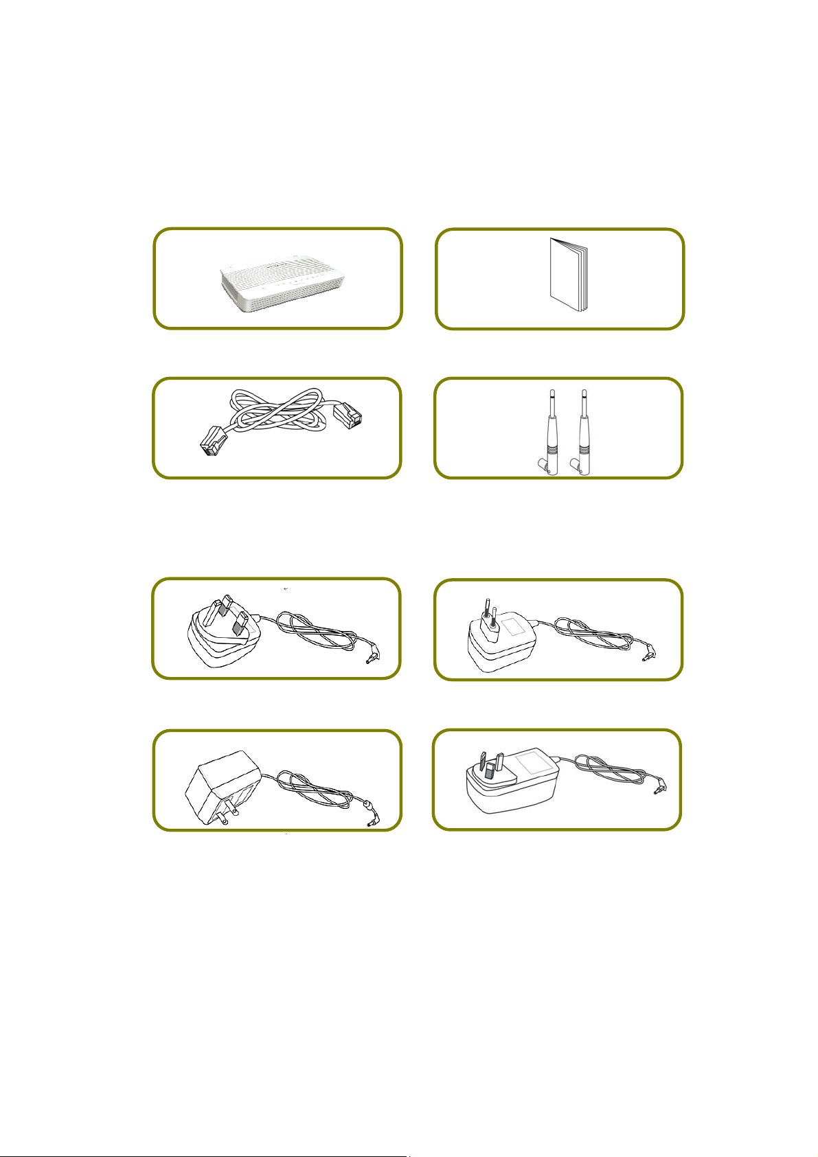
22.. PPaacckkaaggee CCoonntteenntt
Take a look at the package content. If there is anything missed or damaged,
please contact DrayTek or dealer immediately.
Vigor Router Quick Start Guide
RJ-45 Cat-5 Ethernet Cable Antenna (for “n” or “ac” model)
The type of the power adapter depends on the country that the router will be
installed. * The maximum power consumption is 17-23 Watt.
UK-type Power Adapter EU-type Power Adapter
USA/Taiwan-type Power Adapter AU/NZ-type Power Adapter
2
Page 10

33.. PPaanneell EExxppllaannaattiioonn
LED Status Explanation
Blinking The router is powered on and running normally.
(Activity)
USB
~
WLAN
WAN
~
LAN1/2/3/4
Blinking When ACT and WLAN LEDs blink quickly and
simultaneously is enabled and the system waits for
wireless station of connection.
Off The router is powered off.
On A USB device is connected and active.
Blinking The data is transmitting.
On Wireless access point is ready.
Blinking Ethernet packets are transmitting over wireless LAN.
Blinking When ACT and WLAN LEDs blink quickly and
simultaneously is enabled and the system waits for
wireless station of connection.
Off The WLAN function is inactive.
On Internet connection is ready.
Blinking The data is transmitting.
Off Internet connection is not ready.
On
Blinking The data is transmitting through WAN port.
Off The WAN port is disconnected.
The WAN port is connected with Ethernet cable.
On The LAN port is connected.
Blinking The data is transmitting.
Off The LAN port is disconnected.
3
Page 11

Interface Description
Wireless LAN
ON/OFF/WPS
WLAN On - Press the button and release it within 2 seconds. When
the wireless function is ready, the green LED will be on.
WLAN Off - Press the button and release it within 2 seconds to turn
off the WLAN function. When the wireless function is not ready, the
LED will be off.
WPS - When WPS function is enabled by web user interface, press
this button for mor e th an 2 seconds to wait for client’s device making
network connection through WPS.
Factory Reset Restore the default settings.
Usage: Turn on the router (ACT LED is blinking). Press the hole and
keep for more than 5 seconds. When you see the ACT LED begins to
blink rapidly than usual, release the button. Then the router will
restart with the factory default configuration.
USB1~USB2 Connector for a USB device (for 3G/4G USB Modem or printer).
GigaLAN1~LAN4 Connectors for local networked devices.
WAN Connector for remote networked devices.
ON/OFF Power Switch.
PWR Connector for a power adapter.
4
Page 12

44.. HHaarrddwwaarree IInnssttaallllaattiioonn
This section will guide you to install the router through hardware connection and
configure the router’s settings through web browser.
Before starting to configure the router (taking Vigor2133n for example), you
have to connect your devices correctly.
44..11 NNeettwwoorrkk CCoonnnneeccttiioonn
1. Connect the cable Modem/DSL Modem/Media Converter to any WAN port of
router with Ethernet cable (RJ-45).
2. Connect one port of 4-port switch to your computer with a RJ-45 cable. This
device allows you to connect 4 PCs directly.
3. Connect detachable antennas to the router.
4. Connect one end of the power cord to the power port of this device.
Connect the other end to the wall outlet of electricity.
5. Power on the router.
6. Check the ACT and WAN, LAN LEDs to assure network connection.
(For the detailed information of LED status, please refer to section 3. Panel
Explanation)
5
Page 13

44..22 WWaallll--MMoouunntteedd IInnssttaallllaattiioonn
Vigor2133 series has keyhole type mounting slots on the underside.
1. A template is provided on the Vigor2133 packaging box to enable you to
space the screws correctly on the wall.
2. Place the template on the wall and drill the holes according to the
recommended instruction.
3. Fit screws into the wall using the appropriate type of wall plug.
Note
The recommended drill diameter shall be 6.5mm (1/4”).
4. When you finished about procedure, the router has been mounted on the
wall firmly.
6
Page 14

55.. SSooffttwwaarree CCoonnffiigguurraattiioonn
To access Internet, please finish basic configuration after completing the
hardware installation.
The Quick Start Wizard is designed for you to easily set up your router for
Internet access. You can directly access the Quick Start Wizard via Web
Configurator.
1. Make sure your PC connects to the router correctly.
Note You may either simply set up your computer to get IP dynamically
from the router or set up the IP address of the computer to be the
same subnet as the default IP address of Vigor router
192.168.1.1. For the detailed information, please refer to the
section - Trouble Shooting in the User’s Guide.
2. Open a web browser on your PC and type http://192.168.1.1. A pop-up
window will open to ask for username and password. Please type
“admin/admin” as the Username/Password and click Login.
7
Page 15

3. Now, the Main Screen will pop up. Click Wizards>>Quick Start Wizard.
Note The home page will change slightly in accordance with the router
you have.
4. Enter the login password on the field of New Password and retype it on the
field of Confirm Password. Then click Next to continue.
8
Page 16
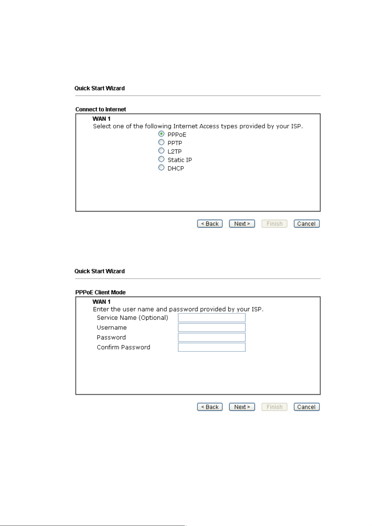
5. On the next page as shown below, please select the appropriate protocol
according to the information from your ISP. For example, you should
select PPPoE mode if the ISP provides you PPPoE interface. Then click Next
for next step.
PPPoE: If you click PPPoE as the protocol, after clicking Next, you will get
the following web page. Please manually enter the Username/Password
provided by your ISP. Then click Next.
9
Page 17
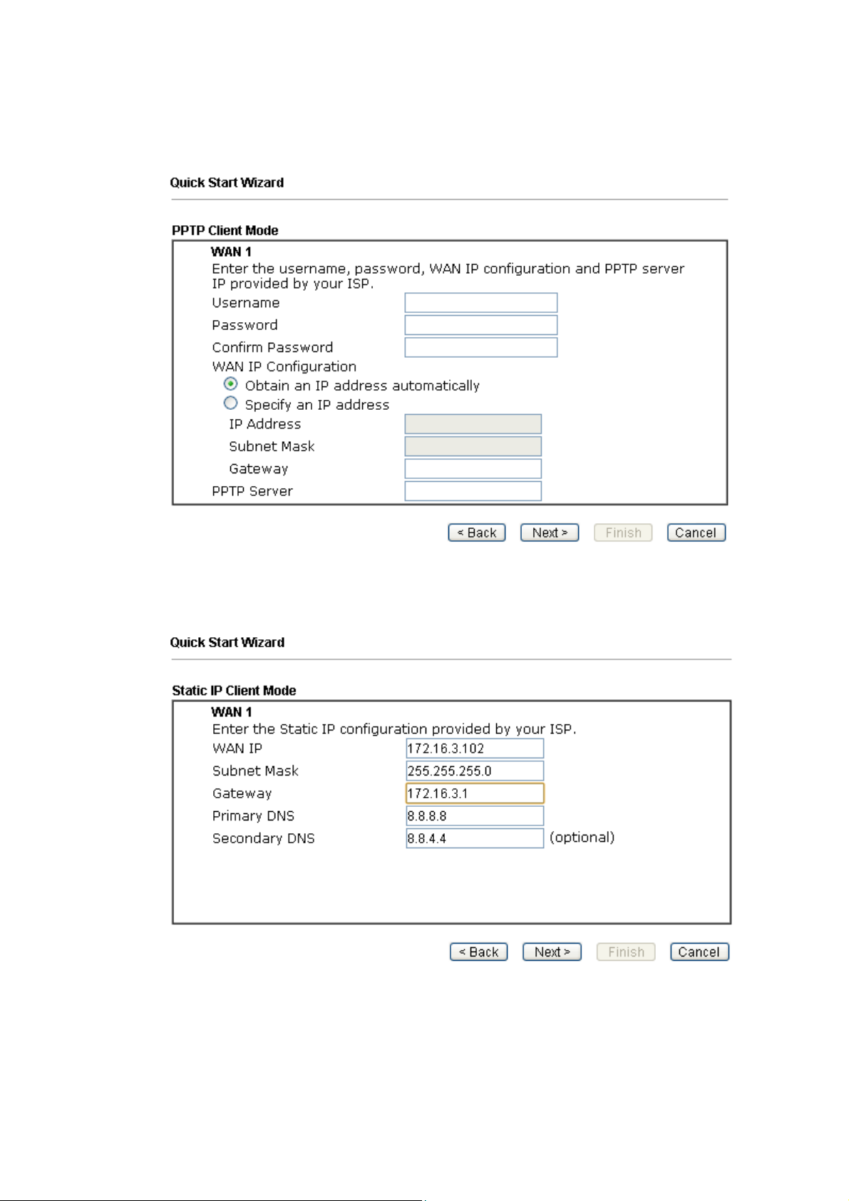
PPTP/L2TP: if you click PPTP/L2TP, you will get the following page. Please
type in all the information originally provided by your ISP. Then click Next
for next step.
Static IP: if you click Static IP, you will get the following page. Please type in
the IP address information originally provided by your ISP. Then click Next
for next step.
10
Page 18
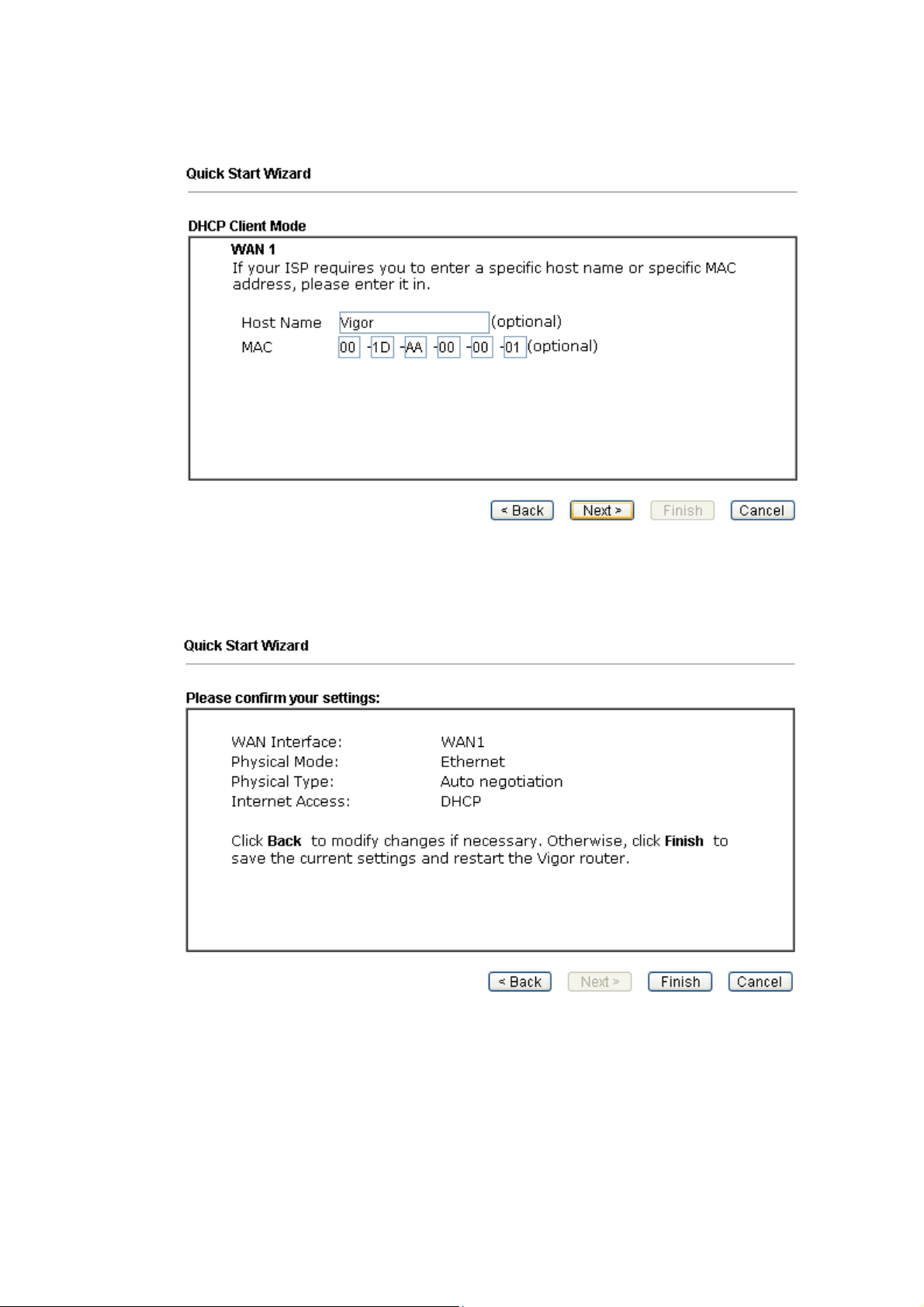
DHCP: if you click DHCP, you will get the following page. Simply click Next
to continue.
6. Now you can see the following screen. It indicates that the setup is complete.
Different types of connection modes will have different summary. Click
Finish and then restart the router. Afterward, you will enjoy surfing on the
Internet.
66.. CCuussttoommeerr SSeerrvviiccee
If the router cannot work correctly after trying many efforts, please contact your
dealer/DrayTek for further help right away. For any questions, please feel free
to send e-mail to support@draytek.com.
11
 Loading...