

Page 1

Page 2

Vigor2130 Series
High Speed Gigabit Router
User’s Guide
Version: 1.0
Date: 31/08/2009
ii
Vigor2130 Series User’s Guide
Page 3

Copyright Information
Copyright
Declarations
Trademarks
Copyright 2009 All rights reserved. This publication contains information that is
protected by copyright. No part may be reproduced, transmitted, transcribed, stored in a
retrieval system, or translated into any language without written permission from the
copyright holders.
The following trademarks are used in this document:
z Microsoft is a registered trademark of Microsoft Corp.
z Windows, Windows 95, 98, Me, NT, 2000, XP, Vista and Explorer are
trademarks of Microsoft Corp.
z Apple and Mac OS are registered trademarks of Apple Inc.
z Other products may be trademarks or registered trademarks of their respective
manufacturers.
Safety Instructions and Approval
Safety
Instructions
Warranty
z Read the installation guide thoroughly before you set up the router.
z The router is a complicated electronic unit that may be repaired only be
authorized and qualified personnel. Do not try to open or repair the router
yourself.
z Do not place the router in a damp or humid place, e.g. a bathroom.
z The router should be used in a sheltered area, within a temperature range of +5 to
+40 Celsius.
z Do not expose the router to direct sunlight or other heat sources. The housing and
electronic components may be damaged by direct sunlight or heat sources.
z Do not deploy the cable for LAN connection outdoor to prevent electronic shock
hazards.
z Keep the package out of reach of children.
z When you want to dispose of the router, please follow local regulations on
conservation of the environment.
We warrant to the original end user (purchaser) that the router will be free from any
defects in workmanship or materials for a period of two (2) years from the date of
purchase from the dealer. Please keep your purchase receipt in a safe place as it serves
as proof of date of purchase. During the warranty period, and upon proof of purchase,
should the product have indications of failure due to faulty workmanship and/or
materials, we will, at our discretion, repair or replace the defective products or
components, without charge for either parts or labor, to whatever extent we deem
necessary tore-store the product to proper operating condition. Any replacement will
consist of a new or re-manufactured functionally equivalent product of equal value, and
will be offered solely at our discretion. This warranty will not apply if the product is
modified, misused, tampered with, dam a ged by an act of God, or subjected to abnormal
working conditions. The warranty does not cover the bundled or licensed software of
other vendors. Defects which do not significantly affect the usability of the product will
not be covered by the warranty. We reserve the right to re vi se the m a nual and onli ne
documentation and to make changes from time to time in the contents hereof without
obligation to notify any person of such revision or changes.
Be a Registered
Owner
Firmware & Tools
Updates
Vigor2130 Series User’s Guide
Web registration is preferred. You can register your Vigor router via
http://www.draytek.com.
Due to the continuous evolution of DrayTek technology, all routers will be regularly
upgraded. Please consult the DrayTek web site for more information on newest
firmware, tools and documents.
http://www.draytek.com
iii
Page 4

European Community Declarations
Manufacturer: DrayTek Corp.
Address: No. 26, Fu Shing Road, HuKou County, HsinChu Industrial Park, Hsin-Chu, Taiwan 303
Product: Vigor2130 Series Router
DrayTek Corp. declares that Vigor2130 Series of routers are in compliance with the following essential
requirements and other relevant provisions of R&TTE Directive 1999/5/EEC.
The product conforms to the requirements of Electro-Magnetic Compatibility (EMC) Directive 2004/108/EC by
complying with the requirements set forth in EN55022/Class B and EN55024/Class B.
The product conforms to the requirements of Low Voltage (LVD) Directive 2006/95/EC by complying with the
requirements set forth in EN60950-1.
Regulatory Information
Federal Communication Commission Interference Statement
This equipment has been tested and found to comply with the limits for a Class B digital device, pursuant to Part
15 of the FCC Rules. These limits are designed to provide reasonable protection against harmful interference in a
residential installation. This equipment generates, uses and can radiate radio frequency energy and, if not installed
and used in accordance with the instructions, may cause harmful interference to radio communications. However,
there is no guarantee that interference will not occur in a particular installation. If this equipment does cause
harmful interference to radio or televisio n recept i on , whi ch can be determined by turning the equipment of f a nd
on, the use is encouraged to try to correct the interference by one of the following measures:
z Reorient or relocate the receiving antenna.
z Increase the separation between the equipment and receiver.
z Connect the equipment into an outlet on a circuit different form that to which the receiver is connected.
z Consult the dealer or an experienced radio/TV technician for help.
This device complies with Part 15 of the FCC Rules. Operation is subject to the following two conditions:
(1) This device may not cause harmful interference, and
(2) This device may accept any interference received, including interference that may cause undesired operation.
Please visit http://www.draytek.com/user/AboutRegulatory.php
This product is designed for 2.4GHz WLAN network throughout the EC region and Switzerland with restrictions
in France. Please see the user manual for the applicable networks on your product.
iv
Vigor2130 Series User’s Guide
Page 5

TTaabbllee ooff CCoonntteennttss
1
Preface ...............................................................................................................1
1.1 Web Configuration Buttons Explanation................................................................................. 1
1.2 LED Indicators and Connectors.............................................................................................. 2
1.2.1 For Vigor2130................................................................................................................... 2
1.2.2 For Vigor2130n................................................................................................................. 4
1.2.3 For Vigor2130Vn............................................................................................................... 6
1.3 Hardware Installation .............................................................................................................. 8
Stand Installation....................................................................................................................... 9
1.4 Printer Installation ................................................................................................................. 10
2
Configuring Basic Settings ............................................................................15
2.1 Two-Level Management........................................................................................................15
2.2 Accessing Web Page............................................................................................................ 15
3
2.3 Changing Password.............................................................................................................. 16
2.4 Quick Start Wizard................................................................................................................ 18
2.4.1 Setting up the Password................................................................................................. 18
2.4.2 Setting up the Time Zone............................................................................................... 19
2.4.3 Setting up the Internet Connection................................................................................. 19
2.4.4 Setting up the Wireless Connection ............................................................................... 24
2.4.5 Save the Wizard Configuration....................................................................................... 29
2.5 Online St atus......................................................................................................................... 29
2.6 Saving Configuration............................................................................................................. 30
U s e r M o d e O p e r a t i o n............................................................................................31
3.1 WAN...................................................................................................................................... 31
3.1.1 Internet Access............................................................................................................... 33
3.1.2 Ports................................................................................................................................ 39
3.1.3 3G Backup...................................................................................................................... 40
3.2 LAN ....................................................................................................................................... 41
3.2.1 General Setup................................................................................................................. 43
3.2.2 Ports................................................................................................................................ 44
3.2.3 MAC Address Table........................................................................................................ 45
3.2.4 VLAN............................................................................................................................... 46
3.2.5 Static Route.................................................................................................................... 47
3.2.6 Bind IP to MAC............................................................................................................... 49
3.3 NAT ....................................................................................................................................... 50
3.3.1 Hardware NAT................................................................................................................ 51
3.3.2 Open Ports...................................................................................................................... 51
Vigor2130 Series User’s Guide
v
Page 6

3.3.3 DMZ Host........................................................................................................................ 53
3.4 Bandwidth Management....................................................................................................... 54
3.4.1 Session Limit .................................................................................................................. 54
3.4.2 Bandwidth Limit .............................................................................................................. 55
3.4.3 Port Rate Control............................................................................................................ 56
3.4.4 QoS Control List ............................................................................................................. 57
3.4.5 Ports Priority................................................................................................................... 61
3.4.6 QoS Statistics................................................................................................................. 62
3.5 Applications........................................................................................................................... 65
3.5.1 Dynamic DNS................................................................................................................. 65
3.5.2 Schedule......................................................................................................................... 66
3.5.3 IGMP Snooping ..............................................................................................................67
3.5.4 IGMP Status ................................................................................................................... 68
3.5.5 UPnP Configuration........................................................................................................68
3.6 Wireless LAN ........................................................................................................................ 70
3.6.1 Basic Concepts............................................................................................................... 70
3.6.2 General Setup................................................................................................................. 71
3.6.3 Access Control................................................................................................................ 76
3.6.4 Station List...................................................................................................................... 77
3.6.5 Access Point Discovery.................................................................................................. 78
4
3.7 USB Application.................................................................................................................... 78
3.7.1 USB General Settings..................................................................................................... 78
3.7.2 FTP User Management .................................................................................................. 79
3.7.3 Disk Status...................................................................................................................... 80
3.7.4 Disk Shares .................................................................................................................... 80
3.8 User....................................................................................................................................... 82
3.8.1 User Configuration.......................................................................................................... 82
3.9 System Maintenance............................................................................................................. 83
3.9.1 System Status................................................................................................................. 83
3.9.2 User Password ............................................................................................................... 85
3.9.3 Configuration Backup .....................................................................................................85
3.9.4 Syslog / Mail Alert...........................................................................................................87
3.9.5 Time and Date................................................................................................................ 89
3.9.6 Management................................................................................................................... 90
3.9.7 Reboot System............................................................................................................... 90
3.9.8 Firmware Upgrade..........................................................................................................91
A d m i n M o d e O p e r a t i o n.........................................................................................93
4.1 WAN...................................................................................................................................... 93
4.1.1 Internet Access............................................................................................................... 95
4.1.2 Ports.............................................................................................................................. 100
4.1.3 3G Backup.................................................................................................................... 101
4.2 LAN ..................................................................................................................................... 102
4.2.1 General Setup............................................................................................................... 104
4.2.2 Ports.............................................................................................................................. 105
4.2.3 MAC Address Table...................................................................................................... 107
4.2.4 VLAN............................................................................................................................. 108
4.2.5 Static Route.................................................................................................................. 109
4.2.6 Bind IP to MAC............................................................................................................. 111
vi
Vigor2130 Series User’s Guide
Page 7

4.3 NAT ......................................................................................................................................112
4.3.1 Hardware NAT..............................................................................................................113
4.3.2 Open Ports.................................................................................................................... 113
.3.3 DMZ Host........................................................................................................................ 115
4.4 Firewall.................................................................................................................................116
4.4.1 DoS Defense ................................................................................................................ 116
4.4.2 Ports Configuration....................................................................................................... 117
4.4.3 Rate Control Object...................................................................................................... 119
4.4.4 Access Control List....................................................................................................... 120
4.5 Bandwidth Management ..................................................................................................... 136
.5.1 Session Limit .................................................................................................................. 137
4.5.2 Bandwidth Limit ............................................................................................................138
4.5.3 Port Rate Control.......................................................................................................... 139
4.5.4 QoS Control List ........................................................................................................... 139
4.5.5 Ports Priority................................................................................................................. 144
4.5.6 QoS Statistics............................................................................................................... 145
4.6 Applications.........................................................................................................................148
4.6.1 Dynamic DNS............................................................................................................... 148
4.6.2 Schedule....................................................................................................................... 149
4.6.3 IGMP Snooping ............................................................................................................150
4.6.4 IGMP Status ................................................................................................................. 151
4.6.5 UPnP Configuration...................................................................................................... 151
4.7 VPN and Remote Access.................................................................................................... 153
4.7.1 Remote Access Control................................................................................................ 153
4.7.2 PPTP Remote Dial-in.................................................................................................... 154
4.7.3 IPSec Remote Dial-in ................................................................................................... 156
4.7.4 Remote Dial-in Status................................................................................................... 158
4.7.5 LAN to LAN................................................................................................................... 159
4.8 Wireless LAN ...................................................................................................................... 161
4.8.1 Basic Concepts............................................................................................................. 161
4.8.2 General Setup............................................................................................................... 163
4.8.3 Access Control.............................................................................................................. 167
4.8.4 Station List.................................................................................................................... 168
4.8.5 Access Point Discovery................................................................................................ 169
4.9 USB Application.................................................................................................................. 169
4.9.1 USB General Settings................................................................................................... 170
4.9.2 FTP User Management ................................................................................................ 170
4.9.3 Disk Status.................................................................................................................... 171
4.9.4 Disk Shares .................................................................................................................. 171
4.10 User................................................................................................................................... 173
4.10.1 User Configuration...................................................................................................... 173
4.11 System Maintenance......................................................................................................... 175
4.11.1 System Status............................................................................................................. 175
4.11.2 System Password....................................................................................................... 176
4.11.3 User Password ........................................................................................................... 176
4.11.4 Configuration Backup ................................................................................................. 177
4.11.5 Syslog/Mail Alert.........................................................................................................178
4.11.6 Time and Date............................................................................................................ 180
4.11.7 Management............................................................................................................... 181
4.11.8 Reboot System........................................................................................................... 181
4.11.9 Firmware Upgrade...................................................................................................... 182
Vigor2130 Series User’s Guide
vii
Page 8

4.12 Diagnostics........................................................................................................................ 183
4.12.1 Ping............................................................................................................................. 183
4.12.2 Routing Table ............................................................................................................. 184
4.12.3 System Log................................................................................................................. 185
4.12.4 Traffic Overview.......................................................................................................... 185
4.12.5 Detailed Statistics....................................................................................................... 186
4.12.6 MAC Address Table.................................................................................................... 188
4.12.7 DHCP Table................................................................................................................ 190
4.12.8 Data Flow Monitor....................................................................................................... 191
4.12.9 Ports State.................................................................................................................. 192
5
Trouble Shooting...........................................................................................193
5.1 Checking If the Hardware Status Is OK or Not....................................................................193
5.2 Checking If the Network Connection Settings on Your Computer Is OK or Not................. 194
5.3 Pinging the Router from Your Computer............................................................................. 196
5.4 Checking If the ISP Settings are OK or Not........................................................................ 197
5.5 Backing to Factory Default Setting If Necessary ................................................................ 199
5.6 Contacting Your Dealer....................................................................................................... 200
viii
Vigor2130 Series User’s Guide
Page 9
1
Prreeffaaccee
P
The Vigor2130 series are the routers with high speed in data transmission through WAN port
and LAN ports. With hardware NAT acceleration, the rate of Vigor2130 series can be greater
than 900Mbps almost.
With the development of NGN (Next Generation Network), you may recently hear the news
about FTTx deployment in your local area or even have already subscribed the unbundling last
mile service (e.g. VDSL2) from local ITSP for FTTx. As adopting FTTx, the main question
for end users is whether your legacy router could fully utilize its bandwidth or not.
For example, you purchase a 120 Mbps Internet connection from your ISP but your existing
router cannot support 90 Mbps throughput. That’s why DrayTek launches Vigor 2130 series –
High speed Gigabit router, perfectly complied with VDSL2 environment including Vigor2130,
Vigor2130n and Vigor2130Vn for speed-wanted customers. With high throughput
performance and secured broadband connectivity provided by Vigor 2130 series, you can
simultaneously engage these bandwidth-intensive applications, such as high-definition video
streaming, online gaming, and Internet telephony / access.
11..11 WWeebb CCoonnffiigguurraattiioonn BBuuttttoonnss EExxppllaannaattiioonn
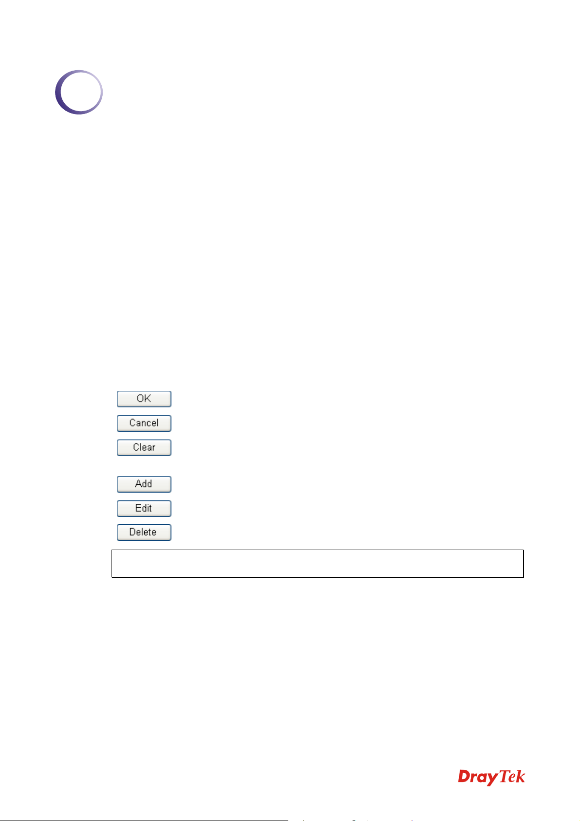
Several main buttons appeared on the web pages are defined as the following:
Save and apply current settings.
Cancel current settings and recover to the previous saved settings.
Clear all the selections and parameters settings, including selection from
drop-down list. All the values must be reset with factory default settings.
Add new settings for specified item.
Edit the settings for the selected item.
Delete the selected item with the corresponding settings.
Note: For the other buttons shown on the web pages, please refer to Chapter 4 for detailed
explanation.
Vigor2130 Series User’s Guide
1
Page 10
11..22 LLEEDD IInnddiiccaattoorrss aanndd CCoonnnneeccttoorrss
Before you use the Vigor router, please get acquainted with the LED indicators and connectors
first.
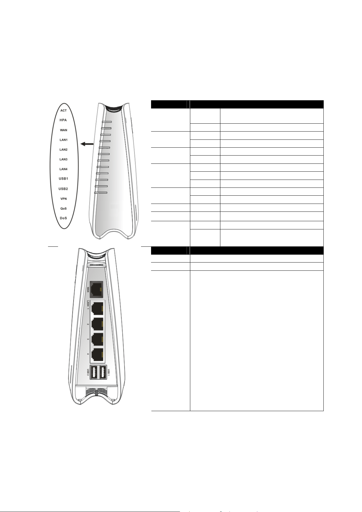
11..22..11 FFoorr VViiggoorr22113300
LED Status Explanation
ACT
(Activity)
LAN1/2/3/4
VPN On The VPN tunnel is active.
QoS
DoS
Blinking The router is powered on and running
Off The router is powered off.
On Hardware NAT is enabled. HPA
Off Hardware NAT is disabled.
On The WAN port is connected. WAN
Blinking It will blink while transmitting data.
On The port is connected.
Off The port is disconnected.
Blinking The data is transmitting.
On A USB device is connected and active.USB1/2
Blinking The data is transmitting.
On The QoS function is active.
On The DoS/DDoS function is active.
Blinking It will blink while detecting an attack.
normally.
Interface Description
WAN Connector for accessing the Internet.
LAN (1-4) Connectors for local networked devices.
USB Connector for USB storage device (Pen
Driver/Mobile HD) or printer or 3G backup.
2
Vigor2130 Series User’s Guide
Page 11

Interface Description
Factory Reset Restore the default settings. Usage: Turn on the router (ACT LED is blinking). Press
the hole and keep for more than 5 seconds. When you see the ACT LED begins to
blink rapidly than usual, release the button. Then the router will restart with the
factory default configuration.
PWR Connector for a power adapter.
ON/OFF
Power Switch.
Vigor2130 Series User’s Guide
3
Page 12
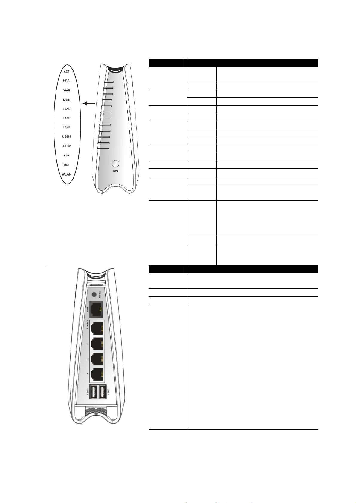
11..22..22 FFoorr VViiggoorr22113300nn
LED Status Explanation
ACT
(Activity)
LAN1/2/3/4
VPN On The VPN tunnel is active.
QoS
WPS Button
Interface Description
WLAN
WAN Connector for accessing the Internet.
LAN (1-4) Connectors for local networked devices.
USB Connector for USB storage (Pen Driver /Mobile
Blinking The router is powered on and running
normally.
Off The router is powered off.
On Hardware NAT is enabled. HPA
Off Hardware NAT is disabled.
On The WAN port is connected. WAN
Blinking It will blink while transmitting data.
On The port is connected.
Off The port is disconnected.
Blinking The data is transmitting.
On A USB device is connected and active.USB1/2
Blinking The data is transmitting.
On The QoS function is active.
On Wireless access point is ready. WLAN
Blinking It will blink while wireless traffic goes
through.
On Press this button for 2 seconds to wait
for client device making network
connection through WPS. When the
LED lights up, the WPS connection
will be on.
Off The WPS is off.
Blinking Waiting for wireless client sending
requests for connection about two
minutes.
Press the button once to enable (WLAN LED on) or
disable (WLAN LED off) wireless connection.
HD) or printer.
4
Vigor2130 Series User’s Guide
Page 13

Interface Description
Factory Reset Restore the default settings. Usage: Turn on the router (ACT LED is blinking). Press
the hole and keep for more than 5 seconds. When you see the ACT LED begins to
blink rapidly than usual, release the button. Then the router will restart with the
factory default configuration.
PWR Connector for a power adapter.
ON/OFF
Power Switch.
Vigor2130 Series User’s Guide
5
Page 14
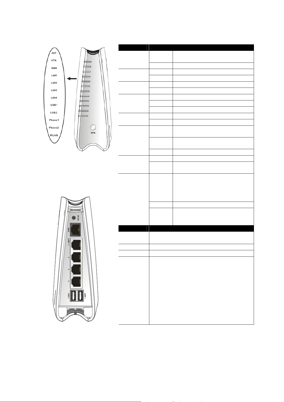
11..22..33 FFoorr VViiggoorr22113300VVnn
LED Status Explanation
ACT
(Activity)
LAN1/2/3/4
Phone1/
Phone2
WPS Button
Interface Description
WLAN
WAN Connector for accessing the Internet.
LAN (1-4) Connectors for local networked devices.
USB Connector for USB storage (Pen Driver/Mobile
Blinking The router is powered on and running
normally.
Off The router is powered off.
On Hardware NAT is enabled. HPA
Off Hardware NAT is disabled.
On The WAN port is connected. WAN
Blinking It will blink while transmitting data.
On The port is connected.
Off The port is disconnected.
Blinking The data is transmitting.
On A USB device is connected and active.USB1/2
Blinking The data is transmitting.
On The phone connected to this port is
off-hook.
Off The phone connected to this port is
on-hook.
Blinking A phone call comes.
On Wireless access point is ready. WLAN
Blinking It will blink while wireless traffic goes
through.
On Press this button for 2 seconds to wait
for client device making network
connection through WPS. When the
LED lights up, the WPS connection
will be on.
Off The WPS is off.
Blinking Waiting for wireless client sending
requests for connection about two
minutes.
Press the button once to enable (WLAN LED on) or
disable (WLAN LED off) wireless connection.
HD) or printer.
6
Vigor2130 Series User’s Guide
Page 15

Interface Description
Phone2/Phone1
Factory Reset Restore the default settings. Usage: Turn on the router (ACT LED is blinking). Press
PWR Connector for a power adapter.
ON/OFF
Connector of analog phone for VoIP communication
the hole and keep for more than 5 seconds. When you see the ACT LED begins to
blink rapidly than usual, release the button. Then the router will restart with the
factory default configuration.
Power Switch.
.
Vigor2130 Series User’s Guide
7
Page 16
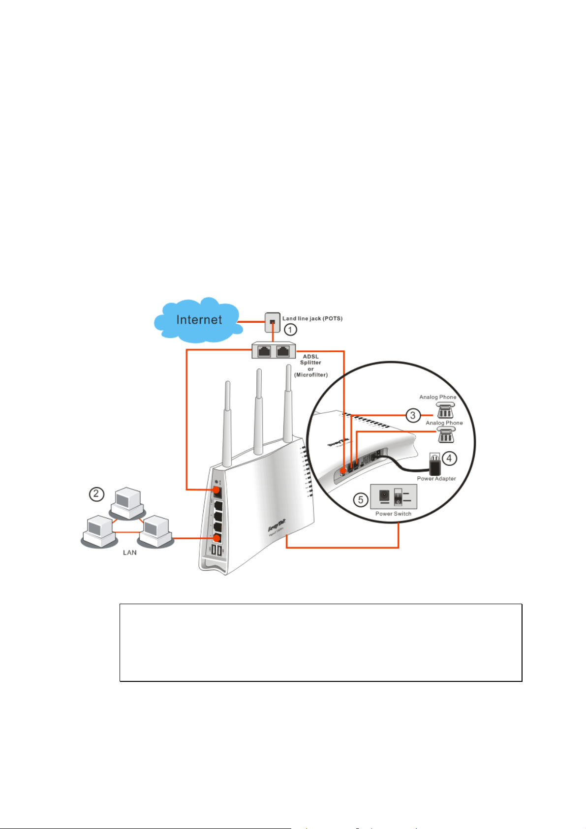
11..33 HHaarrddwwaarree IInnssttaallllaattiioonn
Before starting to configure the router, you have to connect your devices correctly.
1. Connect Line port to land line jack with a RJ-11 cable (Vn model).
2. Connect this device to a modem with an Ethernet cable.
3. Connect one port of 4-port switch to your computer with a RJ-45 cable. This device
allows you to connect 4 PCs directly.
4. Connect Phone port to a conventional analog telephone.
5. Connect detachable antennas to the router for Vigor2130 series (n model).
6. Connect one end of the power cord to the power port of this device. Connect the other
end to the wall outlet of electricity.
7. Power on the router.
8. Check the ACT and WAN, LAN LEDs to assure network connections.
(For the detailed information of LED status, please refer to section 1.1.)
Caution:
1. Each of the Phone ports can be connected to an analog phone only. Do not connect the
phone ports to the land line jack. Such connection might damage your router.
2. When the power is shutdown, VoIP phone will be disconnected. However, a phone set
connected to Phone 2 port can be used as the traditional telephone for the line will be
guided to land line jack via the router (loop through).
8
Vigor2130 Series User’s Guide
Page 17

SSttaanndd IInnssttaallllaattiioonn
The Vigor2130 must be placed erectly. Therefore you have to install a stand onto the router to
make it standing firmly. Please follow the figures listed below to finish the installation.
c
e f
d
Vigor2130 Series User’s Guide
9
Page 18
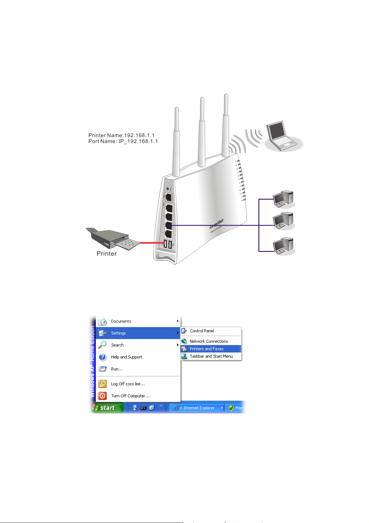
11..44 PPrriinntteerr IInnssttaallllaattiioonn
You can install a printer onto the router for sharing printing. All the PCs connected this router
can print documents via the router. The example provided here is made based on Windows
XP/2000. For Windows 98/SE/Vista, please visit www.draytek.com.
Before using it, please follow the steps below to configure settings for connected computers
(or wireless clients).
1. Connect the printer with the router through USB/parallel port.
2. Open Start->Settings-> Printer and Faxes.
3. Open File->Add a New Computer. A welcome dialog will appear. Please click Next.
10
Vigor2130 Series User’s Guide
Page 19

4. Click Local printer attached to this computer and click Next.
5. In this dialog, choose Create a new port Type of port and use the drop down list to
select Standard TCP/IP Port. Click Next.
Vigor2130 Series User’s Guide
11
Page 20

6. In the following dialog, type 192.168.1.1 (router’s LAN IP) in the field of Printer Name
or IP Address and type IP_192.168.1.1 as the port name. Then, click Next.
7. Click Standard and choose Generic Network Card.
8. Then, in the following dialog, click Finish.
12
Vigor2130 Series User’s Guide
Page 21

9. Now, your system will ask you to choose right name of the printer that you installed onto
the router. Such step can make correct driver loaded onto your PC. When you finish the
selection, click Next.
10. For the final stage, you need to go back to Control Panel-> Printers and edit the
property of the new printer you have added.
11. Select "LPR" on Protocol, type p1 (number 1) as Queue Name. Then click OK. Next
please refer to the red rectangle for choosing the correct protocol and UPR name.
Vigor2130 Series User’s Guide
13
Page 22
The printer can be used for printing now. Most of the printers with different manufacturers are
compatible with vigor router.
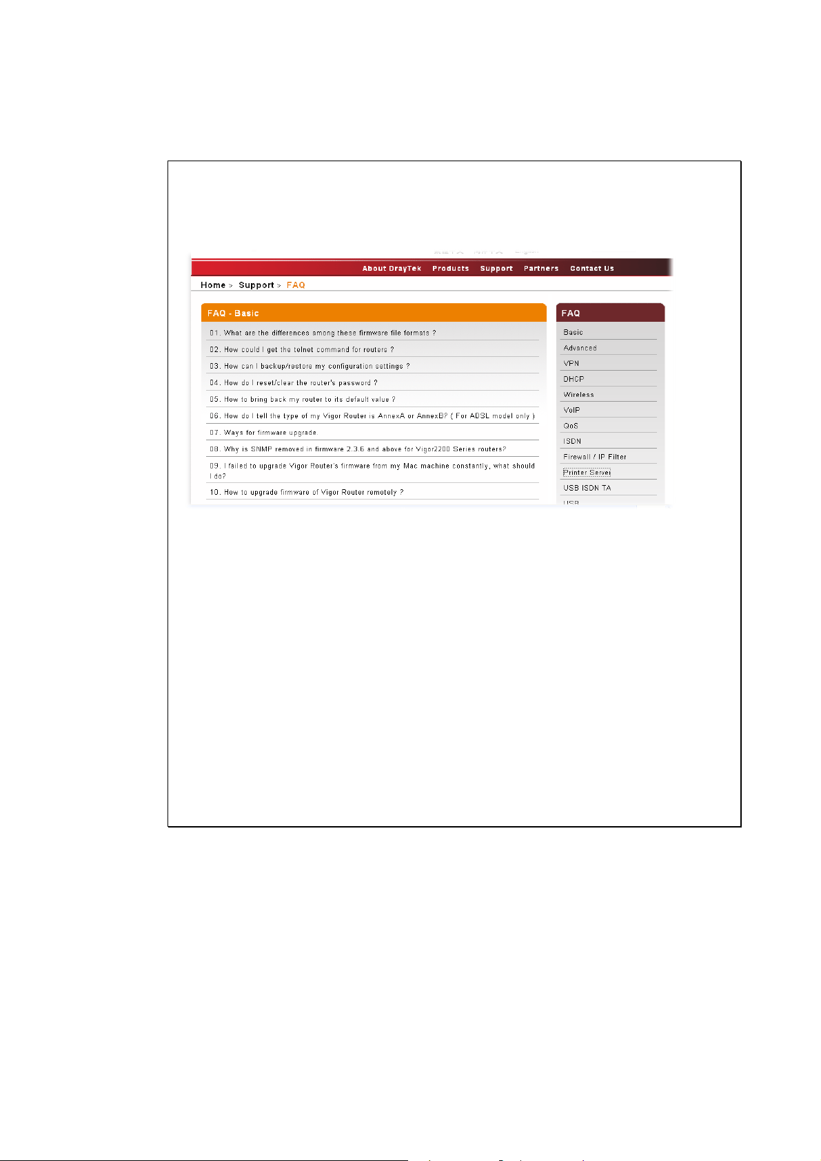
Note 1: Some printers with the fax/scanning or other additional functions are not
supported. If you do not know whether your printer is supported or not, please visit
www.draytek.com to find out the printer list. Open Support >FAQ; find out the link of
Printer Server and click it; then click the What types of printers are compatible with
Vigor router? link.
Note 2: Vigor router supports printing request from computers via LAN ports but not
WAN port.
14
Vigor2130 Series User’s Guide
Page 23
2
Coonnffiigguurriinngg
C
For using the router properly, it is necessary for you to change the password of web
configuration for security and adjust primary basic settings.
22..11 TTwwoo--LLeevveell MMaannaaggeemmeenntt
This chapter explains how to setup a password for an administrator/user and how to adjust
basic/advanced settings for accessing Internet successfully.
For user mode operation, do not type any word on the window and click Login for the simple
web pages for configuration. Yet, for admin mode operation, please type “admin/admin” on
Username/Password and click Login for full configuration.
22..22 AAcccceessssiinngg WWeebb PPaaggee
1. Make sure your PC connects to the router correctly.
Notice: You may either simply set up your computer to get IP dynamically
from the router or set up the IP address of the computer to be the same subnet as
the default IP address of Vigor router 192.168.1.1. For the detailed
information, please refer to the later section - Trouble Shooting of the guide.
Baassiicc
B
Seettttiinnggss
S
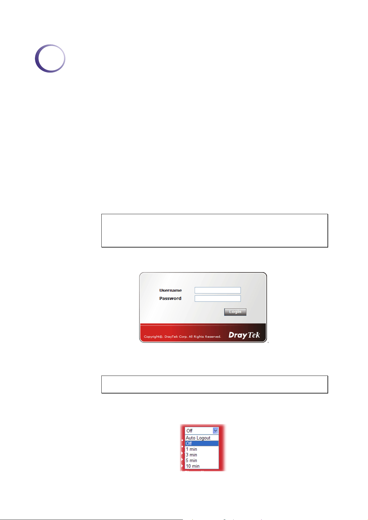
2. Open a web browser on your PC and type http://192.168.1.1. The following window
will be open to ask for username and password.
3. For user mode operation, do not type any word on the window and click Login for the
simple web pages for configuration. Yet, for admin mode operation, please type
“admin/admin” on Username/Password and click Login for full configuration.
Notice: If you fail to access to the web configuration, please go to “Trouble
Shooting” for detecting and solving your problem.
4. The web page can be logged out according to the chosen condition. The default setting is
Auto Logout, which means the web configuration system will logout after 5 minutes
without any operation. Change the setting for your necessity.
Vigor2130 Series User’s Guide
15
Page 24

22..33 CChhaannggiinngg PPaasssswwoorrdd
No matter user mode operation or admin mode operation, please change the password for the
original security of the router.
1. Open a web browser on your PC and type http://192.168.1.1. A pop-up window will
open to ask for username and password.
2. Please type “admin/admin” on Username/Password for admin mode. Otherwise, do not
type any word (both username and password are Null for user mode) on the window and
click Login on the window.
3. Now, the Main Screen will appear.
Main screen for admin mode operation (full configuration)
Main screen for user mode operation (simple configuration)
Note: The home page will change slightly in accordance with the type of the router
you have.
16
Vigor2130 Series User’s Guide
Page 25
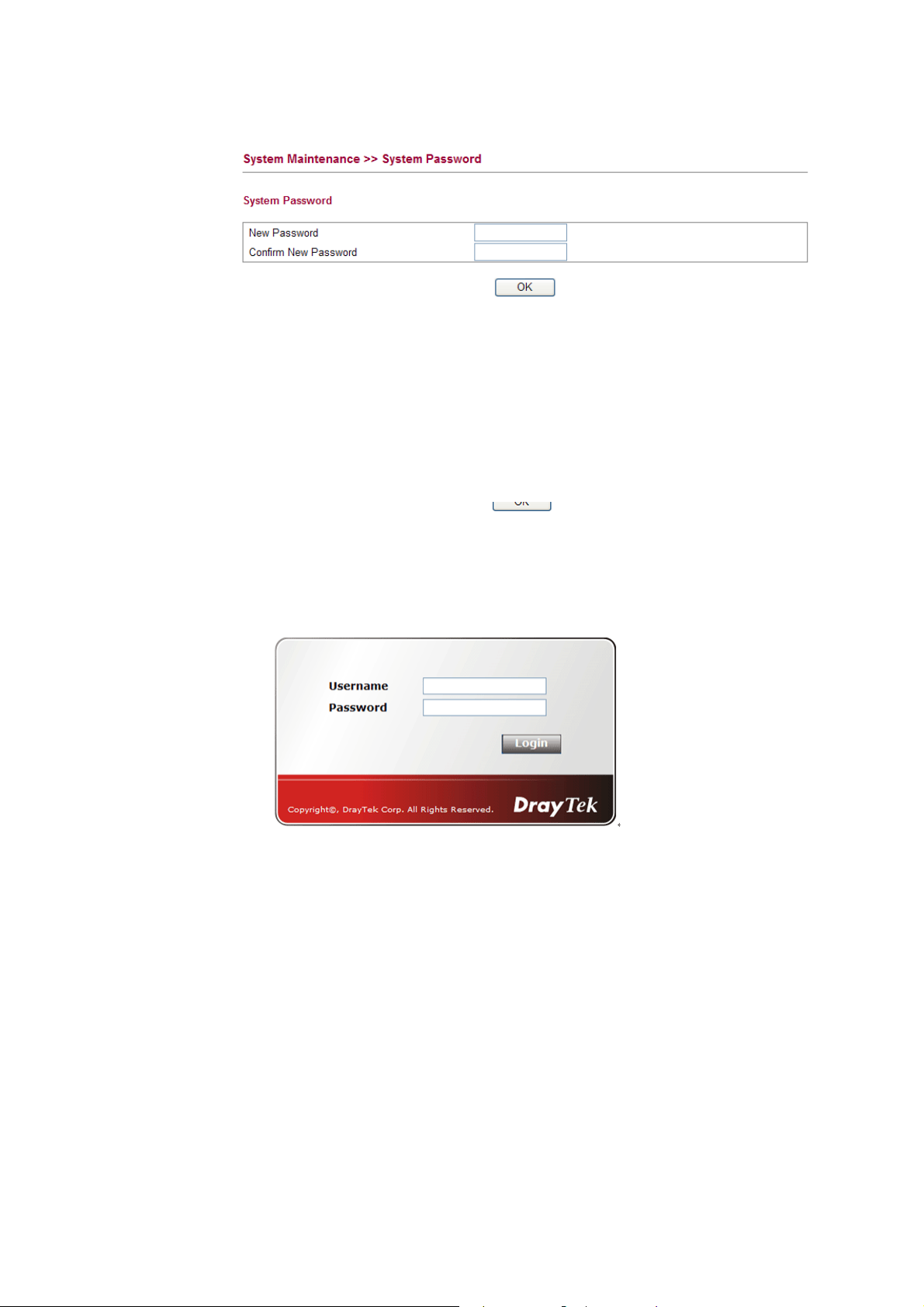
4. Go to System Maintenance page and choose System Password/User Password.
Or
5. Type New Password in New Password and Confirm New Password fields. Then click
OK to continue.
6. Now, the password has been changed. Next time, use the new password to access the
Web Configurator for this router.
Vigor2130 Series User’s Guide
17
Page 26
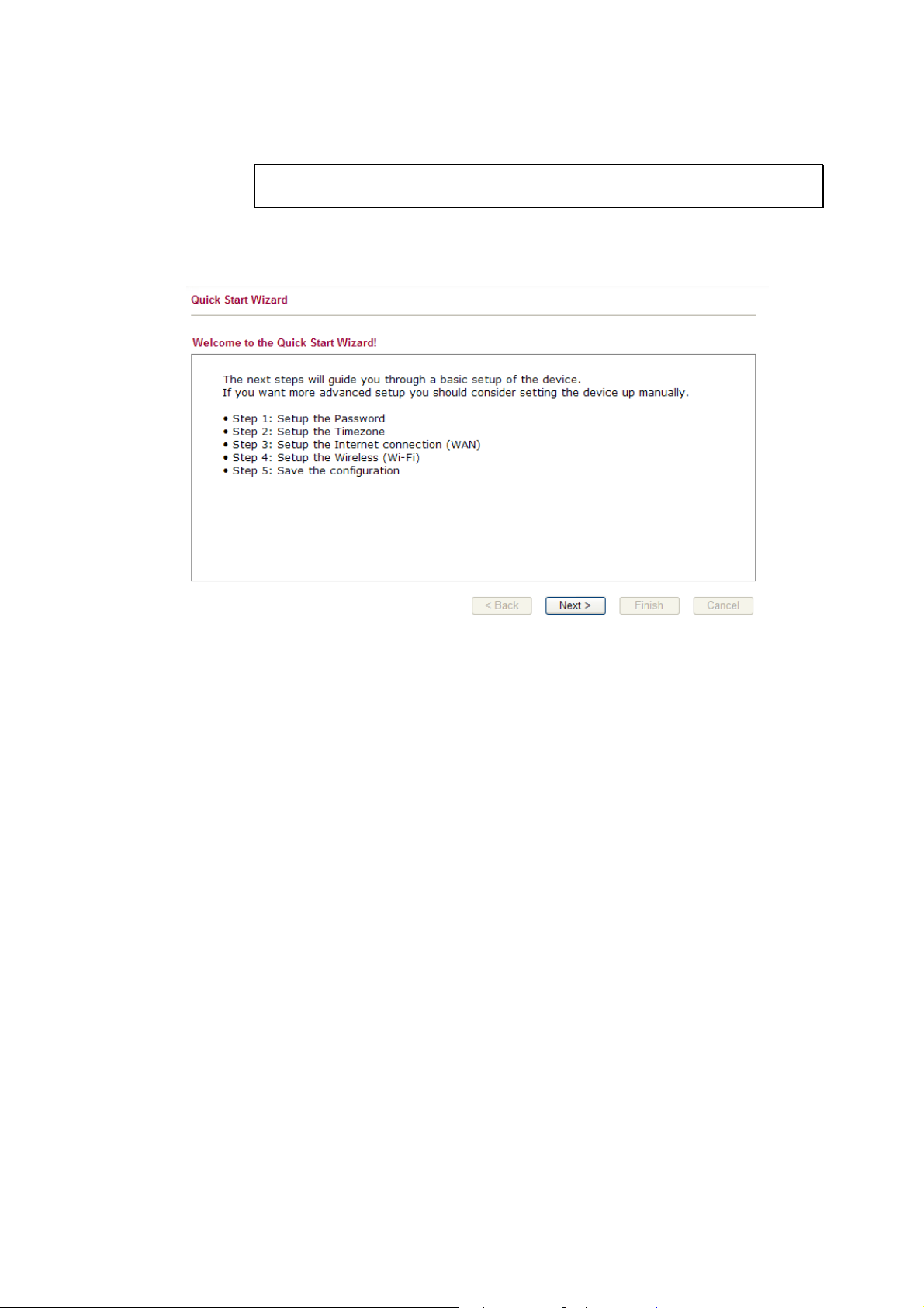
22..44 QQuuiicckk SSttaarrtt WWiizzaarrdd
Notice: Quick Start Wizard for user mode operation is the same as for admin
mode operation.
If your router can be under an environment with high speed NAT, the configuration provide
here can help you to deploy and use the router quickly. The first screen of Quick Start
Wizard is welcome page, please click Next.
22..44..11 SSeettttiinngg uupp tthhee PPaasssswwoorrdd
The first screen of Quick Start Wizard is entering login password. After typing the password,
please click Next.
18
Vigor2130 Series User’s Guide
Page 27

22..44..22 SSeettttiinngg uupp tthhee TTiimmee ZZoonnee
On the next page as shown below, please select the Time Zone for the router installed and
specify the NTP server(s). Then click Next for next step.
22..44..33 SSeettttiinngg uupp tthhee IInntteerrnneett CCoonnnneeccttiioonn
On the next page as shown below, please select the appropriate connection type according to
the information from your ISP. There are five types offered in this page. Each connection type
will bring out different web page.
Vigor2130 Series User’s Guide
19
Page 28
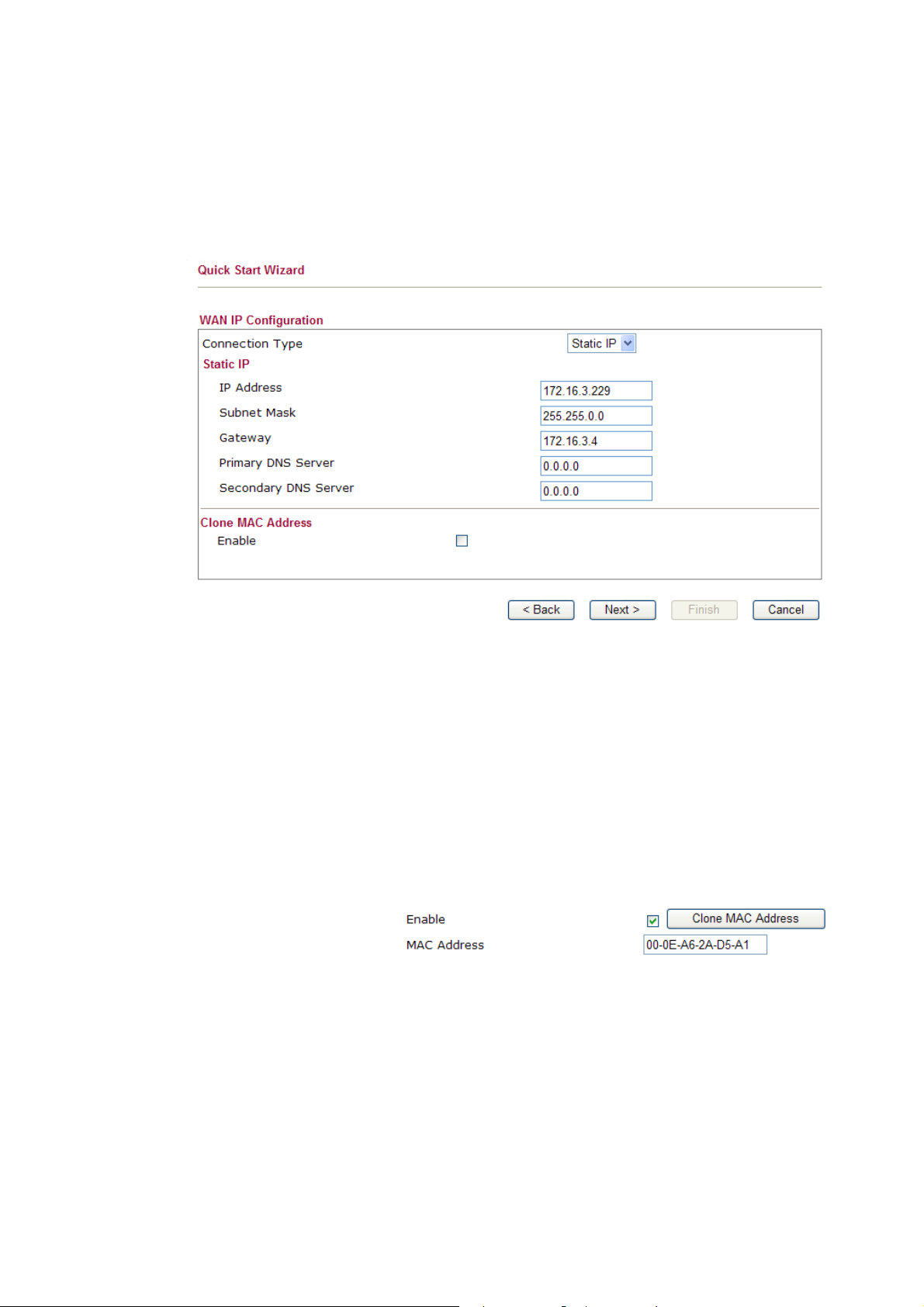
SSttaattiicc IIPP
You will receive a fixed public IP address or a public subnet, namely multiple public IP
addresses from your DSL or Cable ISP service providers. In most cases, a Cable service
provider will offer a fixed public IP, while a DSL service provider will offer a public subnet.
If you have a public subnet, you could assign an IP address or many IP address to the WAN
interface.
IP Address Type the IP address.
Subnet Mask Type the subnet mask.
Gateway Type the gateway IP address.
Primary DNS Server Type in the primary IP address for the router
Secondary DNS Server Type in secondary IP address for necessity in the future.
Enable The router will detect the MAC address automatically. Or,
check the box to enable MAC address cloning.
Clone MAC Address It is available when the box of Enable is checked. Click Clone
PC Address. The result will be displayed in the field of MAC
Address.
After finishing the settings here, please click Next.
20
Vigor2130 Series User’s Guide
Page 29
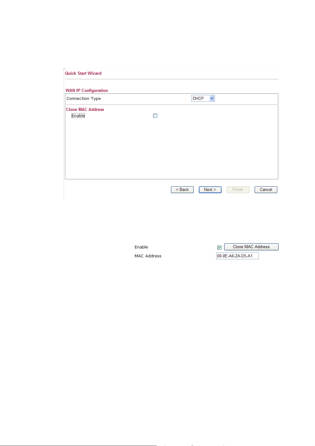
DDHHCCPP
It is not necessary for you to type any IP address manually. Simply choose this type and the
system will obtain the IP address automatically from DHCP server.
Enable The router will detect the MAC address automatically. Or,
check the box to enable MAC address cloning.
Clone MAC Address It is available when the box of Enable is checked. Click Clone
PC Address. The result will be displayed in the field of MAC
Address.
After finishing the settings here, please click Next.
PPPPPPooEE
PPPoE stands for Point-to-Point Protocol over Ethernet. It relies on two widely accepted
standards: PPP and Ethernet. It connects users through an Ethernet to the Internet with a
common broadband medium, such as a single DSL line, wireless device or cable modem. All
the users over the Ethernet can share a common connection.
PPPoE is used for most of DSL modem users. All local users can share one PPPoE connection
for accessing the Internet. Your service provider will provide you information about user name,
password, and authentication mode.
Vigor2130 Series User’s Guide
21
Page 30
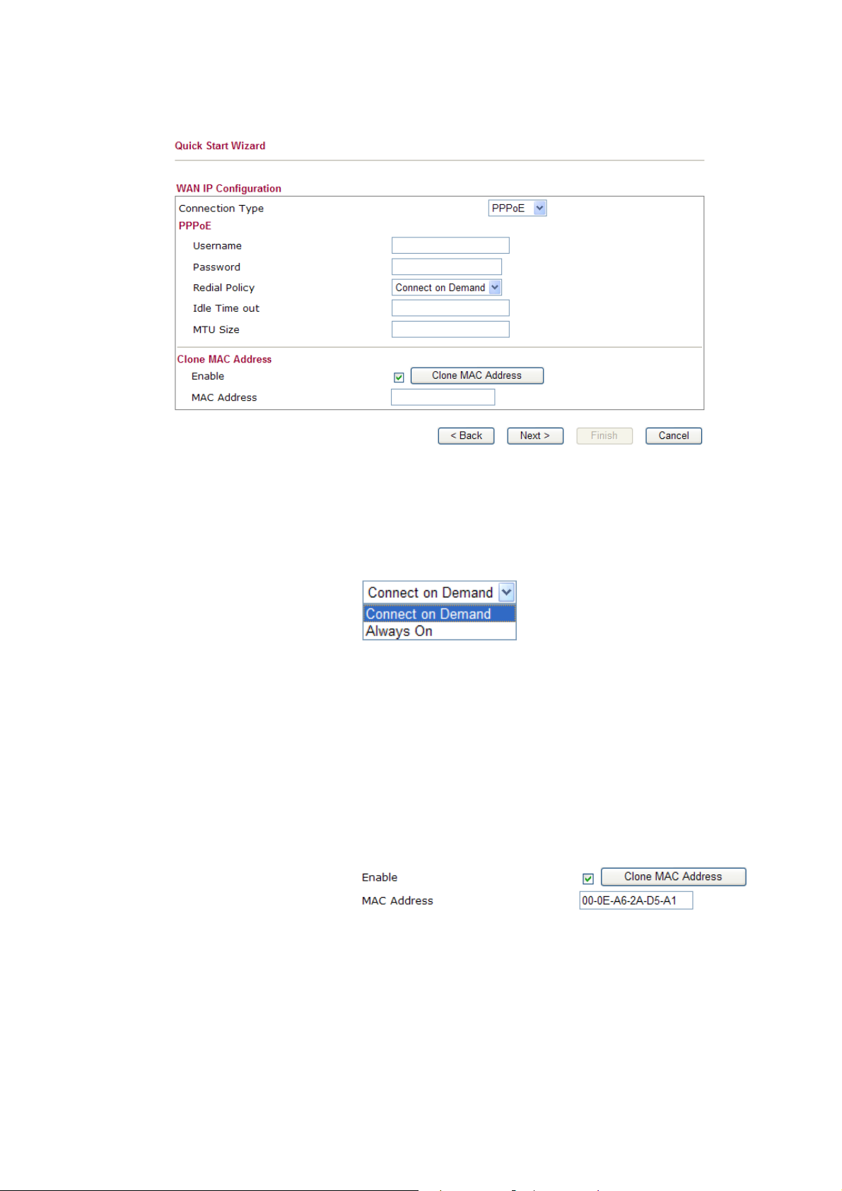
If your ISP provides you the PPPoE connection, please select PPPoE for this router. The
following page will be shown:
User Name Assign a specific valid user name provided by the ISP.
Password Assign a valid password provided by the ISP.
Redial Policy If you want to connect to Internet all the time, you can choose
Always On. Otherwise, choose Connect on Demand.
Idle Time Out Set the timeout for breaking down the Internet after passing
through the time without any action. The unit is seconds. The
range is XX ~ XX.
MTU Size
It means Max Transmit Unit for packet. The default
setting is 1442.
Enable The router will detect the MAC address automatically. Or,
check the box to enable MAC address cloning.
Clone MAC Address It is available when the box of Enable is checked. Click Clone
PC Address. The result will be displayed in the field of MAC
Address.
After finishing the settings here, please click Next.
22
Vigor2130 Series User’s Guide
Page 31

PPPPTTPP//LL22TTPP
if you click PPTP/L2TP as the protocol, please manually enter the Username/Password
provided by your ISP and all the required information.
User Name Assign a specific valid user name provided by the ISP.
Password Assign a valid password provided by the ISP.
Server Address Specify the IP address of the PPTP server.
WAN IP Network Settings You can choose Static IP or DHCP as WAN IP network setting.
IP Address Type the IP address if you choose Static IP as the WAN IP
network setting.
Subnet Mask Type the subnet mask if you chose Static IP as the WAN IP.
Redial Policy If you want to connect to Internet all the time, you can choose
Always On. Otherwise, choose Connect on Demand.
Idle Time Out Set the timeout for breaking down the Internet after passing
through the time without any action. The unit is seconds. The
range is XX ~ XX.
MTU Size
It means Max Transmit Unit for packet. The default
setting is 1442.
Enable The router will detect the MAC address automatically. Or,
Vigor2130 Series User’s Guide
check the box to enable MAC address cloning.
23
Page 32

Clone MAC Address It is available when the box of Enable is checked. Click Clone
PC Address. The result will be displayed in the field of MAC
Address.
After finishing the settings here, please click Next.
22..44..44 SSeettttiinngg uupp tthhee WWiirreelleessss CCoonnnneeccttiioonn
Now, you have to set up the wireless connection. For the user of Vigor2130, please skip this
step.
Enable Wireless LAN Check the box to enable the wireless function.
SSID Broadcast Choose Show to make the SSID being seen by wireless clients.
Choose Hide to prevent from wireless sniffing and make it
harder for unauthorized clients or STAs to join your wireless
LAN.
SSID It means the identification of the wireless LAN. SSID can be
any text numbers or various special characters. The default
SSID is "DrayTek". We suggest you to change it.
Wireless Mode Choose the wireless mode for this router. At present, only
802.11B/B/N mix is available.
Country Region Code Use the drop down list to choose the one that this router
supports.
Channel It means the channel of frequency of the wireless LAN. The
default channel is 11. You may switch channel if the selected
channel is under serious interference. If you have no idea of
choosing the frequency, please select Auto to let system
determine for you.
Encryption Select an appropriate encryption mode to improve the security
and privacy of your wireless data packets.
24
Vigor2130 Series User’s Guide
Page 33

Each encryption mode will bring out different web page and ask
you to offer additional configuration.
WWEEPP
If you choose WEP as the security configuration, you have to specify encryption key (Key 1 ~
Key 4) and authentication mode (open or shared). All wireless devices must support the same
WEP encryption bit size and have the same key.
Four keys can be entered here, but only one key can be selected at a time. The keys can be
entered in ASCII or Hexadecimal. Choose the key you wish to use by using the Default Key
drop down list.
Vigor2130 Series User’s Guide
25
Page 34

WWPPAA--PPSSKK
If you choose WPA-PSK as the security configuration, you have to specify WPA mode,
algorithm and pre-shared key.
Type The WPA encryp ts each frame transmitted from the radio using
the key, which either PSK (Pre-Shared Key) entered manually
in this field below or automatically negotiated via 802.1x
authentication. Select WPA, WPA2 or Auto as WPA mode.
WPA Algorithm Choose the WPA algorithm, TKIP, AES or Auto.
WPA Pre-shared Key The keys can be entered in ASCII or Hexadecimal. Check the
key you wish to use.
26
Vigor2130 Series User’s Guide
Page 35

WWPPAA-- RRAADDIIUUSS
Remote Authentication Dial-In User Service (RADIUS) is a security authentication
client/server protocol that supports authentication, authorization and accounting, which is
widely used by Internet service providers. It is the most common method of authenticating and
authorizing dial-up and tunneled network users.
The built-in RADIUS client feature enables the router to assist the remote dial-in user or a
wireless station and the RADIUS server in performing mutual authentication. It enables
centralized remote access authentication for network management.
If you choose WPA-Radius as the security configuration, you have to specify WPA mode,
algorithm, Radius server, Radius server port and Radius server secret respectively.
Type The WPA encryp ts each frame transmitted from the radio using
the key, which either PSK (Pre-Shared Key) entered manually
in this field below or automatically negotiated via 802.1x
authentication. Select WPA, WPA2 or Auto as WPA mode.
WPA Algorithm Choose the WPA algorithm, TKIP, AES or Auto.
Server IP Address Enter the IP address of RADIUS server.
Destination Port The UDP port number that the RADIUS server is using. The
default value is 1812, based on RFC 2138.
Vigor2130 Series User’s Guide
27
Page 36

Shared Secret The RADIUS server and client share a secret that is used to
authenticate the messages sent between them. Both sides must
be configured to use the same shared secret.
WWPPSS
WPS (Wi-Fi Protected Setup) provides easy procedure to make network connection
between wireless station and wireless access point (vigor router) with the encryption of
WPA and WPA2.
If you choose WPS as the security configuration, you can press Start WPS PIN and Start WPS
PBC to complete the wireless connection.
Configure via Push Button Click Start PBC to invoke Push-Button style WPS setup
procedure. The router will wait for WPS requests from wireless
clients about two minutes. The WPS LED on the router will
blink fast when WPS is in progress. It will return to normal
condition after two minutes. (You need to setup WPS within
two minutes)
Configure via Client PinCode Type the PIN code specified in wireless client you wish to
connect, and click Start PIN button. The WLAN LED on the
router will blink fast when WPS is in progress. It will return to
normal condition after two minutes. (You need to setup WPS
within two minutes)
After finishing the settings here, please click Next.
28
Vigor2130 Series User’s Guide
Page 37

22..44..55 SSaavvee tthhee WWiizzaarrdd CCoonnffiigguurraattiioonn
Now you can see the following screen. It indicates that the setup is complete. Different types
of connection modes will have different summary. Click Finish and then restart the router.
22..55 OOnnlliinnee SSttaattuuss
The online status shows the system status, WAN status, and other status related to this router
within one page. If you select PPPoE as the protocol, you will find out a link of Dial PPPoE
or Drop PPPoE in the Online Status web page.
Online status for DHCP
Detailed explanation is shown below:
LAN Status
IP Address Displays the IP address of the LAN interface.
TX Packets Displays the total transmitted packets at the LAN interface.
RX Packets Displays the total number of received packets at the LAN interface.
WAN Status
Line Displays the physical connection (Ethernet) of this interface.
Vigor2130 Series User’s Guide
29
Page 38

Name Displays the name set in WAN1/WAN web page.
Mode Displays the type of WAN connection (e.g., PPPoE).
Up Time Displays the total uptime of the interface.
IP Displays the IP address of the WAN interface.
GW IP Displays the IP address of the default gateway.
TX Packets Displays the total transmitted packets at the WAN interface.
TX Rate Displays the speed of transmitted octets at the WAN interface.
RX Packets Displays the total number of received packets at the WAN interface.
RX Rate Displays the speed of received octets at the WAN interface.
Note: The words in green mean that the WAN connection of that interface is ready for
accessing Internet; the words in red mean that the WAN connection of that interface is not
ready for accessing Internet.
22..66 SSaavviinngg CCoonnffiigguurraattiioonn
Each time you click OK on the web page for saving the configuration, you can find messages
showing the system interaction with you.
Ready indicates the system is ready for you to input settings.
Settings Saved means your settings are saved once you click Finish or OK button.
30
Vigor2130 Series User’s Guide
Page 39

3
Usseerr
U
This chapter will guide users to execute simple configuration through user mode operation.
1. Open a web browser on your PC and type http://192.168.1.1. The window will ask for
typing username and password.
2. Do not type any word (both username and password are Null for user operation) on the
window and click Login on the window.
Now, the Main Screen will appear. Be aware that “User mode” will be displayed on the
bottom left side.
Mooddee
M
Oppeerraattiioonn
O
33..11 WWAANN
Vigor2130 Series User’s Guide
Quick Start Wizard offers user an easy method to quick setup the connection mode for the router. Moreover, if you want to adjust more settings for different WAN modes, please go to WAN group.
BBaassiiccss ooff IInntteerrnneett PPrroottooccooll ((IIPP)) NNeettwwoorrkk
IP means Internet Protocol. Every device in an IP-based Network including routers, print
server, and host PCs, needs an IP address to identify its location on the network. To avoid
address conflicts, IP addresses are publicly registered with the Network Information Centre
(NIC). Having a unique IP address is mandatory for those devices participated in the public
network but not in the private TCP/IP local area networks (LANs), such as host PCs under the
management of a router since they do not need to be accessed by the public. Hence, the NIC
has reserved certain addresses that will never be registered publicly. These are known as
private IP addresses, and are listed in the following ranges:
31
Page 40

From 10.0.0.0 to 10.255.255.255
From 172.16.0.0 to 172.31.255.255
From 192.168.0.0 to 192.168.255.255
WWhhaatt aarree PPuubblliicc IIPP AAddddrreessss aanndd PPrriivvaattee IIPP AAddddrreessss
As the router plays a role to manage and further protect its LAN, it interconnects groups of
host PCs. Each of them has a private IP address assigned by the built-in DHCP server of the
Vigor router. The router itself will also use the default private IP address: 192.168.1.1 to
communicate with the local hosts. Meanwhile, Vigor router will communicate with other
network devices through a public IP address. When the data flow passing through, the
Network Address Translation (NAT) function of the router will dedicate to translate
public/private addresses, and the packets will be delivered to the correct host PC in the local
area network. Thus, all the host PCs can share a common Internet connection.
GGeett YYoouurr PPuubblliicc IIPP AAddddrreessss ffrroomm IISSPP
In ADSL deployment, the PPP (Point to Point)-style authentication and authorization is
required for bridging customer premises equipment (CPE). Point to Point Protocol over
Ethernet (PPPoE) connects a network of hosts via an access device to a remote access
concentrator or aggregation concentrator. This implementation provides users with significant
ease of use. Meanwhile it provides access control, billing, and type of service according to
user requirement.
When a router begins to connect to your ISP, a serial of discovery process will occur to ask for
a connection. Then a session will be created. Your user ID and password is authenticated via
PAP or CHAP with RADIUS authentication system. And your IP address, DNS server, and
other related information will usually be assigned by your ISP.
NNeettwwoorrkk CCoonnnneeccttiioonn bbyy 33GG UUSSBB MMooddeemm
For 3G mobile communication through Access Point is popular more and more, Vigor router
adds the function of 3G network connection for such purpose. By connecting 3G USB Modem
to the USB port of Vigor router, it can support HSDPA/UMTS/EDGE/GPRS/GSM and the
future 3G standard (HSUPA, etc). Vigor router with 3G USB Modem allows you to receive
3G signals at any place such as your car or certain location holding outdoor activity and share
the bandwidth for using by more people. Users can use four LAN ports on the router to access
Internet. Also, they can access Internet via SuperG wireless function of Vigor router, and
enjoy the powerful firewall, bandwidth management, VPN, VoIP features of Vigor router.
After connecting into the router, 3G USB Modem will be regarded as the second WAN port.
However, the original Ethernet WAN still can be used and Load-Balance can be done in the
router. Besides, 3G USB Modem also can be used as backup device. Therefore, when WAN is
not available, the router will use 3.5G for supporting automatically. The supported 3G USB
32
Vigor2130 Series User’s Guide
Page 41

Modem will be listed on DrayTek web site. Please visit www.draytek.com for more detailed
information.
Below shows the menu items for WAN.
33..11..11 IInntteerrnneett AAcccceessss
This page allows you to set WAN configuration with different modes. Use the Connection
Type drop down list to choose one of the WAN modes. The corresponding page will be
displayed.
SSttaattiicc
For static IP mode, you usually receive a fixed public IP address or a public subnet, namely
multiple public IP addresses from your DSL or Cable ISP service providers. In most cases, a
Cable service provider will offer a fixed public IP, while a DSL service provider will offer a
public subnet. If you have a public subnet, you could assign an IP address or many IP address
to the WAN interface.
To use Static as the accessing protocol of the internet, please choose Static mode from
Connection Type drop down menu. The following web page will be shown.
Vigor2130 Series User’s Guide
33
Page 42

IP Address Type the IP address.
Subnet Mask Type the subnet mask.
Gateway IP Address Type the gateway IP address.
Primary DNS Server Type in the primary IP address for the router if you want to use
Static IP mode.
Secondary DNS Server Type in secondary IP address for using in the future if
necessary.
Clone MAC Address It is available when the box of Enable is checked. Click Clone
MAC Address. The result will be displayed in the field of
MAC Address.
After finishing all the settings here, please click OK to activate them.
34
Vigor2130 Series User’s Guide
Page 43
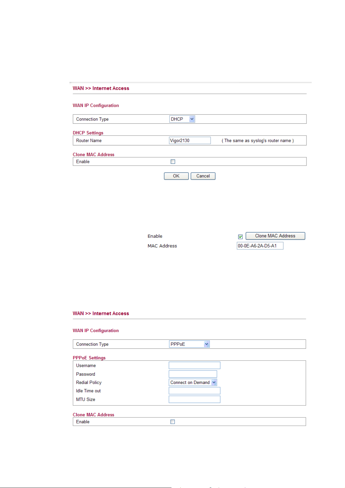
DDHHCCPP
DHCP allows a user to obtain an IP address automatically from a DHCP server on the Internet.
If you choose DHCP mode, the DHCP server of your ISP will assign a dynamic IP address for
your router automatically. It is not necessary for you to assign any setting,
Router Name Type in a name for the router. It must be the same as the name
used in Syslog.
Clone MAC Address It is available when the box of Enable is checked. Click Clone
MAC Address. The result will be displayed in the field of
MAC Address.
After finishing all the settings here, please click OK to activate them.
PPPPPPooEE
To choose PPPoE as the accessing protocol of the internet, please select PPPoE from the
Internet Access menu. The following web page will be shown.
Username Type in the username provided by ISP in this field.
Vigor2130 Series User’s Guide
35
Page 44
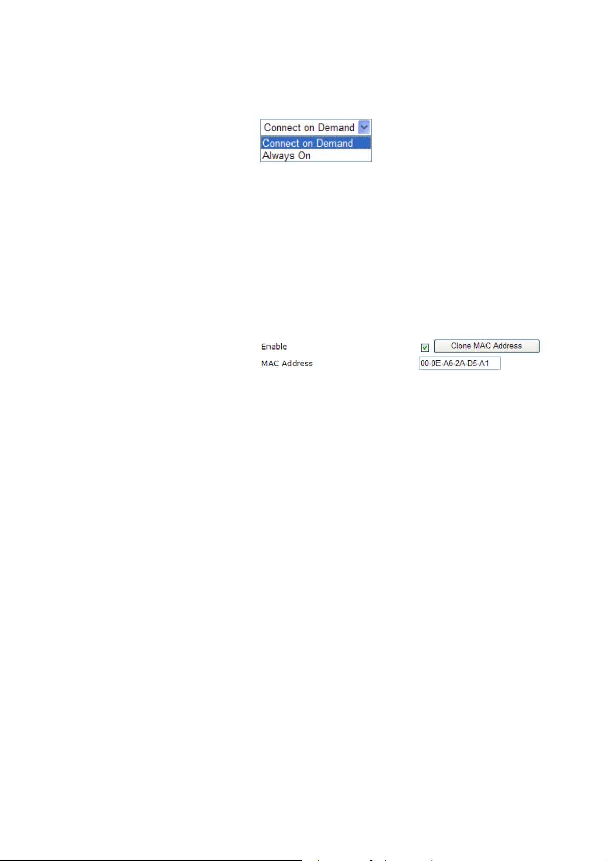
Password Type in the password provided by ISP in this field.
Redial Policy If you want to connect to Internet all the time, you can choose
Always On. Otherwise, choose Connect on Demand.
Idle Time Out Set the timeout for breaking down the Internet after passing
through the time without any action. When you choose Connect
on Demand, you have to type value here.
MTU Size
It means Max Transmit Unit for packet. The default
setting is 1442.
Leave blank for default value.
Enable/Disable Click Enable for activating this function. If you click Disable,
this function will be closed and all the settings that you adjusted
in this page will be invalid.
Clone MAC Address It is available when the box of Enable is checked. Click Clone
MAC Address. The result will be displayed in the field of
MAC Address.
After finishing all the settings here, please click OK to activate them.
36
Vigor2130 Series User’s Guide
Page 45

PPPPTTPP//LL22TTPP
To use PPTP/L2TP as the accessing protocol of the internet, please choose PPTP/L2TP from
Connection Type drop down menu. The following web page will be shown.
Username Type in the username provided by ISP in this field.
Password Type in the password provided by ISP in this field.
Server Address Type in the IP address for PPTP /L2TP server.
WAN IP Network Settings You can choose Static IP or DHCP as WAN IP network setting.
IP Address Type the IP address if you choose Static IP as the WAN IP
network setting.
Subnet Mask Type the subnet mask if you chose Static IP as the WAN IP.
Redial Policy If you want to connect to Internet all the time, you can choose
Always On. Otherwise, choose Connect on Demand and
Idle Time Out Set the timeout for breaking down the Internet after passing
through the time without any action. When you choose Connect
on Demand, you have to type value here.
MTU Size
It means Max Transmit Unit for packet. The default
setting is 1442.
Clone MAC Address It is available when the box of Enable is checked. Click Clone
Vigor2130 Series User’s Guide
MAC Address. The result will be displayed in the field of
MAC Address.
37
Page 46

After finishing all the settings here, please click OK to activate them.
33GG UUSSBB MMooddeemm
If your router connects to a 3G modem and you want to access Internet via 3G modem, choose
3G as connection type and type the required information in this web page.
SIM PIN code Type PIN code of the SIM card that will be used to access
Internet.
Modem Initial String1/2 Such value is used to initialize USB modem. Please use the
default value. If you have any question, please contact to your
ISP.
APN Name
APN means Access Point Name which is provided and
required by some ISPs.
Modem Dial String Such value is used to dial through USB mode. Please use the
default value. If you have any question, please contact to your
ISP.
PPP Username Type the PPP username (optional).
PPP Password Type the PPP password (optional).
Clone MAC Address It is available when the box of Enable is checked. Click Clone
MAC Address. The result will be displayed in the field of
MAC Address.
After finishing all the settings here, please click OK to activate them.
38
Vigor2130 Series User’s Guide
Page 47

33..11..22 PPoorrttss
Ports page is used to change the setting for WAN port. You can set or reset the following
items. All of them are described in detail below.
Port It displays current network interface.
Link It displays current connection status. Green light means the
WAN connection is successful.
Current It displays current speed that the router uses.
Speed Configured It can set the speed and duplex of the port. You can use the drop
down list to choose the required speed for the router. If you
have no idea in configuring speed, simple use the default setting,
Auto.
Flow Control If flow control is enabled by checking Configured box, both
parties can send PAUSE frame to the transmitting device(s) if
the receiving port is too busy to handle. If not, there will be no
flow control in the port. It drops the packet if too much to
handle.
Current Rx: indicates whether pause frames on the port are
obeyed.
Current Tx: indicates whether pause frames on the port are
transmitted.
Maximum Frame This module offers 1518~9600 (Bytes) length to make the long
Excessive Collision Mode There are two modes for you to choose when excessive
Vigor2130 Series User’s Guide
packet for data transmission.
collision happened in half-duplex condition.
39
Page 48

Discard - It determines whether the MAC drops frames after an
excessive collision has occurred. If yes, a frame is dropped after
excessive collision. This is IEEE Standard 802.3 half-duplex
flow control operation.
Restart - It determines whether the MAC retransmits frames
after an excessive collision has occurred. If set, a frame is not
dropped after excessive collisions, but the backoff sequence is
restarted. This is a violation of IEEE Standard 802.3, but is
useful in non-dropping half-duplex flow control operation.
Power Control The Configured column allows for changing the power savings
mode parameters per port.
Refresh Click this button to refresh the information for WAN port.
After finishing all the settings here, please click OK to activate them.
33..11..33 33GG BBaacckkuupp
This page is used to setup 3G backup function. If you enable 3G backup, make sure your
WAN connection type is not in 3G mode. When the WAN connection is broken, router will
try to keep the connection with 3G mode. After WAN connection is recovered, router will
disconnect the 3G connection automatically.
Disabled: All power savings mechanisms disabled.
ActiPHY: Link down power savings enabled.
PerfectReach: Link up power savings enabled.
Enabled: Both link up and link down power savings enabled.
SIM PIN code Type PIN code of the SIM card that will be used to access
Internet.
40
Vigor2130 Series User’s Guide
Page 49
Modem Initial String1/2 Such value is used to initialize USB modem. Please use the
default value. If you have any question, please contact to your
ISP.
33..22 LLAANN
APN Name
Modem Dial String Such value is used to dial through USB mode. Please use the
PPP Username Type the PPP username (optional).
PPP Password Type the PPP password (optional).
Clone MAC Address It is available when the box of Enable is checked. Click Clone
APN means Access Point Name which is provided and
required by some ISPs.
default value. If you have any question, please contact to your
ISP.
MAC Address. The result will be displayed in the field of
MAC Address.
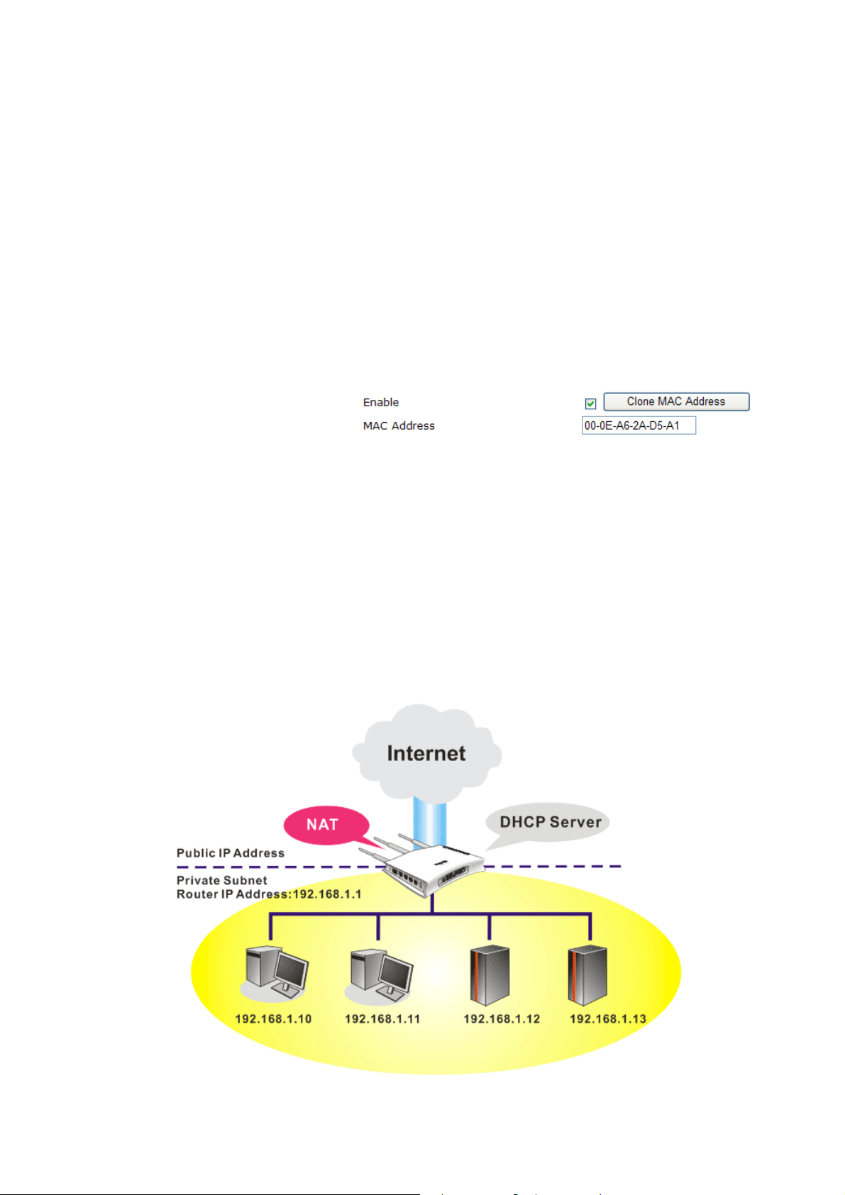
Local Area Network (LAN) is a group of subnets regulated and ruled by router. The design of
network structure is related to what type of public IP addresses coming from your ISP.
BBaassiiccss ooff LLAANN
The most generic function of Vigor router is NAT. It creates a private subnet of your own. As
mentioned previously, the router will talk to other public hosts on the Internet by using public
IP address and talking to local hosts by using its private IP address. What NAT does is to
translate the packets from public IP address to private IP address to forward the right packets
to the right host and vice versa. Besides, Vigor router has a built-in DHCP server that assigns
private IP address to each local host. See the following diagram for a briefly understanding.
Vigor2130 Series User’s Guide
41
Page 50

In some special case, you may have a public IP subnet from your ISP such as
220.135.240.0/24. This means that you can set up a public subnet or call second subnet that
each host is equipped with a public IP address. As a part of the public subnet, the Vigor router
will serve for IP routing to help hosts in the public subnet to communicate with other public
hosts or servers outside. Therefore, the router should be set as the gateway for public hosts.
WWhhaatt iiss RRoouuttiinngg IInnffoorrmmaattiioonn PPrroottooccooll ((RRIIPP))
Vigor router will exchange routing information with neighboring routers using the RIP to
accomplish IP routing. This allows users to change the information of the router such as IP
address and the routers will automatically inform for each other.
WWhhaatt aarree VViirrttuuaall LLAANNss aanndd RRaattee CCoonnttrrooll
You can group local hosts by physical ports and create up to 4 virtual LANs. To manage the
communication between different groups, please set up rules in Virtual LAN (VLAN) function
and the rate of each.
42
Vigor2130 Series User’s Guide
Page 51

Below shows the LAN menu:
33..22..11 GGeenneerraall SSeettuupp
This page provides you the general settings for LAN. Click LAN to open the LAN settings page and choose General Setup.
IP Addr ess Type in private IP address for connecting to a local private
Subnet Mask Type in an address code that determines the size of the network.
network (Default: 192.168.1.1).
(Default: 255.255.255.0/ 24)
Enable DHCP DHCP stands for Dynamic Host Configuration Protocol. The
router by factory default acts a DHCP server for your network
so it automatically dispatch related IP settings to any local user
configured as a DHCP client. It is highly recommended that you
leave the router enabled as a DHCP server if you do not have a
DHCP server for your network.
You can configure the router to serve as a DHCP server for the
2nd subnet. Check the box to enable DHCP server setting.
Start IP Address Enter a value of the IP address pool for the DHCP server to start
with when issuing IP addresses. If the 2nd IP address of y our
router is 220.135.240.1, the starting IP address must be
220.135.240.2 or greater, but smaller than 220.135.240.254.
IP Pool Counts Enter the number of IP addresses in the pool. The maximum is
10. For example, if you type 3 and the 2nd IP address of your
router is 220.135.240.1, the range of IP address by the DHCP
server will be from 220.135.240.2 to 220.135.240.11.
Lease Time It allows you to set the leased time for the specified PC.
After finishing all the settings here, please click OK to activate them.
Vigor2130 Series User’s Guide
43
Page 52

33..22..22 PPoorrttss
Ports page is used to change the setting for LAN ports. You can set or reset the following
items. All of them are described in detail below.
Port It displays current network interface.
Link It displays current connection status. Green light means the
LAN connection is successful.
Current It displays current speed that the router uses.
Speed Configured It can set the speed and duplex of the port. You can use the drop
down list to choose the required speed for the router. If you
have no idea in configuring speed, simple use the default setting,
Auto.
Flow Control If flow control is enabled by checking Configured box, both
parties can send PAUSE frame to the transmitting device(s) if
the receiving port is too busy to handle. If not, there will be no
flow control in the port. It drops the packet if too much to
handle.
Current Rx: indicates whether pause frames on the port are
obeyed.
Current Tx: indicates whether pause frames on the port are
transmitted.
Maximum Frame This module offers 1518~9600 (Bytes) length to make the long
packet for data transmission.
Excessive Collision Mode There are two modes for you to choose when excessive
collision happened in half-duplex condition.
44
Vigor2130 Series User’s Guide
Page 53

Discard - It determines whether the MAC drops frames after an
excessive collision has occurred. If yes, a frame is dropped after
excessive collision. This is IEEE Standard 802.3 half-duplex
flow control operation.
Restart - It determines whether the MAC retransmits frames
after an excessive collision has occurred. If set, a frame is not
dropped after excessive collisions, but the backoff sequence is
restarted. This is a violation of IEEE Standard 802.3, but is
useful in non-dropping half-duplex flow control operation.
Power Control The Configured column allows for changing the power savings
mode parameters per port.
Disabled: All power savings mechanisms disabled.
ActiPHY: Link down power savings enabled.
PerfectReach: Link up power savings enabled.
Enabled: Both link up and link down power savings enabled.
Refresh Click this button to refresh the information for LAN ports.
After finishing all the settings here, please click OK to activate them.
33..22..33 MMAACC AAddddrreessss TTaabbllee
This page allows you to set timeouts for entries in dynamic MAC Table and configure the
static MAC table here.
Vigor2130 Series User’s Guide
45
Page 54
Disable Automatic Aging Stop the MAC table aging timer, the learned MAC address will
not age out automatically. The default setting is enabled. Check
the box to disable this function if required.
Age Time Delete a MAC address idling for a period of time from the
following MAC Table, which will not affect static MAC
address. Range of MAC Address Aging Time is 10-1000000
seconds. The default Aging Time is 300 seconds.
MAC Table Learning List the port members which apply dynamic learning
mechanism or not.
Auto - Enable this port MAC address dynamic learning
mechanism.
Disable - Disable this port MAC address dynamic learning
mechanism, only support static MAC address setting.
Secure - Disable this port MAC address dynamic learning
mechanism and copy the dynamic learning packets to CPU.
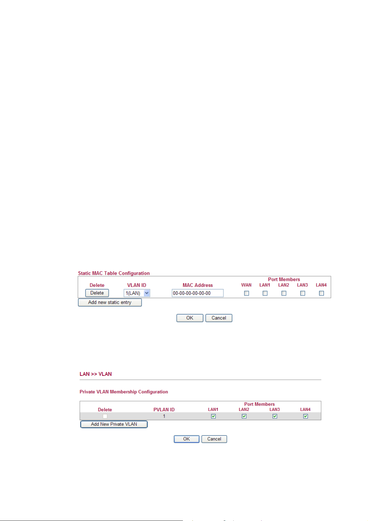
Static MAC Table Config.. Specify static MAC address with VLAN ID to apply aging
configuration.
Delete - Click the button to remove the VLAN setting.
VLAN ID - Specify the interface for the port members.
MAC Address - It is a six-byte long Ethernet hardware address
and usually expressed by hex and separated by hyphens. For
example, 00 – 40 - C7 - D6 – 00 – 02.
WAN/LAN1~4 - Check the port to apply this VLAN setting.
To add a new static MAC entry, click Add new static entry. A new entry will be shown as
follows. Choose VLAN ID and type a new MAC address. Next, specify port member for this
table. Finally, click OK to save the changes.
33..22..44 VVLLAANN
Virtual LAN function provides you a very convenient way to manage hosts by grouping them based on the physical port. You can also manage the in/out rate of each port. Go to LAN page and select VLAN. The following page will appear. VLAN function is enabled in default.
Add New Private VLAN Click this button to add a new private VLAN. The router allows
you to add up to 4 VLAN.
46
Vigor2130 Series User’s Guide
Page 55
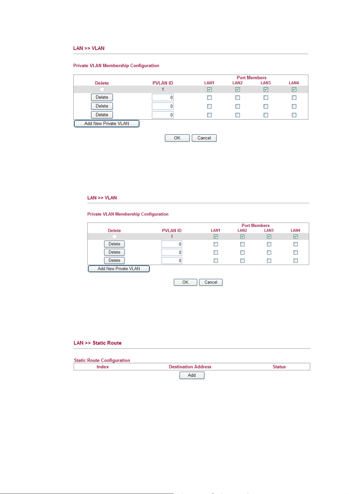
To add or remove a VLAN, please refer to the following example.
1. VLAN 1 is consisted of hosts linked to P1 ~ P4.
2. After checking the box to enable VLAN function, you will check the table according to
the needs as shown below.
3. To remove VLAN, click the Delete button for the one you want to remove and click OK
to save the results.
33..22..55 SSttaattiicc RRoouuttee
Go to LAN to open setting page and choose Static Route.
Index The number (1 to 10) under Index displays current static router.
Destination Address Display the destination address of the static route.
Status Display the status of the static route.
Add Add a new static route.
Vigor2130 Series User’s Guide
47
Page 56

AAdddd SSttaattiicc RRoouutteess ttoo PPrriivvaattee aanndd PPuubblliicc NNeettwwoorrkkss
Here is an example of setting Static Route in Main Router so that user A and B locating in
different subnet can talk to each other via the router. Assuming the Internet access has been
configured and the router works properly:
z use the Main Router to surf the Internet.
z create a private subnet 192.168.10.0 using an internal Router A (192.168.1.2)
z create a public subnet 211.100.88.0 via an internal Router B (192.168.1.3).
z have set Main Router 192.168.1.1 as the default gateway for the Router A 192.168.1.2.
Before setting Static Route, user A cannot talk to user B for Router A can only forward
recognized packets to its default gateway Main Router.
1. Click the LAN - Static Route and click Add. Check the Enable box. Please add a static
route as shown below, which regulates all packets destined to 192.168.10.0 will be
forwarded to 192.168.1.2. Click OK.
2. Return to Stati c Route page. Click Add again to add another static route as show below,
which regulates all packets destined to 211.100.88.0 will be forwarded to 192.168.1.3.
48
Vigor2130 Series User’s Guide
Page 57
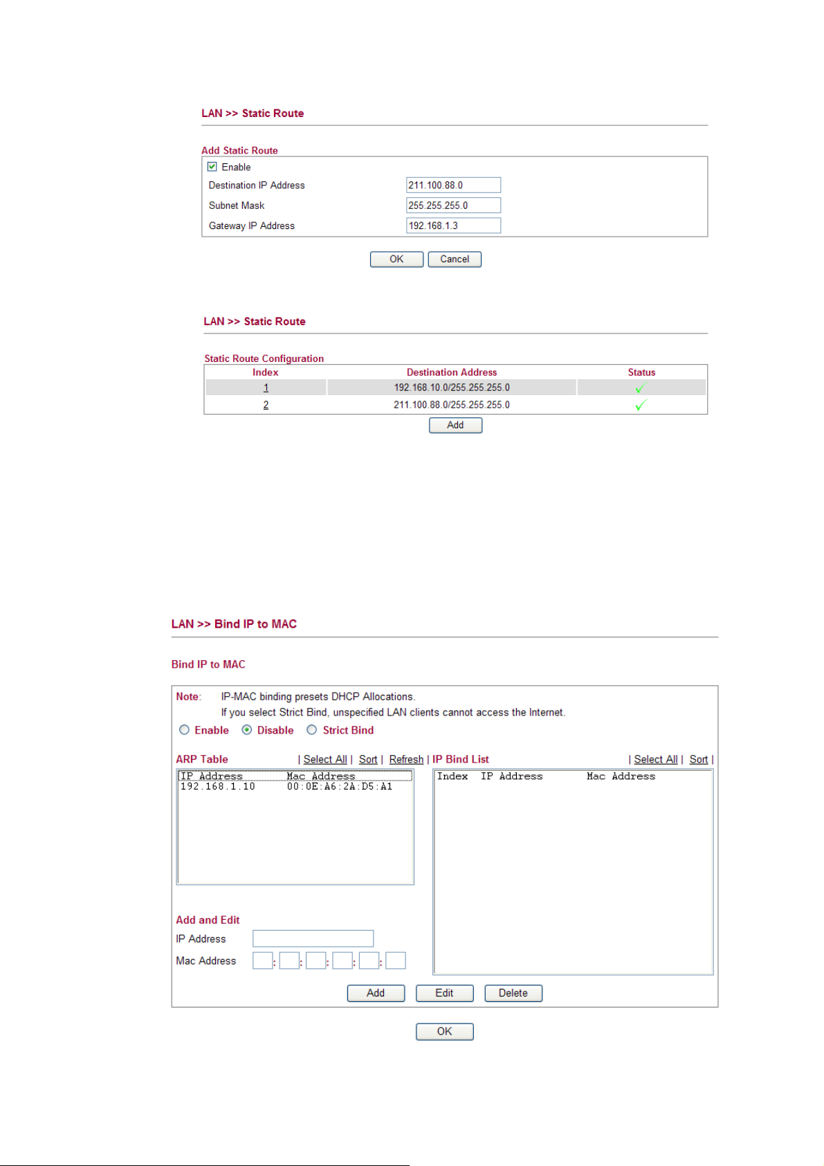
3. Verify current routing table.
33..22..66 BBiinndd IIPP ttoo MMAACC
This function is used to bind the IP and MAC address in LAN to have a strengthening control
in network. When this function is enabled, all the assigned IP and MAC address binding
together cannot be changed. If you modified the binding IP or MAC address, it might cause
you not access into the Internet.
Click LAN and click Bind IP to MAC to open the setup page.
Vigor2130 Series User’s Guide
49
Page 58

Enable Click this radio button to invoke this function. However,
IP/MAC which is not listed in IP Bind List also can connect to
Internet.
Disable Click this radio button to disable this function. All the settings
on this page will be invalid.
Strict Bind Click this radio button to block the connection of the IP/MAC
which is not listed in IP Bind List.
ARP Table This table is the LAN ARP table of this router. The information
for IP and MAC will be displayed in this field. Each pair of IP
and MAC address listed in ARP table can be selected and added
to IP Bind List by clicking Add below
.
Add and Edit IP Address – Type the IP address that will be used for the
specified MAC address.
Mac Address – Type the MAC address that is used to bind
with the assigned IP address.
Refresh It is used to refresh the ARP table. When there is one new PC
added to the LAN, you can click this link to obtain the newly
ARP table information.
33..33 NNAATT
IP Bind List It displays a list for the IP bind to MAC information.
Add It allows you to add the one you choose from the ARP table or
the IP/MAC address typed in Add and Edit to the table of IP
Bind List.
Edit It allows you to edit and modify the selected IP address and
MAC address that you create before.
Remove You can remove any item listed in IP Bind List. Simply click
and select the one, and click Remove. The selected item will be
removed from the IP Bind List.
Note: Before you select Strict Bind, you have to bind one set of IP/MAC address for one
PC. If not, no one of the PCs can access into Internet. And the web configurator of the router
might not be accessed.
Usually, the router serves as an NAT (Network Address Translation) router. NAT is a
mechanism that one or more private IP addresses can be mapped into a single public one.
Public IP address is usually assigned by your ISP, for which you may get charged. Private IP
addresses are recognized only among internal hosts.
When the outgoing packets destined to some public server on the Internet reach the NAT
router, the router will change its source address into the public IP address of the router, select
the available public port, and then forward it. At the same time, the router shall list an entry in
a table to memorize this address/port-mapping relationship. When the public server response,
the incoming traffic, of course, is destined to the router’s public IP address and the router will
do the inversion based on its table. Therefore, the internal host can communicate with external
host smoothly.
The benefit of the NAT includes:
z Save cost on applying public IP address and apply efficient usage of IP address.
NAT allows the internal IP addresses of local hosts to be translated into one public IP
address, thus you can have only one IP address on behalf of the entire internal hosts.
50
Vigor2130 Series User’s Guide
Page 59

z Enhance security of the internal network by obscuring the IP address. There are
many attacks aiming victims based on the IP address. Since the attacker cannot be aware
of any private IP addresses, the NAT function can protect the internal network.
On NAT page, you will see the private IP address defined in RFC-1918. Usually we use the
192.168.1.0/24 subnet for the router. As stated before, the NAT facility can map one or
more IP addresses and/or service ports into different specified services. In other words, the
NAT function can be achieved by using port mapping methods.
Below shows the menu items for NAT.
33..33..11 HHaarrddwwaarree NNAATT
Hardware-base Acceleration Engine, also named Protocol Processing Engine API is the
function that Draytek provides to extremely speed up the NAT performance.
While the hardware acceleration mechanism is activated, most of the bandwidth usage will
be concentrated on the specific sessions which increase transmission speed to get ultimately
accelerated.
With Hardware NAT, LAN to WAN NAT throughput can be over 900M bps. But be sure that
your PC has Giga Ethernet and connect with CAT6 Ethernet cable.
33..33..22 OOppeenn PPoorrttss
Open Ports allows you to open a range of ports for the traffic of special applications.
Common application of Open Ports includes P2P application (e.g., BT, KaZaA, Gnutella,
WinMX, eMule and others), Internet Camera etc. Ensure that you keep the application
involved up-to-date to avoid falling victim to any security exploits.
To add a new open port, click Add new entry.
Vigor2130 Series User’s Guide
51
Page 60
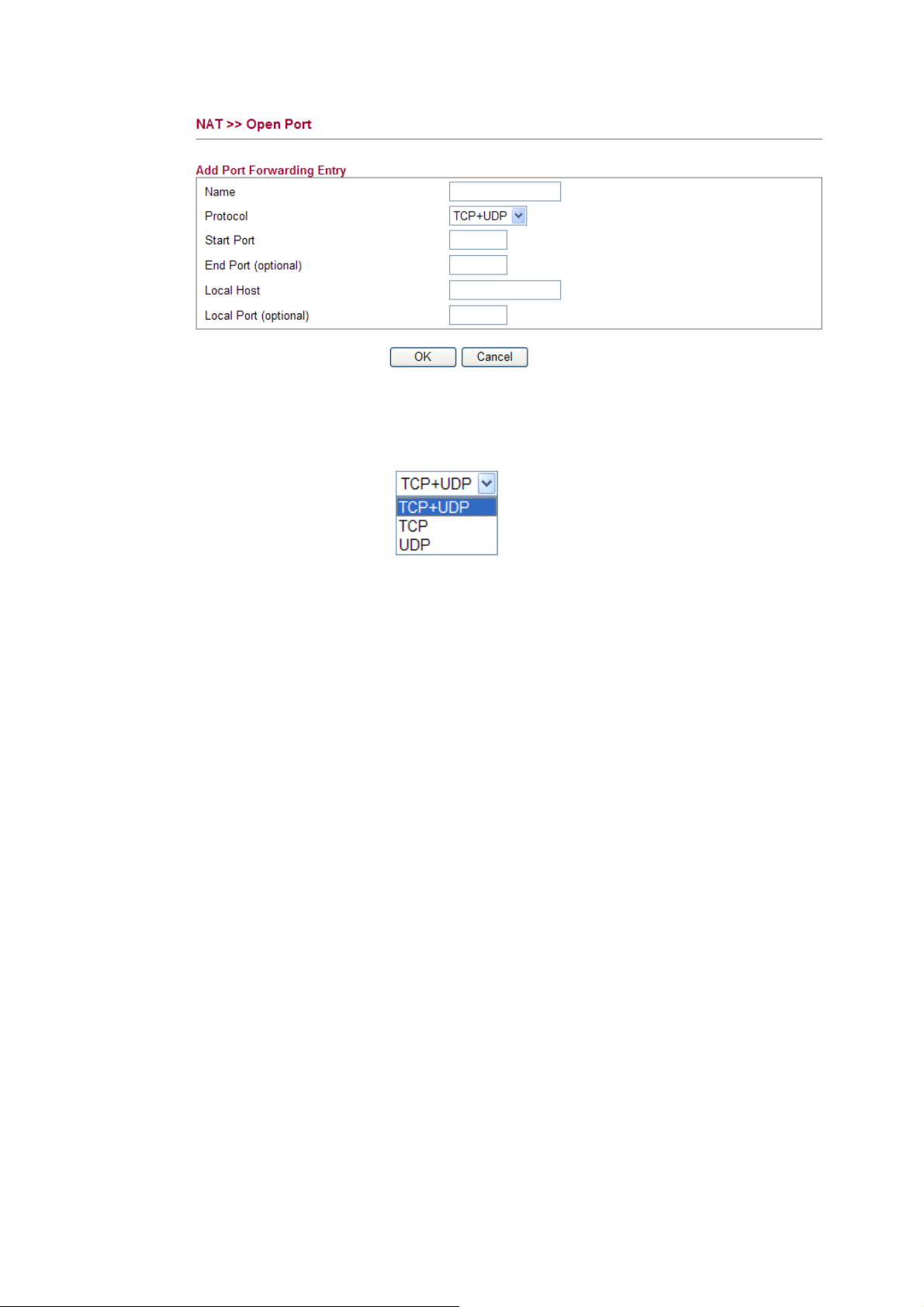
Name Specify the name for the defined network service.
Protocol Specify the transport layer protocol. It could be TCP, UDP and
TCP+UDP.
Start Port Specify the starting port number of the service offered by the
local host.
End Port (optional) Specify the ending port number of the service offered by the
local host.
Local Host Enter the private IP address of the local host.
Local Port (optional) If it is configured, the forwarded traffic is mapped to this port
on the local host.
52
Vigor2130 Series User’s Guide
Page 61

33..33..33 DDMMZZ HHoosstt
Vigor router provides a facility DMZ Host that maps ALL unsolicited data on any protocol to
a single host in the LAN. Regular web surfing and other such Internet activities from other
clients will continue to work without inappropriate interruption. DMZ Host allows a defined
internal user to be totally exposed to the Internet, which usually helps some special
applications such as Netmeeting or Internet Games etc.
Note: The security properties of NAT are somewhat bypassed if you set up DMZ host. We
suggest you to add additional filter rules or a secondary firewall.
Click DMZ Host to open the following page:
Enable Check to enable the DMZ Host function.
DMZ IP Enter the private IP address of the DMZ host, or click Choose
PC to select one.
Vigor2130 Series User’s Guide
53
Page 62
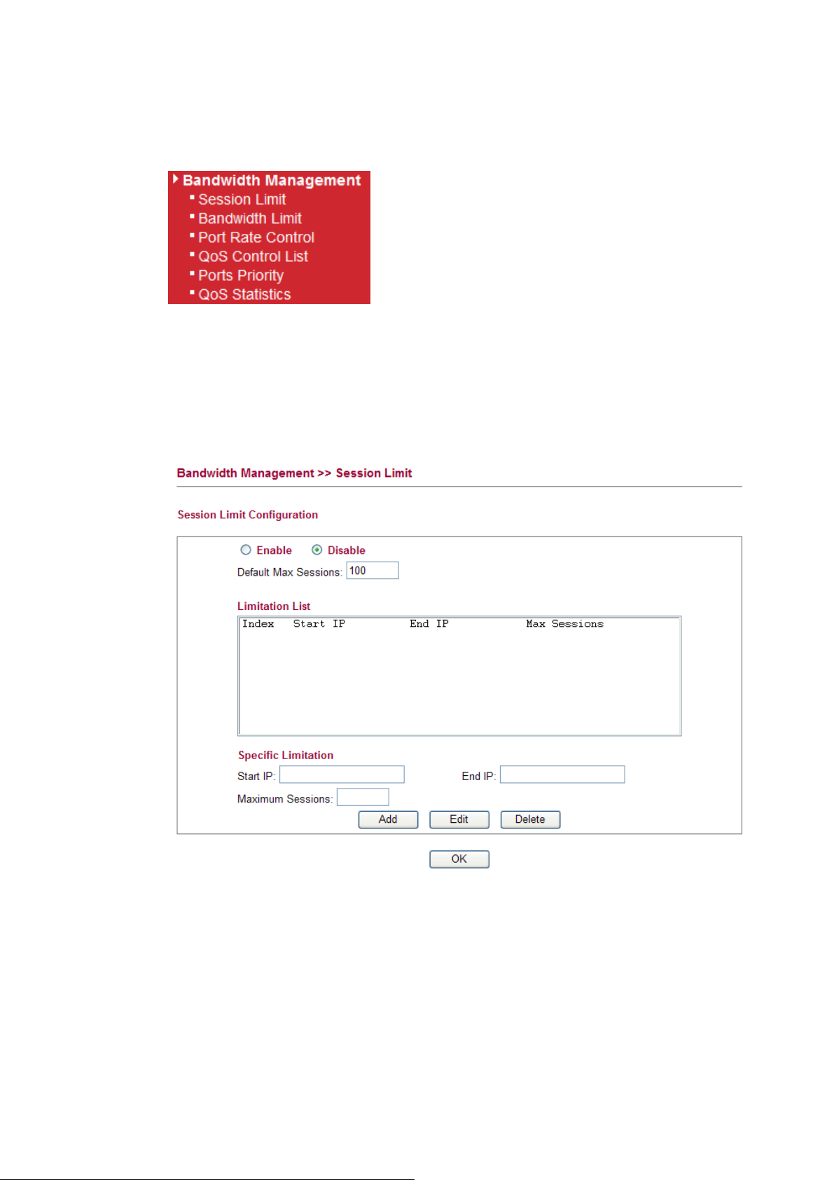
33..44 BBaannddwwiiddtthh MMaannaaggeemmeenntt
Below shows the menu items for Bandwidth Management.
33..44..11 SSeessssiioonn LLiimmiitt
A PC with private IP address can access to the Internet via NAT router. The router will
generate the records of NAT sessions for such connection. The P2P (Peer to Peer) applications
(e.g., BitTorrent) always need many sessions for procession and also they will occupy over
resources which might result in important accesses impacted. To solve the problem, you can
use limit session to limit the session procession for specified Hosts.
In the Bandwidth Management menu, click Sessions Limit to open the web page.
To activate the function of limit session, simply click Enable and set the default session limit.
Enable Click this button to activate the function of limit session.
Disable Click this button to close the function of limit session.
Default Max Sessions Defines the default session number used for each computer in
LAN.
Limitation List Displays a list of specific limitations that you set on this web
page.
Start IP Defines the start LAN IP address for limit session.
54
Vigor2130 Series User’s Guide
Page 63

End IP Defines the end LAN IP address for limit session.
Maximum Sessions Defines the av ailable session number for each host in the
specific range of IP addresses. If you do not set the session
number in this field, the system will use the default session limit
for the specific limitation you set for each index.
Add Adds the specific session limitation onto the list above.
Edit Allows you to edit the settings for the selected limitation.
Delete Remove the selected settings existing on the limitation list.
When you finish adding a new session limit, simply click OK. The following page will appear
for you to check.
33..44..22 BBaannddwwiiddtthh LLiimmiitt
The downstream or upstream from FTP, HTTP or some P2P applications will occupy large of
bandwidth and affect the applications for other programs. Please use Limit Bandwidth to make
the bandwidth usage more efficient.
In the Bandwidth Management menu, click Bandwidth Limit to open the web page.
To activate the function of limit bandwidth, simply click Enable and set the default upstream
and downstream limit.
Enable Click this button to activate the function of limit bandwidth.
Disable Click this button to close the function of limit bandwidth.
Default TX limit Define the default speed of the upstream for each computer in
Vigor2130 Series User’s Guide
LAN.
55
Page 64
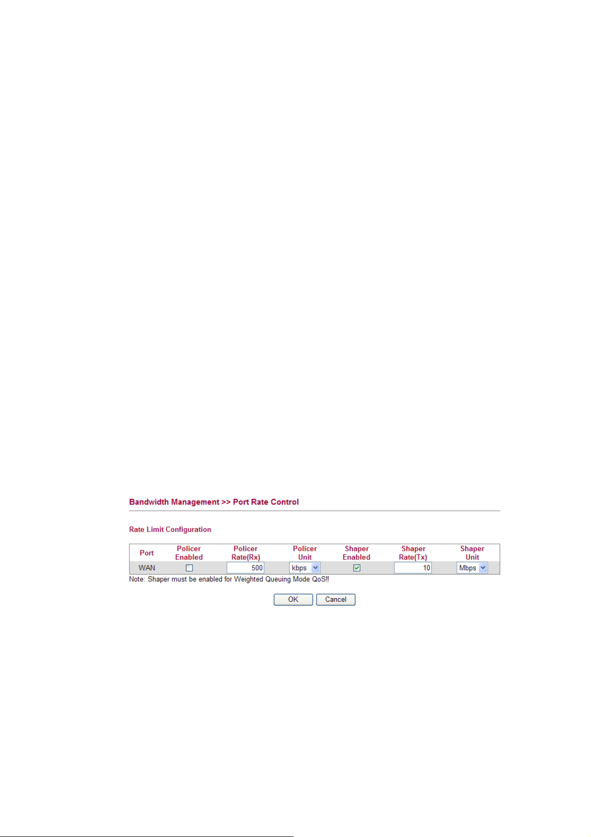
Default RX limit Define the default speed of the downstream for each computer
in LAN.
Limitation List Display a list of specific limitations that you set on this web
page.
Start IP Bandwidth limit can be applied on certain IP range. That’s, only
the PCs within the range will be influenced by the bandwidth
limitation set here. Please define the start IP address for the
specific limitation.
End IP Define the end IP address for the specific limitation.
TX Limit Define the limitation for the speed of the upstream to be applied
as specific limitation. If you do not set the limit in this field, the
system will use the default speed for the specific limitation you
set for each index.
RX Limit Define the limitation for the speed of the downstream to be
applied as specific limitation. If you do not set the limit in this
field, the system will use the default speed for the specific
limitation you set for each index.
Add Add the specific speed limitation onto the list above.
Edit Allows you to edit the settings for the selected limitation.
Delete Remove the selected settings existing on the limitation list.
When you finish adding a new bandwidth limit, simply click OK. The following page will
appear for you to check.
33..44..33 PPoorrtt RRaattee CCoonnttrrooll
A policer can limit the bandwidth of received frames. It is located in front of the ingress queue.
And a shaper can limit the bandwidth of transmitted frames. It is located after the ingress
queues. This page allows you to configure the switch port rate limit for Policers and Shapers.
Port Represent LAN or WAN interface.
Policer Enabled Check this box to enable policer function.
Policer Rate(Rx) Type the number for policer function. The default value is 500.
It is restricted to 500-1000000 when the Policer Unit is set in
kbps, and it is restricted to 1-1000 when the Policer Unit is set
in Mbps.
Policer Unit Determine the unit (kbps/Mbps) for policer.
Shaper Enabled Check this box to enable shaper function.
56
Vigor2130 Series User’s Guide
Page 65

Shaper Rate (Tx) Type the number for shaper function. The default value is 500.
It is restricted to 500-1000000 when the Shaper Unit is set in
kbps, and it is restricted to 1-1000 when the Shaper Unit is set
in Mbps.
Shaper Unit Determine the unit (kbps/Mbps) for shaper function.
33..44..44 QQooSS CCoonnttrrooll LLiisstt
Deploying QoS (Quality of Service) management to guarantee that all applications receive the
service levels required and sufficient bandwidth to meet performance expectations is indeed
one important aspect of modern enterprise network.
One reason for QoS is that numerous TCP-based applications tend to continually increase their
transmission rate and consume all available bandwidth, which is called TCP slow start. If
other applications are not protected by QoS, it will detract much from their performance in the
overcrowded network. This is especially essential to those are low tolerant of loss, delay or
jitter (delay variation).
Another reason is due to congestions at network intersections where speeds of interconnected
circuits mismatch or traffic aggregates, packets will queue up and traffic can be throttled back
to a lower speed. If there’s no defined priority to specify which packets should be discarded
(or in another term “dropped”) from an overflowing queue, packets of sensitive applications
mentioned above might be the ones to drop off. How this will affect application performance?
There are two components within Primary configuration of QoS deployment:
z Classification: Identifying low-latency or crucial applications and marking them for
high-priority service level enforcement throughout the network.
z Scheduling: Based on classification of service level to assign packets to queues and
associated service types
The basic QoS implementation in Vigor routers is to classify and schedule packets based on
the service type information in the IP header. For instance, to ensure the connection with the
headquarter, a teleworker may enforce an index of QoS Control to reserve bandwidth for
HTTPS connection while using lots of application at the same time.
One more larger-scale implementation of QoS network is to apply DSCP (Differentiated
Service Code Point) and IP Precedence disciplines at Layer 3. Compared with legacy IP
Precedence that uses Type of Service (ToS) field in the IP header to define 8 service classes,
DSCP is a successor creating 64 classes possible with backward IP Precedence compatibility.
In a QoS-enabled network, or Differentiated Service (DiffServ or DS) framework, a DS
domain owner should sign a Service License Agreement (SLA) with other DS domain owners
to define the service level provided toward traffic from different domains. Then each DS node
in these domains will perform the priority treatment. This is called per-hop-behavior (PHB).
The definition of PHB includes Expedited Forwarding (EF), Assured Forwarding (AF), and
Best Effort (BE). AF defines the four classes of delivery (or forwarding) classes and three
levels of drop precedence in each class.
Vigor routers as edge routers of DS domain shall check the marked DSCP value in the IP
header of bypassing traffic, thus to allocate certain amount of resource execute appropriate
policing, classification or scheduling. The core routers in the backbone will do the same
checking before executing treatments in order to ensure service-level consistency throughout
the whole QoS-enabled network.
Vigor2130 Series User’s Guide
57
Page 66

However, each node may take different attitude toward packets with high priority marking
since it may bind with the business deal of SLA among different DS domain owners. It’s not
easy to achieve deterministic and consistent high-priority QoS traffic throughout the whole
network with merely Vigor router’s effort.
In the Bandwidth Management menu, click QoS Control List (QCL) to open the web page.
QCE Type Display the type of that QCE (QoS Control Entries).
Type Value Display the value specified for the QCE.
Traffic Class Display the class of the data transmission for the QCE.
QoS Control List allows users to set up to five groups of QCL. Each QCL group can contain
12 QCE settings.
58
Vigor2130 Series User’s Guide
Page 67

AAddddiinngg aa NNeeww QQCCEE
Click to add a new QCE onto this page. Different QCE type will bring out different web
settings.
z If you choose Ethernet Type as QCE Type, you have to type value for it and specify
traffic class from Low, Normal, Medium and High.
Ethernet Type Value Either 8~63 ASCII characters, such as 012345678(or 64
Hexadecimal digits leading by 0x, such as "0x321253abcde...").
z If you choose VLAN ID as QCE Type, you have to type the ID number for it and specify
traffic class from Low, Normal, Medium and High.
z If you choose TCP/UDP Port as QCE Type, you have to type the port number for it and
specify traffic class from Low, Normal, Medium and High.
Vigor2130 Series User’s Guide
59
Page 68

TCP/UDP Port Click Single or Range. If you select Range, you have to type
in the starting port number and the end porting number on
the boxes below.
TCP/UDP Port Range Type in the starting port number and the end porting number
here if you choose Range as the type.
z If you choose DSCP as QCE Type, you have to type value for it and specify traffic class
from Low, Normal, Medium and High.
z If you choose ToS as QCE Type, you have to specify priority class from Low, Normal,
Medium and High.
z If you choose Tag Priority as QCE Type, you have to specify priority class from Low,
Normal, Medium and High.
60
Vigor2130 Series User’s Guide
Page 69

EEddiittiinngg aa QQCCEE
Click to modify the settings of an existing QCE on this page.
MMoovviinngg UUpp//DDoowwnn aa QQCCEE
Click and to move a QCE up and down.
DDeelleettiinngg aa QQCCEE
To delete a QCE in the list, simply click of that one. It will be removed immediately.
33..44..55 PPoorrttss PPrriioorriittyy
This page allows you to configure QoS settings for each port. The classification is controlled
by a QCL (Quality Control List) that is assigned to each port. A QCL consists of an ordered
list of up to 12 QCEs (Quality Control Entry). Each QCE can be used to classify certain
frames to a specific QoS class. This classification can be based on parameters such as VLAN
ID, UDP/TCP port, IPv4/IPv6 DSCP or Tag Priority. Frames not matching any of the QCEs
are classified to the default QoS class for the port.
Port Indicate the interface for the physical port, WAN port, LAN
Vigor2130 Series User’s Guide
port and Wireless Port.
61
Page 70

Default Class Use the drop down list to choose the priority for each port.
QCL Use the drop down list to choose the QCL number defined in
QoS Control List for the port.
Queuing Mode Use the drop down list to choose suitable mode.
Queue Weighted Use the drop down list to choose 1, 2, 4, or 8 as the queue
33..44..66 QQooSS SSttaattiissttiiccss
This page displays statistics for QoS setting. Click WAN/LAN link to check detailed
information for each interface.
weighted number.
Click WAN/LAN link to check detailed information for each interface.
62
Vigor2130 Series User’s Guide
Page 71

Rx Packets Display the counting number of the packet received.
Rx Octets Display the total received bytes.
Rx Unicast Display the counting number of the received unicast packet.
Rx Broadcast Display the counting number of the received broadcast packet.
Rx Pause Display the counting number of the received pause packet.
RX 64 Bytes Display the number of 64-byte frames in good and bad packets
received.
RX 65-127 Bytes Display the number of 65 ~ 127-byte frames in good and bad
packets received.
RX 128-255 Bytes Display the number of 128 ~ 255-byte frames in good and bad
packets received.
RX 256-511 Bytes Display the number of 256 ~ 511-byte frames in good and bad
packets received.
RX 512-1023 Bytes Display the number of 512 ~ 1023-byte frames in good and bad
packets received.
RX 1024- 1526 Bytes Display the number of 1024-1522-byte frames in good and bad
packets received.
RX 1527 Bytes Display the number of 1527-byte frames in good and bad
Vigor2130 Series User’s Guide
packets received.
63
Page 72

Rx Low Display the low queue counter of the packet received.
Rx Normal Display the normal queue counter of the packet received.
Rx Medium Display the medium queue counter of the packet received.
Rx High Display the high queue counter of the packet received.
Rx Drops Display the number of frames dropped due to the lack of
receiving buffer.
Rx CRC/Alignment Display the number of Alignment errors packets received.
Rx Undersize Display the number of short frames (<64 Bytes) with valid
CRC.
Rx Oversize Display the number of long frames (according to max_length
register) with valid CRC.
Rx Fragments Display the number of short frames (< 64 bytes) with invalid
CRC.
Rx Jabber Display the number of long frames (according tomax_length
register) with invalid CRC.
Rx Filtered Display the filtered number of the packet received.
Tx Packets Display the counting number of the packet transmitted.
Tx Octets Display the total transmitted bytes.
Tx Unicast Display the show the counting number of the transmitted
unicast packet.
Tx Multicast Display the show the counting number of the transmitted
multicast packet.
Tx Broadcast Display the counting number of the transmitted broadcast
packet.
Tx Pause Show the counting number of the transmitted pause packet.
Tx 64 Bytes Display the number of 64-byte frames in good and bad packets
transmitted.
Tx 65-127 Bytes Display the number of 65 ~ 127-byte frames in good and bad
packets transmitted.
Tx 128-255 Bytes Display the number of 128 ~ 255-byte frames in good and bad
packets transmitted.
Tx 256-511 Bytes Display the number of 256 ~ 511-byte frames in good and bad
packets transmitted.
Tx 512-1023 Bytes Display the number of 512 ~ 1023-byte frames in good and bad
packets transmitted.
Tx 1024- 1526 Bytes Display the number of 1024 ~ 1522-byt frames in good and bad
packets transmitted.
Tx 1527 Bytes: Display the number of 1527-byte frames in good and bad
packets transmitted.
Tx Low Display the low queue counter of the packet transmitted.
Tx Normal Display the normal queue counter of the packet transmitted.
Tx Medium Display the medium queue counter of the packet received.
64
Vigor2130 Series User’s Guide
Page 73

Tx High Display the high queue counter of the packet received.
Tx Drops Display the number of frames dropped due to excessive
collision, late collision, or frame aging.
Tx lat/Exc.Coll. Display the number of Frames late collision or excessive
collision Error, which switch transmitted
33..55 AApppplliiccaattiioonnss
Below shows the menu items for Applications.
33..55..11 DDyynnaammiicc DDNNSS
The ISP often provides you with a dynamic IP address when you connect to the Internet via
your ISP. It means that the public IP address assigned to your router changes each time you
access the Internet. The Dynamic DNS feature lets you assign a domain name to a dynamic
WAN IP address. It allows the router to update its online WAN IP address mappings on the
specified Dynamic DNS server. Once the router is online, you will be able to use the
registered domain name to access the router or internal virtual servers from the Internet. It is
particularly helpful if you host a web server, FTP server, or other server behind the router.
Before you use the Dynamic DNS feature, you have to apply for free DDNS service to the
DDNS service providers. The router provides up to three accounts from three different DDNS
service providers. Basically, Vigor routers are compatible with the DDNS services supplied by
most popular DDNS service providers such as www.dyndns.org, www.no-ip.com,
www.dtdns.com, www.changeip.com, www.dynamic- nameserver.com. You should visit
their websites to register your own domain name for the router.
Enable Dynamic DNS Check this box to enable the current account.
DynDNS Service Select the service provider for the DDNS account.
Hostname Type in one domain name that you applied previously. Use the
Username Type in the login name that you set for applying domain.
Vigor2130 Series User’s Guide
drop down list to choose the desired domain.
65
Page 74

Password Type in the password that you set for applying domain.
Check IP change every Set the interval for checking the information.
Force IP update every Force the router updates its information to DDNS server with
Click OK button to activate the settings. You will see your setting has been saved.
33..55..22 SScchheedduullee
The Vigor router has a built-in real time clock which can update itself manually or
automatically by means of Network Time Protocols (NTP). As a result, you can not only
schedule the router to dialup to the Internet at a specified time, but also restrict Internet access
to certain hours so that users can connect to the Internet only during certain hours, say,
business hours. The schedule is also applicable to other functions.
You have to set your time before set schedule. In System Maintenance>> Time and Date
menu, press Inquire Time button to set the Vigor router’s clock to current time of your PC.
The clock will reset once if you power down or reset the router. There is another way to set up
time. You can inquiry an NTP server (a time server) on the Internet to synchronize the router’s
clock. This method can only be applied when the WAN connection has been built up.
the interval set here.
You can set up to 15 schedules. To add a schedule profile, please click Add.
Enable Check to enable the schedule.
Start Date Specify the starting date of the schedule.
Start Time Specify the starting time of the schedule.
Action Specify which action Call Schedule should apply during the
period of the schedule.
Force On -Force the connection to be always on.
Force Down -Force the connection to be always down.
Enable Dial-On-Demand -Specify the connection to be
dial-on-demand and the value of idle timeout should be
66
Vigor2130 Series User’s Guide
Page 75
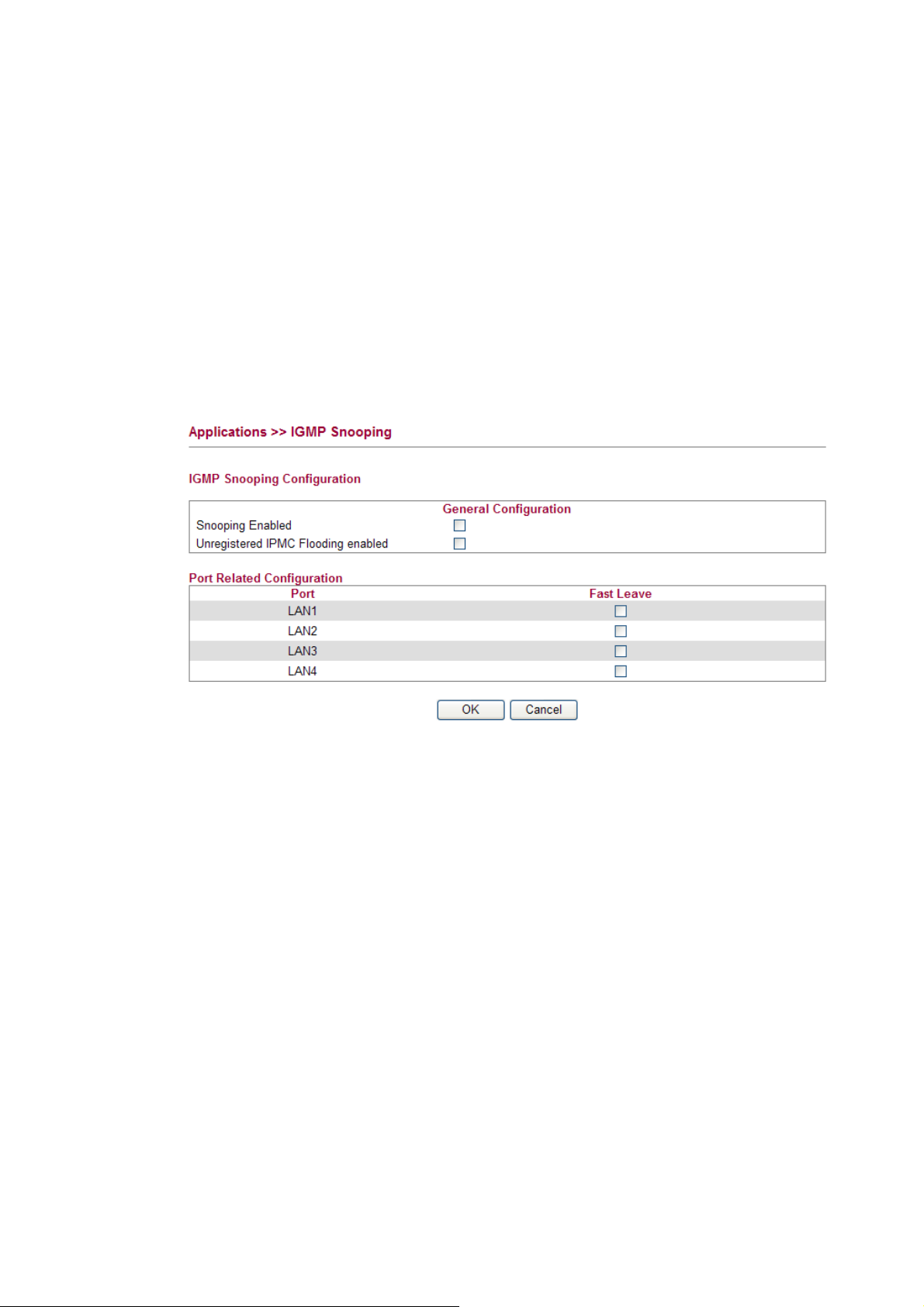
specified in Idle Timeout field.
Disable Dial-On-Demand -Specify the connection to be up
when it has traffic on the line. Once there is no traffic over idle
timeout, the connection will be down and never up again during
the schedule.
Acts Specify how often the schedule will be applied
Once -The schedule will be applied just once
Routine or Weekdays -Specify which days in one week should
perform the schedule.
33..55..33 IIGGMMPP SSnnooooppiinngg
IGMP snooping means multicast traffic will be forwarded to ports that have members of that
group. If you disable IGMP snooping, the system will make multicast traffic treated in the
same manner as broadcast traffic.
Snooping Enabled Check the box to enable this function.
Unregistered IPMC… Check the box to enable unregistered IPMC traffic flooding
Fast Leave Check the box to Fast Leave on the LAN port.
Vigor2130 Series User’s Guide
67
Page 76

33..55..44 IIGGMMPP SSttaattuuss
This page display current IGMP snooping status.
V1~3 Reports Receive Display the number of Received V1 – V3 Reports.
V2 Leave Receive Display the number of Received V2 Leave.
Groups Display current
IGMP groups. Maximum number of group
for each VLAN can be set is 128.
Port Members Display the LAN ports in this group.
Refresh Click this button to refresh the page immediately.
Clear Click this button to clear the settings on this page.
33..55..55 UUPPnnPP CCoonnffiigguurraattiioonn
The UPnP (Universal Plug and Play) protocol is supported to bring to network connected
devices the ease of installation and configuration which is already available for directly
connected PC peripherals with the existing Windows 'Plug and Play' system. For NAT routers,
the major feature of UPnP on the router is “NAT Traversal”. This enables applications inside
the firewall to automatically open the ports that they need to pass through a router. It is more
reliable than requiring a router to work out by itself which ports need to be opened. Further,
the user does not have to manually set up port mappings or a DMZ. UPnP is available on
Windows XP and the router provide the associated support for MSN Messenger to allow full
use of the voice, video and messaging features.
Enable UPNP Enable UPnP function. You have to type the download and
upload speed.
68
Vigor2130 Series User’s Guide
Page 77

After setting Enable UPNP Service setting, an icon of IP Broadband Connection on Router
on Windows XP/Network Connections will appear. The connection status and control status
will be able to be activated. The NAT Traversal of UPnP enables the multimedia features of
your applications to operate. This has to manually set up port mappings or use other similar
methods. The screenshots below show examples of this facility.
The UPnP facility on the router enables UPnP aware applications such as MSN Messenger to
discover what are behind a NAT router. The application will also learn the external IP address
and configure port mappings on the router. Subsequently, such a facility forwards packets from
the external ports of the router to the internal ports used by the application.
The reminder as regards concern about Firewall and UPnP
Can't work with Firewall Software
Enabling firewall applications on your PC may cause the UPnP function not working
properly. This is because these applications will block the accessing ability of some network
ports.
Security Considerations
Activating the UPnP function on your network may incur some security threats. You should
consider carefully these risks before activating the UPnP function.
Vigor2130 Series User’s Guide
69
Page 78

¾ Some Microsoft operating systems have found out the UPnP weaknesses and hence
you need to ensure that you have applied the latest service packs and patches.
¾ Non-privileged users can control some router functions, including removing and
adding port mappings.
The UPnP function dynamically adds port mappings on behalf of some UPnP-aware
applications. When the applications terminate abnormally, these mappings may not be
removed.
33..66 WWiirreelleessss LLAANN
This function is used for “n” models.
33..66..11 BBaassiicc CCoonncceeppttss
Over recent years, the market for wireless communications has enjoyed tremendous growth.
Wireless technology now reaches or is capable of reaching virtually every location on the
surface of the earth. Hundreds of millions of people exchange information every day via
wireless communication products. The Vigor “n” model, a.k.a. Vigor wireless router, is
designed for maximum flexibility and efficiency of a small office/home. Any authorized staff
can bring a built-in WLAN client PDA or notebook into a meeting room for conference
without laying a clot of LAN cable or drilling holes everywhere. Wireless LAN enables high
mobility so WLAN users can simultaneously access all LAN facilities just like on a wired
LAN as well as Internet access
The Vigor wireless routers are equipped with a wireless LAN interface compliant with the
standard IEEE 802.11n draft 2 protocol. To boost its performance further, the Vigor Router is
also loaded with advanced wireless technology to lift up data rate up to 300 Mbps*. Hence,
you can finally smoothly enjoy stream music and video.
Note:
* The actual data throughput will vary according to the network conditions and
environmental factors, including volume of network traffic, network overhead and
building materials.
In an Infrastructure Mode of wireless network, Vigor wireless router plays a role as an Access
Point (AP) connecting to lots of wireless clients or Stations (STA). All the STAs will share the
same Internet connection via Vigor wireless router. The General Settings will set up the
information of this wireless network, including its SSID as identification, located channel etc.
70
Vigor2130 Series User’s Guide
Page 79

SSeeccuurriittyy OOvveerrvviieeww
Real-time Hardware Encryption: Vigor Router is equipped with a hardware AES encryption
engine so it can apply the highest protection to your data without influencing user experience.
Complete Security Standard Selection: To ensure the security and privacy of your wireless
communication, we provide several prevailing standards on market.
WEP (Wired Equivalent Privacy) is a legacy method to encrypt each frame transmitted via
radio using either a 64-bit or 128-bit key. Usually access point will preset a set of four keys
and it will communicate with each station using only one out of the four keys.
WPA (Wi-Fi Protected Access), the most dominating security mechanism in industry, is
separated into two categories: WPA-personal or called WPA Pre-Share Key (WPA/PSK), and
WPA-Enterprise or called WPA/802.1x.
In WPA-Personal, a pre-defined key is used for encryption during data transmission. WPA
applies Temporal Key Integrity Protocol (TKIP) for data encryption while WPA2 applies AES.
The WPA-Enterprise combines not only encryption but also authentication.
Since WEP has been proved vulnerable, you may consider using WPA for the most secure
connection. You should select the appropriate security mechanism according to your needs.
No matter which security suite you select, they all will enhance the over-the-air data
protection and /or privacy on your wireless network. The Vigor wireless router is very flexible
and can support multiple secure connections with both WEP and WPA at the same time.
Below shows the menu items for Wireless LAN.
33..66..22 GGeenneerraall SSeettuupp
By clicking the General Setup, a new web page will appear so that you could configure the SSID and the wireless channel.
Please refer to the following figure for more information.
Enable Wireless LAN Check the box to enable the wireless function.
Vigor2130 Series User’s Guide
71
Page 80

SSID Broadcast Choose Show to make the SSID being seen by wireless clients.
Choose Hide to prevent from wireless sniffing and make it
harder for unauthorized clients or STAs to join your wireless
LAN.
SSID It means the identification of the wireless LAN. SSID can be
any text numbers or various special characters. The default
SSID is "DrayTek". We suggest you to change it.
Wireless Mode Choose the wireless mode for this router. At present, only
802.11B/B/N mix is available.
Country Region Code It represents different country region code.
Use the drop down list to choose the one that fit the usage of
regulations locally.
Channel It means the channel of frequency of the wireless LAN. The
default channel is 11. You may switch channel if the selected
channel is under serious interference. If you have no idea of
choosing the frequency, please select Auto to let system
determine for you.
Encryption Select an appropriate encryption mode to improve the security
and privacy of your wireless data packets.
Each encryption mode will bring out different web page and ask
you to offer additional configuration.
WWiirreelleessss SSeeccuurriittyy CCoonnffiigguurraattiioonn
For the security of your system, choose the proper encryption for data transmission. Different
encryption mode will bring out different setting encryption ways.
z None
The encryption mechanism is turned off.
z WEP
Accepts only WEP clients and the encryption key should be entered in WEP Key.
72
Vigor2130 Series User’s Guide
Page 81

Default Key All wireless devices must support the same WEP
encryption bit size and have the same key.
Key1-Key4 Four keys can be entered here, but only one key can be
selected at a time. The format of WEP Key is restricted to
5 ASCII characters or 10 hexadecimal values in 64-bit
encryption level, or restricted to 13 ASCII characters or 26
hexadecimal values in 128-bit encryption level. The
allowed content is the ASCII characters from 33(!) to
126(~) except '#' and ',' .
Authentication Mode Choose OPEN or SHARED as the authentication mode.
OPEN: Set wireless to authentication open mode.
SHARED: Set wireless to authentication shared mode.
z WPA-PSK
Accepts only WPA clients and the encryption key should be entered in PSK. The WPA
encrypts each frame transmitted from the radio using the key, which either PSK
(Pre-Shared Key) entered manually in this field below or automatically negotiated via
802.1x authentication.
WPA Mode Select WPA, WPA2 or Auto as the type.
Vigor2130 Series User’s Guide
73
Page 82

WP A Algorithm Select TKIP, AES or auto as the algorithm for WPA.
WPA Pre-Shared Key Either 8~63 ASCII characters, such as 012345678..(or 64
Hexadecimal digits leading by 0x, such as
"0x321253abcde...").
z WPA-RADIUS
The built-in RADIUS client feature enables the router to assist the remote dial-in user or
a wireless station and the RADIUS server in performing mutual authentication. It enables
centralized remote access authentication for network management.
Type The WPA encrypts each frame transmitted from the radio
using the key, which either PSK (Pre-Shared Key) entered
manually in this field below or automatically negotiated
via 802.1x authentication. Select WPA, WPA2 or Auto as
WPA mode.
WPA Algorithm Choose the WPA algorithm, TKIP, AES or Auto.
Server IP Address Enter the IP address of RADIUS server.
Destination Port The UDP port number that the RADIUS server is using.
The default value is 1812, based on RFC 2138.
Shared Secret The RADIUS server and client share a secret that is used
to authenticate the messages sent between them. Both
sides must be configured to use the same shared secret.
z WPS
WPS (Wi-Fi Protected Setup) provides easy procedure to make network connection
between wireless station and wireless access point (vigor router) with the encryption
of WPA and WPA2.
74
Vigor2130 Series User’s Guide
Page 83

Configure via Push Button Click Start PBC to invoke Push-Button style WPS setup
procedure. The router will wait for WPS requests from
wireless clients about two minutes. The WPS LED on the
router will blink fast when WPS is in progress. It will
return to normal condition after two minutes. (You need to
setup WPS within two minutes)
Configure via Client PinCode Type the PIN code specified in wireless client you
wish to connect, and click Start PIN button. The WLAN
LED on the router will blink fast when WPS is in progress.
It will return to normal condition after two minutes. (You
need to setup WPS within two minutes
It is the simplest way to build connection between wireless network clients and vigor
router. Users do not need to select any encryption mode and type any long encryption
passphrase to setup a wireless client every time. He/she only needs to press a button on
wireless client, and WPS will connect for client and router automatically.
Note: Such function is available for the wireless station with WPS supported.
There are two methods to do network connection through WPS between AP and Stations:
pressing the Start PBC button or using PIN Code.
On the side of Vigor 2130 series which served as an AP, press WPS button once on the
front panel of the router or click Start PBC on web configuration interface. On the side
Vigor2130 Series User’s Guide
75
Page 84

of a station with network card installed, press Start PBC button of network card.
If you want to use PIN code, you have to know the PIN code specified in wireless client.
Then provide the PIN code of the wireless client you wish to connect to the vigor router.
33..66..33 AAcccceessss CCoonnttrrooll
For additional security of wireless access, the Access Control facility allows you to restrict the network access right by controlling the wireless LAN MAC address of client. Only the valid MAC address that has been configured can access the wireless LAN interface. By clicking the Access Control, a new web page will appear, as depicted below, so that you could edit the clients' MAC addresses to control their access rights (deny or allow).
Filter Type Choose the rule for the MAC addresses displayed in this
page.
Allow List – all the MAC address of wireless clients listed
here are allowed to do wireless connection.
76
Vigor2130 Series User’s Guide
Page 85

Deny List – all the MAC address of wireless clients listed
here will be blocked.
Add a New Entry Add a new MAC address into the list.
Delete Delete the selected MAC address in the list. This button
will appear only an entry of MAC Address has been typed.
Cancel Give up the configuration.
OK Click it to save the configuration.
33..66..44 SSttaattiioonn LLiisstt
Station List provides the knowledge of connecting wireless clients now along with its status code.
Index Display the number of the connecting client.
IP Address Display the WAN IP address for the connecting client.
MAC Address Display the MAC Address for the connecting client.
Connected Time Display the connection time for the connecting client.
Auto-refresh Check this box to force the system refresh ing the table
Refresh Click this button to refresh current page.
automatically.
Vigor2130 Series User’s Guide
77
Page 86

33..66..55 AAcccceessss PPooiinntt DDiissccoovveerryy
Vigor router can scan all regulatory channels and find working APs in the neighborhood.
Based on the scanning result, users will know which channel is clean for usage.
Note: During the scanning process (about 5 seconds), no client is allowed to connect to
Vigor.
The table will list channel, SSID, BSSID, Encryption type, Authorization type and the Signal
strength of working APs in the neighborhood.
Channel Display the channel for the scanned AP.
SSID Display the SSID of the scanned AP.
BSSID Display the MAC address of the scanned AP.
Enc Display the encryption type of the scanned AP.
Auth Display the authentication method of the scanned AP.
Signal Display the strength (in percentage) of the signal of the
Scan It is used to discover all the connected AP. The results will
33..77 UUSSBB AApppplliiccaattiioonn
USB diskette can be regarded as an FTP server. By way of Vigor router, uses on LAN/WAN
can access, write and read data stored in USB diskette. After setting the configuration in USB
Application, you can type the IP address of the Vigor router and username/password created
in USB Application>>FTP User Management on the FTP client software. Thus, the client
can use the FTP site (USB diskette) through Vigor router.
scanned AP.
be shown on the box above this button.
33..77..11 UUSSBB GGeenneerraall SSeettttiinnggss
At present, the Vigor router can support USB diskette with versions of FAT16 and FAT32
only. Therefore, before connecting the USB diskette into the Vigor router, please make sure
78
Vigor2130 Series User’s Guide
Page 87

the memory format for the USB diskette is FAT16 or FAT32. It is recommended for you to
use FAT32 for viewing the filename completely (FAT16 cannot support long filename).
Enable FTP Check this box to enable FTP connection.
Enable Disk Sharing Check this box to enable Samba file sharing.
Workgroup Name Type the name for FTP users for accessing into FTP server
(USB diskette). Be aware that users cannot access into USB
diskette in anonymity. Later, you can open FTP client software
and type the username specified here for accessing into USB
storage diskette.
33..77..22 FFTTPP UUsseerr MMaannaaggeemmeenntt
This page allows you to change user setting for USB storage disk. Before modifying settings
in this page, please insert a USB diskette and configure settings in User>>User
Configuration first. Otherwise, an error message will appear to warn you.
Click the name link under User Name to open the setting web page.
User Name It displays the username that user uses to login to the FTP
Volume Select the proper volume for the connected USB diskette.
Home Folder It determines the range for the client to access into.
Vigor2130 Series User’s Guide
server.
The user can enter a directory name in this field. Then,
after clicking OK, the router will create the specific/new
folder in the USB diskette. In addition, if the user types “/”
79
Page 88

here, he/she can access into all of the disk folders and files
in USB diskette.
Note: When write protect status for the USB diskette is
ON, you cannot type any new folder name in this field.
Only “/” can be used in such case.
Access Rule Select the access right for the USB diskette.
When you finish the settings, simply click OK to save the configuration.
33..77..33 DDiisskk SSttaattuuss
This page can display current using status of the USB diskette. If you want to remove the
diskette from USB port in router, please check the box of Safely Remove Disk first. And then,
click Update and remove the USB diskette later.
Safely Remove Disk Check this box and then you can remove the USB diskette
Manufacturer Display the manufacturer of the disk.
Model Display the model of the disk.
Size Display the storage space of the diskette(s).
Status Display current usage status of the diskette(s)
Update Click this button to refresh the disk status.
safely.
33..77..44 DDiisskk SShhaarreess
This page can define the folder which will be shared while Samba File Sharing is enabled.
To add a new entry for disk sharing, please click Add a New Entry to open the following
page.
80
Vigor2130 Series User’s Guide
Page 89

Share Name Type a name to be used as shared folder name in Samba service.
The name must not contain spaces or special characters.
Comment Type the brief description for the disk sharing. The words here
will be seen in Network Neighborhood on Windows client
computers
Volume Select the proper volume for the connected USB diskette.
Path It determines the range for the client to access into.
The user can enter a directory name in this field. Then,
after clicking OK, the router will create the specific/new
folder in the USB diskette. In addition, if the user types “/”
here, he/she can access into all of the disk folders and files
in USB diskette.
Note: When write protect status for the USB diskette is
ON, you cannot type any new folder name in this field.
Only “/” can be used in such case.
Visible Check this box to make the shared folder to be seen in Network
Neighborhood on Windows of clients in local network.
Access Rights Specify the access right and apply to all the wireless clients that
want to connect to the attached USB diskette.
Vigor2130 Series User’s Guide
All Users Read-only - everyone has read-only access to the
share disk.
All Users Read-write - everyone has read-write access to the
share disk.
Specific Users – Only specific user(s) can access into the share
disk.
81
Page 90

33..88 UUsseerr
33..88..11 UUsseerr CCoonnffiigguurraattiioonn
This page allows you to set user’s setting that allowed to use PPTP, FTP, IPSEC/L2TP
connection.
AAddddiinngg aa NNeeww UUsseerr
Click Add a New User to open the following page.
Username Type a name for this user.
Full Name Type full name for this user.
Password Type the password for this user.
Password (again) Type the password again for confirmation.
Allow Disk Sharing Check this box to enable Samba file sharing.
Allow IPSEC/L2TP Check this box to let the user connect via IPSEC/L2TP.
Allow PPTP Check this box to let the user connect via PPTP.
Allow FTP Check this box to let the user connect to FTP server.
When you finish the settings, simply click OK to save the configuration. The new user will be
created and displayed on the page.
82
Vigor2130 Series User’s Guide
Page 91

EEddiittiinngg//DDeelleettiinngg UUsseerr SSeettttiinnggss
To edit a user, click the name link under Username to open the following page. Modify the
settings except Username and then click OK to save and exit it. If you want to remove such
user settings, simply click Delete User.
33..99 SSyysstteemm MMaaiinntteennaannccee
For the system setup, there are several items that you have to know the way of configuration:
Status, User Password, Configuration Backup, Syslog/Mail Alert, Time and Date,
Management, Reboot System and Firmware Upgrade.
Below shows the menu items for System Maintenance.
33..99..11 SSyysstteemm SSttaattuuss
The System Status provides basic network settings of Vigor router. It includes LAN and WAN interface information. Also, you could get the current running firmware version or firmware related information from this presentation.
Vigor2130 Series User’s Guide
83
Page 92

Model Name Display the model name of the router.
Platform Display the hardware type that this device is built upon.
Bootloader Version Display the bootloader version of the router.
Firmware Version Display the firmware version of the router.
Build Date/Time Display the date and time of the current firmware build.
Hardware NAT Version Display the hardware acceleration NAT version.
System Date Display current time and date for the system server.
System Uptime Display the connection time for the system server.
LAN-------
MAC Address Display the MAC address of the LAN Interface.
IP Address Display the IP address of the LAN interface.
IP Mask Display the subnet mask address of the LAN interface.
WAN-------
MAC Address Display the MAC address of the WAN Interface.
IP Address Display the IP address of the WAN interface.
IP Mask Display the subnet mask address of the WAN interface.
Default Gateway Display the gateway address of the WAN interface.
Primary DNS Display the specified primary DNS setting.
Secondary DNS Display the specified secondary DNS setting.
Wireless LAN-------
84
Vigor2130 Series User’s Guide
Page 93

MAC Address Display the MAC address of the wireless LAN.
Device Type Display the device type used for wireless LAN.
SSID Display the SSID of the router.
Channel Display the channel that wireless LAN used.
Manufacturer Display the manufacturer of the disk.
Model Display the model of the disk.
Size Display the storage size of the USB diskette.
Status Display current status of the USB diskette.
33..99..22 UUsseerr PPaasssswwoorrdd
This page allows you to set new password for user operation.
Old Password Type in the old password. The factory default setting for
New Password Type in new password in this filed.
Confirm Password Type in the new password again.
When you click OK, the login window will appear. Please use the new password to access into
the web configurator again.
33..99..33 CCoonnffiigguurraattiioonn BBaacckkuupp
password is blank.
BBaacckkuupp tthhee CCoonnffiigguurraattiioonn
Follow the steps below to backup your configuration.
1. Go to System Maintenance >> Configuration Backup. The following windows will be
popped-up, as shown below.
Vigor2130 Series User’s Guide
85
Page 94

2. Click Backup button to get into the following dialog. Click Save button to open another
dialog for saving configuration as a file.
3. In Save As dialog, the default filename is config.cfg. You could give it another name by
yourself.
4. Click Save button, the configuration will download automatically to your computer as a
file named config.cfg.
The above example is using Windows platform for demonstrating examples. The Mac or
Linux platform will appear different windows, but the backup function is still available.
Note: Backup for Certification must be done independently . The Configuration Backup
does not include information of Certificate.
RReessttoorree CCoonnffiigguurraattiioonn
1. Go to System Maintenance >> Configuration Backup. The following windows will be
popped-up, as shown below.
86
Vigor2130 Series User’s Guide
Page 95

2. Click Browse button to choose the correct configuration file for uploading to the router.
Click Restore button and wait for few seconds, the following picture will tell you that
3.
the restoration procedure is successful.
33..99..44 SSyysslloogg // MMaaiill AAlleerrtt
SysLog function is provided for users to monitor router. There is no bother to directly get into
the Web Configurator of the router or borrow debug equipments.
Enable (Syslog Access…) Check the box to activate function of syslog.
Router Name Type a name of this device.
Server IP Address The IP address of the Syslog server.
Destination Port Type a port for the Syslog protocol.
Vigor2130 Series User’s Guide
87
Page 96

Log Level Choose the severity level for the system log entry.
Enable (Mail Alert…) Check the box to activate function of mail alert.
Send a test e-mail Make a si mple test for the e-mail address specified in this
page. Please assign the mail address first and click this
button to execute a test for verify the mail address is
available or not.
SMTP Server The IP address of the SMTP server.
Mail To Assign a mail address for sending mails out.
Mail From Assign a path for receiving the mail from outside.
User Name Type the user name for authentication.
Password Type the password for authentication.
Enable E-mail Alert Check the box of User Login to send alert message to the
e-mail box while the router detecting the item(s) you
specify here.
Click OK to save these settings.
For viewing the Syslog, please do the following:
1. Just set your monitor PC’s IP address in the field of Server IP Address
2. Install the Router Tools in the Utility within provided CD. After installation, click on the
Router Tools>>Syslog from program menu.
3. From the Syslog screen, select the router you want to monitor. Be reminded that in
Network Information, select the network adapter used to connect to the router.
Otherwise, you won’t succeed in retrieving information from the router.
88
Vigor2130 Series User’s Guide
Page 97

33..99..55 TTiimmee aanndd DDaattee
It allows you to specify where the time of the router should be inquired from.
Time Zone Select the time zone where the router is located.
Add NTP server Click the button to add a new NTP server.
Delete Click this button to remove an NTP server.
Click OK to save these settings.
Vigor2130 Series User’s Guide
89
Page 98

33..99..66 MMaannaaggeemmeenntt
This page allows you to manage the settings for access control, access list, port setup, and
SMP setup. For example, as to management access control, the port number is used to
send/receive SIP message for building a session. The default value is 5060 and this must
match with the peer Registrar when making VoIP calls.
Enable HTTP/HTTPS/SSH/ICMP Ping/FTP/SNMP Enable the checkbox to allow system
Access List You could specify that the system administrator can only
33..99..77 RReebboooott SSyysstteemm
The Web Configurator may be used to restart your router for using current configuration. Click Reboot System from System Maintenance to open the following page.
administrators to login from the Internet. There are several
servers provided by the system to allow you managing the
router from Internet. Check the box(es) to specify.
Manager Host IP – Type the IP address for the host to
perform the remote management.
login from a specific host or network defined in the list. A
maximum of three IPs/subnet masks is allowed.
List IP - Indicate an IP address allowed to login to the
router.
Subnet Mask - Represent a subnet mask allowed to login to
the router.
90
Vigor2130 Series User’s Guide
Page 99

Click OK. The router will take 5 seconds to reboot the system.
Note: When the system pops up Reboot System web page after you configure web settings,
please click OK to reboot your router for ensuring normal operation and preventing
unexpected errors of the router in the future.
33..99..88 FFiirrmmwwaarree UUppggrraaddee
Before upgrading your router firmware, you need to install the Router Tools. The Firmware
Upgrade Utility is included in the tools. The following web page will guide you to upgrade
firmware by using an example. Note that this example is running over Windows OS
(Operating System).
Download the newest firmware from DrayTek's web site or FTP site. The DrayTek web site is
www.draytek.com (or local DrayTek's web site) and FTP site is ftp.draytek.com.
Click Maintenance>> Firmware Upgrade to launch the Firmware Upgrade Utility.
For the detailed information about firmware update, please go to Chapter 5.
Vigor2130 Series User’s Guide
91
Page 100

92
Vigor2130 Series User’s Guide
 Loading...