

Page 1
Fitting Instructions
APE (Anchor Point Extended)
Cross Bar Kits for Track & Direct
Mounting Systems
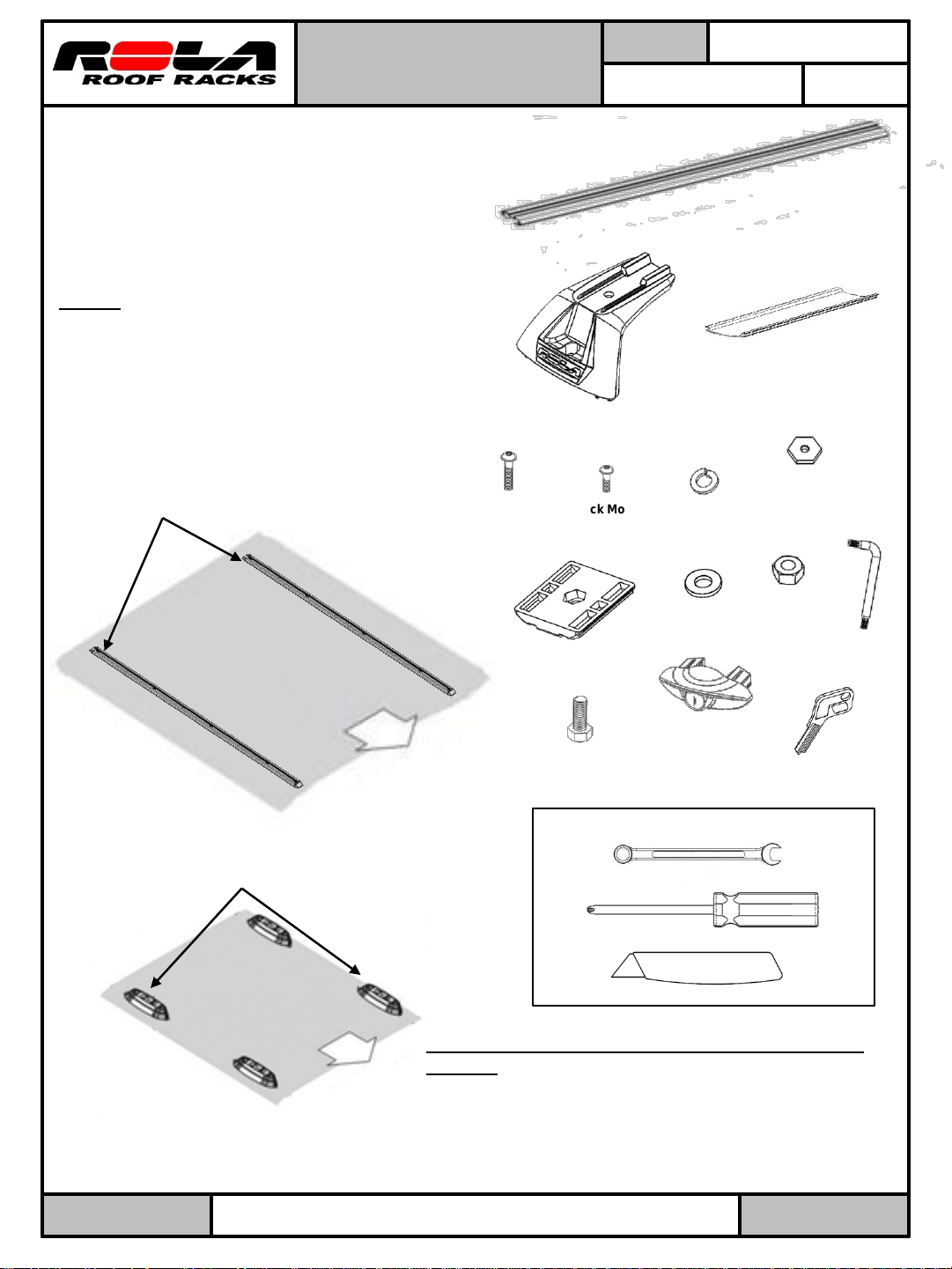
Note: Prior to Assembly
Prior to assembling your cross bar kit check
that the kit contains all the parts you will need
to fit the cross bars. Refer to parts lists for
guidance.
Please read these instructions before assembly.
Step 1: Determine if you have a Direct or
Track mounting roof rack system. These
systems must be installed prior to installing
the cross bar kits. If it’s a Track Mounting
System (part numbers 59853, 59854, &
59855) follow steps 2 and 3. (Fig. 1) If it’s a
Direct Mounting System (part numbers
59753 & 59754) follow steps 4 and 5 (Fig. 2)
Track Systems part numbers
59853 – 59854 - 59855
Direct Mount
Bolt M6 x 24mm
Qty 4
PART No:
CARRYING CAPACITY:
Parts list
Cross Bars
End Support
Qty 4
Track Mount
Bolt M6 x 16mm
Qty 4
M8 Spring
59772, 59773,
59774
75Kgs/
165 Lbs
Qty 2
Under Cover
Qty 2
M6 Hex Nut
Brass
Qty 4
Washer
Qty 4
Vehicle’s roof
Fig. 1
Direct Systems part numbers
59753 – 59754
Vehicle’s roof
Fig. 2
Front of
vehicle
M8 Hex Nut
Qty 4
End Cap Key
Qty 4
Front of
vehicle
M8 Washer
Qty 4
Clamp Plate
Qty 4
Cross Bar End Caps
Qty 4
Bolt
M8 x 20mm
Qty 4
Tools required
13mm or adjustable wrench
Phillips screw driver
Scissors or Blade
Step 2: Installing Cross Bars on a Track Mounting
System.
A. Locate hardware bag labeled “Track Mount
Hardware”.
B. Assemble bolt M6x16 into End Support and thread
on M6 Hex nut brass onto bolt, (Fig. 3)
L Wrench
Qty 1
59772-3-4N REV 4-24-13
Printed in China
Pg 1 of 3
Page 2
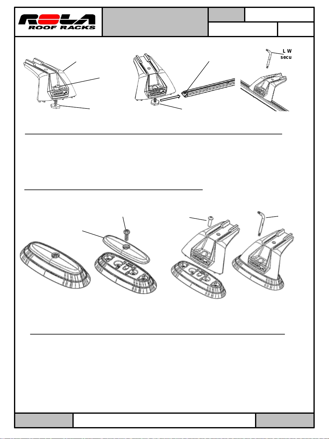
End Support
M6x16 Bolt
Fitting Instructions
APE (Anchor Point Extended)
Cross Bar Kits for Track & Direct
Mounting Systems
Open end of Track
PART No:
59772, 59773,
59774
CARRYING CAPACITY:
75Kgs/
165 Lbs
L Wrench-
security key
M6 Hex Nut
Brass
Fig. 3
To slide into position
do not thread nut past
end of bolt.
Fig. 4
Fig. 5
Step 3: Installing Cross Bars to the vehicle with Track Mounting System. (Continued)
A. Place an End Support and the M6 Hex Nut Brass into the open end of the Track (Fig 4.)
Ensure that the Brass Nut is engaged in the channel. Position it along the rail with the
logo facing out. Turn the bolt approx 2-3 turns with the L Wrench security key (Fig 5).
Do not tighten yet, Repeat for the other 3 End Supports.
B. Go to step 6 to continue installing cross bar.
Step 4: Installing Cross Bars on a Direct Mounting System.
A. Locate hardware bag labeled “Direct Mount Hardware”.
M6- Bolt
Cover
Philips head
M6x24 Bolt
L wrench-
security key
Fig. 6
Fig. 7
Fig. 8
Fig. 9
Step 5: Installing Cross Bars to the vehicle with Direct Mounting System. (Fig. 6)
A. Using a Philips head screw driver remove the top screw and cover from mounting
block. Covers will not be replaced while the cross bars are on the vehicle. Store
the Covers and Bolts for later replacement when cross bars are removed. (Fig. 7)
B. Place End Support on mounting block with the logo facing out. Install the M6x24
bolt through End Support and turn the bolt approx 2-3 turns with the L wrench
security key. (Fig. 8-9) Do not tighten yet, repeat for other 3 End Supports.
C. Go to step 6 to continue installing cross bar.
59772-3-4N REV 4-24-13
Printed in China
Pg 2 of 3
Page 3

Fitting Instructions
APE (Anchor Point Extended)
Cross Bar Kits for Track & Direct
Mounting Systems
Step 6: Fitting Cross Bars to the vehicle
A. Place the Cross Bar onto the End Supports
ensuring that the End Support Tabs are located
into the cutouts on the underside of the bar.
Ensure the Cross Bar marked “FRONT” is
placed on the front End Supports. Check that
the Cross Bar has equally distanced overhang
on either side of the End Supports. (Fig. 10)
B. Insert the M8 hex nut into the Clamp Plate.
Insert the Clamp Plate into the end of the Cross
Bar and align it so that the nut and the End
Support’s bolt hole align.
C. Secure the Cross Bar to the End Support by
screwing the M8 x 20mm bolt with Washer and
Spring Washer through the End Support hole
and into the Clamp Plate nut. (Fig. 11)
D. Using a 13mm or adjustable wrench fully
tighten the bolt on the underside of the
support. Now using the Security Key finish
tightening the M6x16 bolts to 5Nm (44 in/ lbs)
or to a firm hand tightness.
Step 7: Installing Under Cover strips
Mark on underside of bars with a pencil the length
of Under Cover strips needed.
Remove bars, measure length of under cover filler
strips to fill slot. Cut Under Cover pieces using
scissors or a blade. Slide inner most Under Cover
into position on the bars and re-assemble bars
onto vehicle. Add the outer Under Cover piece
once bars are attached. (Fig. 12)
End Cap
PART No:
CARRYING CAPACITY:
Cross Bar
Cross Bar shortened for
illustrative purposes
Tabs
Clamp Plate
Inner Under
Cover strip
Fig. 10
M8 Nut
Fig. 11
Caution sharp
edges
59772, 59773,
59774
75Kgs/
165 Lbs
M8 Washer
Spring Washer
M8 Bolt
Step 8: Install End Caps
Locking End Caps can now be installed into the ends
Slide to end
Fig. 12
Outer Under
Cover strip
of the cross bars. (Fig. 13) Remove keys and keep in
a safe place.
End Cap
To load accessories into the Cross Bar accessory
channel remove End Cap, cut Buffer Strips as needed.
Once accessories have been loaded, re-insert the End
Caps and lock. Additional Buffer Strips may be
purchased from ROLA if needed.
REGULARLY CHECK THE TIGHTNESS OF CROSS BAR & ATTACHMENTS.
Loads should be evenly distributed and secured.
Check the function of all doors and sunroof before driving.
Any weight carried on the vehicle will adversely affect its handling particularly in cornering or in a cross wind and the vehicle
should therefore be driven with increased caution.
For lost key replacement or other service items call customer service: 1-800-632-3290 or visit: www.rolaproducts.com.
Please have lock core number or part numbers available.
Only use NON-STRETCH tie down straps.
A number of accessories for carrying special loads are available.
59772-3-4N REV 4-24-13
Printed in China
Ensure bars are parallel and straps are tightened against
the side rails. Perform a check by tugging on the cross bars.
Fig. 13
Pg 3 of 3
 Loading...