

Page 1
INSTALLATION INSTRUCTIONS
58432 ADAPTER BRACKET RAIL MOUNTING KIT
For updated instructions see
www.reeseprod.com or www.draw-tite.com
DEALER/INSTALLER:
(1) Provide this Manual to end user.
(2) Physically demonstrate procedures in this Manual to end user.
(3) Have end user demonstrate that he/she understands procedures. (1) Read and follow this Manual every time you use Hitch.
FRONT OF TRUCK
END USER:
(2) Save this Manual for future reference.
(3) Pass on copies of Manual to any other user or
owner of Hitch.
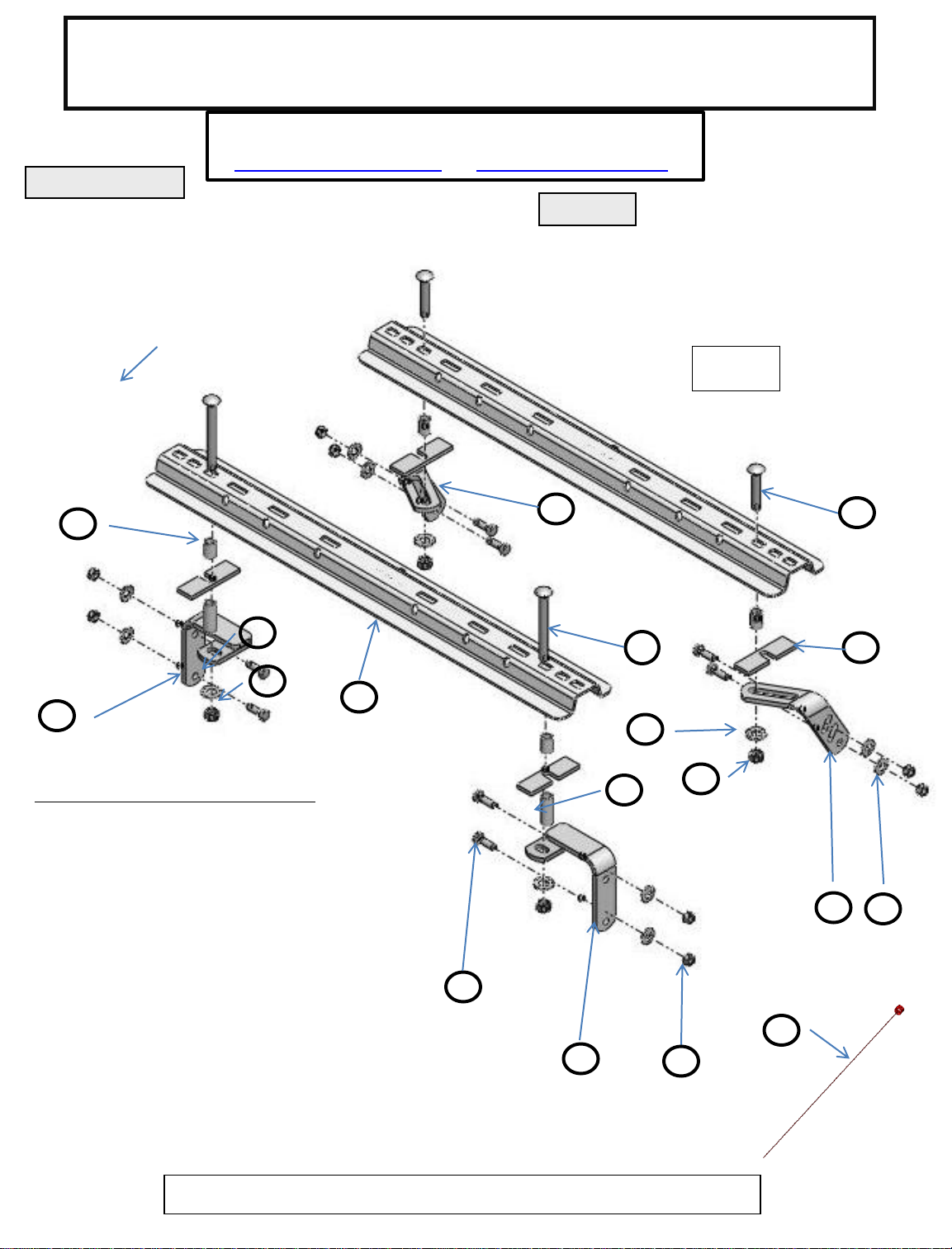
FIG. 1
10
17
16
16
BASE RAILS QTY.
1. FRAME BRACKET, FRONT LH (1)
2. FRAME BRACKET ANGLE, REAR (1)
3. FRAME BRACKET ANGLE, REAR (1)
4. 5/16” THICK FILLER SPACER (4)
5. 5/8” x 6” CARRIAGE BOLTS (2)
6. ½” KNURLED BOLTS (7)
7. 1/2” NUTS (8)
8. 1/2” SERRATED WASHERS (8)
9. 5/8” x 3-1/2” CARRIAGE BOLT (2)
10. 1-1/4” TUBE SPACER (4)
11. BASE RAILS (2)
12. 2-7/16” TUBE SPACER (2)
13. 5/8” SERRATED WASHERS (4)
14. 5/8” NUTS (4)
15. ½” PULL WIRE (4)
16. FRAME BRACKET, FRONT RH (1)
11
3
5
9
4
13
14
12
2
8
6
15
1
7
58432N 6-23-10 REV. B
NOTE: NOT ALL HARDWARE IS GOING TO BE USED ON ALL INSTALLATIONS
For Installation Assistance or Technical Help, Call 1-888-521-0510
©2010 CEQUENT PERFORMANCE PRODUCTS PRINTED IN USA
Page 2
GENERAL INSTRUCTIONS FOR 58432 ADAPTER BRACKET INSTALLATION
TOOLS
1/8" Drill 3/4" Socket & Open End Wrench 15/16” Socket 1-1/4” HOLE SAW
5/8" Drill 100 lb-ft Torque Wrench 21/32" Drill 17/32” Drill
1. The following instructions should be used to install the adapter bracket rail kit. Care and attention to detail will ensure a quick quality
installation. Check parts against parts list to become familiar with parts in kit. (See Fig. 1)
2. Raise rear of truck high enough to allow jack stands to be placed under rear spring hanger bracket of truck. This will provide maximum
room to install the 5th wheel brackets.
WARNING:
If the truck is raised, be sure that the truck is properly blocked and restrained to prevent the truck
from falling. Failure to do so may result in the truck suddenly falling, causing death or serious injury.
3. Do not install mounting rails over plastic bed liners. Plastic bed liners must be cut out of the way. Base rails may be
installed on spray in liner. Note: Consult installer for recommended curing time.
4. Use only CEQUENT PERFORMANCE PRODUCTS supplied bolts, nuts, and washers to install this kit. All bolts are grade 5 and nuts are
grade 5 unless specified otherwise.
5. Each frame bracket must be bolted to the vehicle frame with two bolts, unless optional weld is used.
CAUTION:
These instructions are guidelines only. Actual installation is the responsibility of the installer and the owner. Always measure
truck and trailer before installing hitch to be sure that there is clearance at the cab and at the bumper to allow for turns.
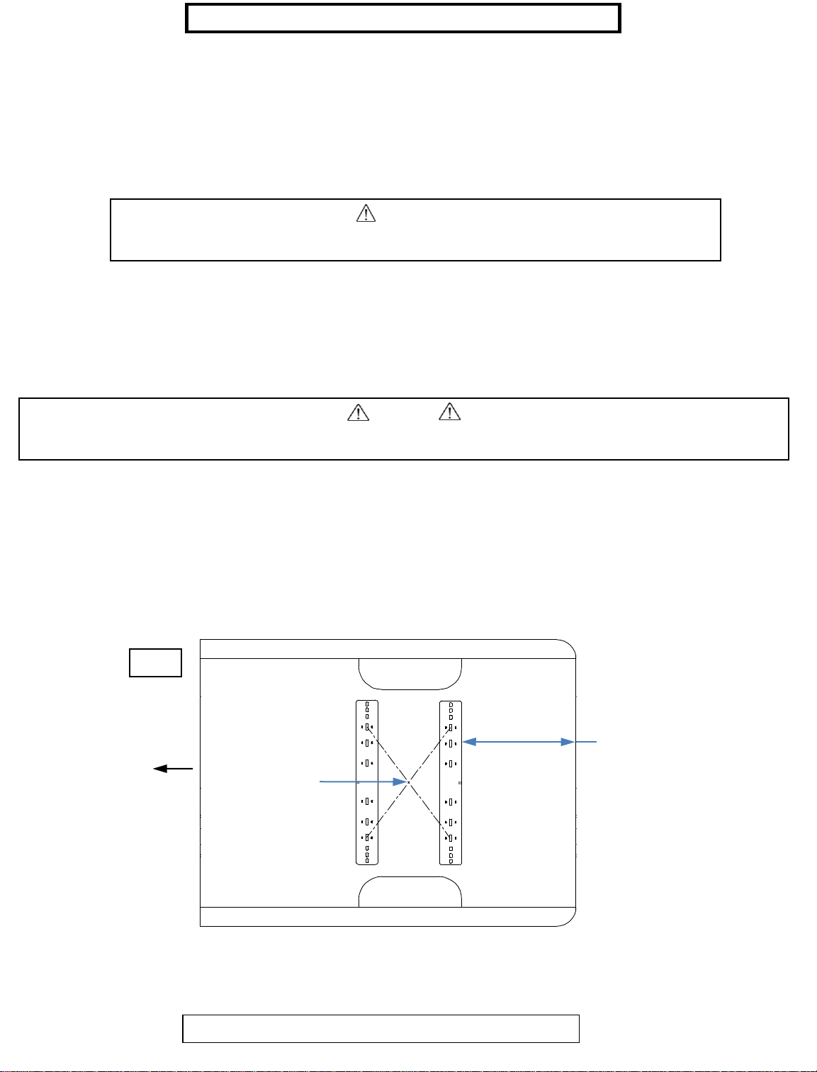
6. Measurements are given from Rear Edge of truck bed to rear edge of the base rail closest to the Rear Edge of truck for most vehicle
applications.
7. Center hitch between fender wells and make sure rails are square. Adjust position of rails until both diagonal measurements are the
same. This should allow installation of a gooseneck or other 5th wheels to these rails.
Fig. 2
Rear rail to rear edge
FRONT
Measure diagonal
from same reference
point. Measurement
of bed measurement.
26-1/4” FOR 6’ BED QUAD CAB
28-1/4” FOR 8’ BED REGULAR CAB
26-1/4” FOR 6’ BED REGULAR CAB
should be the same.
58432N 6-23-10 REV. B
For Installation Assistance or Technical Help, Call 1-800-632-3290
©2010 CEQUENT PERFORMANCE PRODUCTS PRINTED IN USA
2
Page 3

8. With the 5thwheel assembly in the bed of the truck, position the rear rail as directed in figure 2 on the previous page.
9. Drill an 1/8” hole through the bed in the inside hole locations of the front rail as shown in figure 1. This should be
approximately in the middle of the bed hat channel. Drill down through the bottom of the bed hat channel with the 1/8”
drill.
10. Place the front frame brackets under the bed to verify that the 1/8” holes align with the slots in the frame brackets. The
frame brackets should be against the rear side of the hat channel. Drill the holes in the bed to 1-1/4” with the hole saw.
Drill the hole in the bottom of the hat channel to 5/8”. See figure 1.
11. Insert 5/8” x 6” carriage bolts down through the rail. Insert the 1-1/4” tube spacer under the rail with the 5/16” thick
spacer plate. Put the 2-7/16” long spacer down into the hat channel with the 5/16” thick plate on top of it. The 5/16”
thick plate needs to be between the bed corrugations and the rails so that there is no gap under the rails. Install
serrated washers and nuts on the bolts. Hand tighten.
12. Using the holes in the frame brackets as a guide, drill 17/32” holes into the frame. Use the pull wire and an access hole
in the frame to pull rib neck bolts into the frame. Install serrated washers and nuts on the bolts. Snug up the nuts.
13. With the 5thwheel hitch in the rails, mark the hole location of the rear rail bolt locations using the inside bolt locations.
See figure 1.
14. Drill a 5/8” hole through the bed. Place a 5/16” thick spacer over the hole and the 1-1/4” tube spacer above the 5/16”
spacer. Place the rail over the spacers and insert the 5/8” x 3-1/2” carriage bolts. See figure 1.
15. Place the rear frame brackets over the 5/8” bolts. Left rear and right rear brackets can be interchanged if it makes
installation easier. Install 5/8” serrated washers and nuts on the bolts.
16. Follow step 12 to install 4 rib neck bolts into the rear frame brackets.
17. Torque all ½” nuts to 85 ft.\ lb. and all 5/8” nuts to 150 ft / lb.
OPTIONAL WELD ON APPLICATION
CAN BE USED ON ALL TRUCKS
WARNING:
DO NOT lubricate threads. It may cause bolt failure.
CAUTION:
Check for obstructions before drilling. Failure to do so could result in damaged fuel or brake lines,
structural members, etc. TOWING PRODUCTS does its best to communicate tow vehicle
manufacturer changes; however, it is ultimately the responsibility of the installer to prevent damage
due to installation.
58432N 6-23-10 REV. B
CAUTION:
It is important that 17/32" drill be used for holes in chassis frame as rib neck bolts
may break if too small a hole is used and neck may not grip if too large a hole is used.
©2010 CEQUENT PERFORMANCE PRODUCTS PRINTED IN USA
3
Page 4

THREE YEAR LIMITED WARRANTY
CEQUENT PERFORMANCE PRODUCTS warrants its 5th Wheel Hitch Mounting Kits from date of purchase against defects in material and
workmanship under normal use and service, ordinary wear and tear excepted, for 3 years of ownership to the original consumer
purchaser when a TOWING PRODUCTS mounting kit is used.
CEQUENT PERFORMANCE PRODUCTS will replace FREE OF CHARGE any part which proves defective in material or workmanship when
presented to any CEQUENT PERFORMANCE PRODUCTS dealer, CEQUENT PERFORMANCE PRODUCTS Warehouse or returned to factory.
TRANSPORTATION CHARGES PREPAID, at the address below. THIS WARRANTY IS LIMITED TO DEFECTIVE PARTS REPLACEMENT ONLY.
LABOR CHARGES AND/OR DAMAGE INCURRED IN INSTALLATION OR REPLACEMENT AS WELL AS INCIDENTAL AND CONSEQUENTIAL
DAMAGES CONNECTED THEREWITH ARE EXCLUDED.
Some states do not allow the exclusion or limitation of incidental or consequential damages, so the above limitation or exclusion may not
apply to you.
Any damage to the 5th Wheel Hitch as a result of misuse, abuse, neglect, accident, improper installation, or any use violative of
instructions furnished by us, WILL VOID THE WARRANTY.
This warranty gives you specific legal rights, and you may also have other rights which vary from state to state. In the event of a problem
with warranty service or performance, you may be able to go to a small claims court, or a federal district court.
Cequent Performance Products, Inc.
47774 Anchor Ct.
Plymouth, MI. 48170
58432N 6-23-10 REV. B
©2010 CEQUENT PERFORMANCE PRODUCTS PRINTED IN USA
4
 Loading...