

Page 1
L
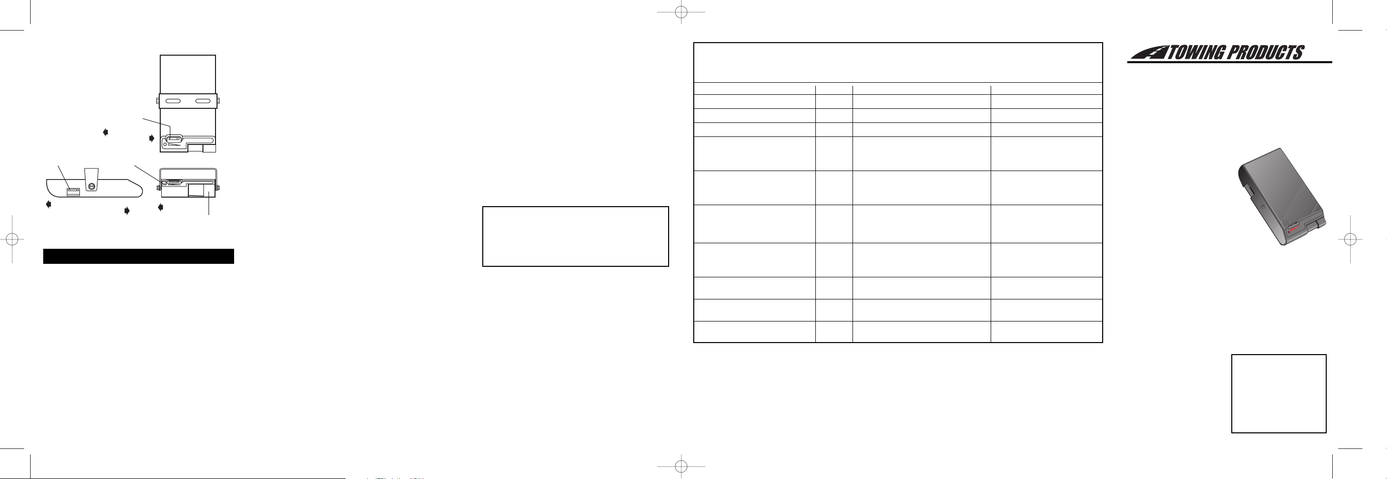
CONTROLS
OUTPUT CONTROL
The output control is located on the front of the brake
control unit at the top left side.
The output control establishes the maximum amount of
power available to the trailer brakes.
As the setting is moved to the left more power will be
available to the brakes when the brake pedal is
pressed or the manual control is used.
The output control would be adjusted when trailer load
changes, when different trailers are used or to adjust
for a change in road conditions.
SYNC CONTROL
The sync control is located on the left side of the brake
control unit, forward of the mounting bracket. The sync
control adjusts brake aggressiveness or the time it takes
to reach the full output set by the output control when the
brake pedal is pressed.
The sync adjustment has no effect on the manual control.
The brakes become more aggressive as the switch is
moved toward the front of the tow vehicle.
The sync control would be adjusted for individual driver
preference or changing road conditions.
MANUAL CONTROL
The manual control is located on the front of the brake
control unit at the right side.
The manual control only applies the trailer brakes and
would be used in situations when it is desirable to reduce
speed slowly.
When the manual control is pushed to the left the control
begins to apply the trailer brakes. The further to the left it
is pushed the harder the brakes are applied until the
maximum set by the output control is reached.
The manual control activates the tow vehicle and trailer
stoplights and the output indicator on the control unit.
OUTPUT INDICATOR
The red indicator light on the front of the control unit will
glow when brakes are applied either by the brake pedal
or the manual control (with or without a trailer attached).
The indicator will start dim and glow brighter as output
increases.
The indicator light will also help confirm proper installation.
SET UP
1. With a trailer connected, set the sync control half
way between + and -. Starting with the output
control in the lowest position (all the way right) roll
forward slowly and stop. If no trailer braking is felt
adjust the output control slightly to the left. Repeat
this process until firm trailer brakes are felt. If the
trailer brakes lock-up or jerk adjust the output
back to the right slightly.
2. Move the sync control back (toward the driver) to
about 1/4 of the distance between + and -.
3. Test drive making several stops. Adjust the sync
control until stops are smooth and firm. Slight
adjustment of the output control may also be
desirable.
Setting the brake control too aggressively
could cause brake pulsing when towing
with hazard flashers on. If such settings
are necessary, a pulse preventor can be
used.
4. Have someone watch the stoplights while the
manual control is activated to make sure the stoplights on both the tow vehicle and trailer are working.
Note: If any problems occur during set up refer to
the Trouble shooting section of these instructions.
USAGE TIPS
Light pressure on the brake pedal will activate the
trailer’s brakes with little or no effect on the tow vehicle’s brakes. This is useful for gradual slowing on
steep downhill grades or before stops.
INSTRUCTIONS FOR THE INSTALLATION
AND OPERATION OF
ELECTRONIC TRAILER BRAKE CONTROL FOR
2 AND 4 BRAKE SYSTEMS
IMP0RTANT: READ AND
FOLLOW THESE
INSTRUCTIONS CAREFULLY. KEEP THESE
INSTRUCTIONS IN YOUR
TOW VEHICLE FOR
FUTURE REFERENCE.
THIS PACKAGE INCLUDES:
(1) Brake Control Unit
(1) Mounting Bracket
(4) Mounting Screws
(1) Wire Tap Connector
(1) Warranty Card
TOOLS REQUIRED:
Assorted end wrenches
Drill with 1/8” bit
Wire connector crimp tool
Probe type circuit tester
Wire cutter/stripper
Screwdriver
MATERIAL REQUIRED:
12 Ga. or larger wire
20 Amp auto-reset circuit breaker
Assorted ring terminals
& butt connectors
4” cable ties (6-10)
Periodic adjustment of the Sync and Output controls may be necessary to correct for changing road
conditions, trailer loading, brake wear and/or driver
preference.
On some vehicles, operating the brake control’s manual
control will not disengage “Cruise Control.”
TROUBLE SHOOTING GUIDE
PROBLEM LIGHT POSSIBLE CAUSES SOLUTION
TRAILER BRAKING IS DELAYED ON INCORRECT SYNC ADJUSTMENT ADJUST TO MORE AGGRESSIVE POSITION
TRAILER BRAKES COME ON TOO FAST ON INCORRECT SYNC ADJUSTMENT ADJUST TO LESS AGGRESSIVE POSITION
TRAILER BRAKES ARE WEAK ON INCORRECT OUTPUT ADJUSTMENT ADJUST FOR MORE OUTPUT
TRAILER BRAKES COME ON TOO HARD ON INCORRECT OUTPUT ADJUSTMENT ADJUST FOR LESS OUTPUT
NO TRAILER BRAKES - PEDAL OR MANUAL OFF NO POWER TO UNIT THRU BLACK “BATTERY +” WlRE CHECK CONNECTIONS AT: BATTERY,
OPERATION CIRCUIT BREAKER, BRAKE CONTROL
OUTPUT ADJUSTED TOO LOW RE-ADJUST (SEE SET UP)
NO TRAILER BRAKES - PEDAL OR MANUAL ON NO CONNECTION TO TRAILER BRAKES THRU BLUE CHECK TRAILER CONNECTOR CONTACTS
OPERATION (BRIGHT) “BRAKE” WIRE CHECK WIRE CONNECTIONS (SEE WIRlNG)
TRAILER OR TRAILER BRAKES NOT GROUNDED CHECK TRAILER AND BRAKE GROUNDS
NO TRAILER BRAKES USING BRAKE PEDAL OFF NO CONNECTION AT STOPLIGHT SWITCH THRU RED CHECK STOPLIGHT CONNECTION
MANUAL OPERATION WORKS (PEDAL) “STOPLIGHT” WIRE (SEE WIRlNG STEP 8)
ON
(MANUAL)
TRAILER BRAKES LOCKED ON WHEN RED “STOPLIGHT” WlRE CONNECTED TO WRONG CHECK CONNECTION (SEE WIRlNG STEP 8)
CONNECTED TO CONTROL ON SIDE OF STOPLIGHT SWITCH OR TO BATTERY +
BREAK-AWAY SWITCH ACTIVATED CHECK SWITCH AND CORRECT
TRAILER BRAKES SEEM TO BE WORKING DIM OR FAULTY WHITE “GROUND” WIRE CONNECTION CHECK CONNECTIONS
FLICKERS
WEAK OR INCONSISTANT TRAILER BRAKES DIM OR SHORT IN BLUE “BRAKE” WlRE CIRCUIT LOCATE SHORT & CORRECT
FLICKERS SHORT IN TRAILER BRAKE CIRCUIT LOCATE SHORT & REPAIR
BRAKE CONTROL OVERHEATS, SMELLS DIM BLACK “BATTERY +” WIRE & WHITE “GROUND” BRAKE CONTROL UNIT DESTROYED
HOT, LOW OR NO BRAKE OUTPUT WIRE CONNECTIONS REVERSED CORRECT WIRING & REPLACE UNIT
TOWING PRODUCTS 47774
Anchor Court West
Plymouth, MI 48170
© TOWING PRODUCTS 2003
PRINTED IN CHINA
05100-037 1 of 3 rev. 1/21/03
Note: A standard voltmeter will not show true output voltage.
05100-037 1/21/03 English 3/6/03 2:00 PM Page 1
OUTPUT
CONTROL
More Output
Less Output
OUTPUT
INDICATORSYNC CONTROL
+ SYNC -
More Aggressive Braking
Less Aggressive Braking
ACTIVATOR
OUTPUT
ACTIVATOR
OUTPUT
Push to Apply
Trailer Brakes
MANUAL
CONTRO
+
SYNC–
Page 2
12 Volt Tow Vehicle Battery
BATT
AUX
20A Auto-Reset
Circuit Breaker
(Not Supplied)
This Electronic Brake Control is for Use
on 12-Volt Negative Ground Systems Only
IMPORTANT: DO NOT
REVERSE BLACK AND
WHITE WIRE CONNECTIONS!
Damage to the brake control
unit will occur!
IMPORTANT: Read and
follow all warnings and cautions
printed on tow vehicle battery.
SPECIAL INSTRUCTIONS:
For Ford E and F Series Trucks and Vans,
1989-1991 with Anti-Lock Brakes
Do NOT Connect to stoplight switch on these vehicles
Turn signal harness connector under
dash near steering column. Splice red
stoplight wire to light green wire using
the wire tap connector supplied
Light
Green Wire
Trailer
Connector
Brake Control
Battery (+) Black
Stoplight Red
Ground (–) White
Brake Blue
Wire Tap
(Supplied)
Use 12 gauge
or larger wire
Butt Connectors
(Not Supplied)
Stoplight
Switch
Connect to cold side (“On” only when brake
pedal is depressed), see wiring Step 8.
IMPORTANT: For 1989-1991
Ford E and F Series vehicles with
anti-lock brakes see Step 8 and
special instructions above.
wire and crimp type ring terminals connect the
“BATT” side of the circuit breaker to the positive
battery terminal.
3. Feed two, different colored, 12 GA or larger
stranded wires from the brake control location to
the tow vehicle battery area.
4. Connect one of the wires (noting the color) to the
“AUX” side of the circuit breaker with a ring terminal.
5. Connect the other wire to the negative battery
cable with a ring terminal.
6. Attach the control’s black “BATTERY +” wire to the
wire connected to the “AUX” terminal of the circuit
breaker using a butt connector. Make sure that the
connection is made to the correct wire (color).
7. Connect the control’s white “GROUND -” wire to
the wire leading to the negative side of the battery
with another butt connector.
WARNING: A brake control that is not properly
grounded may operate intermittently or not at all.
Make sure all connections are solid.
8. For tow vehicles other than 1989-91 Ford E and F
series trucks and vans:
Determine which side of the stoplight switch is the
cold side. To determine the cold side probe the
terminals of the switch with a test light until one is
found that is only on when the brake pedal is
depressed.
Using the wire tap provided, splice the brake control’s
red “STOPLIGHT” wire to the wire attached to the cold
side of the stoplight switch as determined above.
For 1989-91 Ford E and F series trucks and vans
with anti-lock brakes:
Find the crescent shaped connector located on the
steering column (turn signal harness). The connector
has two rows of wires, one row has four wires (inside
row) the other has seven. The wire needed is the light
green wire, second from the left in the row of seven
(see wiring diagram).
Using the wire tap provided, splice the brake control’s
red “STOPLIGHT” wire to the light green wire.
10. Secure all loose wires with cable ties so that they will
not be damaged and reconnect battery. See vehicle’s
owners manual for special reconnection instructions.
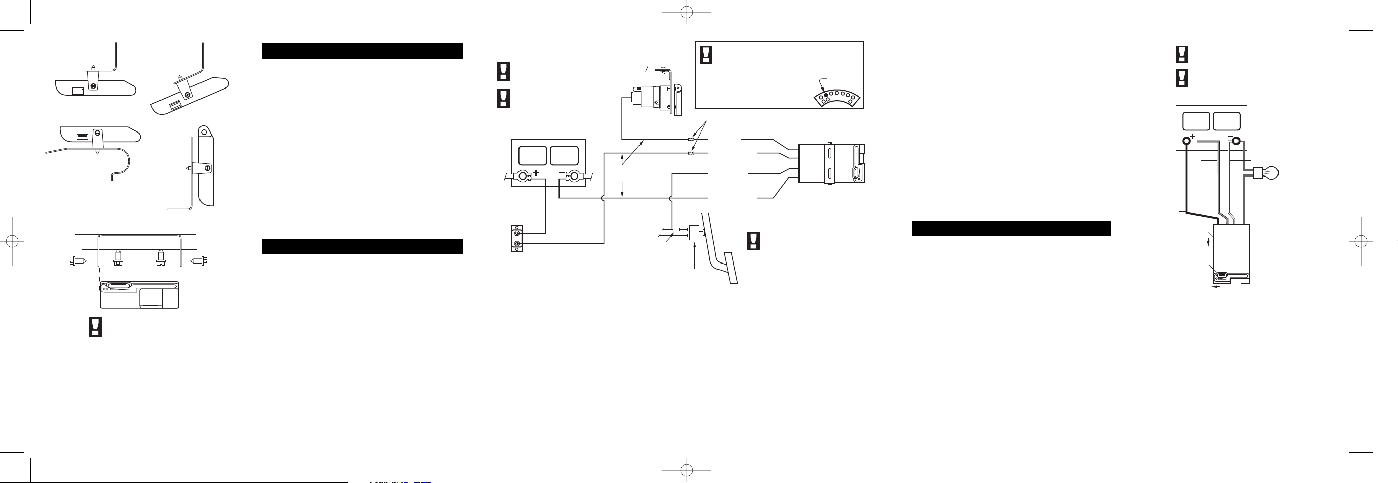
BENCH TEST INSTRUCTIONS
1. Wire as shown at right. Set Output control to maximum and the Sync control to minimum.
2. Test brake pedal activation:
While watching the test bulb, hold the red wire on the
positive (+) battery terminal.
The bulb should start dim and slowly get brighter.
The red output indicator on the brake control should
glow brightly.
Disconnect the red wire.
Adjust the Sync control to maximum (+).
While watching the test bulb, hold the red wire on the
positive (+) battery terminal.
The bulb should light brightly with no delay.
With the red wire still on the battery terminal, slide the
output control back and forth. The test bulb should
change from bright to dim with the movement of the
output control. Disconnect the red wire.
3. Test manual activation:
Set the output control to maximum.
While watching the test bulb, slowly activate the
manual control.
The test bulb should start dim and get brighter as
the manual control is pushed.
While holding the manual control all the way on,
slide the output control back and forth.
The test bulb should change from bright to dim with
the movement of the output control.
4. If the brake control does not function as described
above, return it for service or replacement.
MOUNTING
1. Determine a suitable mounting location.
A) The unit must be mounted securely to a solid
surface.
B) The unit must be easily reached by the driver.
C) The area behind the mounting location must be
clear so nothing will be damaged when drilling.
2. Hold the mounting bracket in the position selected and
mark hole locations through the slots in the bracket.
3. Using a 1/8” dia. bit, drill holes in the marked locations.
4. With a screwdriver or a 1/4” nut driver, secure the
bracket in place using (2) self tapping screws (provided). Be careful not to strip the holes by over-tightening.
5. Mount the brake control unit in the bracket using the other
(2) self tapping screws as shown in the illustration.
WIRING
WARNING: Do not connect the black “BATTERY”
wire to the fuse panel or tie into accessory wiring.
Connecting to existing wiring may damage vehicle
wiring and cause trailer brake failure.
Do not reverse black “BATTERY” wire and white
“GROUND” wire connections. Even a momentary misconnection can damage the brake control unit.
FOR TOW VEHICLES EQUIPPED WITH
FACTORY TRAILER TOWING PACKAGES:
Wire per tow vehicle manufacturer’s instructions.
FOR TOW VEHICLES WITHOUT FACTORY
TRAILER TOWING PACKAGES:
1. Disconnect the tow vehicle’s negative (-) battery cable.
2. Mount a 20 Amp auto-reset circuit breaker (such as
Draw-Tite 18051) as close to the positive (+) battery
terminal as possible. Using 12 GA or larger stranded
05100-037 1/21/03 English 3/6/03 2:00 PM Page 2
+ SYNC -
UNDER DASH
+ SYNC -
TOP OF DASH
IMPORTANT:
Make sure area behind panel
is clear before drilling!
OUTPUT
VERTICAL
ACTIVATOR
Use bracket as template to mark hole locations.
Drill two 1/8" diameter holes and mount bracket
with screws provided.
Mount brake control to bracket using the remaining
two screws.
-
SYNC
+
ANY ANGLE
IMPORTANT: Read and
follow all warnings and cautions
printed on battery.
IMPORTANT: Make sure
White wire goes to
Black wire goes to
connection will damage the
brake control unit.
12 Volt Battery
Red
Wire
Only connect
red wire when
needed. See
instructions
below.
Black
Wire
Sync
Control
Minimum (–)
Output
Control
Maximum
– and
+. Improper
White Wire
Standard 1156
Automotive Bulb
Use a socket or
solder wires to bulb.
Blue Wire
Brake
Control
Manual
Control
Page 3

INSTRUCTIONS POUR L’INSTALLATION ET
L’OPÉRATION DU
CONTRÔLE ÉLETRONIQUE DE FREINAGE POUR
REMORQUES À SYSTEMES DE 2 ET 4 FREINS
IMPORTANT: LISEZ ET
SUIVEZ TOUTES LES
INSTRUCTIONS
FIDELMENT. GARDEZLES DANS VOTRE
VÉHICULE
REMORQUEUR POUR
RÉFÉRENCE
ULTÉRIEUR.
CE NÉCESSAIRE CONTIENT
(1) Dispositif de contrôle de
freinage
(1) Support de montage
(4) Vis pour le montage
(1) Connecteur volant
(1) Fiche de garantie
OUTILS REQUIS:
Ciés diverses
Perceuse avec foret de 1/8”
Pinces pour connecteurs électriques
Vérificateur de circuit
Pinces coupe-fils/à dénuder
Tournevis
MATÉRIEL REQUIS
Néc. de câblage pour contrôle
de freins ou:
Câblage de calibre 12
Disjoncteur à réenclenchement
automatique de 20 A
Cosses à sertir et manchons
connecteurs divers
Colliers de serrage de 4” (6-10)
TOWING PRODUCTS
47774 Anchor Court West
Plymouth, MI 48170
© TOWING PRODUCTS 2003
PRINTED IN CHINA
05100-037 2 of 3 rev. 1/21/03
SECTION 1 – MONTAGE
1. Choisissez un emplacement d’installation convenable.
A) Le dispositif doit être solidement fixe à une surface
solide.
B)Le chauffeur doit avoir un accéss facile au dispositif.
C)L’espace derrière l’emplacement doit être libre de
facon à ce que rien ne soit endommagé lors du
perÇage.
2. Tenez le support de montage dans la position choisie
et marquez l’emplacement des trous au travers des
trous oblongs dans le support.
3. Au moyen d’un foret de 1/8" de diamètre, percez les
trous dans les emplacements marqués.
4. Au moyen d’un tournevis ou d’un tourne-écrous de
1/4", fixez le support en place avec les deux vis auto
taraudeuses (fournies). Faites attention de ne pas
foirer les trous en serrrant trop.
5. Montez le contrôle de freins dans le support au moyen
des deux autres vis auto taraudeuses comme montré
dans l’illustration.
SECTION 2 - CÂBLAGE
AVERTISSEMENT: Ne pas brancher le fil noir
"BATTERY" àla boîte de fusibles ou connecter au
câblage auxiliare. Un branchement au câblage
existant pourrait endommager le câblage du
véhicule ou provoquer une panne des freins de la
remorque.
Ne pas inverser les connexions du fil noir
"BATTERY" et du fil blanc "GROUND". Une mauvais
branchemente même trés bref peut endommager le
dispositif de contrôle de freins.
POUR VÉHICULES REMORQUEURS ÉQUIPÉS D’UN
DISPOSITIF DE REMORQUAGE INSTALLÉ EN
USINE:
Posez les fils selon les directives du manufacturier
du véhicule.
POUR LES VÉHICULES SANS DISPOSITIF DE
REMORQUAGE INSTALLÉ EN USINE:
1. Déterminez quel est le c
ô
t
é
mort de l’interrupteur
des feux d’arr
ê
t. Pour le trouver, faites un essai sur
les bornes de l’interrupteur au moyen d’une
lampe d’essai jusqu’
à
ce que vous trouviez une
borne qui allume seulement lorsqu’on appui sur la
pédale de frein. Marquez le câble mort.
Batterie 12-Volts Du Véhicule Remorqueur
BATT
AUX
Disjoncteur A
Réenclenchement
Automatique De
20 A (Non Fourni)
Ce Contrôle Electronique De Freins Ne Devra
Etre Utilisée Que Sur Des Systèmes De 12 Volts
Avec Mise A La Terre Négative Seulement
IMPORTANT: N'INVERSEZ PAS
LES CONNEXIONS DU CÂBLE NOIR
ET DU CÂBLE BLANC! Vous
endommageriez le dispositif de
contrôle de freins
IMPORTANT: lisez tous les avertissements
et prenez toutes les précautions imprimées
sur la batterie du véhicule remorqueur.
INSTRUCTIONS PARTICULIERES:
Pour les fourgonnettes et camions Ford de Séries
E et F 1989-1991 avec freins antiblocage:
NE CONNECTEZ PAS à l'interrupteur des feux d'arrêt
Connecteur du faisceau des clignotants sous le
tableau de bord près de la colonne de direction.
Epissez le câble rouge du feu d'arrêt au câble
vert pâle au moyen du connecteur volant fourni.
Fil vert
pâle
Connecteur
pour Remorque
Contrôle De Freins
Batterie (+), Noir
Feux d'arrêt, Rouge
Masse (-), Blanc
Frein, Bleu
Connecteur
Volant (Fourni)
Utilisez Câble De
Calibre 12 Ou Plus
Manchons Connecteurs
(Non Fournis)
Interrupteur
des feux d'arrêt
Branchez au côté "mort" (en marche
seulement si on appuie sur le pédale de
frein). Voir étape 9 du câbleage.
IMPORTANT: Pour les véhicules
Ford de Séries E et F de 1989-1991
avec freins antiblocage, voir étape 9,
iet les instructions particulières ci-dessus.
11. Fixez tous les câbles libres au moyen des colliers
de serrage de faÇon
à
ce qu’ils ne soient pas
endommagés. Rebranchez la batterie. Voir le
manuel de propriétaire du véhicule pour les
instructions particuli
è
res de rebranchement.
CONTRÔLE MANUEL
Le contrôle manuel est situédu côtédroit, sur le
devant du dispositif de contrôle de freins.
Le contrôle manuel applique seulement les freins de la
remorque et doit être utilisédans les situations où il
faut lentement r
é
duire la vitesse.
Lorsque le contrôle manuel est poussévers la gauche,
il commence àop
é
rer sur les freins de la remorque.
Plus il est pouss
é
vers la gauche, plus le freinage sera
ferme, jusqu’àatteindre la puissance maximum fixée
par le réglage du contrôle de sortie.
Le contrôle manuel actionne les feux d’arrêt du
v
é
hicule remorqueur et de la remorque ainsi que
l’indicateur de sortie du dispositif de contrôle.
INSTRUCTIONS POUR TESTS EN ATELIER
1. Posez les fils tel qu’indiqué à droite. Réglez le
contrôle de sortie à maximum et le contrôle "Sync" à
minimum.
2. Vérifiez l’activation de la pédale de frein.
Tout en surveillant la lampe d’essai, tenez le câble
rouge sur la borne positive (+) de la batterie
La lampe d’essai devrait s’allumer d’abord faiblement,
puis de plus en plus fortement.
Le voyant lumineux rouge de sortie du contrôle de
frein devrait briller.
Débranchez le câble rouge.
Ajustez le contrôle "Sync" au maximum (+).
Tout en surveillant la lampe d’essai, tenez le fil rouge
sur la borne positive (+) de la batterie.
La lampe d’essai devrait s’allumer fortement sans
délai.
Tout en maintenant le fil rouge sur la borne de la
batterie, faites aller et venir le controle de sortie.
La lampe d’essai devrait suivre le mouvement du
contrôle de sortie, passant d’éclairage fort à faible.
Débranchez le câble rouge.
3. Vérifiez l’activation manuelle:
Réglez le contrôle de sortie à maximum.
Tout en surveillant la lampe d’essai, activez lentement
le contrôle manuel.
La lampe d’essai devrait éclairer d’abord faiblement,
puis de plus en plus fort.
Tout en maintenant le contr
ô
le manuel en mode actif,
faites aller et venir le contr
ô
le de sortie.
La lampe d’essai devrait suivre le mouvement du
contrôle de sortie, passant d’éclairage fort à faible.
4. Si le contr
ô
le de freins ne fonctionne pas comme
expliqué ci-dessus, renvoyez-le pour réparation ou
faites-le remplacer.
Fig. 2
Fig. 2a
e
Fig. 4
05100-037 1/21/03 French 3/6/03 2:01 PM Page 1
+
SYNC–
IMPORTANT: Lisez tous les
avertissements et prenez toutes les
précautions imprimées sur la batterie.
IMPORTANT: Assurez-vous que le
câble Blanc va à (-) et que le câble noir
va à (+). Une mauvaise connexion
endommagera le contrôle de freins.
Batterie 12 V
Câble
Rouge
Connectez le
câble rouge
seulement
quand il y a
besion. Voir
les instructions
à gauche.
Câble
Noir
Contrôle
Sync
Minimum (–)
Contrôle
De Sortie
Maximum
Câble Blanc
Lampe standard d'auto
1156. Utilisez une douill
ou soudez le câbles à
la lampe
Câble Bleu
Contrôle
De Freins
Contrôle
Manuel
Page 4

GUIDE DE LOCALISATION DE LA PANNE
PROBLEME VOYANT CAUSES POSSIBLES SOLUTION
FREINAGE DIFFÉRÉ DE LA REMORQUE OUI MAUVAIS RÉGLAGE DU CONTRÔLE <<SYNC>>
AJUSTER EN POSITION PLUS AGRESSIVE
FREINAGE DE LA REMORQUE TROP RAPIDE OUI MAUVAIS RÉGLAGE DU CONTRÔLE <<SYNC>>
AJUSTER EN POSITION MOINS AGRESSIVE
FREINS DE LA REMORQUE TROP FAIBLES OUI MAUVAIS RÉGLAGE DU CONTRÔLE DE SORTIE AJUSTER POUR PUISSANCE ACCRUE
FREINS DE LA REMORQUE TROP RIGIDES OUI MAUVAIS RÉGLAGE DU CONTRÔLE DE SORTIE AJUSTER POUR PUISSANCE RÉDUITE
PAS DE FREINAGE DE LA REMORQUE PAR NON
PAS DE COURANT AU DISPOSITIF DE CONTRÔLE DE
VÉRIFIER CONNEXIONS À LA BATTERIE, AU DISJONC-
LA PÉDALE OU EN MODE MANUAL
FREINS EN PROVENANCE DU FIL NOIR + DE LA BATTERIE
TEUR, ET AU DISPOSITIF DE CONTRÔLE DE FREINS
R
ÉGLAGE DU CONTRÔLE DE SORTIE TROP BAS
REPRENDRE LES RÉGLAGES (VOIR RÉGLAGES)
PAS DE FREINAGE DE LA REMORQUE PAR OUI (VIF) PAS DE CONEXION AUX FREINS DE REMORQUE
VÉRIFIER CONTACTS DE CONNEXION DE REMORQUE
LA PÉDALE OU EN MODE MANUAL À TRAVERS LE CÂBLE BLEU <<BRAKE>>
VÉRIFIER CONNEXIONS DE CÂBLAGE (VOIR CÂBLAGE)
REMORQUE OU FREINS DE REMORQUE NE SONT
PAS MISES À LA MASSE
VÉRIFIER MISE À LA MASSE
PAS DE FREINAGE DE LA REMORQUE PAR
NON
PAS DE CONNEXION À L’INTERRUPTEUR DES FEUX
VÉRIFIER CONNEXION DE FEUX D’ARRET
LA PÉDALE DE FREINAGE EN MODE MANUEL (PÉDALE)
D’ARRET EN PROVENANCE DU CÂBLE ROUGE <<STOPLIGHT>>
(VOIR CÂBLAGE À L’ÉTAPE 9)
OUI
(MANUEL)
FREINS DE REMORQUE BARRÉS LORSQUE
CÂBLE ROUGE <<STOPLIGHT>> EST CONNECTÉ AU MAUVAIS
VÉRIFIER LA CONNEXION
CONNECTÉS AU CONTRÔLE OUI
CÔTÉ DE L’INTERRUPTOR DES FEUX D’ARRET OU DE LA BATTERIE
(VOIR CÂBLAGE À L’ÉTAPE 9)
INTERRUPTEUR DE D
ÉTACHEMENT ACTIVÉ
VÉRIFIER L’INTERRUPTOR ET CORRIGER
LES FREINS DE REMORQUE SEMBLENT OPÉRER
FAIBLE OU
CONNEXION DE MISE À LA TERRE (CÂBLE BLANC VÉRIFIER LES CONNEXIONS
VACILLANT
<<GROUND>>) DÉFECTUEUSE
FREINAGE DE REMORQUE FAIBLE OU INTERMITTENT FAIBLE OU
COURT-CIRCUIT DE LA CONNEXION DU CÂBLE BLEU <<BRAKE>> DE FREINAGE
REPÉRER ET RÉPARER LE COURT-CIRCUIT
VACILLANT
COURT-CIRCUIT DANS LE CIRCUIT DE FREINAGE DE LA REMORQUE
REPÉRER ET RÉPARER LE COURT-CIRCUIT
SURCHAUFFE DU CONTRÔLE DE FREINS, SENT LE
FAIBLE CONNEXIONS DE CÂBLE NOIR À LA BATTERIE ET
DISPOSITIF DE CONTRÔLE DE FREINS DÉTRUIT CORRIGER
CHAUFFÉ, PEU OU PAS DE PUISSANCE DE FREINAGE
DU CÂBLE BLANC DE MISE À LA TERRE INVERSÉES
LES CONNEXIONES ET REMPLACER LE DISPOSITIF
2. Débranchez le câble négatif (-) de la batterie du
véhicule remorqueur.
3. Installez un disjoncteur àréenclenchement
automatique de 20 A aussi près que possible de la
borne positive (+) de la batterie. Au moyen d’un
câble de calibre 12 ou plus et d’une cosse àsertir
fermée, branchez le côté"BATT" du disjoncteur àla
borne positive de la batterie.
4. Acheminez un câble blanc et un câble noir de calibre
12 ou plus àpartir de l’emplacement du côntrole de
frein jusqu’àl’emplacement de la batterie du véhicule
remorquer.
5. Branchez le câble noir au côté"AUX" du disjoncteur
au moyen d’une cosse àsertir fermée.
6. Branchez le câble blanc au câble négatif de la
batterie au moyen d’une cosse àsertir fermée.
7. Reliez le câble noir "BATTERY +" du côntrole au
câble (noir) branchéàla borne "AUX" du disjoncteur
au moyen d’un manchon connecteur.
8. Connectez le câble blanc "GROUND" du c
ô
ntrole de
frein au câble blanc provenant du câble négatif de la
batterie au moyend’un autre manchon connecteur.
IMPORTANT: un contr
ô
le de freins qui n’est pas
bien mis àla terre peut opérer par intermittences
ou pas du tout. Revérifiez afin de vous assurer que
le câble blanc "GROUND" est connect
éà
la borne
n
é
gative de la batterie et que le câble noir
"BATTERY +" est reli
é
au câble positif de la
batterie.
9. Pour tous le véhicules remorqueurs sauf les
fourgonnettes et les camions Ford, Séries E et F,
1989-91:
Au moyen du connecteur volant fourni, épissez le
câble rouge "STOPLIGHT" du contrôle de freins au
câble reliéau c
ôté
mort del’interrupteur des feux
d’arr
ê
t, tel que décrit a l’
é
tape 1. Allez àl’étape 10.
Pour les fourgonnettes et camions Ford S
é
rie E
et F de 1989-91 avec freins antiblocage: voir la
fig. 2a.
Rep
é
rez le connecteur en forme de croissant sur la
colonne de direction (faisceau de clignotants). II y a 2
rang
é
es de câbles dansce connecteur, une rangée
de 4 câbles (rangée intérieure) et l’autre en a 7. Vous
avez besoin du vert pâle qui est le deux i
è
me
à
partir
de la gauche dans la rang
é
e de 7 câbles (voir la
Fig. 2a).
Au moyen du connecteur volant fourni,
é
pissez le
câble rouge "STOPLIGHT" du c
ô
ntrole de freins au
câble vert pâle.
10. Branchez le câble bleu "BRAKE" du côntrole de
freins au câble de freins de remorque.
CONTRÔLE DE SORTIE
Le contrôle de sortie est situé sur le devant du dispositif
de contrôle de freins, du côté supérieur gauche.
Le contrôle de sortie définit la quantité maximum de
courant disponible pour les freins de la remorque.
Plus le réglage est déplacé vers la gauche, plus il y a de
courant disponible pour les freins lorsqu’on appuie sur la
pédale de freins ou que le contrôle manuel est utilisé.
II faudra ajuster le contrôle de sortie si le chargement de
la remorque augmente, lorsque différentes remorques
sont tirées ou selon les conditions routières.
CONTRÔLE <<SYNC>>
Le contrôle <<sync>> est du côté gauche du dispositif
de contrôle de freins, devant le support de montage. Le
contrôle <<sync>> ajuste l’agressivité du freinage, ou le
temps nécessaire pour atteindre toute la puissance fixée
par le réglage du contrôle de sortie lorsqu’on appuie sur
la pédale de freins.
L’ajustement <<sync>> n’a aucun effet sur le contrôle
manuel.
Les freins seront plus agressifs selon que I’interrupteur
est déplacé vers I’avant du véhicule remorqueur.
Le contrôle <<sync>> sera ajusté selon les préférences
de chaque chauffeur ou selon les conditions routières.
VOYANT DE SORTIE
Le voyant rouge sur le devant du dispositif de contrôle
s’allumera lorsque les freins seront appliqués soit en
utilisant la pédale de frein soit par le contrôle manuel
(avec ou sans remorque attachée). Le voyant sera de
plus en plus brillant au fur et àmesure que la
puissance déployée augmentera.
Le voyant pourra aussi confirmer que l’installation est
conforme.
RÉGLAGES
1. Avec une remorque attachée, fixez le contrôle
<<sync>> àmi-chemin entre + et -. Avec au départ
le contrôle de sortieàla plus faible demande
(conplètemente àdroite), avancez lentement et
arrêtez. Si aucun freinage de la remorque n’est
perÇu, déplacez le contrôle de sortie légèrement
vers la gauche. Répétez l’opération jusqu’àce qu’un
freinage ferme s’applique. Si les freins de la
remorque bloquent ou s’appliquent par à-coups,
ramenez le contrôle de sortie vers la droite
légèrement.
2. Ramenez le contrôle <<sync>> (vers le chauffeur)
sur environ le 1/4 du distance entre le + et -.
3. Faites un essai en faisant plusieurs arrêts. Ajustez
le contrôle <<sync>> jusqu’àce que les arrêts se
fassent fermement et en douceur. Un ajustement
minime du contrôle de sortie peut aussi être
souhaitable.
4. Demandez àquelqu’un de v
é
rifier que les feux
d’arrêt du v
é
hicule et de la remorque fonctionnent
bien lorsque le contrôle manuel est utilisé.
Note: si des problèmes surgissent pendant les
réglages, référez-vous àla section de Localisation
de la Panne de ces instructions.
TRUCS
Une pression légère sur la p
é
dale de frein n’aura que
peu ou pas d’effet sur les freins du véhicule
remorqueur. Ceci est utile pour ralentir graduellement
dans les pentes abruptes ou avant d’arrêter.
Fig. 1
Fig. 3
L’ajustement périodique des contrôles de sortie et <<sync>> peut être nécessaire pour s’adapter aux changement des conditions routières, de
chargements de la remorque, de l’usure des freins ou des préférences du chauffeur.
Sur certains véhicules, le contrôle manuel de freins ne désengagera pas le pilote automatique.
Note: Un voltmètre standard ne montera pas le véritable voltage à la sortie
SECTION 3 - CONTRÔLES
05100-037 1/21/03 French 3/6/03 2:01 PM Page 2
+ SYNC -
EN DESSOUS DU
TABLEAU DE BORD
+ SYNC -
EN DESSUS DU
TABLEAU DE BORD
VERTICAL
OUTPUT
IMPORTANT:
Avant de percer, assurez-vous
que l'espace derrière le panel
soit libre!
Utilisez le support en guise de modèle
pour marquer l'emplacement de trous.
Percez deux trous de 1/8" de diamètre
et montez le support avec les vis fournies.
Montez le contrôle de freins sur le support
au moyen des deux vis restantes.
-
SYNC
+
N'IMPORTE
QUEL ANGLE
CONTRÔLE
CONTRÔLE SYNC
+ SYNC -
Freinage plus agressif
Freinage moins agressif
DE SORTIE
Plus de Sortie
Moins de Sortie
VOYANT
DE SORTIE
OUTPUT
OUTPUT
Appuyez pour
faire marcher
les freins
CONTRÔLE
MANUEL
Page 5

INSTRUCCIONES PARA LA INSTALACION Y
OPERACION DEL
CONTROL DE FRENO ELECTRONICO PARA
REMOLQUES CON SISTEMAS DE 2 Y 4 FRENOS
IMPORTANTE: LEA Y
SIGA CUIDADOSAMENTE ESTAS
INSTRUCCIONES.
GUARDE ESTAS
INSTRUCCIONES EN SU
VEHICULO DE
REMOLQUE PARA REFERENCIA FUTURA.
ESTE PAQUETE INCLUYE:
(1) Unidad de Control de Freno
(1) Soporte de Montaje
(4) Tornillos de Montaje
(1) Conector para Conexion de Cable
(1) Tarjeta de Garantia
HERRAMIENTAS NECESARIAS:
Llaves de diferentes calibres
Taladro con mecha de 1/8" (3,175mm)
Herramienta para plegar conectores de cable
Probador de circuitos con probadores
Cortador/pelador de cables
Destornillador o dado de 1/4"
MATERIALES NECESARIOS:
Juego de Cables para Control
de Freno o:
Cable de calibre 12 o mayor
Cortacircuitos de tipo de
reposicion de 20 amperios
Varios conectores de anillo y
dobles (6-10) Amarres de cable
de 4" (101,6 mm)
TOWING PRODUCTS
47774 Anchor Court West
Plymouth, MI 48170
© TOWING PRODUCTS 2003
PRINTED IN CHINA
05100-037 3 of 3 rev. 1/21/03
SECCIÓN 1 – INSTALACIÓN
1. Encuentre un lugar apropiado para la instalación
A) La unidad debe ser instalada firmemente a una
supsuperficie sólida.
B) La unidad debe estar en un lugar de acceso fácil para
el conductor.
C) El área detrás del lugar de montaje debe estar libre
de objetos, de manera que nada se dañe al hacer los
huecos con el taladro.
2. Sostenga el soporte de montaje en la posición
deseada y marque la posición de los agujeros usando
los agujeros del soporte como guía.
3. Use una mecha de 1/8" (3,175 mm) de diámetro y
taladre los agujeros en los lugares previamente
marcados.
4. Con un destornillador o un dado de 1/4", asegure el
soporte en su lugar usando (2) tornillos autoroscantes
(se proveen). Tenga cuidado de no barrer la rosca al
apretar los tornillos.
5. Instale la unidad de control de freno en el soporte
usando los otros (2) tornillos autoroscantes, así como
se ilustra.
SECCIÓN 2 CABLEADO
ADVERTENCIA: No conecte el cable negro
"BATTERY" al panel de fusibles o al corriente del
cableado de accesorios. Al conectarlo al cableado
existente puede dañar el cableado del vehículo y
causar fallas en los frenos del remolque.
No intercambie las conexiones del cable negro
"BATTERY" y el blanco "GROUND" (TIERRA). La
más mínima conexión momentánea errada puede
dañar la unidad de control de freno.
EN VEHíCULOS QUE TIENEN EQUIPO DE
REMOLQUE DE FÁBRICA:
Haga el cableado de acuerdo a las instrucciones del
fabricante del vehículo de remolque.
EN VEHICULOS QUO NO TIENEN EQUIPO DE
REMOLQUE DE FÁBRICA:
1. Determine cuál lado (terminal) del interruptor de
la luz de freno es el lado muerto. Para determinar
el lado muerto, use una luzde prueba, conéctela
Batería de 12V del Vehículo de Remolque
BATT
AUX
Cortacircuitos de
tipo de reposición
de 20 amperios
(No se provee)
Este Control De Freno Electrónico Debe Ser
Usado Solamente En sistemas De 12 Voltios
Con Negativo A Tierra.
IMPORTANTE: ¡NO INTERCAMBIE
LAS CONEXIONES DE LOS
CABLES BLANCO Y NEGRO!
Esto dañará la unidad de control
de freno.
IMPORTANTE: Lea y siga todas las
fadvertencias y precauciones impresas
en la batería del vehículo de remolque.
INSTRUCCIONES ESPECIALES:
Para camionetas cerradas y camiones Ford (1989-
1991) de la serie E y F con frenos antibloqueantes
En estos vehículos NO CONECTE NADA al interruptor de la luz de freno
El conector que tiene forma de creciente debajo
de la comumna de dirrección (manojo de cables de
las diagonales). Usando el conector a corriente
que se provee, una el cable rojo de control de
freno "STOPLIGHT" (LUZ DE FRENO) al cable
de color verde claro.
Cable
Verde Claro
Conector
del Remolque
Control de Freno
Batería (+) Negro
Luz de Freno Rojo
Tierra (–) Blanco
Freno Azul
Conector a
corriente (Se provee)
Use cable de
calibre 12 o mayor
Conectores Dobles
(no se proveen)
Interruptor de
la luz de freno
Conecte el lado muerto (el que está prendido
solamente cuando el pedal de freno está
presionadso), vea el paso de cableado 9.
IMPORTANTE: Para vehículos Ford
(1989-1991) de la serie E y F con freno
antibloqueantes, vea el paso 9 y las
instrucciones especiales de ariba
lado muerto del interruptor de luz de freno, ya
determinado en el paso 1. Vaya al paso 10.
En camionetas cerradas y camiones Ford
(1989-91) de las series E y F con frenos
antibloqueantes: (Vea la Fig. 2a)
Busque el conector que tiene forma de creciente
debajo de la columna de dirección (manojo de
cables de las diagonales). El conector tiene dos
hileras de cables, una hilera tiene cuatro cables
(hilera interna) y la otra siete.
El cable que se busca es el de color verde claro,
es el segundo de izquierda a derecha en la hilera
de siete cables (vea la Fig.2a)
Usando el conector a corriente que se provee, una
el cable rojo "STOPLIGHT" (LUZ DE FRENO) del
control de freno al cable de color verde claro.
CONTROL DE SINCRONIZACIÓN
El control de sincronización se encuentra localizado en
el lado izquierdo de la unidad de control de freno,
delante del soporte de montaje. El control de
sincronización ajusta la agresividad del freno o el
tiempo que le toma al freno para alcanzar la ganancia
máxima establecida por el control de ganancia cuando
el pedal del freno es presionado.
El ajustar el control de sincronización no tiene efecto
sobre el control manual.
Los frenos se vuelven más agresivo a medida que el
interruptor es movido hacia el frente del vehículo de
remolque.
El control de sincronización deberá ser ajustado de
acuerdo a la preferencia del conductor o al cambio de
las condiciones de la carretera.
que las paradas sean suaves y firmes. Puede que
sea necesario también ajustar un poquito el control
de ganancia.
4. Pídale a alguien que observe las luces de freno
mientras el control manual está activado para así
asegurarse de que las luces de frenado estén
funcionando tanto en el vehículo remolcador como
en el remolque.
Nota: Si ocurren algunos problemas durante el
ajuste, vea la sección de localización de fallas de
éstas instrucciones.
RECOMENDACIONES DE USO
Presión leve en el pedal del freno activará los frenos
del remolque con poco o ningún efecto sobre los
frenos del vehículo de remolque. Esto es necesario
cuando se quiere disminuir la velocidad gradualmente
en una bajada inclinada o antes de paradas.
INSTRUCCIONES DE PRUEBA
EN MESA DE TRABAJO
1. Conecte los componentes así como se ilustra en la
derecha. Ajuste el control de Ganancia al máximo y el
control de Sincronización al minimo.
2. Pruebe la activación del pedal de freno.
Mientras observa el bombillo de prueba, sostenga el
cable rojo en el terminal positivo (+) de la batería.
El bombillo debe prender con una luz opaca y poco a
poco aumentar en brillantez.
El indicador de ganancia (rojo) que se encuentra en el
control de freno debe resplandecer de manera
brillante.
Desconecte el cable rojo.
Ajuste el control de Sincronización al máximo.
Mientras observa el bombillo de prueba, sostenga el
cable rojo en el terminal positivo (+) de la batería.
El bombillo debe prender de manera brillante
inmediatamente.
Con el cable rojo aún en el terminal de la batería,
ajuste el control de ganancia hacia adelante y hacia
atrás. El bombillo de prueba deberá cambiar de
3. Prueba de activación manual:
Ajuste el control de ganancia al máximo.
Mientras observa el bombillo de prueba, active
lentamente el control manual.
El bombillo de prueba debe prender con una luz
opaca y poco a poco aumentar en brillantez a
medida que el control manual es movido.
Mientras tiene el control manual ajustado al máximo,
deslice el control de ganancia hacia adelante y
hacia atrás.
El bombillo de prueba deberá cambiar de brillante a
opaco con el movimiento del control de ganancia.
4. Si la unidad de Control de Freno no funciona como
se ha descrito arriba, regrésela para ser reparada o
reemplazada.
Fig. 2
Fig. 2a
Fig. 4
05100-037 1/21/03 Spanish 3/6/03 2:03 PM Page 1
+
SYNC–
IMPORTANTE: Lea y siga todas
las advertencias y precauciones
impresas el la batería
IMPORTANTE: Asegúrese de que el
Blanco vaya conectado al (-) y de que
el Negro vaya al (+). Malas conexiones
dañarán la unidad de control de freno.
BATERÍA DE 12 VOLTIOS
Cable
Rojo
Conecte el
cable rojo
solo cuando
sea necessario
Vea las
instrucciones
en la izquierda
Cable
Negro
Control de
Sincronización
Minimo (–)
Control de
Ganancia
Máximo
Cable Blanco
Automotriz Común #1156.
Use un enchufe o suelde
los cables al bombillo
Cable Azul
Control
de Freno
Control
Manual
Page 6

GUÍA DE LOCALIZACIÓN DE FALLAS
PROBLEMA LUZ POSIBLES CAUSAS SOLUCIÓN
EL FRENADO DEL REMOLQUE ES LENTO ENCENDIDA AJUSTE INCORRECTO DE SINCRONIZACIÓN
ADJúSTELO A UNA POSICIÓN MÁS AGRESIVA
LOS FRENOS DEL REMOLQUE SE ACTIVAN MUY RÁPIDO
ENCENDIDA AJUSTE INCORRECTO DE SINCRONIZACIÓN
ADJúSTELO A UNA POSICIÓN MENOS AGRESIVA
EL FRENADO DEL REMOLQUE ES DÉBIL ENCENDIDA AJUSTE INCORRECTO DE GANANCIA INCREMENTE LA GANANCIA
EL FRENADO DEL REMOLQUE ES MUY FUERTE ENCENDIDA AJUSTE INCORRECTO DE GANANCIA DISMINUYA LA GANANCIA
EL REMOLQUE NO FRENA--AL USAR EL PEDAL APAGADA
LA UNIDAD NO ESTÁ RECIBIENDO VOLTAJE A TRAVÉS
REVISE LAS CONEXIONS EN: LA BATERÍA, EL
O EL CONTROL MANUAL
DEL CABLE NEGRO “BATTERY”
CORTACIRCIOTOS Y EL CONTROL DE FRENO
LA GANANCIA AJUSTADA A UN NIVEL MUY BAJO
REAJUSTE (VEA AJUSTE)
EL REMOLQUE NO FRENA--AL USAR EL PEDAL ENCENDIDA
NO HAY CONEXIÓN A LOS FRENOS DEL REMOLQUE A TRAVÉS DEL
REVISE LOS CONTACTOS DEL CONECTOR DEL REMOLQUE
O EL CONTROL MANUAL (BRILLANTE)
CABLE CABLE AZUL “BRAKE” (FRENO)
REVISE LAS CONEXIONES DE LOS CABLES (VEA EL CABLEDO
EL REMOLQUE O LOS FRENOS DEL REMOLQUE NO TIENEN
REVISE LAS CONEXIONES A TIERRA DEL REMOLQUE Y DE
CONEXIÓN A TIERA
LOS FRENOS
EL REMOLQUE NO FRENA AL USAR EL PEDAL DEL
APAGADA NO HAY LA CONEXIÓN ENTRE EL INTERRUPTOR DE
REVISE LA CONEXIÓN DE LA LUZ DE FRENO
FRENO, EL CONTROL MANUAL FUNCIONAE (PEDAL) LUCES D FRENO Y EL CABLE ROJO “STOPLIGHT”
(VEA CABLEADO PASO 9)
PRENDIDA
(MANUAL)
LOS FRENOS DEL REMOLQUE SE TRANCAN
EL CABLE ROJO “STOPLIGHT” ESTÁ CONECTADO AL LADO
REVISE LA CONEXIÓN (VEA CABLEADO PASO 9)
CUANDO SE CONECTAN AL CONTROL ENCENDIDA
EQUIVOCADO DEL INTERRUPTOR DE LUZ DE FRENO O A LA BATERÍA
EL INTERRUPTOR DE SEPARACIÓN ESTÁ ACTIVADO
REVISE EL INTERRUPTOR Y CORRIJA EL PROBLEMA
LOS FRENOS DEL REMOLQUE PARECE QUE
PÁLIDA O
MALA CONEXIÓN DEL CABLE BLANCO “GROUND” REVISE LAS CONEXIONES
ESTÁN FUNCIONANDO
INCONSTANTE
EL FRENADO DEL REMOLQUE ES DÉBIL O INCONSISTENTE
PÁLIDA O
HAY UN CORTO EN EL CIRCUITO DEL CABLE AZUL “BRAKE” (FRENO)
LOCALICE EL CORTO Y CORRÍJALO
INCONSTANTE
HAY UN CORTO EN EL CIRCUITO DEL FRENO DEL REMOLQUE
LOCALICE EL CORTO Y REPÁRELO
EL CONTROL DE FRENO SE RECALIENTA, HUELE A
PALIDA
LAS CONEXIONS DEL CABLE NEGRO “BATTERY +” Y EL
LA UNIDAD DE CONTROL DE FRENO SE HA DAÑADO, CORRIJA
QUEMADO, HAY POCA O NINGUN POTENCIA DE FRENADO
BLANCO (-) “GROUND” SE ENCUENTRAN INTERCAMBIADAS
EL PROBLEMA DEL CABLEADO Y REEMPLACE LA UNIDAD
a un terminal del interruptor y presione el pedal del
freno, repita este procedimiento en el otro terminal.
El lado muerto será aquel terminal en el cual la luz
se encienda cuando el pedal de freno esté
presionado.
2. Desconecte el terminal negativo (-) de la batería
del vehículo.
3. Instale un cortacircuitos de tipo de reposición de 20
amperios tan cerca como sea posible al terminal
positivo (+) de la batería. Use un cable de cordón de
calibre 12 o mayor y pliegue (2) terminales de anillo
al mismo. Use este cable para conectar el lado que
dice "BATT" del cortacircuitos al terminal positivo (+)
de la batería.
4. Conecte un cable de cordón negro y otro blanco, de
calibre 12 o mayor, desde el lugar de instalación del
control de freno hasta el área de la batería del
vehículo de remolque.
5. Conecte el cable negro al lado "AUX" del
cortacircuitos usando un terminal de anillo.
6. Conecte un terminal de anillo al cable blanco y
conéctelo al cable negativo de la batería.
7. Una el cable negro de control "BATTERY +" al
cable (negro) conectado al terminal "AUX" del
cortacircuitos, use un conector doble.
8. Conecte el cable de control blanco "GROUND"
(TIERRA) al cable (blanco) que va conectado al
lado negativo de la batería, use un conector
doble.
ADVERTENCIA: Un control de freno que no está
conectado a tierra adecuadamente puede que no
funcione o que funcione de manera intermitente.
Revise el cable blanco "GROUND" (TIERRA) y
asegúrese de que está conectado al cable negative
(-) de la batería y de que el cable negro "BATTERY
(+)" está conectado al cable positivo (+) de la
batería.
9.
En vehículos de remolque diferentes a las
camionetas cerradas o camiones Ford de las
series E y F de 1989-91:
Usando el conector a corriente que se provee, una el
cable rojo "STOPLIGHT" (LUZ DE FRENO) del
control de freno al cable que se encuentra unido al
10. Conecte el cable azul "BRAKE" (FRENO) al cable de
freno del remolque.
11. Para evitor daño o maltrato a los cables, asegure
todos los cables que se encuentren guindando
usando los amarres que se proveen. Reconecte la
batería.
Refiérase al manual de instrucciones de
vehículo para obtener las instrucciones
especiales de reconexión.
SECCIÓN 3 - CONTROLES
CONTROL DE GANANCIA
El control de ganancia se encuentra localizado en
la parte frontal de la unidad de control de freno, en la
parte superior izquierda.
La función del control de ganancia es la de establecer el
monto máximo de potencia disponible para los frenos
del remolque.
Si el control es movido hacia la izquierda, más potencia
estará disponible para los frenos cuando el pedal del
freno sea presionado o cuando el control manual sea
usado.
El control de ganancia deberá ser ajustado cuando el
peso de la carga varíe, cuando diferentes remolques
sean usados o cuando las condiciones de la carretera
cambien.
CONTROL MANUAL
El control manual se encuentra localizado al lado
derecho de la parte frontal de la unidad de control de
freno.
El control manual se aplica solamente a los frenos del
remolque y debería ser usado cuando se desee reducir
la velocidad lentamente.
Cuando el control manual es movido hacia la
izquierda, el control comienza a activar los frenos del
remolque. A medida que se mueva más hacia la
izquierda, los frenos serán aplicados de manera más
fuerte hasta que se llegue al nivel máximo establecido
por el control de ganancia.
El control manual activa las luces de freno del vehículo
de remolque, del remolque y el indicador de ganancia
que se encuentra en la unidad de control.
INDICDOR DE GANANCIA
La luz indicadora roja que se encuentra en el frente de
la unidad de control se encenderá cuando los frenos
sean aplicados ya sea usando el pedal del freno o el
control manual (con o sin el remolque unido al
vehículo). El indicador producirá un brillo opaco y
luego aumentará a medida que la ganancia aumente.
La luz indicadora también ayudará a confirmar que la
instalación ha sido hecha apropiadamente.
AJUSTE
1. Con el remolque conectado, ajuste el control de
sincronización en el medio de (+) y (-). Comenzando
con el control de ganancia en la posición más baja
(todo hacia la derecha) muévalo hacia adelante
lentmente y luego pare. Si no siente que los frenos
están siendo aplicados, ajuste el control de
ganancia un poquito hacia la izquierda. Repita este
procedimiento hasta que sienta que los frenos del
remolque están siendo aplicados firmemente. Si los
frenos del remolque se trancan o tironean, ajuste
otra vez la ganancia un poquito hacia la derecha.
2. Mueva el control de sincronización hacia atrás
(hacia el conductor) aproximadamente a π de la
distancia entre (+) y (-).
3. Realice un manejo de prueba haciendo varias
paradas. Ajuste el control de sincronización hasta
+ SYNC -
OUTPUT
OUTPUT
CONTROL DE
GANANCIA
Más Ganancia
Menos Ganancia
INDICADOR
DE GANANCIA
CONTROL DE
SINCRONIZACIÓN
CONTROL
MANUAL
Frenado Más Agresivo
Frenado Menos Agresivo
Presione para
Aplicar los Frenos
del Remolque
Fig. 1
Fig. 3
Ajuste periódico de los controles de Sincronización y Ganancia será necesario cuando las condiciones de la carretera veríen,
la carga del remolque varíe, los frenos empiecen a desgastarse y/o de acuerdo a la preferencia del conductor.
En algunos vehículos, el uso del control manual del control de freno no desactivará el "Control de Crucero".
Nota: Un voltímetro común no mostrará la verdadera salida de voltaje
brillante a opaco al momento que el control de
ganancia es movido. Desconecte el cable rojo.
05100-037 1/21/03 Spanish 3/6/03 2:03 PM Page 2
+ SYNC -
SYNC
DEBAJO DEL TABLERO
+ SYNC -
ENCIMA DEL TABLERO
+
VERTICAL
OUTPUT
IMPORTANTE:
¡Asegúrese de que el área detrás
del panel esté libre de objetos antes
Use el soporte como guía para marcar
la posición de los agujeros
Taladre dos agujeros de 1/8" (3,175 mm) de
diámetro e instale el soporte de montaje
usando los tornillos que se proveen.
Instale el control de freno al soporte usando
los dos tornillos restantes.
de taladrar!
-
A CUALQUIER
ANGULO
 Loading...