

Page 1
COVER PAGE
50083 CUSTOM QUICK INSTALL
MOUNTING KIT
NOTE!
Prior to installing product, please visit one of our websites
to assure your kit contains the most recent revision to
installation instruction and verify vehicle application.
www.ReeseProduct.com
Cover
Page
Page 2
Equipment Required:
Fastener Kit: 50083F
Wrenches: ¾”, 7/8”, 15/16”
Drill Bits: 1/8”, 9/16”, 5/8”
1-1/8” HOLE SAW
Other Tools: Center Punch, Measuring Tape
14
Installation Instructions
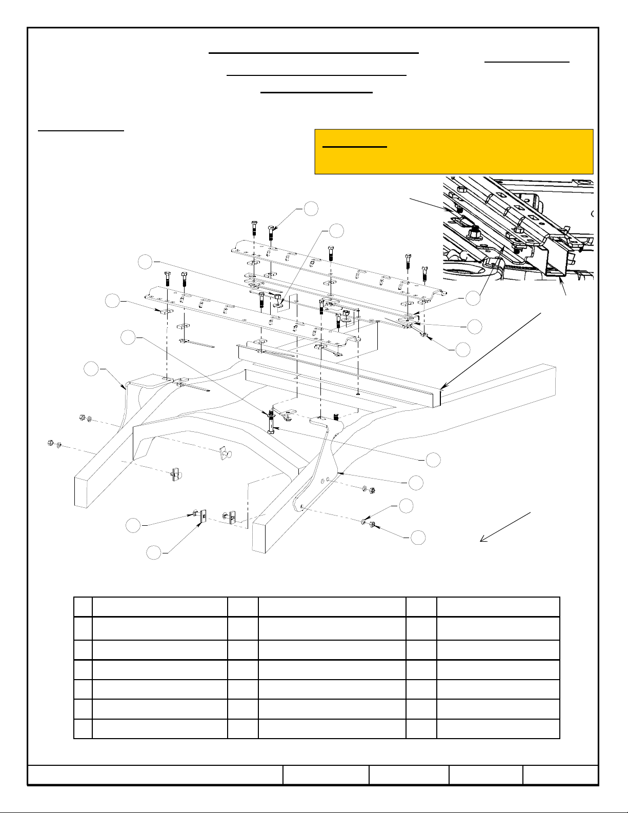
CUSTOM QUICK INSTALL
MOUNTING KIT
Dodge Ram 1500
(Does not fit 5-1/2’ beds)
WARNING: Under no circumstances do we recommend
exceeding the towing vehicle manufacturers recommended vehicle
towing capacity.
Relocate
Elect. Harness
5
15
Here
Part Numbers:
50083
13
16
2
11
1
4
10
9
7
FIG. 1
3
Cross member
12
8
VEHICLE FORWARD
INSTALLATION SHOWN FOR THE 58058 OR 30035 RAILS
Bed
# Name # Name # Name
1 Bracket, Front Left 1 7 .25” x 1” x 2” Blocks 4 13 Spacer Plate* 10
2 Bracket, Front Right 1 8 ½” Nut Handles 10 14 5/8” Nut Grade 2* 2
3 C-Channel 1 9 ½” Hex head Nuts 4 15 5/8”Serated Washer* 2
4 ½” Lock washers 4 10 ½” x 1.75” Carriage Bolts 4 16 5/8” Flat Washer* 2
5 ½” x 2” Bolts Grade 5 10 11 5/8” x 3.5” Bolts Grade 5 2
6 Wire Pulls 2 12 .25” x 1” x 3” Blocks 5
Fasteners shown with (*) are supplied with rail kit 58058
© 2011, 2013, 2014 Cequent Performance Products
Printed in Mexico
Sheet 1 of 6 50083N 2/18/2014 Rev. E
Page 3

DO NOT INSTALL THIS PRODUCT ON OR ATTEMPT TO TOW WITH A TRUCK WITH A BED THAT IS
FOR
INSTALLATION
OF 58058 OR 30035
Installation Instructions
CUSTOM QUICK INSTALL
MOUNTING KIT
Part Numbers:
50083
Dodge Ram 1500
RAIL KITS
1. Do not install mounting rails over plastic bed liners. Plastic bed liners must be cut out of the way to provide metal to metal
contact. Mounting rails may be installed on spray in liners.
2. Use only bolts, nuts, and washers supplied to install this kit. All bolts & nuts are Grade 5 unless otherwise specified.
3.
LESS THAN 6’ LONG.
4. These instructions are guidelines only, actual installation is the responsibility of the installer and the owner. Always measure
truck and trailer before installing hitch to be sure that there is clearance at the cab and at the bumper to allow for turns.
5. On the driver’s side frame rail, temporarily remove the forward hex nuts and ground wires attached to the vehicle frame.
6. Remove the spare tire if this helps to give more room to install the product.
7. Remove the plastic fender wells.
8. Place the rearward mounting rail in the bed of the vehicle. Center the rail from left to right on the floor of the truck bed and use
your tape measure to locate the proper distance from the rear of the rail to the rear edge of the truck box as illustrated on page 3.
9. Use a center punch to mark the holes in the rail per the illustration. Move the rail out of the way and drill each position through
the bed with a 1/8” drill bit. Note: On the driver’s side of the vehicle the gas tank is located below the bed of the vehicle.
When drilling holes through the bed be sure not to damage the fuel tank.
(Does not fit 5-1/2’ beds)
10. For Dual Exhaust, unbolt driver’s side exhaust hanger from cross-member and remove. If no Dual Exhaust, go to next step.
11. To place the c-channel above the cross member as shown on page 1, temporarily remove the plastic clips that hold the wiring
harness to the top of the cross member. Disconnect electrical connectors from both end of this harness section and move it out of
the way. Also remove the rear differential breather tube from the cross member and shock mount. Place c-channel approximately
centered from left to right. Check that the 1/8” drilled holes align with the slots in the c-channel.
12. Enlarge the 1/8” drilled holes to 9/16” with a drill. Paint bare metal as required.
13. Fasten the c-channel to the vehicle frame as shown in Figure 1 using 5/8” hardware. Bolt up through the trucks cross member.
14. Reposition the rear mounting rail over the holes in the bed and fasten the mounting rail to the c-channel using the supplied ½” hex
bolts (as shown in figure 1). Use the supplied U-shaped blocks between the c-channel or mounting rails and the truck bed to
ensure metal to metal contact.
15. For Dual Exhaust, reattach exhaust hanger that was removed in step 10.
16. Place the unassembled 5thwheel support arches/slider/goose into the already installed mounting rail. Position the forward
mounting rail with the support arches/slider/goose by inserting the tabs into the mounting rail and pushing the mounting rail tight
towards the other mounting rail. Ensure that the mounting rail is centered on the bed of the vehicle. This will position the rail in
the correct location and ensure that the 5thwheel will have a snug fit to the truck. Note: If more than one hitch product will be
used with the mounting rails then both types should be used at the same time to align the forward mounting rail. This will ensure
that one product does not compromise the fit of the other.
17. Use a center punch to mark the holes in the forward rail per the illustration on page 3. Move the rail out of the way and drill each
position with a 1/8” drill bit. Enlarge the 1/8” drilled holes to 9/16” and paint bare metal as required. Reposition the mounting
rails over the holes drilled in the bed.
18. Install the front frame rail brackets as shown in figure 1, use supplied U-shaped blocks. The brackets install ahead of the hat
section that supports the bed. Use the ½” pull wire to pull the carriage bolts and square hole plates into the frame.
19. Starting with the hex bolts that fasten the rails to the frame brackets thru the bed, torque all the nuts. Torque the hex bolts
positioned in the center of the rails. Torque the fasteners that attach the frame brackets to the vehicle frame then all remaining
fasteners.
20. Re-install the ground wire remove in installation step 5. Re-install spare tire. Re-attach the wiring harness and the differential
breather tube that were removed in step 10. Torque the 1/2” fasteners to 75 (ft-lb.) 102 (N*M) Torque the 5/8” fasteners to 150
(ft-lb.) 204 (N*M).
© 2011, 2013, 2014 Cequent Performance Products
Printed in Mexico
Sheet 2 of 6 50083N 2/18/2014 Rev. E
Page 4

Installation Instructions
CUSTOM QUICK INSTALL
MOUNTING KIT
Dodge Ram 1500
(Does not fit 5-1/2’ beds)
Position the Rail
RAILS 58058 OR 30035 ONLY
USE SADDLE/SLIDER/ARCHES TO
LOCATE FRONT RAIL
30-15/16”
28-15/16”
Part Numbers:
50083
2-3/4”
FOR RAILS 58058 OR 30035 ONLY
© 2011, 2013, 2014 Cequent Performance Products
Printed in Mexico
Sheet 3 of 6 50083N 2/18/2014 Rev. E
Page 5

11
12
6
14
13
2
8
1
12
9
10
7
4
3
8
5
VEHICLE FORWARD
FIG. 2
INSTALLATION SHOWN FOR THE 30124 OR 30095 RAILS
# Name # Name # Name
1 Bracket, Front Left 1 7 .25” x 1” x 2” Blocks 4 13 5/16” x 1.5” x 5” Blocks* 2
2 Bracket, Front Right 1 8 5/8” Serrated Washers 6 14 5/8” x 1.27 Tube Spacers* 2
3 C-Channel 1 9 ½” Hex head Nuts 4 15
4 ½” Lock washers 4 10 ½” x 1.75” Carriage Bolts 4 16
5 5/8” Nut Grade 2 6 11 5/8” x 3.5” Bolts Grade 5 6 17
6 7/8” x 1 ¾” Tube Spacers 2 12 5/8” Flat Washers 6 18
Fasteners shown with (*) are supplied with rail kit 30124
© 2011, 2013, 2014 Cequent Performance Products
Printed in Mexico
Sheet 4 of 6 50083N 2/18/2014 Rev. E
Page 6

FOR
INSTALLATION OF
30124 OR 30095
Installation Instructions
CUSTOM QUICK INSTALL
MOUNTING KIT
RAIL KITS
1. Do not install mounting rails over plastic bed liners. Plastic bed liners must be cut out of the way to provide metal to metal contact.
Mounting rails may be installed on spray in liners.
2. Use only bolts, nuts, and washers supplied to install this kit. All bolts are grade 5 and nuts are grade 5 unless otherwise specified.
3. DO NOT INSTALL THIS PRODUCT ON OR ATTEMPT TO TOW WITH A TRUCK WITH A BED THAT IS
LESS THAN 6’ LONG.
4. These instructions are guidelines only, actual installation is the responsibility of the installer and the owner. Always measure truck
and trailer before installing hitch to be sure that there is clearance at the cab and at the bumper to allow for turns.
5. On the driver’s side frame rail, temporarily remove the forward hex nuts and ground wires attached to the vehicle frame.
6. Remove the spare tire if this helps to give more room to install the product.
7. Remove the plastic fender wells.
8. Place the rearward mounting rail in the bed of the vehicle. Center the rail from left to right on the floor of the truck bed and use
your tape measure to locate the proper distance from the rear of the rail to the rear edge of the truck box as illustrated on page 6.
9. Use a center punch to mark the holes in the rail as shown in illustration on page 6. Move the rail out of the way and drill each
position through the bed with a 1/8” drill bit. Note: On the driver’s side of the vehicle the gas tank is located below the bed of
the vehicle. When drilling holes through the bed be sure not to damage the fuel tank.
Dodge Ram 1500
(Does not fit 5-1/2’ beds)
Part Numbers:
50083
10. For Dual Exhaust, remove driver’s side exhaust hanger from cross-member. If no Dual Exhaust, go to next step.
11. To place the c-channel above the cross member as shown on page 4. Temporarily remove the plastic clips that hold the wiring
harness to the top of the cross member. Also remove the rear differential breather tube from the cross member. Place c-channel
approximately centered from left to right. Check that the 1/8” drilled holes align with the slots in the c-channel.
12. Enlarge the 1/8” drilled holes to 1-1/8” with a hole saw.
13. Fasten the c-channel to the vehicle frame as shown in Figure 2 using 5/8” hardware. Bolt up through the trucks cross member.
Install the 1-3/4” long tube spacers above the channel and within truck bed.
14. Reposition the mounting rail over the tube spacer installed in step 13, and fasten the mounting rail to the c-channel using the
supplied 5/8” hex bolts. Note: Be sure 1-3/4” long tube spacers are installed between the c-channel and mounting rails to ensure
metal to metal contact.
15. For Dual exhaust, reattach exhaust hanger that was removed in step 10.
16. Place the unassembled 5thwheel support arches/slider/goose into the already installed mounting rail. Position the forward mounting
rail with the support arches/slider/goose by inserting the tabs into the mounting rail and pushing the mounting rail tight towards the
other mounting rail. Ensure that the mounting rail is centered on the bed of the vehicle. This will position the rail in the correct
location and ensure that the 5thwheel will have a snug fit to the truck. Note: If more than one hitch product will be used with the
mounting rails then both types should be used at the same time to align the rearward mounting rail. This will ensure that one product
does not compromise the fit of the other.
17. Use a center punch to mark the holes in the forward rail per the illustration. Move the rail out of the way and drill each position
with a 1/8” drill bit.
18. Install the front frame rail brackets as shown on page 4. Use the ½” pull wire to pull the carriage bolts and square hole plates into
the frame. Enlarge 1/8” drilled holes to 5/8” with a drill bit. Install the 1.27” tube spacer in hole just drilled. If the hole drilled in
your bed falls on the rise of your corrugation, place 5” x 1” block (part #13) underneath bed. If the hole falls in the dip of your
corrugation, place block on top of bed. Reposition the mounting rails over the holes drilled in the bed. Fasten the front rail to the
frame brackets as shown in figure 2 using the 5/8” bolt and flat washer down through the rail and tube spacer. Fasten with 5/8”
serrated washer and nut.
19. Starting with the hex bolts that fasten the rails to the frame brackets, torque all the nuts. Torque the fasteners that attach the frame
brackets to the vehicle frame. Torque the 5/8” fasteners to 150 (ft-lb.) 204 (N*M) Torque the 1/2” fasteners to 75 (ft-lb.) 102
(N*M)
20. Re-install the ground wires remove in installation step 5. Re-install spare tire. Re-install spare tire. Re-attach the wiring harness and
the differential breather tube that were removed in step 10.
© 2011, 2013, 2014 Cequent Performance Products
Printed in Mexico
Sheet 5 of 6 50083N 2/18/2014 Rev. E
Page 7

Installation Instructions
CUSTOM QUICK INSTALL
RAILS 30095 OR 30124 ONLY
USE SADDLE/SLIDER/ARCHES TO
LOCATE FRONT RAIL
30124
33”
31”
Part Numbers:
50083
MOUNTING KIT
Dodge Ram 1500
(Does not fit 5-1/2’ beds)
Position the Rail
. .
Bolt
. .
4-7/8”
FOR RAILS 30124 OR 30095 ONLY
© 2011, 2013, 2014 Cequent Performance Products
Printed in Mexico
Sheet 6 of 6 50083N 2/18/2014 Rev. E
 Loading...