

Page 1
InstallationInstructions
4 Bolt System: Instructions for 30124 or 30095 on pages 5
7. Fasteners that are not identify are supplied with rail kit 30124.
2011 & UP sh
CUSTOM QUICK INSTALL MOUNTI NG KIT
2011 & UP Ford Super Duty F-250/F-350/F-450
Part Number:
50073
WARNING: Under no circumstances do we recommend exceeding the towing vehicle manufacturers recommended vehicle towing
capacity.
2011 & UP
READ ALL INSTRUCTIONS BEFORE STARTING THE INSTALLATION
Custom Quick Install mounting brackets only include the hardware to attach the custom brackets to the frame..
10 Bolt System: Instructions for 58058 or 30035 on pages 1-4. Fasteners that are not identify are supplied with rail kit 58058.**
-
Equipment Required:
***
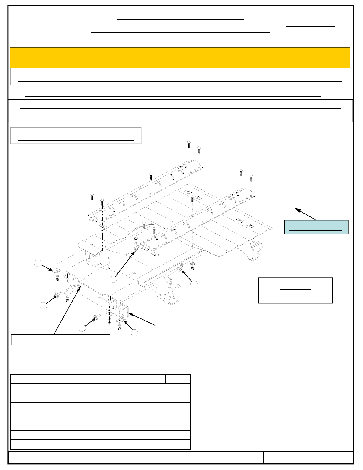
10 BOLT INSTALLATION
Fastener Kit: 50073F
Wrenches: 3/4, 7/8, 15/16, 15 mm, 18mm
All Fasteners
Typical Both Sides
Drill Bits: 1/8”, 9/16”
Other Tools: Center Punch, Measuring Tape
1
3
2
2
USE THIS HOLE ON PASSENGERS SIDE
Fasteners listed below are supplied with this kit, all other mentioned
fasteners are supplied with part number 30035, 58058, 30095 or 30124.
Item
Description Quantity
1SPACER1/4"x11/2"x2" 8
2BOLTANDWASHERM14X45 4
3NUTANDRETAINERM14 4
4WASHERFLAT1/4"(Se e FI G.1c) 2
5NUT,NYLOK1/4"‐20(See FIG.1c) 1
6BOLT,HEXHEAD 1/4"‐ 20x11/4"GRADE2(Se e FIG.1c) 1
7L‐BRACKET(See FI G.1c) 1
1
Driver’s side frame bracket
Vehicle Forward
3
Figure 1
own
z 2010 Cequent Performance Products, Inc.
Sheet 1 of 7 50073N 12/10/10 Rev. A
Page 2
InstallationInstructions
way to provide metal to metal contact
Mounting rails may be installed on spray in liners
f
il
flange nut
keep for later use
See Figure 1b
Rotate the tubes up and out of the wa
Install the L
bracket (7) with 1/4” hardware
9.Install the 1/2 x 2 long carriage bolts with the U
-
shaped spacer to be located in the corrugation between the box and the rail
s
Part Numbers:
CUSTOM QUICK INSTALL MOUNTI NG KIT
2011 & UP Ford Super Duty F-250 / F-350 / F-450
¾ Do not install mounting rails over plastic bed liners. Plastic bed liners must be cut out of the
.
¾ Use only bolts, nuts, and washers supplied to install this kit. All bolts and nuts are Grade 5
unless otherwise specified.
¾ These instructions are guidelines only, actual installation is the responsibility of the installer
and the owner. Always measure truck and trailer before installing hitch to be sure that there is
clearance at the cab and at the bumper to allow for turns.
50073
.
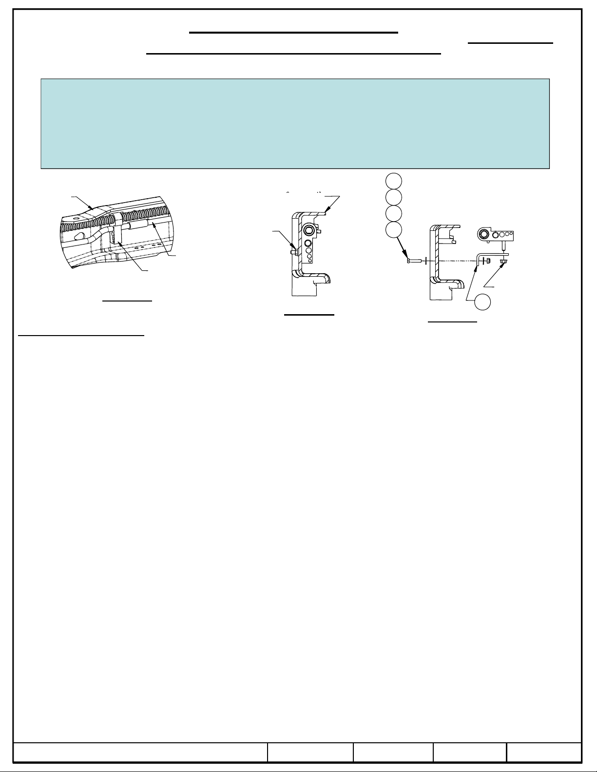
Driver’s side
frame rail
Tube
holder
Figure 1a
Inside of frame rail
Driver’s side
rame ra
Existing
flange nut
Vapor
tube
Figure 1b
5
4
4
6
Existing
7
Figure 1c
Installation Instructions
1. Lower and remove spare tire if extra room is needed.
2. On 2011 and up Gas Engine Vehicles Only. The vapor tube running along the inside of the driver’s side frame rail must be
relocated prior to installing the driver’s side bracket. See Figure 1a. Remove the flange nut from the outside of the fram e and
.
(4)(5)(6), as shown in Figure 1c. Tighten the L-bracket (7) to the frame, but leave the tube holder loose to aid bracket
installation.
3. Place the front mounting rail in the box of the truck. Using your tape measure, center the rail between the weld seams on the
length of the truck box floor and the proper distance from the rear edge of the truck box as illustrated in Figure 6. See page 1for
mounting the brackets to the rails and brackets to the frame.
4. Mark and center punch the holes as per the illustration in Figure 6. Move the rail out of the way and drill each position wi th a
1/8”drill bit. Warning: When drilling holes be aware of potential risks to vehicle components, such as brake lines and fuel
tanks, and make appropriate safe guards to protect them from damage.
5. Temporarily position the frame brackets on the outside of the frame and check that the 1/8” drilled holes align with the slots of
the frame bracket. Remove the frame bracket from the vehicle.
6. Enlarge the 1/8”drilled holes to 9/16” with the step drill. Warning: When drilling holes be aware of potential risks, such as
brake lines and fuel tanks, to vehicle components and make appropriate safe guards to protect them from damage.
7. Loosely install the frame brackets by aligning the brackets with holes in the frame. Insert M14 bolt and washer(2) into slots in
the bracket and through the holes in the frame. Install the M14 nut w ith retainer(3) on the bolt. Snug the bolts. Do not tighten.
8. Reposition the mounting rail over the holes.
”
”
Note: The U-shaped spacer will have to be installed before inserting the 1/2" carriage bolts through the mounting rail and box
floor. This insures a metal to me tal contact. A U-shaped spacer is not needed for the attachment at the center of the rail. Attach
the carriage bolts on the ends of the rails with spacers(1), lock washers, and nuts as per the Figure 1 and tighten snug to keepthe
mounting rail from moving. Attach the carriage bolt in the middle with a conical washer and nut.
.
y.
-
.
z 2010 Cequent Performance Products, Inc.
Sheet 2 of 7 50073N 12/10/10 Rev. A
Page 3

10. Place the unassembled fifth wheel saddles/slider/goose into the already installed mounting rail. Position the second mountin grail
with the saddles/slider/goose by inserting the tabs into the mounting rail and pushing the mounting rail tight towards the other
mounting rail. Ensure that the mounting rail is centered between the weld seams on the length of the truck box floor. This will
position the mounting rail in the correct location and ensure that the fifth wheel will have a snug fit to the truck. NOTE: If more
than one hitch product will be used with the rails then both should be used at the same time to align the second rail. This will
ensure that one product does not compromise the fit of the other.
11. Repeat steps 5 thru 10 for the other side of the vehicle.
12. Tighten the fasteners in the following sequence: 1) torque the mounting rails to the frame brackets, 2) torque the frame brackets
to the truck frame.
Torque all 1/2" Grade 5 hardware to 72 ft-lbs (98 N-m), M14 - 10.9 hardware to 148
ft-lbs (201 N-m).
13. On 2011 and up Gas Engine Vehicles Only. Use the factory flange nut that was removed in Step 2 to tighten the tube holder
onto the L-bracket as shown in Figure 1c.
14. Reinstall spare tire if it was removed.
z 2010 Cequent Performance Products, Inc.
Sheet 3 of 7 50073N 12/10/10 Rev. A
Page 4

Figure 6
z 2010 Cequent Performance Products, Inc.
Sheet 4 of 7 50073N 12/10/10 Rev. A
Page 5

INSTRUCTIONS WHEN USING THE 30124 RAIL KIT
way to provide metal to metal contact
Mounting rails may be installed on spray in liners
4 BOLT INSTALLATION
FRONT OF
WITH THE 2011 & UP FORD SUPER DUTY F-250, F-350, F-450
HARDWARE AND INSTALLATION IS THE SAME FOR BOTH THE DRIVERS SIDE AND PASSENGERS SIDE
¾ Do not install mounting rails over plastic bed liners. Plastic bed liners must be cut out of the
.
¾ Use only bolts, nuts, and washers supplied to install this kit. All bolts are Grade 5 and nuts are
Grade 5 unless otherwise specified.
¾ These instructions are guidelines only, actual installation is the responsibility of the installer
and the owner. Always measure truck and trailer before installing hitch to be sure that there is
clearance at the cab and at the bumper to allow for turns.
Equipment Required:
Fastener Kit: 50073F
Wrenches: 3/4, 7/8, 15/16, 15 mm
Drill Bits: 1/8”, 11/16”
Other Tools: Center Punch, Measuring Tape
Figure 7
5/8” CARRIAGE
Hardware and
installation shown
is the same for the
passengers side.
BOLT
1-1/4” TUBE
SPACER
5/16” SPACER
.
RAIL
TRUCK
Driver’s side
frame rail
Figure 7A
Inside of frame rail
5/8” CONICAL
WASHER
5/8” NUT
Vapor
tube
Tube
holder
Existing
flange nut
Driver’s side
frame rail
Figure 7B
FRAME BRACKET
HARDWARE ITEMS LISTED
6
4
4
5
ARE FROM PAGE 1 CHART
Existing
flange nut
L-bracket
Figure 7C
z 2010 Cequent Performance Products, Inc.
Sheet 5 of 7 50073N 12/10/10 Rev. A
Page 6

4 BOLT INSTALLATION
4.Mark
illustrati
ill
iti
i
th
tighten
13.Place the unassembled fifth wheel saddles/slider/goose into the already installed mounting rail. Position the second mounting
Installation Instructions
1. Lower and remove spare tire if extra room is needed.
2. On 2011 and up Gas Engine Vehicles Only. The vapor tube running along the inside of the driver’s side frame rail must be
relocated prior to installing the driver’s side bracket. See Figure 7a on the previous page. Remove the flange nut from the
outside of the frame and keep for later use. See Figure 7b. Rotate the tubes up and out of the way. Install the L-bracket (7)
with 1/4” hardware(4)(5)(6), as shown in Figure 7c. Tighten the L-bracket (7) to the frame, but leave the tube holder loose to
aid bracket installation.
3. Place the front mounting rail in the box of the truck. Using your tape measure, center the rail between the weld seams on the
length of the truck box floor and the proper distance from the rear edge of the truck box as illustrated in Figure 8. See page 1
for mounting the brackets to the rails and brackets to the frame.
and center punch the holes as per the
1/8”drill bit. Warning: When drilling holes be aware of potential risks to vehicle components, such as brake lines and
fuel tanks, and make appropriate safe guards to protect them from damage.
5. Temporarily position the frame brackets on the outside of the frame and check that the 1/8” drilled holes align with the slots of
the frame bracket. Remove the frame bracket from the vehicle.
6. Enlarge the 1/8”drilled holes to 11/16” with the step drill. Warning: When drilling holes be aware of potential risks, such
as brake lines and fuel tanks, to vehicle components and make appropriate safe guards to protect them from damage.
7. Loosely install the frame brackets by aligning the brackets with holes in the frame as shown on page 1. Snug the bolts. Do not
.
8. Reposition the mounting rail over the holes.
9. Place a 5/16” thick spacer between the bed and the rail if the drilled hole in the bed is in the bottom of the corrugation. If the
hole is in the top of the corrugation, place the spacer between the bottom of the bed and the bracket below the bed.
10. Place the 1-1/4” tube spacers under the rails.
11. Insert the 5/8” carriage bolts through the rails and holes in the bed as shown in figure 7.
12. Install 5/8 conical washers and 5/8” nuts on the bolts. Snug up the hardware.
on in Figure 8. Move the rail out of the way and dr
each pos
on w
a
rail with the saddles/slider/goose by inserting the tabs into the mounting rail and pushing the mounting rail tight towards the
other mounting rail. Ensure that the mounting rail is centered between the weld seams on the length of the truck box floor. This
will position the mounting rail in the correct location and ensure that the fifth wheel will have a snug fit to the truck. NOTE: If
more than one hitch product will be used with the rails then both should be used at the same time to align the second rail. This
will ensure that one product does not compromise the fit of the other.
14. Repeat steps 5 thru 12 for the other side of the vehicle.
15. Tighten the fasteners in the following sequence: 1) torque the m ounting rails to the frame brackets, 2) torque the frame
brackets to the truck frame. M14 - 10.9 hardware to 148 ft-lbs (201 N-m), 5/8” Grade 5 hardware to 150 ft-lbs (204 N-m).
16. On 2011 and up Gas Engine Vehicles Only. Use the factory flange nut that was removed in Step 2 to tighten the tube holder
onto the L-bracket as shown in Figure 1c.
17. Reinstall spare tire if it was removed.
z 2010 Cequent Performance Products, Inc.
Sheet 6 of 7 50073N 12/10/10 Rev. A
Page 7

Figure 8
z 2010 Cequent Performance Products, Inc.
Sheet 7 of 7 50073N 12/10/10 Rev. A
 Loading...