

Page 1
Applications:
Years Make Models
2016 -
Current* Toyota Prius
Ratchet
Torque
Wrench
Safety
Glasses
Sockets
12 mm
DO NOT EXCEED LOWER OF TOWING VEHICLE
MANUFACTURER’S RATING OR:
Hitch Type Max Gross Trailer Weight Max Tongue Weight
Weight Carrying 2000 lb. (908 kg) 200 lb. (90.8 kg)
Weight Distributing X X
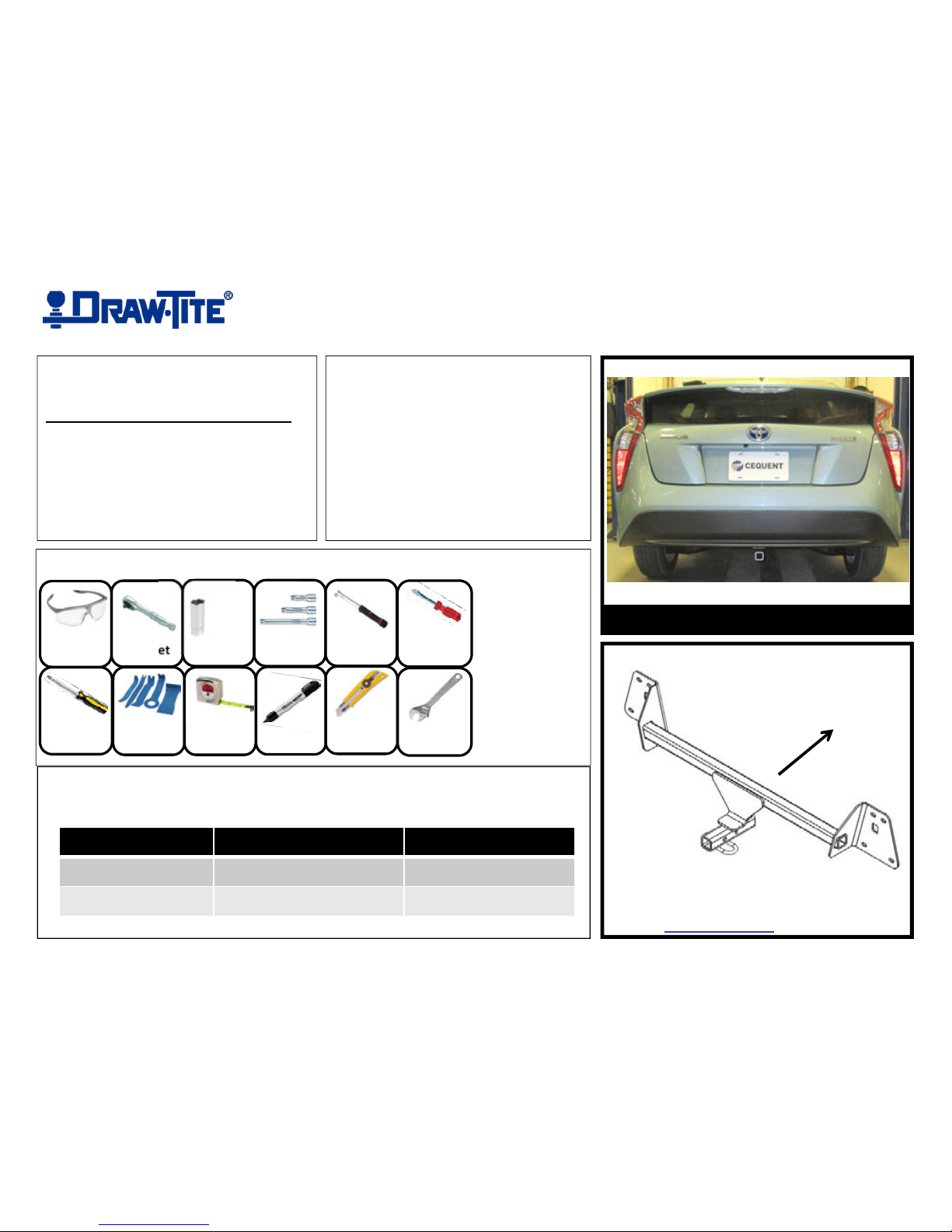
Representative Vehicle Photo
Installation Time: 45 min
The time listed above is the average time
for pr
ofessional installers. If you do not
feel comfortable performing this
installation on your own or are in need of
assistance, please contact a professional
installer.
Trailer Hitch Illustration
Front of
Vehicle
3’’ Socket
Exten
sion
Installation Instructions
PART NUMBERS: 24944, 77331, CQT24944
Equipment Required:
Phillips
Screwd
river
Tape
Measure
Flat
Head Screw
Driver
Plastic
Trim Tools
Utility
Knife
Marker
Adjustable
Wrench
Page 2

Note: check hitch frequently, making sure all fasteners and ball are properly tightened. If hitch is removed, plug all holes in trunk pan or other body panels to prevent entry of water and exhaust fumes. A hitch or ball which
has been damaged should be removed and replaced. Observe safety precautions when working beneath a vehicle and wear eye protection. Do not cut access or attachment holes with a torch. This product complies with safety
specifications and requirements for connecting devices and towing systems of the state of New York, V.E.S.C. Regulation V-5 and SAE J684.
Installation Instructions
PART NUMBERS: 24944, 77331, CQT24944
Proper torque is needed to keep the hitch secure to the vehicle when towing.
Always wear SAFETY GLASSES
when installing hitch
Rear
Figure 1
(Sold separately)
Drawbar Kit: 3593
Drawbar must be
used in the RISE
position only
2-7/8”
4-1/2”
Center Underbody Panel
Figure 5
Figure 2
Figure 4
Bumper end
panel
Bumper beam
Existing
M8-1.25 Bolts
(8) Places
Lower Fascia
Figure 3
1. Remove (3) plastic underbody panels – using a flat head screw driver, remove (14) plastic push-type rivets and (3) threaded panel fasteners from bottom panels.
2a. Lower Fascia removal - using a Phillips head screw driver, remove (2) screws located at bottom inside edge of lower fascia, (1) per side.
b.) using a plastic trim panel tool, remove (5) clips holding wiring harness to fascia retaining tabs. See Figure 2.
c.) using a plastic trim panel tool, gently remove the plastic fascia starting at the outer edges. See Figure 3.
3. Remove bumper beam – using a 12mm socket, remove (8) M8 bolts, (4) per side, attaching bumper beam to end panel. See Figure 1.
4. Bumper beam modification – using an adjustable wrench, bend the tabs on back of bumper beam up approximately 15 degrees. See Figure 4.
5. Hitch installation – raise hitch and bumper beam into position aligning holes with weldnuts in the end panel. Sandwich the hitch between bumper beam and end panel. See Figure 1.
6. Reinstall fasteners - Loosely reinstall the existing (8) M8 bolts into weldnuts in end panel, (4) per side.
7. Tighten all fasteners with torque wrench to 20 Lb.-Ft. (27 N*M)
8. Reinstall lower fascia and wiring clips – reinstall the lower fascia aligning tabs in lower fascia with upper fascia. Reinstall the (5) wiring clips into fascia tabs above the bumper beam.
Reinstall the (2) screws at outer edge of fascia.
9. Trim center underbody panel – measure, mark, and trim the center underbody panel. See Figure 5.
10. Reinstall underbody panels – reinstall the (3) underbody panels using the (14) push-type rivets and the (3) threaded panel fasteners.
Page 3

1. Remove (3) plastic underbody panels – using a flat head screw
driver, remove (14) plastic push-type rivets and (3) threaded panel
fasteners from bottom panels.
2b. Lower Fascia removal - using a plastic trim panel tool, remove (5)
clips holding wiring harness to fascia retaining tabs.
2a. Lower Fascia removal - using a Phillips head screw driver,
remove (2) screws located at bottom outer edge of lower fascia, (1) per
side.
2c. Lower Fascia removal - using a plastic trim panel tool, gently
remove the plastic fascia starting at the outer edges.
Page 4

3. Remove bumper beam – using a 12mm socket, remove (8) M8
bolts, (4) per side, attaching bumper beam to end panel.
5. Hitch installation – raise hitch and bumper beam into position
aligning holes with weldnuts in the end panel. Sandwich the hitch
between bumper beam and end panel.
4. Bumper beam modification – using an adjustable wrench, bend
the tabs on back of bumper beam up approximately 15 degrees.
6. Reinstall fasteners - Loosely reinstall the existing (8) M8 bolts into
weldnuts in end panel, (4) per side.
7. Tighten all fasteners with torque wrench to 20 Lb.-Ft. (27 N*M)
Proper torque is needed to keep the hitch secure to the vehicle when
towing.
Page 5

8. Reinstall lower fascia and wiring clips – reinstall the lower fascia
aligning tabs in lower fascia with upper fascia. Reinstall the (5) wiring
clips into fascia tabs above the bumper beam.
9. Trim center underbody panel – measure, mark, and trim the center
underbody panel.
8. Continued:
Reinstall the (2) screws at outer edge of fascia.
10. Reinstall underbody panels – reinstall the (3) underbody panels
using the (14) push-type rivets and the (3) threaded panel fasteners.
2-7/8”
4-1/2”
 Loading...