

Page 1

INSTRUCTIONS FOR
Combined Stud Detector
& Distance Estimator
Stock No.88988 Part No.DMSD
IMPORTANT: PLEASE READ THESE INSTRUCTIONS CAREFULLY TO ENSURE THE SAFE AND
GENERAL INFORMATION
Read all these instructions before operating this product and save these instructions.
This manual has been compiled by Draper Tools and is an integrated part of the product with which it is enclosed and
should be kept with it for future references.
This manual describes the purpose for which the product has been designed and contains all the necessary information
to ensure its correct and safe use. We recommend that this manual is read before any operation or, before performing
any kind of adjustment to the product and prior to any maintenance tasks. By following all the general safety instructions
contained in this manual, it will ensure both product and operator safety, together with longer life of the product itself.
All photographs and drawings in this manual are supplied by Draper Tools to help illustrate the operation of the product.
Whilst every effort has been made to ensure accuracy of information contained in this manual, the Draper Tools policy of
continuous improvement determines the right to make modifications without prior warning.
EFFECTIVE USE OF THIS PRODUCT.
Page 2

CONTENTS
Contents/Declaration .................................................................................................................................. 1
Specification/Assembly ................................................................................................................................ 2
Operation and Use ................................................................................................................................... 3-4
Disposal ...................................................................................................................................................... 5
Explanation of Symbols/Pictograms ............................................................................................................. 5
DECLARATION OF CONFORMITY
We:
Draper Tools Ltd.,
Hursley Road,
Chandler’s Ford,
Eastleigh, Hampshire.
SO53 1YF.
England.
Declare under our sole responsibility that the product:
Stock No:- 88988.
Part No:- DMSD.
Description:- Distance Measure Stud Detector.
To which this declaration relates is in conformity with the following directive(s)
89/336/EEC
With reference to
EN61326:1997+A1+A2
J.N. Draper
Chairman 05/07/2005
- 1 -
Page 3
SPECIFICATION
The Draper Tools policy of continuous improvement determines the right to change
specification without notice.
Stock No. ......................................................................................................................... 88988
Part No. ............................................................................................................................ DMSD
Detection Distance:
Stud ..................................................................................................................... 19.05mm
Distance ......................................................................................................... 0.60-15.24M
Accuracy ............................................................................................................. ±0.5% ±1 Digit
Resolution .................................................................................................................. 0.01M (1")
Aperture Angle (approx.) ......................................................................................................... 5°
Laser Diode Type ................................................................................................... 650nM Diode
Laser Class ..................................................................................................................... Class 2A
Power Source* .............................................................................................................. 9V (PP3)
Weight .......................................................................................................................... 0.192kg
Operating Temperature ........................................................................... 32°F-104°F (0°C-40°C)
* Draper Stock No.62044
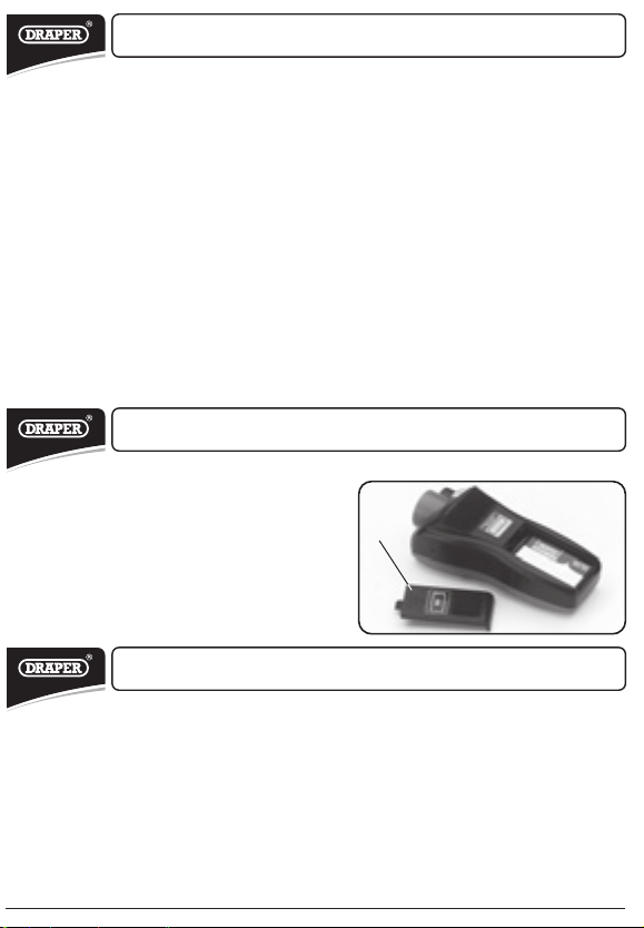
ASSEMBLY
- BATTERY INSTALLATION: (FIG.1)
When the battery power starts getting low a
battery symbol will appear on the display.
Slide out battery door $ located at the rear
of the unit. Connect a new 9V PP3 battery*
(not supplied) into the battery compartment
and ensure the correct polarity. Replace cover
$ and securely clip in place.
* Draper Stock No.62044
FIG.1
$
CARE AND HANDLING
1. DO NOT shine or aim the laser pointer at people or animals, as it may cause damage to
eyesight.
2. The combined stud/distance detector is a precision instrument which must be handled with
care.
3. Avoid shock, vibrations and extreme heat.
4. Avoid dust and water, which may obstruct the lens. If needed, use a soft cloth to clean the lens.
5. Keep the laser tool dry and clean.
6. Check battery regularly to avoid deterioration.
7. Remove battery if the laser tool is to be stored for an extended period of time.
- 2 -
Page 4

OPERATION AND USE
- STUD DETECTOR: (FIG.2)
Place the detector flat against the wall. Press
and hold button % to calibrate the unit. The
buzzer will sound to confirm and the display
will read 'Stud'.
NOTE: If by chance, the calibration is carried out
too close or over a stud the detector will never
pick up any readings, and give false
information. For this reason it is advisable to
take a couple of readings and calibrate the unit
in different positions to ensure accuracy.
Upon detection of a stud or nogging the bars
will begin to increase in the LCD display and the
buzzer will sound when all twelve bars are lit.
The best method of accuracy is to mark the wall
at the point where the buzzer has sounded.
Then move the detector approximately 30cm
past this point. Trace back with the detector
again, until the buzzer is sounded. Mark the
wall, and the midway point between the marks
is the centre of the stud/nogging.
NOTE: The wall must be a cavity design for the
detector to work correctly. If the cavity has
been filled with glass fibre, even this may effect
the readout.
- DISTANCE DETECTION: (FIG.3)
Ensure the detector is positioned and pointing
perpendicular to the target area. The laser is a
guide to where the measurement is being
taken.
The target area must be a rigid surface without
any irregularities. The target cannot be
impaired by obstacles.
For more accurate results and when measuring
longer distances ensure the target area is large
(measurements over 12M the target should be
2
>3M
). For small and irregular surfaces try
affixing a piece of board as the target area.
The ultrasonic distance detection will not
measure through glass, but WILL measure to
glass.
Measure from base (i.e. measurement includes
length of detector).
Press button & to select metric or imperial
results.
FIG.2
%
FIG.3
)
*
&
'
,
+
(
- 3 -
Page 5

OPERATION AND USE
1. TO TAKE STANDARD MEASUREMENTS:
Press button ' to take the measurement. The result will be displayed unless an error has
occurred in which case try again.
2. TO ADD RESULTS: (without using the memory)
Press button ' to take the measurement. Press button ( to enter the addition mode.
The '+' is displayed on the LCD. Press button ' again to take the next reading. Press
button ( to display the result.
3. TO ADD RESULTS: (using the memory)
Press button ' to take the measurement. Press button ) to save the current
measurement. Press button ' to to take the next reading. Press button ( to enter the
addition mode. The '+' is displayed on the LCD. Press button * to recall the previous
measurement. Press button ( to display the result.
4. TO TAKE AREA MEASUREMENTS:
Press button + to enter area mode. The symbol will appear on the LCD with the 'L'
flashing. Press button ' to take the length measurement. If the measurement was
successful the 'W' will begin flashing. Press button ' to take the width measurement. If
successful the result in Ft
' to cycle through the two individual measurements or press button + to begin a new
area measurement. Alternatively, press and hold button ' for two seconds to exit the
area mode.
NOTE: It is possible to store an area result in the memory, take a fresh area measurement
and add them together using button (.
5. TO TAKE VOLUME MEASUREMENTS:
Press button , to enter volume mode. The symbol will appear on the LCD with the 'L'
flashing. Press button ' to take the length measurement. If the measurement was
successful the 'W' will begin flashing. Press button ' to take the width measurement. If
successful the 'H' will begin flashing. Press button ' to take the height measurement. If
successful the result in Ft
button ' to cycle through the three individual measurements or press button , to
begin a new volume measurement. Alternatively, press and hold button ' for two
seconds to exit the area mode.
NOTE: All length, width and height measurements must be complete to exit the volume
mode.
NOTE: It is possible to store a volume result in the memory, take a fresh volume
measurement and add them together using button (.
2/M2
will be displayed under the individual measurement button
3/M3
will be displayed under the individual measurement. Press
- 4 -
Page 6

DISPOSAL OF POWER TOOLS
- At the end of the machine‘s working life, or when it can no longer be repaired, ensure that
it is disposed of according to national regulations.
- Contact your local authority for details of collection schemes in your area.
In all circumstances:
• Do not dispose of power tools with domestic waste.
• Do not incinerate.
• Do not abandon in the environment.
• Do not dispose of WEEE* as unsorted municipal waste.
* Waste Electrical & Electronic Equipment.
EXPLANATION OF SYMBOLS/PICTOGRAMS
Do not dispose of WEEE*
as unsorted municipal waste.
* Waste Electrical & Electronic Equipment.
- 5 -
Page 7

NOTES
- 6 -
Page 8

CONTACTS
- DRAPER TOOLS LIMITED,
Hursley Road, Chandler's Ford,
Eastleigh, Hampshire. SO53 1YF. U.K.
- Helpline: (023) 8049 4344
- Sales Desk: (023) 8049 4333
- General Enquiries: (023) 8026 6355
- Service/Warranty Repair Agent
For aftersales servicing or warranty repairs, please
contact the Draper Tools Helpline for details of an
agent in your local area.
YOUR DRAPER STOCKIST
PJMC0316
drapertools.com
 Loading...