

Page 1

SUBMERSIBLE
WATER PUMP
98912.
These instructions accompanying the product are the original instructions. This document is part of the product,
keep it for the life of the product passing it on to any subsequent holder of the product. Read all these
instructions before assembling, operating or maintaining this product.
This manual has been compiled by Draper Tools describing the purpose for which the product has been
designed, and contains all the necessary information to ensure its correct and safe use. By following all the
general safety instructions contained in this manual, it will ensure both product and operator safety, together
with longer life of the product itself.
AlI photographs and drawings in this manual are supplied by Draper Tools to help illustrate the operation of the
product.
Whilst every effort has been made to ensure the accuracy of information contained in this manual, the Draper
Tools policy of continuous improvement determines the right to make modifications without prior warning.
Page 2

1. INTRODUCTION
1.1 INTRODUCTION:
USER MANUAL FOR: Submersible pump.
Stock No: 98912.
Part No: SWP120A.
1.2 REVISIONS:
Date first published March 2019.
As our user manuals are continually updated, users should make sure that they use
the very latest version.
Downloads are available from: http://drapertools.com/manuals
Draper Tools Limited
Hursley Road
Chandler’s Ford
Eastleigh
Hampshire
SO53 1YF
UK
Website: drapertools.com
Product Helpline: +44 (0) 23 8049 4344
General Fax: +44 (0) 23 8026 0784
1.3 UNDERSTANDING THIS MANUALS SAFETY CONTENT:
WARNING! – Information that draws attention to the risk of injury or death.
CAUTION! – Information that draws attention to the risk of damage to the product or
surroundings.
1.4 COPYRIGHT © NOTICE:
Copyright © Draper Tools Limited.
Permission is granted to reproduce this publication for personal and educational use
only. Commercial copying, redistribution, hiring or lending is prohibited.
No part of this publication may be stored in a retrieval system or transmitted in any
other form or means without written permission from Draper Tools Limited.
In all cases this copyright notice must remain intact.
- 2 -
Page 3

2. CONTENTS
1. TITLE PAGE
1.1 INTRODUCTION..........................................................................................................2
1.2 REVISION HISTORY ..................................................................................................2
1.3 UNDERSTANDING THIS MANUAL .............................................................................2
1.4 COPYRIGHT NOTICE..................................................................................................2
2. CONTENTS
2.1 CONTENTS ....................................................................................................................3
3. WARRANTY
3.1 WARRANTY.................................................................................................................4
4. INTRODUCTION
4.1 SCOPE.........................................................................................................................5
4.2 SPECIFICATION..........................................................................................................5
4.3 HANDLING AND STORAGE........................................................................................ 5
5. HEALTH AND SAFETY INFORMATION
5.1 GENERAL SAFETY INSTRUCTIONS FOR POWER TOOL USE ...............................6
– 1) Work area safety ................................................................................................ 6
– 2) Electrical safety..................................................................................................6
– 3) Personal safety...................................................................................................6
– 4) Power tool use and care .................................................................................... 7
– 5) Service ................................................................................................................ 7
5.2 ADDITIONAL SAFETY INSTRUCTIONS FOR SUBMERSIBLE WATER PUMPS ......8
5.3 CONNECTION TO THE POWER SUPPLY ................................................................. 9
6. TECHNICAL DESCRIPTION
6.1 IDENTIFICATION.......................................................................................................10
6.2 MAIN COMPONENT DESCRIPTIONS ......................................................................10
7. UNPACKING AND CHECKING
7.1 PACKAGING ............................................................................................................. 11
8. READYING THE PUMP
8.1 INSTALLATION OF PARTS .......................................................................................12
9. INSTALLING THE PUMP
9.1 PUMPING DISTANCE AND VOLUME ....................................................................... 13
9.2 FLOATING SWITCH...................................................................................................14
9.3 SET CT OFF FLOAT HEIGHT....................................................................................15
9.4 SET INTEGRAL FLOAT HEIGHT...............................................................................15
9.5 PLACEMENT ............................................................................................................. 16
9.6 CONNECTING TO POWER VIA RCD .......................................................................17
9.7 SWITCHING ON THE PUMP.....................................................................................17
10. MAINTENANCE
10.1 CLEARING OBSTRUCTIONS IN THE IMPELLER HOUSING ..................................18
11. OPTIONAL ACCESSORIES .................................................................................................... 19
12. TROUBLESHOOTING
12.1 TROUBLESHOOTING CHECKLIST.......................................................................... 20
13. EXPLANATION OF SYMBOLS
13.1 EXPLANATION OF SYMBOLS................................................................................... 21
14. DISPOSAL
14.1 DISPOSAL ................................................................................................................. 22
DECLARATION OF CONFORMITY ..............................................................................ENCLOSED
- 3 -
Page 4

3. WARRANTY
3.1 WARRANTY
Draper tools have been carefully tested and inspected before shipment and are guaranteed to be
free from defective materials and workmanship.
Should the tool develop a fault, please return the complete tool to your nearest distributor or
contact
Draper Tools Limited, Chandler's Ford, Eastleigh, Hampshire, SO53 1YF. England.
Telephone Sales Desk: (023) 8049 4333 or Product Help Line (023) 8049 4344.
A proof of purchase must be provided with the tool.
If upon inspection it is found that the fault occurring is due to defective materials or workmanship,
repairs will be carried out free of charge. This warranty period covering labour is 12 months from
the date of purchase except where tools are hired out when the warranty period is 90 days from
the date of purchase. The warranty is extended to 24 months for parts only. This warranty does not
apply to any consumable parts, any type of battery or normal wear and tear, nor does it cover any
damage caused by misuse, careless or unsafe handling, alterations, accidents, or repairs
attempted or made by any personnel other than the authorised Draper warranty repair agent.
Note: If the tool is found not to be within the terms of warranty, repairs and carriage charges will
be quoted and made accordingly.
This warranty applies in lieu of any other warranty expressed or implied and variations of its terms
are not authorised.
Your Draper warranty is not effective unless you can produce upon request a dated receipt or
invoice to verify your proof of purchase within the warranty period.
Please note that this warranty is an additional benefit and does not affect your statutory rights.
Draper Tools Limited.
- 4 -
Page 5

4. INTRODUCTION
4.1 SCOPE
This machine was designed for pumping clear or dirty water. It is ideally suited to pumping out
garden ponds where the water is free of debris.
These pumps are not designed for use in fish ponds.
4.2 SPECIFICATION
Stock No. ................................................................................................................... 98912
Part No. ............................................................................................................ SWP120A
Motor:
Rated voltage .................................................................................................................230V
Rated frequency...............................................................................................................50Hz
Rated input ...................................................................................................................250W
Output aperture size......................................................................................................25-32mm
Max. flow rate .............................................................................................................. 108L/min
Max. head height ................................................................................................................ 6.5M
Max. Particle Size................................................................................................................. 3mm
Degree of protection against moisture.................................................................................. IPX8
Warning: This product must be used in conjunction with a residual current device (RCD)
4.3 HANDLING AND STORAGE
These submersible pumps are designed to be moved to different locations. Ensure they are
always operated on a level surface.
- 5 -
Page 6

5. HEALTH AND SAFETY INFORMATION
Have this tool repaired by a qualified person. This tool is designed to conform to the relevant
international and local standards and as such should be maintained and repaired by someone
qualified; using only original parts supplied by the manufacturer: This will ensure the tool remains
safe to use.
5.1 GENERAL SAFETY INSTRUCTIONS FOR POWER TOOL USE
Warning: Read all safety warnings and all instructions. Failure to follow the warnings and
instructions may result in electric shock, fire and/or serious injury.
Save all warnings and instructions for future reference.
The term "power tool" in the warnings refers to your mains-operated (corded) power tool or
battery-operated (cordless) power tool.
1) Work area safety
a) Keep work area clean and well lit. Cluttered or dark areas invite accidents.
b) Do not operate power tools in explosive atmospheres, such as in the presence flammable
liquids, gases or dust. Power tools create sparks which may ignite the dust or fumes.
c) Keep children and bystanders away while operating a power tool. Distractions can
cause you to lose control.
2) Electrical safety
a) Power tool plugs must match the outlet. Never modify the plug in any way. Do not use
any adaptor plugs with earthed (grounded) power tools. Unmodified plugs and matching
outlets will reduce risk of electric shock.
b) Avoid body contact with earthed or grounded surfaces, such as pipes, radiators, ranges
and refrigerators. There is an increased risk of electric shock if your body is earthed or
grounded.
c) Do not expose power tools to rain or wet conditions. Water entering a power tool will
increase the risk of electric shock.
d) Do not abuse the cord. Never use the cord for carrying, pulling or unplugging the power
tool. Keep cord away from heat, oil, sharp edges or moving parts. Damaged or entangled
cords increase the risk of electric shock.
e) When operating a power tool outdoors, use an extension cord suitable for outdoor use.
Use of a cord suitable for outdoor use reduces the risk of electric shock.
f) If operating a power tool in a damp location is unavoidable, use a residual current
device (RCD) protected supply. Use of an RCD reduces the risk of electric shock.
3) Personal safety
a) Stay alert, watch what you are doing and use common sense when operating a power
tool. Do not use a power tool while you are tired or under the influence of drugs, alcohol
or medication. A moment of inattention while operating power tools may result in serious
personal injury.
b) Use personal protective equipment. Always wear eye protection. Protective equipment
such as dust mask, non-skid safety shoes, hard hat, or hearing protection used for
appropriate conditions will reduce personal injuries.
c) Prevent unintentional starting. Ensure the switch is in the off-position before connecting
to power source and/or battery pack, picking up or carrying the tool. Carrying power tools
with your finger on the switch or energising power tools that have the switch on invites
accidents.
- 6 -
Page 7

5. HEALTH AND SAFETY INFORMATION
3) Personal safety continued...
e) Do not overreach. Keep proper footing and balance at all times. This enables better control of
the power tool in unexpected situations.
f) Dress properly. Do not wear loose clothing or jewellery. Keep your hair, clothing and gloves
away from moving parts. Loose clothes, jewellery or long hair can be caught in moving parts.
4) Power tool use and care
a) Do not force the power tool. Use the correct power tool for your application. The correct
power tool will do the job better and safer at the rate for which it was designed.
b) Do not use the power tool if the switch does not turn it on and off. Any power tool that cannot
be controlled with the switch is dangerous and must be repaired.
c) Disconnect the plug from the power source and/or the battery pack from the power tool
before making any adjustments, changing accessories, or storing power tools. Such
preventive safety measures reduce the risk of starting the power tool accidentally.
d) Store idle power tools out of the reach of children and do not allow persons unfamiliar with
the power tool or these instructions to operate the power tool.
Power tools are dangerous in the hands of untrained users.
e) Maintain power tools. Check for misalignment or binding of moving parts, breakage of parts &
any other condition that may affect the power tool’s operation. If damaged, have the power
tool repaired before use. Many accidents are caused by poorly maintained power tools.
5) Service
a) Have your power tool serviced by a qualified repair person using only identical
replacement parts. This will ensure that the safety of the power tool is maintained.
IMPORTANT
If using an extension lead, follow the instructions that came with your lead regarding
maximum load while cable is wound. If in doubt, ensure that the entire cable is unwound.
Using a coiled extension lead will generate heat which could melt the lead and cause a fire.
- 7 -
Page 8

5. HEALTH AND SAFETY INFORMATION
5.2
ADDITIONAL SAFETY INSTRUCTIONS FOR SUBMERSIBLE WATER PUMPS
- When carrying or lifting the submersible pump always use the transport handle, DO NOT
carry or lift using the power cable or float switch cable.
- Before connecting to the power supply:
• A residual current circuit breaker (RCD) must be used for all applications
(Draper Stock No.69307 or 89301).
• The electrical supply should be the same as that stated on the rating plate.
- Submersible water pumps should always be transported, stored, and submersed vertically.
- Always ensure that your hands are dry when connecting and disconnecting the
power supply.
- Never operate the pump below the top of the water inlet.
- The area being pumped should be kept clear, and nobody should enter the area while pump is
operating.
- Do not pump explosive or flammable liquids.
Important: please read before use.
The following additional instructions must be followed at all times. Failure to do so could
invalidate the guarantee of this submersible water pump.
- The float switch must be clamped in position using the cable clamp recess.
NOTE: The pump, should be suspended using a rope, chain or stood on a brick to prevent
any gravel etc. being sucked into the pump and damaging the impeller.
- If the pump fails to operate, disconnect from mains supply. Remove the base and gently turn
the impeller using a screwdriver. Check for obstruction in the impeller, i.e. stones/gravel etc.
- The float switch fitted to the pump is NOT suitable for continuous use as an ON/OFF switch.
- If the power cable becomes damaged it must be changed by the manufacturer or it’s service
agents.
IMPORTANT: Any pump returned to Draper Tools Limited under warranty must be clean. If a pump
is received that has NOT been cleaned, it will be returned to you at your cost.
Make sure the power supply information on the machine’s rating plate are compatible with the
power supply you intend to connect it to.
THE FOLLOWING ADDITIONAL INSTRUCTIONS MUST BE FOLLOWED AT ALL TIMES.
FAILURE TO DO SO COULD INVALIDATE THE GUARANTEE OF THIS SUBMERSIBLE WATER
PUMP.
1. The float switch must be clamped in position using cable clamp recess.
2. Clean water pumps are not suitable for use in dirty water.
3. These water pumps are designed for pumping water only.
The addition of any chemicals, chlorine or additives to the water could damage the pump, this
would be considered misuse and would not be covered under warranty.
4. When using clean water pumps in a pond or where there is gravel, mud, leaves, etc.
NOTE: The pump, should be suspended using a rope or chain or stood on a brick to prevent
any gravel, etc., being sucked into the pump.
5. If the pump fails to operate, disconnect from mains supply. Remove output elbow and turn the
impeller using a screwdriver or finger. Check for obstruction in the impeller, i.e. stones/gravel,
etc.
6. The float switch fitted to this pump is not suitable for continuous use as an on/off switch.
IMPORTANT: ANY PUMP RETURNED TO DRAPER TOOLS UNDER WARRANTY MUST BE
CLEAN. IF A PUMP IS RECEIVED THAT IS NOT, OR HAS NOT BEEN CLEANED, IT WILL BE
RETURNED TO YOU AT YOUR COST.
- 8 -
Page 9

5. HEALTH AND SAFETY INFORMATION
5.3 CONNECTION TO THE POWER SUPPLY
Caution: Risk of electric shock. Do not open.
230V: 98911, 98912, 98914, 98917, 98918, 98919 & 98921.
These machines come supplied with a UK standard 3 pin plug fitted. Designed for connection to a
domestic power supply rated at 230V AC.
Because it is constructed mostly of metal parts, it is a Class 1 machine; meaning, it must have an
earth connection in the power supply. This is to prevent electrocution in the event of a failure.
Apart from replacing the fuse in the plug, no other electrical work is recommended on this
produce.
110V: 98913 & 98920
This machine should be connected to a 16amp power supply either using the appropriate
yellow 16amp plug or directly into the fused mains supply. Both of these operations should
be carried out by a qualified electrician.
This appliance is Class I
detailed on the rating label and compatible with the plug fitted.
If an extension lead is required, use an approved and compatible lead rated for this
appliance. Follow all the instruction supplied with the extension lead.
†
Earthed : This product requires an earth connection to protect against electric shock from
accessible conductive parts in the event of a failure of the basic insulation.
IMPORTANT
If using an extension lead, follow the instructions that came with your lead regarding
maximum load while cable is wound. If in doubt, ensure that the entire cable is unwound.
Using a coiled extension lead will generate heat which could melt the lead and cause a fire.
†
and is designed for connection to a power supply matching that
- 9 -
Page 10

6. TECHNICAL DESCRIPTION
6.1 IDENTIFICATION
Outlet.
Carry handle.
Float switch cable clamp presses.
Approved 3 pin non-rewireable moulded plug and
cable (not fitted to 110V models)
Automatic cut off float switch (not fitted to Draper
Stock No.98911).
Filter base plate.
Hose adaptor.
Stock No. 98919 shown.
6.2 MAIN COMPONENT DESCRIPTIONS
The CARRY HANDLE for ease of transportation.
The HOSE ADAPTOR allows the use of different size hoses.
The WATER OUTLET; Pumped water is expelled from this aperture.
The PLUG connects the machine to your power supply.
The FLOAT SWITCH will switch the pump on/off automatically at set water levels (user
adjustable).
The MAIN PUMP BODY houses the pumps motor, it should be submerged in use to help cool
the motor.
The INLET/IMPELLER HOUSING; This is where the water to be pumped enters the machine.
The impeller is mounted in the top section of the housing.
- 10 -
Page 11

7. UNPACKING AND CHECKING
7.1 PACKAGING
Carefully remove the machine from the packaging and examine it for any sign of damage that may
have happened during shipping. Lay the contents out and check them against the parts shown
below. If any part is damaged or missing; please contact the Draper Helpline (the telephone
number appears on the Title page) and do not attempt to use the machine.
The packaging material should be retained at least during the guarantee period: in case the
machine needs to be returned for repair.
Warning! Some of the packaging materials used may be harmful to children. Do not leave any of
these materials in the reach of children.
If any of the packaging is to be thrown away, make sure they are disposed of correctly; according
to local regulations.
- 11 -
Page 12

8. READYING THE PUMP
8.1 INSTALLATION OF PARTS – FIG.1
WARNING: DO NOT MAKE ANY OF THE FOLLOWING ADJUSTMENTS WITH THE PUMP
CONNECTED TO THE POWER SUPPLY.
Before first use it is important to carry out a visual check of the product to ensure that the product
has not suffered any transit damage and is safe to use.
To connect the hose adaptor, simply screw it into its threaded housing.
To adjust the stepped hose adaptor for your chosen size of lay flat hose, check the internal
dimensions of your lay flat hose and select either section of the stepped adaptor to connect your
hose to. To gain the full benefit of the increase in flow rate that can be achieved with the larger
hose/stepped adaptor apertures it will be necessary to remove the unused smaller section of the
stepped adaptor, this is best accomplished with a small hacksaw sawing through the threaded
area will reveal the larger bore (applicable to 98911, 98912, 98913, 98914, 98917, 98918, 98920,
98921 models only).
CUT HERE
Large bore
FIG.1
NOTE: The adaptor can now only be used with a large bore hose and cannot be used with a
smaller bore hose.
Your chosen hose should be secured with a suitable retaining clip. The float switch should be
allowed to move freely without any restrictions. The float switch can be set to turn the pump on/off
at differing water levels, this will be covered in the following section of this manual.
- 12 -
Small bore
Page 13
9. INSTALLING THE PUMP
9.1 PUMPING DISTANCE AND
VOLUME – FIG.2
Fig.2 provides a guide for volumes pumped in
relation to hose height.
Horizontal pumping distance is directly
affected by the working head height (Maximum
head height minus actual working head height
× factor of 10 equals the approximate
horizontal pumping distance in metres using
solid delivery hose).
For example:
Maximum head height is 9.5 metres, minus
actual working head height of 5 metres = 4.5
metre × factor of 10 is 45 metres (approximate
pumping distance).
FIG.2
25L/min
55L/min
80L/min
5M
3M
1.5M
- 13 -
Page 14

9. INSTALLING THE PUMP
9.2 FLOATING SWITCH - FIGS. 3 - 6
An automatic float switch is fitted to the pump.
This enables the pump to switch off automatically
when the water has reached the minimum level.
As the water level drops the float switch will fall with
the water level.
FIG.3
FIG.4
When the float switch reaches the minimum level
it will automatically switch the pump off.
- 14 -
FIG.5
FIG.6
Page 15

9. INSTALLING THE PUMP
9.3 SET CUT OFF FLOAT HEIGHT
FIG. 7
The float switch can be set to a specific cut off
level by increasing or decreasing the length of
cable % between the cable clamp recess
& and float switch .
9.4 SET INTEGRAL FLOAT HEIGHT FIG. 8 (Stock No. 98917& 98918 only)
An integral float switch is fitted to the pump,
this enables the pump to switch off
automatically when the water has reached
the minimum level. To enable the float
switch ensure the mode selection lever is
pushed down to Auto.
As the water level drops the float switch will
fall with the water level. The minimum level
can be changed by pinching the levers
together and raise or lower to desired level.
When the float switch reaches the minimum
level it will automatically switch the pump
off.
FIG.7
%
FIG.8
&
This pump can also be run in a continuous
mode by pulling the mode selection lever up
so it indicates on the side of the pump
Manual. The pump should not be left
unattended at any time, to ensure the pump
does not run dry.
Stock No. 98917 shown.
- 15 -
Page 16

9. INSTALLING THE PUMP
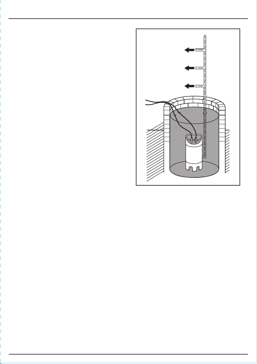
9.5 PLACEMENT - FIGS. 9 - 11
The pump must be fully submersed before
the power is switched on. DO NOT turn on
when dry.
FIG.9
When submersing or lifting the pump it will be
necessary to use a rope or chain, this must be
attached to the transport handle.
If pumping water from a sandy or muddy floor
bed, the pump can be suspended using a rope
or chain (not supplied) fixed to the handle. DO
NOT use any of the electrical cables for this
purpose.
When pumping flood water from a room or cellar,
installation of the pump should be in a drain well
(if possible).
FIG.10
FIG.11
- 16 -
Page 17

9. INSTALLING THE PUMP
9.6 CONNECTING TO POWER VIA RCD –
FIG.12
Once you have the pump safely situated and the float
switch adjusted, if required, you are ready to turn on
the pump.
Plug your pump into a Residual Current Device
(RCD) such as Draper Stock No.69307 or 89301
and connect to your mains supply.
9.7 SWITCHING ON THE PUMP
On switching on your socket, the pump will begin to operate (if water level high enough to operate
the float switch). The pump will begin to expel the water via your hoseand once the water level
drops to the required level, the float switch will automatically switch off the pump.
*Note. Stock No.98911 is not supplied with a float switch.
FIG.12
RCD’s sold separately
- 17 -
Page 18

10. MAINTENANCE
10.1 CLEARING OBSTRUCTIONS IN
THE IMPELLER HOUSING – FIG.13
WARNING: For your own safety, remove plug from
power supply before maintaining your submersible
pump.
- If the impeller becomes blocked or obstructed,
remove base plate by removing the screws.
- DO NOT lever the impeller as this will cause
damage due to its brittle construction.
- Take note of the orientation and order with which
the components were removed to ensure the
correct re-assembly.
- Rinse with clean water to flush.
NOTE: This pump is fitted with an overload safety
device. In the event of the motor overheating, the
device will automatically switch off. Allow to cool for
20 minutes before attempting to restart.
FIG.13
- 18 -
Page 19

11. OPTIONAL ACCESSORIES
Layflat Hoses:
Stock No. Part No. size Length Description
36919 ASWP1 25mm. I.D. 5m. Hobby/DIY Hose
45343 ASWP3 25mm. I.D. 10m. Heavy Duty Hose
36947 ASWP4 32mm. I.D. 10m. Heavy Duty Hose
- 19 -
Page 20

12. TROUBLESHOOTING
12.1 TROUBLESHOOTING CHECKLIST
WARNING:
For your own safety, always turn the main switch on the machine "Off" and remove the plug from
the power supply before carrying out any servicing or maintenance.
Motor does not
start or makes no
sound
The pump delivers
no water
The pump does not
stop
The flow rate is too
low
1. Make sure the motor is
powered
2. The pump is disabled by
the float
1. The suction grid or piping
are clogged.
2. The impeller is worn or
stuck.
3. The head height exceeds
the pump specification.
4. Water level under the
suction minimum.
1. The pump is not disabled
by the float.
1. Make sure the suction
grid is not partially
clogged.
2. Make sure the impeller or
delivery pipe are not
partially clogged or fouled.
3. Flow direction control
valve orientation incorrect.
Service agent.
1. Make sure the float can move
freely.
2. Increase depth of the water.
1. Remove the obstruction.
2. Replace the impeller or remove the
obstruction.
3. Reduce head height.
4. Insert into water or dig well to
move pump lower.
1. Make sure the float can move
easily.
2. Float disabled (locked).
1. Remove any obstructions.
2. Remove any obstructions.
3. Check and replace if necessary.
The pump stops
running
1. Intervention of the thermal
overload switch.
- 20 -
1. Make sure the fluid being pumped
is not too dense, causing the motor
to overheat.
2. Make sure the temperature of the
water is not too high.
3. Make sure there is no solid body
obstructing the impeller.
4. Power supply doesn’t comply with
the nameplate’s data.
Page 21

13. EXPLANATION OF SYMBOLS
13.1 EXPLANATION OF SYMBOLS
Single value noise marking.
(Maximum declared
96
A-Weighted sound power level
in decibels).
Do not dispose of WEEE*
unsorted municipal waste.
Class II construction
(Double insulated).
Warning!
Read the instruction manual.
Warning!
Not to be used in fish ponds.
- 21 -
Page 22

14. DISPOSAL
14.1 DISPOSAL
– At the end of the machine’s working life, or when it can no longer be repaired, ensure that it is
disposed of according to national regulations.
– Contact your local authority for details of collection schemes in your area.
In all circumstances:
Do not dispose of power tools with domestic waste.
•
Do not incinerate.
•
Do not abandon in the environment.
•
Do not dispose of WEEE* as unsorted municipal waste.
•
* Waste Electrical & Electronic Equipment.
- 22 -
Page 23

CONTACTS
Draper Tools Limited, Hursley Road,
Chandler's Ford, Eastleigh, Hampshire. SO53 1YF. U.K.
Helpline: (023) 8049 4344
Sales Desk: (023) 8049 4333
Internet: drapertools.com
E-mail: sales@drapertools.com
General Enquiries: (023) 8026 6355
Service/Warranty Repair Agent:
For aftersales servicing or warranty repairs, please contact the
Draper Tools Helpline for details of an agent in your local area.
YOUR DRAPER STOCKIST
KCMC0319
©Published by Draper Tools Limited.
No part of this publication may be reproduced, stored in a retrieval system or transmitted in any form or by any means,
electronic, mechanical photocopying, recording or otherwise without prior permission in writing from Draper Tools Ltd.
 Loading...