

Page 1

20V BRUSHLESS 1/2" SQ. DR.
MID-TORQUE
IMP A CT
WRENCH
55365 & 97777
These instructions accompanying the product are the original instructions. This document is part of the product, keep
it for the life of the product passing it on to any subsequent holder of the product. Read all these instructions before
assembling, operating or maintaining this product.
This manual has been compiled by Draper Tools describing the purpose for which the product has been designed,
and contains all the necessary information to ensure its correct and safe use. By following all the general safety
instructions contained in this manual, it will ensure both product and operator safety, together with longer life of the
product itself.
AlI photographs and drawings in this manual are supplied by Draper Tools to help illustrate the operation of the
product.
Whilst every effort has been made to ensure the accuracy of information contained in this manual, the Draper Tools
policy of continuous improvement determines the right to make modifications without prior warning.
Page 2

1. TITLE PAGE
1.1 INTRODUCTION:
USER MANUAL FOR: 20V Brushless ½" Sq. Dr. Mid-Torque Impact Wrench
Stock No’s: 55365 & 97777
Part No’s: D20IW400 & D20IW400SET
1.2 REVISIONS:
Date first published November 2019.
As our user manuals are continually updated, users should make sure that they use
the very latest version.
Downloads are available from: http://drapertools.com/manuals
Draper Tools Limited
Hursley Road
Chandler’s Ford
Eastleigh
Hampshire
SO53 1YF
UK
Website: drapertools.com
Product Help Line: +44 (0) 23 8049 4344
General Fax: +44 (0) 23 8026 0784
1.3 UNDERSTANDING THIS MANUALS SAFETY CONTENT:
WARNING! – Information that draws attention to the risk of injury or death.
CAUTION! – Information that draws attention to the risk of damage to the product or
surroundings.
1.4 COPYRIGHT © NOTICE:
Copyright © Draper Tools Limited.
Permission is granted to reproduce this publication for personal and educational use
only. Commercial copying, redistribution, hiring or lending is prohibited.
No part of this publication may be stored in a retrieval system or transmitted in any
other form or means without written permission from Draper Tools Limited.
In all cases this copyright notice must remain intact.
Page 3

2. CONTENTS
1 TITLE PAGE
1.1 INTRODUCTION ......................................................................................................................2
1.2 REVISION HISTORY................................................................................................................ 2
1.3 UNDERSTANDING THIS MANUAL .........................................................................................2
1.4 COPYRIGHT NOTICE..............................................................................................................2
2 CONTENTS
2.1 CONTENTS..............................................................................................................................3
3 WARRANTY
3.1 WARRANTY............................................................................................................................. 4
4 INTRODUCTION
4.1 SCOPE.....................................................................................................................................5
4.2 SPECIFICATION......................................................................................................................5
4.3 HANDLING AND STORAGE ....................................................................................................6
5 HEALTH AND SAFETY INFORMATION
5.1 GENERAL SAFETY INSTRUCTIONS FOR POWER TOOL USE ...........................................7
5.2 SPECIFIC SAFETY INSTRUCTIONS FOR IMPACT WRENCH USE......................................8
5.3 RESIDUAL RISK ......................................................................................................................9
5.4 SAFETY INSTRUCTIONS FOR MAINS POWERED BATTERY PACKS
AND CHARGERS.....................................................................................................................9
5.5 CONNECTION TO THE POWER SUPPLY (CHARGER) ...................................................... 11
6 TECHNICAL DESCRIPTION
6.1 IDENTIFICATION...................................................................................................................12
7 UNPACKING AND CHECKING
7.1 PACKAGING ..........................................................................................................................13
7.2 D20 MULTI-TOOL INTERCHANGEABLE BATTERY SYSTEM .............................................13
7.3 WHAT’S IN THE BOX.............................................................................................................13
8 PREPARING THE IMPACT WRENCH
8.1 BATTERY PACK CHARGING ..............................................................................................14
8.2 BATTERY PACK PROTECTION FEATURES ........................................................................15
8.3 BATTERY PACK CHARGE STATUS......................................................................................15
8.4 BATTERY LIFE EFFICIENCY AND CHARGING ADVICE .....................................................15
9 BASIC IMPACT WRENCH OPERATIONS
9.1 INSTALLING AND REMOVING SOCKETS............................................................................16
9.2 ROTATIONAL DRIVE SELECTION........................................................................................16
9.3 VARIABLE TORQUE CONTROL ...........................................................................................17
9.4 VARIABLE SPEED TRIGGER................................................................................................17
9.5 BELT CLIP.............................................................................................................................. 17
9.6 LED WORKLIGHT..................................................................................................................18
9.7 OPERATION...........................................................................................................................18
10 MAINTENANCE AND TROUBLESHOOTING
10.1 MAINTENANCE .....................................................................................................................19
10.2 TROUBLESHOOTING ...........................................................................................................19
11 OPTIONAL ACCESSORIES
11.1 OPTIONAL ACCESSORIES...................................................................................................20
12 DISPOSAL
12.1 DISPOSAL..............................................................................................................................21
12.2 BATTERY DISPOSAL INFORMATION...................................................................................21
13 EXPLANATION OF SYMBOLS
13.1 EXPLANATION OF SYMBOLS ..............................................................................................22
DECLARATION OF CONFORMITY ....................................................................................... ENCLOSED
- 3 -
Page 4

3. WARRANTY
3.1 WARRANTY
Draper tools have been carefully tested and inspected before shipment and are guaranteed to be
free from defective materials and workmanship.
Should the tool develop a fault, please return the complete tool to your nearest distributor or
contact
Draper Tools Limited, Chandler's Ford, Eastleigh, Hampshire, SO53 1YF. England.
Telephone Sales Desk: (023) 8049 4333 or Product Help Line (023) 8049 4344.
A proof of purchase must be provided with the tool.
If upon inspection it is found that the fault occurring is due to defective materials or workmanship,
repairs will be carried out free of charge. This warranty period covering labour is 12 months from
the date of purchase except where tools are hired out when the warranty period is 90 days from
the date of purchase. The warranty is extended to 24 months from the date of purchase for parts
only. This warranty does not apply to any consumable parts, any type of battery or normal wear
and tear, nor does it cover any damage caused by misuse, careless or unsafe handling,
alterations, accidents, or repairs attempted or made by any personnel other than the authorised
Draper warranty repair agent.
Note: If the tool is found not to be within the terms of warranty, repairs and carriage charges will
be quoted and made accordingly.
This warranty applies in lieu of any other warranty expressed or implied and variations of its terms
are not authorised.
Your Draper warranty is not effective unless you can produce upon request a dated receipt or
invoice to verify your proof of purchase within the warranty period.
Please note that this warranty is an additional benefit and does not affect your statutory rights.
Draper Tools Limited.
- 4 -
Page 5

4. INTRODUCTION
4.1 SCOPE
This hand-held cordless impact wrench is intended to tighten and loosen mechanical fixings (nuts,
bolts, etc).
As part of our core range, this product is suitable for enthusiasts and tradespeople alike. Any
application other than that it was intended for, is considered misuse.
4.2 SPECIFICATION
Stock No’s. .................................................................................................................55365 & 97777
Part No’s................................................................................................ D20IW400 & D20IW400SET
Revolutions per minute (no load): ............................................................................... 0 – 2,200r/min
Anvil: ............................................................................................................................................1/2"
Clutch: ...........................................................................................................................Twin hammer
Maximum torque (±10%): .................................................................................... 400Nm/295.29lbs-ft
Adjustable torque (±10%):......... 5 Fixed settings from low torque (100Nm), to high torque (400Nm)
Impact rate: .................................................................................................................. 0 – 3,300bpm
Sound pressure level (LpA)*: .............................................................................................. 96dB(A)
Sound power level (LWA)**: ............................................................................................... 107dB(A)
Uncertainty (K): ............................................................................................................ 3dB(A)
Vibration level (main handle):.............................................................................................. 19.1m/s²
Uncertainty (K) ............................................................................................................ 1.5m/s²
Maximum running time (no load)....................................................................... 60 minutes (approx.)
Weight (machine only):............................................................................................................ 1.55kg
Battery pack: 00649 (sold separately for 55365)
Part No.: ................................................................................................................. D20B3.0AH
Type:................................................................................................................................. Li-ion
Rated voltage: .....................................................................................................................20V
Rating: ............................................................................................................................2
Charger: 60559 (sold seperately for 55365)
Part No.: ...................................................................................................................... D20BCS
Rated voltage ..................................................................................................................230V~
Rated frequency................................................................................................................ 50Hz
Rated output.......................................................................................................................40W
Rated D.C. output voltage ................................................................................................... 20V
Rated D.C. output current ................................................................................................ 1.65A
Protective device rated current.............................................................................................. 8A
Construction .................................................................................................................. Class II
* Continuous A-Weighted Sound Pressure Level at the workstation in accordance to and declared
according to EN62841.
** The typical A-Weighted noise level determined to EN62841.
×
3Ah
- 5 -
Page 6

4. INTRODUCTION
4.3 HANDLING AND STORAGE
– Care must be taken when handling this product.
● Dropping this power tool could have an effect on its accuracy and could also result in
personal injury. This product is not a toy and must be respected.
– Environmental conditions can have a detrimental effect on this product if neglected.
● Exposure to damp air can gradually corrode components.
● If the product is unprotected from dust and debris, components will become clogged.
● If not cleaned and maintained correctly or regularly, the machine will not perform at its best.
- 6 -
Page 7

5. HEALTH AND SAFETY INFORMATION
5.1 GENERAL SAFETY INSTRUCTIONS FOR POWER TOOL USE
When using any type of power tool there are steps that should be taken to make sure that you, as
the user, remain safe.
Common sense and a respect for the tool will help reduce the risk of injury.
Read the instruction manual fully.
understood this manual.
Most important you must know how to safely start and stop this machine, especially in an
emergency.
Keep the work area tidy and clean.
use will reduce your concentration. Mess on the floor creates a trip hazard. Any liquid spilt on the
floor could result in you slipping.
Find a suitable location.
natural light or artificial lighting as a replacement. Avoid damp and dust locations as it will have a
negative effect on the machine’s performance. If the machine is portable do not expose the tool to
rain. In all cases do not operate power tools near any flammable materials.
Keep bystanders away.
work area for their own protection. The barrier must extend a suitable distance from the tool user.
Unplug and house all power tools that are not in use.
unattended while connected to the power supply. They must be housed in a suitable location,
away locked up and from children. This includes battery chargers.
Do not overload or misuse the tool.
they are capable of doing. Do not attempt to use a power tool (or adapt it in any way) for an
application it is not designed for. Select a tool appropriate for the size of the job. Overloading a tool
will result in tool failure and user injury. This covers the use of accessories.
Dress properly.
become entangled in moving machinery. This can also result in parts of body being pulled into the
machine. Clothing should be close fitted, with any long hair tired back and jewellery and neck ties
removed. Footwear must be fully enclosed and have a non-slip sole.
Wear personal protective equipment (PPE).
if not suitably protected against. If the work involving the power tool creates dust or fumes wear a
dust mask. Vibration to the hand, caused by operating some tools for longer periods must be
protected against. Wear vibration reducing gloves and allow long breaks between uses. Protect
against dust and swarf by wearing approved safety goggles or a face shield. These are some of
the more common hazards and preventions, however, always find out what hazards are
associated with the machine/work process and wear the most suitable protective equipment
available.
Do not breathe contaminated air.
possible) to an extraction system either locally or remotely. Working outdoors can also help if
possible.
Move the machine as instructed.
cable. If the product is heavy, employ a second or third person to help move it safely or use a
mechanical device. Always refer to the instructions for the correct method.
Do not overreach.
could be from a height or onto a machine and will result in injury.
Maintain your tools correctly.
or missing parts immediately with original parts from the manufacturer. As applicable, keep blades
sharp, moving parts clean, oiled or greased, handles clean, and emergency devices working.
Loose clothing, long hair and jewellery are all dangerous because they can
If the machine is bench mounted, the location should provide good
Children, onlookers and passers by must be restricted from entering the
Extending your body too far can result in a loss of balance and you falling. This
Do not attempt any operation until you have read and
Attempting to clear clutter from around the machine during
A power tool should never be left
All tools are designed for a purpose and are limited to what
Dust, noise, vibration and swarf can all be dangerous
If the work creates dust or fumes connect the machine (if
If the machine is hand held, do not carry it by the power supply
A well maintained tool will do the job safely. Replace any damaged
- 7 -
Page 8

5. HEALTH AND SAFETY INFORMATION
Wait for the machine to stop.
continue to move due to momentum. Wait for all parts to stop, then unplug it from the power
supply before making any adjustments, carrying out maintenance operations or just finishing using
the tool.
Remove and check setting tools.
set, load or adjust the power tool. Before starting the power tool always check to make certain they
have been removed and are safely away from the machine.
Prevent unintentional starting.
the switch is in the OFF position. If the machine is portable, do not hold the machine near the
switch and take care when putting the machine down, that nothing can operate the switch.
Carefully select an extension lead.
If the tool is designed for use outdoors, use an extension lead also suitable for that environment.
When using an extended lead, select one capable of handling the current (amps) drawn by the
machine in use. Fully extend the lead regardless of the distance between the power supply and
the tool. Excess current (amps) and a coiled extension lead will both cause the cable to heat up
and can result in fire.
Concentrate and stay alert.
tool if you are under the influence of drugs (prescription or otherwise), including alcohol or if you
are feeling tired. Being disorientated will result in an accident.
Have this tool repaired by a qualified person.
international and local standards and as such should be maintained and repaired by someone
qualified, using only original parts supplied by the manufacturer. This will ensure the tool remains
safe to use.
Unless the machine is fitted with a safety brake, some parts may
Some machinery requires the use of additional tools or keys to
Before plugging any machine in to the power supply, make sure
Some machines are not suitable for use with extension leads.
Distractions are likely to cause an accident. Never operate a power
This tool is designed to conform to the relevant
5.2 SPECIFIC SAFETY INSTRUCTIONS FOR IMPACT WRENCH USE
Important:
any application other than that for which it was designed. If you are unsure of its relative
applications do not hesitate to contact us in writing and we will advise you.
– Power tools shall not be used in potentially explosive atmospheres unless specifically designed
– Unexpected tool movement due to reaction forces or breakage of inserted tool or reaction bar
– Power tools shall be isolated from the energy source before changing or adjusting the inserted
Warning!
● There is a risk of crushing by torque between a reaction bar and the workpiece.
● There is a risk of loose clothing, hair etc., being caught in the rotating spindle of the power
● There is a risk of being injured if hands are not kept away from the reaction bar, specially
● There is a risk of being injured if hands are not kept away from the impact socket.
● There is a risk of danger to persons from high speed splinters being emitted from impact
– Use only sockets and adaptors which are in good condition and are intended for use with
– Adopt a suitable posture to counteract normal or unexpected movement of the power tool due
Draper Tools Limited recommends that this machine should not be modified or used for
for that purpose.
may cause injuries.
tool.
supply tool.
observed when unscrewing in confined work spaces.
wrenches in the case of socket failure. Only use properly hardened impact sockets with this
machine.
impact wrenches.
to reaction forces from the power assembly tool.
- 8 -
Page 9

5. HEALTH AND SAFETY INFORMATION
– Ensure the anvil ring is correctly maintained and if damaged or missing, is replaced
immediately before work commences. Missing or damaged anvil rings may lead to sockets
detaching from the wrench while rotating at high speed.
– Only use accessories specifically hardened for impact use. Do not use standard chrome type
hand tool sockets as they will shatter and splinter causing injury.
– Do not modify this impact wrench in any way.
– When starting or finishing the removal and installation of fasteners there is a risk of crushing
between the tool and the workpiece due to sudden movement or reaction forces.
5.3 RESIDUAL RISK
Important:
instructions of safe working with power tools, every power tool involves a certain residual risk
which can not be completely excluded by safety mechanisms. Power tools must therefore always
be operated with caution!
5.4 SAFETY INSTRUCTIONS FOR MAINS POWERED BATTERY PACKS
& CHARGERS
Chargers
– The charger is for indoor use only.
– Prior to plugging the charger in to the supply, check that the plug and the cable are in good
– Only use a correctly rated mains outlet to provide power, do not plug into site generators,
– Use the correct Draper charger in conjunction with it’s corresponding battery pack (consult the
– Do not charge any other batteries with Draper chargers. Any other application is considered
– Do not attempt to charge battery packs that are too hot (over 30ºC) or too cold (under 5ºC), if
– Set up the charger and cable in a safe place where it won’t be knocked, tripped over, stepped
– Inspect the battery pack for damage, if it is undamaged, plug it into the charger, ensuring the
– Switch the charger on and check that the correct indicators illuminate, allow the battery pack to
Caution:
Once the charging has been completed, give 15 minutes rest until the next charge.
– After charging is complete, unplug the charger from the socket outlet by pulling on the plug. Do
Although the safety instructions and operating manuals for our tools contain extensive
repair. If either are damaged, have the defective item replaced immediately by a suitably
qualified person. If the casing of the battery charger is damaged, it is good policy to have the
charger checked over by a suitably qualified person.
attach to engine generators or D.C. sources. Do not use a mains socket outlet that is not
switched.
Draper website for more information or to find your local stockist).
misuse.
these conditions apply set the battery pack aside to “normalise” before proceeding with the
charging operation.
on, etc. and where it is well ventilated. Make sure the ventilation slots in the charger case are
not obstructed, plug the charger into the socket outlet.
correct orientation. (Most chargers and batteries have ‘keys’ etc, to make sure the battery pack
is not inserted incorrectly, if you are having to ‘force’ the battery pack into the charger, the
chances are you have it the wrong way round, check and try again.)
charge (see the specific instructions for your charger). Once charging is complete, switch the
charger off, remove the battery pack and store, repeat the procedure if you have more than
one battery pack to charge.
When the battery charger has been continuously used, the battery charger will be hot.
not pull on the cable. Store the charger in a dry secure place.
- 9 -
Page 10

5. HEALTH AND SAFETY INFORMATION
– If, when the charger was switched on, the correct indications did not occur, leave for two or
three minutes to allow the charger to stabilise, if the correct indications occur, allow the
charging cycle to proceed as normal. If no indication appears at all, switch off, remove the
battery pack, unplug the charger, check that the charger contacts and the battery contacts are
clean and repeat the process. If there is still no indication, switch off, remove the battery pack,
unplug the charger and check the fuse. If the fuse is blown, replace and repeat the process. If
the fuse blows again, or if the fuse was intact, attempt no further action. Refer the charger to a
suitably qualified person for repair.
Battery packs
– Before charging, read the instructions.
– For indoor use. Do not expose to rain.
– Only use Draper D20 battery packs with this product. Consult your Draper stockist for details.
– Do not charge any other manufacturer’s battery packs using Draper chargers. Any other
application is considered misuse.
– The battery must be removed from the appliance before it is recycled.
– The charger must be disconnected from the supply mains when removing the battery.
– The battery is to be disposed of in-line with local authority procedures.
– Do not use any other than the designated Draper batteries/chargers with this product.
– Do not crush, open or burn the battery. Exposure to potentially harmful materials may occur.
– In case of fire use CO2 or dry chemical extinguisher.
– Do not expose to high temperatures >50°C. The battery may degrade at high temperatures.
– Charge battery in conditions between 5°C to 30°C with the specified charger designed for this
battery.
– Do not use battery if it has been stored at 5°C or less. Allow it to “normalise” at room
temperature before usage/charging.
Warning!
– Leaking battery packs
● The electrolyte in battery packs is corrosive. Avoid contact with the skin.
● If contact is made, flush the area with running water, pat dry and seek medical attention and
advice at the earliest opportunity.
● Inform medical personnel that the contaminant is a “high alkaline, corrosive liquid”.
● If electrolyte comes into contact with the eyes, flush with copious amounts of water only.
Seek medical attention immediately, relaying the information above.
- 10 -
Page 11

5. HEALTH AND SAFETY INFORMATION
5.5 CONNECTION TO THE POWER SUPPLY (CHARGER)
Caution:
This appliance is supplied with a moulded 3 pin mains plug for your safety. The value of the fuse
fitted is marked on the pin face of the plug. Should the fuse need replacing, ensure the substitute
is of the correct rating, approved to BS1362 and ASTA or BSI Kite marked.
ASTA
BSI
The fuse cover is removable with a small plain slot screwdriver. Ensure the fuse cover is replaced
before attempting to connect the plug to an electrical outlet. If the cover is missing, a replacement
must be obtained or the plug replaced with a suitable type.
If a replacement plug is to be fitted this must be carried out by a qualified electrician.
The damaged or incomplete plug, when cut from the cable should be disabled to prevent
connection to a live electrical outlet.
This appliance is Class II
on the rating label and compatible with the plug fitted.
†
Double insulated : This product requires no earth connection as supplementary insulation is
applied to the basic insulation to protect against electric shock in the event of failure of the basic
insulation.
Important:
If using an extension lead, follow the instructions that came with your lead regarding maximum
load while cable is wound. If in doubt, ensure that the entire cable is unwound. Using a coiled
extension lead will generate heat which could melt the lead and cause a fire.
Risk of electric shock. Do not open.
†
and is designed for connection to a power supply matching that detailed
- 11 -
Page 12

6. TECHNICAL DESCRIPTION
6.1 IDENTIFICATION
1/2" Square drive.
‘ON/OFF’ Trigger switch.
Soft grip.
Variable torque control.
LED Worklight.
Belt clip.
Forward/reverse switch.
- 12 -
Page 13

7. UNPACKING AND CHECKING
7.1 PACKAGING
Carefully remove the product from the packaging and examine it for any sign of damage that may have
happened during shipping. Lay the contents out and check them against the parts shown below. If any
part is damaged or missing, please contact the Draper Help Line (the telephone number appears on
the Title page) and do not attempt to use the product.
The packaging material should be retained at least during the warranty period, in case the machine
needs to be returned for repair.
Warning!
● Some of the packaging materials used may be harmful to children. Do not leave any of these
● If any of the packaging is to be thrown away, make sure they are disposed of correctly,
7.2 D20 MULTI-TOOL INTERCHANGEABLE
BATTERY SYSTEM
The D20 range of tools are a range of tools suitable for
enthusiasts and tradespersons alike, featuring a wide array of
machines all running from the same range of batteries. Many
different capacity batteries are available making sure you can
balance tool weight with longevity and find a battery that meets
your needs. To find out the latest range of accessories including
batteries and chargers please consult the Draper website for
more information or to find your local Draper stockist.
7.3 WHAT’S IN THE BOX
55365 is supplied as ‘BARE’ machine with
no batteries or charger.
If you have purchased 97777, the box will
also include 2
charger (60559).
materials in the reach of children.
according to local regulations.
×
3Ah batteries (00649) and
MULTI-TOOL BATTERY SYSTEM
- 13 -
Page 14

8. PREPARING THE IMPACT WRENCH
8.1 BATTERY PACK CHARGING –
FIGS. 1 – 2
This power product is either supplied “bare”,
without battery pack or charger (Stock No.55365),
or with a transformer/charger and 2 battery
packs (Stock No.97777).
Important:
and chargers can be used in conjunction with this
product. Use of any other third party battery
packs/chargers with this product is considered
misuse and will invalidate the product’s warranty.
Once connected to the mains supply, recharging of
the battery can be left generally unsupervised,
requiring minimal attention. Complex circuit
construction monitors the battery condition,
adjusting the recharge current to suit. When the
recharge cycle is complete, to maintain the full
capacity, a low output current will continue as
required.
Warning!
battery prior to each charge. If there is any sign of
damage then do not commence charging, seek
advice from Draper Tools.
The battery pack is supplied un-charged and must
be charged before initial use.
To charge the battery pack
removed from the tool.
To release the battery pack:
– Press the battery release button
– Plug the battery charger
– The red LED
– Slide the battery into the charger (the battery is shaped to fit into the charger one way only.
– After a few seconds delay, the red LED
– Whilst the battery is charging, the green LED
– The battery is fully charged when the green LED stops flashing and remains a constant green.
Caution:
the plug when removing from power supply to avoid damaging the cord.
To remove the battery from the battery charger:
– Supporting the battery charger with hand, pull out the battery from the battery charger.
Caution:
been completed, leave the charger 15 minutes to cool until next use.
Only Draper designated battery packs
Check the condition of the charger and
, it must first be
slide the battery pack off (Fig.1).
unit into a 230V/AC 13amp three pin supply socket.
will illuminate to show the charger has power.
illuminate solid red.
to constant red.
The red LED will extinguish.
Do not pull the plug out of the power supply by pulling on the cord. Make sure to grasp
If the battery charger has been in continuous use it will be hot. Once the charging has
and gently
will flash to show that charging has begun, then
FIG.1
FIG.2
will flash, (the red LED will go from flashing
- 14 -
Page 15

8. PREPARING THE IMPACT WRENCH
If the battery is charged when it is warm due to
battery use or exposure to sunlight, the battery will
not be recharged. In such a case, let the battery
cool before charging.
If the red indicator flickers rapidly at 0.2 second
intervals, check or and remove any foreign objects
in the charger’s battery slot. If there are no foreign
objects, it is probable that the battery or charger is
malfunctioning. Allow battery/charger to normalise
and try again. If a fault remains after trying this
then contact Draper Tools.
8.2 BATTERY PACK PROTECTION
FEATURES
Overcharging protection:
ensures that the battery pack can never be
overcharged. When the battery pack reaches full
charge capacity, the transformer/charger will
automatically shut off, protecting the internal
components from being damaged.
Over-discharging protection:
the battery pack from discharging beyond the
recommended lowest safety voltage.
Overheating protection:
an internal thermistor cut-off sensor which shuts off
the battery pack should it become too hot during
operation. This can happen if the tool is overloaded
or being used for extended periods. Up to 30
minutes cooling time may be required, depending
on ambient temperature.
Current protection:
overloaded and the maximum current draw be
exceeded, the battery will shut off to protect the internal components. The battery pack will resume
working once excessive current draw has returned to normal, safe level.
Short circuit protection:
protection would immediately stop the battery pack from operating.
This feature that
This feature will stop
The battery pack contains
Should the battery be
If, for any reason, the battery pack was to short circuit, the short circuit
8.3 BATTERY PACK CHARGE STATUS – FIG. 3
To display the amount of charge left in the battery pack, press the charge level indicator button .
8.4 BATTERY LIFE EFFICIENCY AND CHARGING ADVICE
– Avoid recharging at high temperatures.
A rechargeable battery will be hot immediately after use. If such a battery is recharged
immediately after use, its internal chemical substance will deteriorate, and the battery life will
be shortened. Leave the battery and recharge it after it has cooled for a while.
– The battery should only be used and/or charged when battery temperature is between 5°C and
30°C.
– The battery needs to be warmed-up or cooled down in order to prevent damage to the
batteries internal components.
Note:
If battery is too hot or too cold, allow it to ‘normalise’ before use or charging.
Note:
Failure to warm up or cool down a battery could result in serious damage to the battery,
charger and user.
- 15 -
Charge level
indicator
FIG.3
Amount of charge
remaining
0 – 10%
10 – 25%
25 – 50%
50 – 75%
75 – 100%
Page 16

9. BASIC IMPACT WRENCH OPERATIONS
9.1 INSTALLING AND REMOVING
SOCKETS – FIG.4
This wrench is supplied with a 1/2" Square drive
.
Make sure to always use specific “Impact”
sockets or accessories with this tool, use of
chrome vanadium non-impact sockets could
result in damage to your tool and/or personal
injury.
To fit a socket:
– Roughly align the hole in the impact socket with
the sprung loaded ball detent
square drive anvil
– Push fit the socket over the anvil. The mechanism
holds the socket securely in place.
To remove a socket:
– Pull the socket away from the anvil to remove.
Note:
Extra effort may be required when fitting and
removing brand new sockets on their initial usage.
.
located on the
9.2 ROTATIONAL DRIVE SELECTION –
FIG.5
The forward/reverse drive selector switch
determines the direction of rotation of the drive, i.e.
clockwise or anticlockwise.
To alter the direction of rotation:
– Stop the machine and push switch
left or right.
– When the direction switch is pushed to the left,
the drive will rotate clockwise.
– When the switch is pushed to the right, the
drive will rotate anticlockwise.
– Before operation, check that the switch is set in
the required position. Do not change the
direction of rotation until the wrench comes to a
complete stop.
– When the wrench is not in use move the
direction switch to the neutral position (the
middle setting) to lock the trigger out.
Note:
Failure to use the neutral position may
activate the trigger inadvertently. This inadvertent
operation may cause the wrench to become
damaged.
to the
FIG.4
FIG.5
- 16 -
Page 17

9. BASIC IMPACT WRENCH OPERATIONS
9.3 VARIABLE TORQUE CONTROL
– FIG.6
The impact wrench has 5 pre-set torque settings,
ranging from high to low:
– Press the variable torque adjustment button
to select the required torque setting. Each
torque setting is indicated on the torque setting
display
– The display features 5 LED numbers that
illuminate incrementally from high torque to low
torque, each time the torque adjustment button
is pressed.
– High torque (circa 400Nm) – is No.5 on the left,
through to low torque, No.1 (circa 100Nm) – the
last on the right.
– The 3 lights between indicate the intermediate
torque settings.
.
9.4 VARIABLE SPEED TRIGGER
– FIG. 7
When the trigger
rotate (provided the direction switch
the forward or reverse position). The rotational
speed varies with the torque adjustment.
This trigger switch is electronic which enables the
user to vary the speed continuously.
– The speed varies according to how far the
trigger switch is depressed.
– The further it is depressed, the faster the drive
spindle will rotate.
– The lighter it is depressed, the slower it will
rotate.
Note:
It may be necessary to initially release fixings
with a hand tool prior to using the impact wrench.
Note:
Always tighten fixings to the correct torque
as indicated by the manufacturer using a calibrated
torque wrench. Failure to do so may result in the
fixing becoming damaged or insufficiently
tightened.
Note:
This product is equipped with an electric brake.
is depressed, the drive will
is set in
9.5 BELT CLIP – FIG. 8
The spring steel belt clip
installed on either side of the tool.
To install the clip:
– Locate the clip
strip the thread.
is convenient for hanging the drill temporarily. The clip can be
in position and fasten with screw supplied, take care to not over-tighten and
FIG.6
FIG.7
FIG.8
- 17 -
Page 18

9. BASIC IMPACT WRENCH OPERATIONS
9.6 LED WORKLIGHT – FIG.9
To aid use in confined and inadequately lit spaces,
the LED worklight
when the trigger is activated.
automatically illuminates
9.7 OPERATION
Proper fastening torque is determined by the kind
of fastening, the size of the fastening or the
material or workpiece.
– It is advisable to perform a test operation to
determine the proper fastening time for the
fastening you are using.
– Hold the wrench in straight alignment to the
fastening.
– Depress the wrench and use for the required amount of time.
– After fastening, always check the torque with an appropriate torque wrench.
Note:
Do not use this tool to install wheel nuts on wheels without a torque limiting device. Doing so
could result in galled or broken nuts.
Note:
Using a universal joint or extension bar may reduce the fastening force of the impact wrench
and require longer fastening time.
Note:
Using an impact wrench creates heat. The metal housing at the front of the wrench will
become hot. In certain circumstances, the force required to tighten or remove fixings may cause
the fixings themselves to become very hot! Wear suitable gloves to prevent burns.
FIG.9
- 18 -
Page 19

10. MAINTENANCE AND TROUBLESHOOTING
10.1 MAINTENANCE
Regular inspection and cleaning reduces the necessity for maintenance operations and will keep
your tool in good working condition.
The motor must be correctly ventilated during tool operation. Avoid blocking the air inlets and
vacuum the ventilation slots regularly.
10.2 TROUBLESHOOTING
Note:
Remove the battery pack before carrying out adjustment, servicing or maintenance.
Problems Possible cause Required action
Motor does not start. – Battery pack no charge.
– Battery faulty or
damaged.
Motor runs, but slowly/ losing
power.
Battery pack doesn’t charge
non-llumination / non
illumination of charger.
– Battery pack no charge.
– Battery pack faulty or
damaged.
/
– Fuse blown in charger
plug.
– Charger faulty.
– Re-charge battery.
– Replace battery.
– Re-charge battery.
– Replace battery.
– Replace fuse.
– Replace charger.
- 19 -
Page 20

11. OPTIONAL ACCESSORIES
11.1 OPTIONAL ACCESSORIES
A full range of accessories are available from Draper Tools.
Please visit our website for details: www.drapertools.com
- 20 -
Page 21

12. DISPOSAL
12.1 DISPOSAL
– At the end of the machine’s working life, or when it can no longer be repaired, ensure that it is
disposed of according to national regulations.
– Contact your local authority for details of collection schemes in your area.
In all circumstances:
● Do not dispose of power tools with domestic waste.
● Do not incinerate.
● Do not dispose of WEEE* as unsorted municipal waste.
Li-ion
* Waste Electrical & Electronic Equipment.
12.2 BATTERY PACK DISPOSAL INFORMATION
Warning!
● Do not put battery pack in fire or mutilate – cells may burst or release toxic materials.
● Do not short circuit cells, may cause burns.
● The battery pack must be removed from the appliance before it is scrapped.
● The battery pack is to be disposed of safely.
● Do not mutilate batteries, corrosive electrolyte will be released.
● Do not dispose of batteries or cells in a charged condition.
Expired batteries must be recycled/disposed of in accordance with the appropriate regulation or
legislation. They should be returned to your local warranty agent/stockist.
- 21 -
Page 22
++++++
+++++++
++++++++
++++++++
++++++++
++++++++
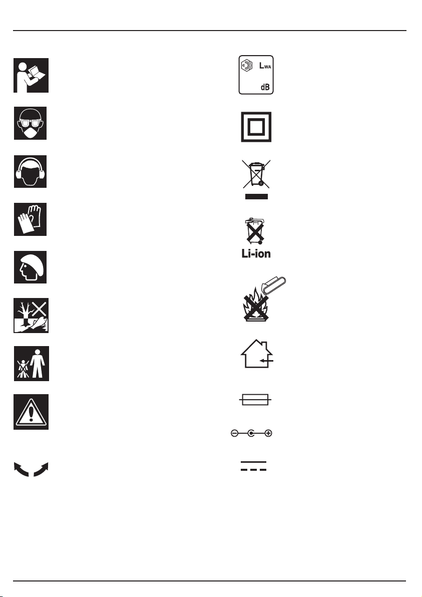
13. EXPLANATION OF SYMBOLS
13.1 EXPLANATION OF SYMBOLS
Read the instruction manual.
83
Single value noise marking.
(Maximum declared A-Weighted
sound power level in decibels).
Wear face mask and safety
glasses.
Wear ear defenders.
Wear protective gloves.
Long and loose hair must be
contained or securely tied back.
Do not abandon into the
environment.
Keep out of the reach of children.
Warning!
Class II construction
(Double insulated).
WEEE –
Waste Electrical &
Electronic Equipment.
Do not dispose of Waste Electrical
& Electronic Equipment in with
domestic rubbish.
Lithium-ion product.
Do not incinerate or
throw onto fire.
For indoor use only.
Do not expose to rain.
130°
Fuse.
Direction of rotation.
Polarity indication.
Rated voltage.
- 22 -
Page 23

NOTES
- 23 -
Page 24

CONTACTS
Draper Tools Limited, Hursley Road,
Chandler's Ford, Eastleigh, Hampshire. SO53 1YF. U.K.
Help Line: (023) 8049 4344
Sales Desk: (023) 8049 4333
Internet: drapertools.com
E-mail: sales@drapertools.com
General Enquiries: (023) 8026 6355
Service/Warranty Repair Agent:
For aftersales servicing or warranty repairs, please contact the
Draper Tools Help Line for details of an agent in your local area.
YOUR DRAPER STOCKIST
TAC H111 9
©Published by Draper Tools Limited.
No part of this publication may be reproduced, stored in a retrieval system or transmitted in any form or by any means,
electronic, mechanical photocopying, recording or otherwise without prior permission in writing from Draper Tools Ltd.
 Loading...