


230V 228mm / 305mm / 340mm
BANDSAW
98446 / 84714 / 84715
Please note that model number 84714 is illustrated throughout this instruction booklet.
These instructions accompanying the product are the original instructions. This document is part of the product,
keep it for the life of the product passing it on to any subsequent holder of the product. Read all these instructions
before assembling, operating or maintaining this product.
This manual has been compiled by Draper Tools describing the purpose for which the product has been designed,
and contains all the necessary information to ensure its correct and safe use. By following all the general safety
instructions contained in this manual, it will ensure both product and operator safety, together with longer life of the
product itself.
AlI photographs and drawings in this manual are supplied by Draper Tools to help illustrate the operation of the
product.
Whilst every effort has been made to ensure the accuracy of information contained in this manual, the Draper Tools
policy of continuous improvement determines the right to make modifications without prior warning.

1. TITLE PAGE
1.1 INTRODUCTION
USER MANUAL FOR: 230V 228mm / 305mm / 340mm Bandsaw
Stock Nos: 98446 / 84714 / 84715
Part Nos: BS228/300D / BS305 / BS340/1100D
1.2 REVISION HISTORY
Date first published: July 2020.
Revised: August 2021.
As our user manuals are continually updated, users should make sure that they use
the very latest version.
Downloads are available from: http://drapertools.com/manuals
Draper Tools Limited
Hursley Road
Chandler’s Ford
Eastleigh
Hampshire
SO53 1YF
UK
Website: drapertools.com
Product help line: +44 (0) 23 8049 4344
General Fax: +44 (0) 23 8026 0784
1.3 UNDERSTANDING THIS MANUAL’S SAFETY CONTENT
WARNING! – Information that draws attention to the risk of injury or death.
CAUTION! – Information that draws attention to the risk of damage to the product or surroundings.
1.4 COPYRIGHT © NOTICE
Copyright © Draper Tools Limited.
Permission is granted to reproduce this publication for personal and educational use only.
Commercial copying, redistribution, hiring or lending is prohibited.
No part of this publication may be stored in a retrieval system or transmitted in any other form or
means without written permission from Draper Tools Limited.
In all cases this copyright notice must remain intact.
– 2 –

2. CONTENTS
2.1 CONTENTS
1. TITLE PAGE
1.1 INTRODUCTION ................................................................................................................. 2
1.2 REVISION HISTORY ........................................................................................................... 2
1.3 UNDERSTANDING THIS MANUAL’S SAFETY CONTENT ................................................ 2
1.4 COPYRIGHT © NOTICE ..................................................................................................... 2
2. CONTENTS
2.1 CONTENTS ......................................................................................................................... 3
3. WARRANTY
3.1 WARRANTY ........................................................................................................................ 5
4. INTRODUCTION
4.1 SCOPE ................................................................................................................................ 6
4.2 SPECIFICATION ................................................................................................................. 6
4.3 HANDLING AND STORAGE ............................................................................................... 6
5. HEALTH AND SAFETY INFORMATION
5.1 GENERAL SAFETY INSTRUCTIONS FOR POWER TOOL USE ....................................... 7
5.2 SPECIFIC SAFETY INSTRUCTION FOR BANDSAW USE ................................................ 8
5.3 RESIDUAL RISK ................................................................................................................. 9
5.4 CONNECTION TO THE POWER SUPPLY ....................................................................... 10
6. TECHNICAL DESCRIPTION
6.1 IDENTIFICATION ...............................................................................................................11
7. UNPACKING AND CHECKING
7.1 PACKAGING ...................................................................................................................... 12
7.2 WHAT’S IN THE BOX ........................................................................................................ 12
8. PREPARING THE BANDSAW
8.1 INSTALLING THE TABLE .................................................................................................. 13
8.2 LEVELLING THE TABLE ................................................................................................... 13
8.3 RIP FENCE RAIL ............................................................................................................... 13
8.4 RIP FENCE ........................................................................................................................ 14
8.5 DUST EXTRACTION OUTLET .......................................................................................... 14
8.6 DUST TRAY ....................................................................................................................... 14
9. OPERATING THE BANDSAW
9.1 NO-VOLT ON/OFF SWITCH ............................................................................................. 15
9.2 LED WORKLIGHT ............................................................................................................. 15
9.3 TILTING THE TABLE ......................................................................................................... 15
9.4 UPPER AND LOWER DOORS .......................................................................................... 16
9.5 BLADE GUARD SLIDE ADJUSTMENT ............................................................................. 16
9.6 TENSIONING THE BLADE ............................................................................................... 17
9.7 CHANGING AND SETTING THE NEW BLADE ................................................................ 17
9.8 TRACKING THE BLADE ................................................................................................... 18
9.9 ADJUSTING THE UPPER BLADE GUIDE ASSEMBLY .................................................... 18
9.10 IF REQUIRED TO ADJUST THE LOWER BLADE GUIDES ........................................... 19
9.11 MITRE GUIDE ................................................................................................................. 19
9.12 SETTING THE BLADE SPEED ....................................................................................... 19
– 3 –

2. CONTENTS
10. TIPS ON USING YOUR BANDSAW
10.1 USEFUL TIPS .................................................................................................................. 20
11. TROUBLESHOOTING
11.1 TROUBLESHOOTING GUIDE......................................................................................... 21
12. MAINTENANCE
12.1 SLIDE ADJUSTMENT ..................................................................................................... 22
13. EXPLANATION OF SYMBOLS
13.1 EXPLANATION OF SYMBOLS ....................................................................................... 23
14. DISPOSAL
14.1 DISPOSAL ....................................................................................................................... 23
– 4 –

3. WARRANTY
3.1 WARRANTY
Draper tools have been carefully tested and inspected before shipment and are guaranteed to be
free from defective materials and workmanship.
Should the tool develop a fault, please return the complete tool to your nearest distributor or
contact
Draper Tools Limited, Chandler’s Ford, Eastleigh, Hampshire, SO53 1YF. England.
Telephone Sales Desk: (023) 8049 4333 or Product Help Line (023) 8049 4344.
A proof of purchase must be provided with the tool.
If upon inspection it is found that the fault occurring is due to defective materials or workmanship,
repairs will be carried out free of charge. This warranty period covering parts is 24 months and
labour is 12 months from the date of purchase except where tools are hired out when the warranty
period is 90 days from the date of purchase. This warranty does not apply to any consumable
parts, any type of battery or normal wear and tear, nor does it cover any damage caused by
misuse, careless or unsafe handling, alterations, accidents, or repairs attempted or made by any
personnel other than the authorised Draper warranty repair agent.
Note: If the tool is found not to be within the terms of warranty, repairs and carriage charges will
be quoted and made accordingly.
This warranty applies in lieu of any other warranty expressed or implied and variations of its terms
are not authorised.
Your Draper warranty is not effective unless you can produce upon request a dated receipt or
invoice to verify your proof of purchase within the warranty period.
Please note that this warranty is an additional benefit and does not affect your statutory rights.
Draper Tools Limited.
– 5 –

4. INTRODUCTION
4.1 SCOPE
This machine is designed to cut wood, wood derived materials and plastics by means of a
revolving endless saw band which is carried on two band wheels. The work piece is manual fed on
to the saw band.
4.2 SPECIFICATION
STOCK NOS. ............................................................................................... 98446 / 84714 / 84715
PART NOS. ............................................................................. BS228/300D / BS305 / BS340/1100D
MOTORS:
RATED VOLTAGES .......................................................................................................... 230V~
RATED FREQUENCIES .....................................................................................................50HZ
RATED INPUTS .......................................................................................300W / 750W / 1100W
SPEEDS (NO LOAD) .................................................................................................. 1400RPM
MAXIMUM THROAT CAPACITIES .......................................................... 228MM / 305MM / 340MM
CUTTING DEPTHS ......................................................................... 90MM / 165MM / 225MM AT 90°
MAXIMUM CAPACITIES UNDER GUIDES ............................................ 125MM / 172MM / 205MM
TABLE SIZES ..................................300 X 300 MM / 390 X 480 MM / 545 X 515 MM (TILT TO 45°)
BLADE SPEEDS ........................................................................... 98446 – 10.6M/SEC (635M/MIN)
............................................. 84714 / 84715 – 6.16M/SEC & 13.33M/SEC (370M/MIN & 800M/MIN)
BANDSAW BLADE LENGTHS .......................................................... 1575MM / 2240MM / 2560MM
SOUND PRESSURE LEVELS .......................................................................................... 83.7dB(A)
SOUND POWER LEVELS ................................................................................................ 70.7dB(A)
WEIGHTS (NETT) ............................................................................................. 19KG / 57KG / 74KG
4.3 HANDLING AND STORAGE
– Care must be taken when handling this product.
• Dropping this power tool could have an effect on its accuracy and could also result in
personal injury. This product is not a toy and must be respected.
– Environmental conditions can have a detrimental effect on this product if neglected.
• Exposure to damp air can gradually corrode components.
• If the product is unprotected from dust and debris, components will become clogged.
• If not cleaned and maintained correctly or regularly, the machine will not perform at its best.
– 6 –

5. HEALTH AND SAFETY INFORMATION
5.1 GENERAL SAFETY INSTRUCTIONS FOR POWER TOOL USE
When using any type of power tool there are steps that should be taken to make sure that you,
as the user, remain safe.
Common sense and a respect for the tool will help reduce the risk of injury.
Read the instruction manual fully. Do not attempt any operation until you have read and
understood this manual.
Most important you must know how to safely start and stop this machine, especially in an
emergency.
Keep the work area tidy and clean. Attempting to clear clutter from around the machine during
use will reduce your concentration. Mess on the floor creates a trip hazard. Any liquid spilt on the
floor could result in you slipping.
Find a suitable location. If the machine is bench mounted the location should provide good
natural light or artificial lighting as a replacement. Avoid damp and dust locations as it will have a
negative effect on the machine’s performance. If the machine is portable do not expose the tool to
rain. In all cases do not operate power tools near any flammable materials.
Keep bystanders away. Children, onlookers and passers by must be restricted from entering the
work area for their own protection. The barrier must extend a suitable distance from the tool user.
Unplug and house all power tools that are not in use. A power tool should never be left unattended
while connected to the power supply. They must be housed in a suitable location, away locked up
and from children. This includes battery chargers.
Do not overload or misuse the tool. All tools are designed for a purpose and are limited to what
they are capable of doing. Do not attempt to use a power tool (or adapt it in any way) for an
application it is not designed for. Select a tool appropriate for the size of the job. Overloading a tool
will result in tool failure and user injury. This covers the use of accessories.
Dress properly. Loose clothing, long hair and jewellery are all dangerous because they can
become entangled in moving machinery. This can also result in parts of body being pulled into the
machine. Clothing should be close fitted, with any long hair tired back and jewellery and neck ties
removed. Footwear must be fully enclosed and have a non-slip sole.
Wear personal protective equipment (PPE). Dust, noise, vibration and swarf can all be
dangerous if not suitably protected against. If the work involving the power tool creates dust or
fumes wear a dust mask. Vibration to the hand, caused by operating some tools for longer periods
must be protected against. Wear vibration reducing gloves and allow long breaks between uses.
Protect against dust and swarf by wearing approved safety goggles or a face shield. These are
some of the more common hazards and preventions however, always find out what hazards are
associated with the machine/work process and wear the most suitable protective equipment
available.
Do not breathe contaminated air. If the work creates dust or fumes connect the machine
(if possible) to an extraction system either locally or remotely. Working outdoors can also help if
possible.
Move the machine as instructed. If the machine is hand held, do not carry it by the power supply
cable. If the product is heavy, employ a second or third person to help move it safely or use a
mechanical device. Always refer to the instructions for the correct method.
Do not overreach. Extending your body too far can result in a loss of balance and you falling.
This could be from a height or onto a machine and will result in injury.
Maintain your tools correctly. A well maintained tool will do the job safely. Replace any damaged
or missing parts immediately with original parts from the manufacturer. As applicable keep blades
sharp moving parts clean, oiled or greased handles clean and emergency devices working.
– 7 –

5. HEALTH AND SAFETY INFORMATION
Wait for the machine to stop. Unless the machine is fitted with a safety brake, some parts may
continue to move due to momentum. Wait for all parts to stop, then unplug it from the power supply
before making any adjustments, carrying out maintenance operations or just finishing using the
tool.
Remove and check setting tools. Some machinery requires the use of additional tools or keys to
set, load or adjust the power tool. Before starting the power tool always check to make certain they
have been removed and are safely away from the machine.
Prevent unintentional starting. Before plugging any machine in to the power supply, make sure
the switch is in the OFF position. If the machine is portable, do not hold the machine near the
switch and take care when putting the machine down, that nothing can operate the switch.
Carefully select an extension lead. Some machines are not suitable for use with extension
leads. If the tool is designed for use outdoors, use an extension lead also suitable for that
environment. When using an extended lead, select one capable of handling the current (amps)
drawn by the machine in use. Fully extend the lead regardless of the distance between the power
supply and the tool. Excess current (amps) and a coiled extension lead will both cause the cable to
heat up and can result in fire.
Concentrate and stay alert. Distractions are likely to cause an accident. Never operate a power
tool if you are under the influence of drugs (prescription or otherwise), including alcohol or if you
are feeling tired. Being disorientated will result in an accident.
Have this tool repaired by a qualified person. This tool is designed to conform to the relevant
international and local standards and as such should be maintained and repaired by someone
qualified, using only original parts supplied by the manufacturer. This will ensure the tool remains
safe to use.
5.2 SPECIFIC SAFETY INSTRUCTION FOR BANDSAW USE
Do not use saw bands which are damaged or deformed.
Replace table insert when worn.
Connect bandsaws to a dust collecting device when sawing wood.
Do not operate the machine when the door or guard protecting the saw band is open.
Take care; the selection of the saw band and the speed depends on the material to be cut.
Do not clean the saw band whilst it is in motion.
Wear suitable personal protective equipment, when necessary; this could include:
Hearing protection to reduce the risk of Induced hearing loss.
Respiratory [breathing] protection to reduce the risk of inhalation of harmful dust;
Gloves for handling the saw band and rough material.
Always keep hands and fingers away from the saw band, especially when coming to the end of
a cut.
Use a push stick or piece of scrap wood to do the pushing and guiding when sawing small pieces
which require the fingers to be close to the saw band.
Switch the machine off and let the blade come to a stop before removing scrap pieces from
the table.
Make all adjustments and set up with the power off and plug removed from power supply.
This includes tilting the table, adjusting the saw band guards, guide, tension and tracking.
Guards must be in place and securely fastened when performing any operation.
Securely lock all adjustable parts so they cannot move during operation. This will prevent
distraction from the operation.
– 8 –

When sawing curves, make relief cuts to allow removal of scrap material. This will help prevent
undue twisting or binding of the saw blade. The relief cuts are made before starting the curved
saw cut.
Hold material firmly and feed into the band at a moderate speed.
Be sure to use the correct band size and type for the application.
Do not saw any material that does not have a flat surface, unless a suitable support is used.
Permanently fix the bandsaw to a bench or stand before performing cutting operations.
Use in a well ventilated area to minimise airborne dust. Use of a suitable extraction device and
PPE equipment is required.
Before freeing any jammed material turn switch off, disconnect from power supply and wait for all
moving parts to stop.
Before starting to cut, watch and listen to the saw while it runs. If it makes an unfamiliar noise or
vibrates excessively, stop immediately. Turn the saw off and disconnect from the power supply.
Do not attempt to use the saw until the problem has been identified and rectified.
Repair or servicing required on this product should be carried out by a qualified service agent.
When servicing use only identical replacement parts.
When straight cutting against the fence use a push stick;
During transportation the saw band guard should be fully down and close to the table;
When bevel-cutting with the table inclined, place the guide on the lower half of the table;
When cutting round timber use a suitable holding device to prevent twisting of the workpiece;
Lifting and transportation must be carried out using the indicated points only;
Do not use guarding for handling or transportation.
Move the adjustable guard as to the workpiece as practicable;
Use the correct adjustment of the saw band guards.
5.3 RESIDUAL RISK
Important: Although the safety instructions and operating manuals for our tools contain extensive
instructions of safe working with power tools, every power tool involves a certain residual risk
which can not be completely excluded by safety mechanisms. Power tools must therefore always
be operated with caution!
– 9 –

5. HEALTH AND SAFETY INFORMATION
5.4 CONNECTION TO THE POWER SUPPLY
Caution: Risk of electric shock. Do not open.
This appliance is supplied with an approved plug and cable for your safety. The value of the fuse
fitted is marked on the pin face of the plug. Should the fuse need replacing, ensure the substitute
is of the correct rating, approved to BS1362 and ASTA or BS Kite marked.
ASTA
BSI
The fuse cover is removable with a small plain slot screwdriver. Ensure the fuse cover is replaced
before attempting to connect the plug to an electrical outlet. If the cover is missing, a replacement
must be obtained or the plug replaced with a suitable type.
If a replacement plug is to be fitted this must be carried out by a qualified electrician.
The damaged or incomplete plug, when cut from the cable shall be disabled to prevent connection
to a live electrical outlet.
This appliance is Class I † and is designed for connection to a power supply matching that detailed
on the rating label and compatible with the plug fitted.
If an extension lead is required, use an approved and compatible lead rated for this appliance.
Follow all the instructions supplied with the extension lead.
†Earthed: This product requires an earth connection to protect against electric shock from
accessible conductive parts in the event of a failure of the basic insulation.
IMPORTANT
If using an extension lead, follow the instructions that came with your lead regarding
maximum load while cable is wound. If in doubt, ensure that the entire cable is unwound.
Using a coiled extension lead will generate heat which could melt the lead and cause a fire.
– 10 –

6. TECHNICAL DESCRIPTION
6.1 IDENTIFICATION
(1)
(2)
(13)
(15)
(3)
(5)
(4)
(24)
(7)
(22)
(12)
(23)
(30)
(14)
(27)
(6)
(21)
(16)
(10)
(25)
(20)
(19)
(28)
(29)
(26)
(8)
(9)
(11)
(18)
(17)
(1) Upper door
(2) Lower door
(3) Fine tensioner setting knob
(4) Upper saw band wheel
(5) Blade tension viewing window
(6) Blade guard adjustment
(7) Blade guard
(8) Upper blade guide
(9) Saw band
(10) Table
(11) Rip fence
(12) Rip fence rail
(13) No-volt switch
(14) Lower saw band wheel
(15) Drive belt
(16) Saw band tracking knob
(17) Cradle/Table tilt [bevel] adjustment
(18) Motor
(19) Base
(20) Dust extraction port
(21) Mitre guide
(22) Table insert
(23) Lower blade guide
(24) Upper door lock
(25) Lower door lock
(26) Flexible worklight
(27) Dust tray
(28) Blade tension lever
(29) Tool holder
(30) Drive belt tensioning knob
– 11 –
7. UNPACKING AND CHECKING
7.1 PACKAGING
Carefully remove the product from the packaging and examine it for any sign of damage that may
have happened during shipping. Lay the contents out and check them against the parts shown
below. If any part is damaged or missing, please contact the Draper Help Line (the telephone
number appears on the Title page) and do not attempt to use the product.
The packaging material should be retained at least during the warranty period, in case the
machine needs to be returned for repair.
Warning!
– Some of the packaging materials used may be harmful to children. Do not leave any of these
materials in the reach of children.
– If any of the packaging is to be thrown away, make sure they are disposed of correctly,
according to local regulations.
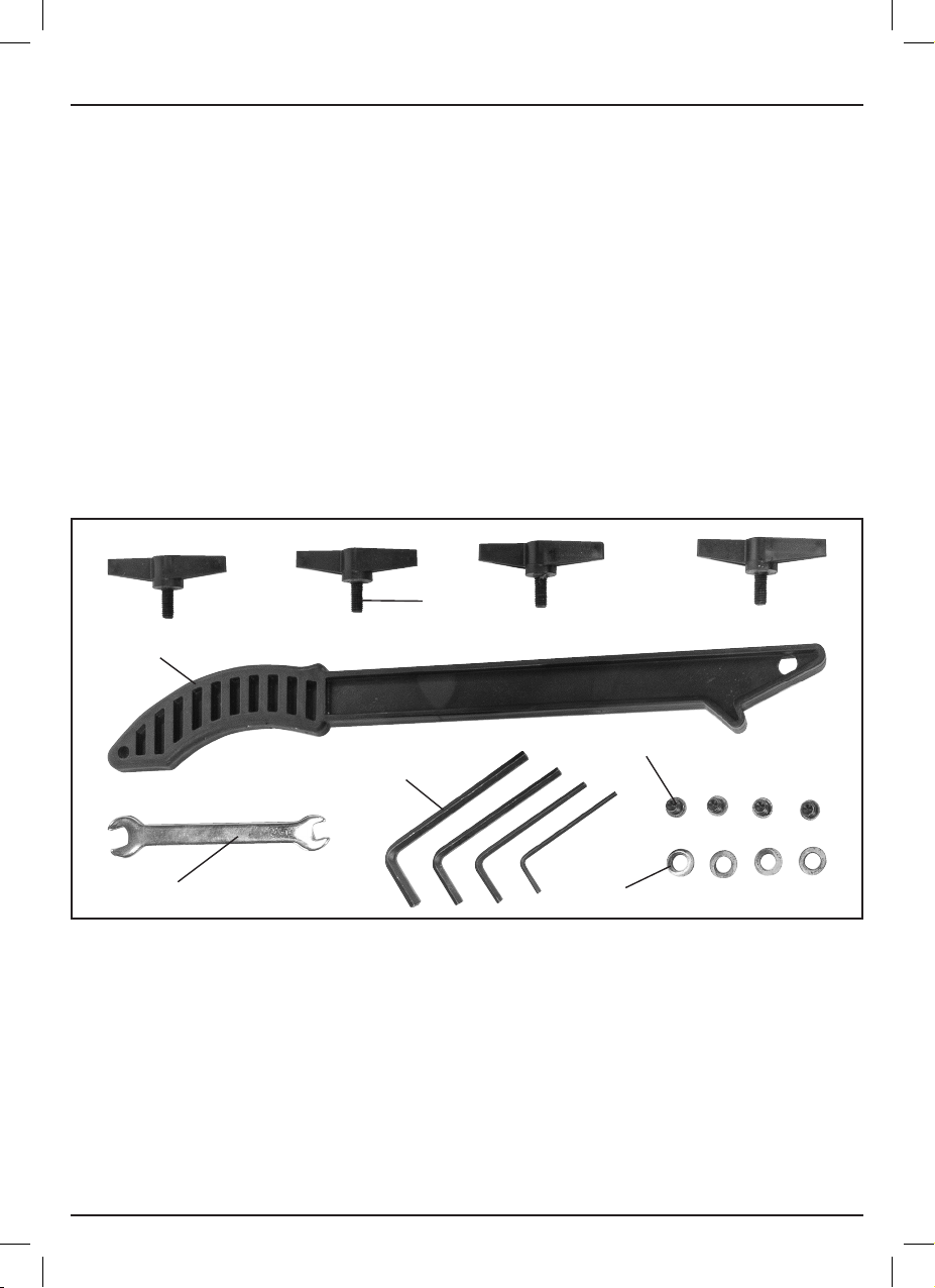
7.2 WHAT’S IN THE BOX
As well as the bandsaw, there are several parts not fitted or attached to it.
Note: For details of our full range of accessories and consumables, please visit drapertools.com
(31)
(32)
(33)
(31) 4 x plastic wing bolts
(32) Push stick
(33) Open-ended spanner
(34) 4 x Hex. keys
(35) 4 x M7x12mm pan head screws
(36) 4 x 8.5mm washers
(35)
(34)
(36)
– 12 –
8. PREPARING THE BANDSAW
Note: Remove the plug from the socket before
carrying out adjustment, servicing or maintenance.
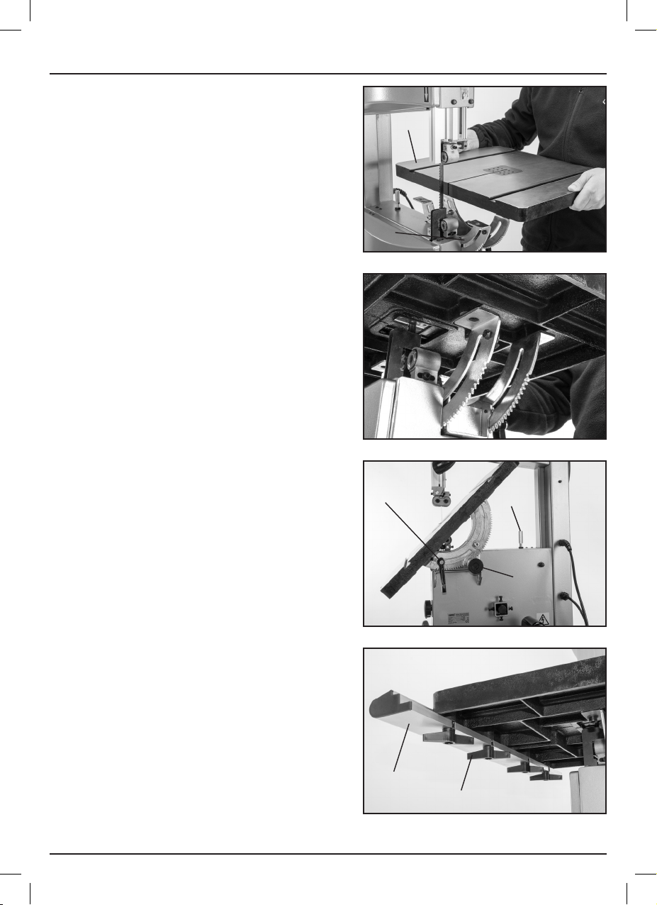
8.1 INSTALLING THE TABLE – FIG. 1
Pull the table (10) onto the cradle/table tilt
adjustment (17) ensure the holes on the underside
are lined up, using the pan head screws (35) and
washers (36) secure the table in place.
(10)
8.2 LEVELLING THE TABLE –
FIGS. 2 – 3
The saw table can be tilted up to 45°. To tilt,
loosen the wing nut (17.1) on the cradle. A stop
on the underside of the table rests on the lower
wheel housing (17.3) when the table is at 90°
with the blade.
Loosen the lock nut (17.2) and turn the bolt in
or out, as required, to change angle against the
saw band.
Use a spirit level to check the table is square.
8.3 RIP FENCE RAIL – FIG. 4
Place the rip fence rail (12) on the front edge of
the table and tighten in place with the four plastic
wing bolts (31).
(17)
FIG. 1
FIG. 2
(17.1)
FIG. 3
(17.3)
(17.2)
– 13 –
(12)
(31)
FIG. 4
8. PREPARING THE BANDSAW
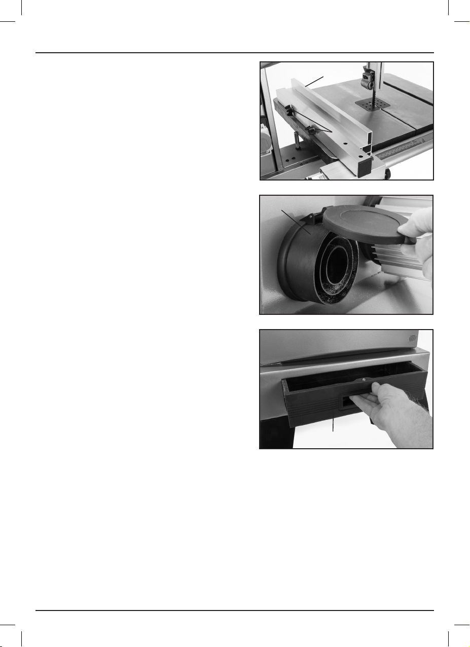
8.4 RIP FENCE – FIG. 5
Attach the rip fence (11) to the rip fence rail as
shown to secure the fence.
When the rip fence is against the blade in its
vertical configuration ensure the scale reads ‘0’
through the window. If not loosen wing bolts (31)
and adjust accordingly.
The rip fence can be set up for left and right
handed cuts and the wing nuts (11.1) can be
loosened to change the rip fence into a horizontal
configuration for thin cuts.
8.5 DUST EXTRACTION OUTLET –
FIG. 6
Note: Inhalation of dust particles can be
detrimental to your health. The dust outlet (20)
must be connected with a dust extraction machine.
Note: Due to the outlet diameter, a size adaptation
may be necessary. All wood dust [including dust
from composites like chipboards and fibre boards
etc.] is hazardous to health; it can affect the nose,
the respiratory system and the skin for example
MDF [medium density fibreboard] which can
contain formaldehyde [a known carcinogen].
In addition to the above measures a correctly fitted
dust mask, suitable for the activity and in
accordance to the relevant standard, must be
worn. For work activities involving exposure to fine
wood dust a mask rated to at least FFP2 should
be used.
(11)
(11.1)
FIG. 5
(20)
FIG. 6
8.6 DUST TRAY – FIG. 7
Insert the dust tray (27) into the slot in the base of
the saw.
– 14 –
(27)
FIG. 7

9. OPERATING THE BANDSAW
Note: Removing the plug from the socket before
carrying out adjustment, servicing or maintenance.
9.1 NO-VOLT ON/OFF SWITCH –
FIG. 8
The bandsaw is fitted with a no-volt switch (13).
To switch the bandsaw on, push the green button
marked ‘I’.
To switch the bandsaw off, push the red button
marked ‘0’.
In the event of a power failure the bandsaw will
have to be manually re-started.
9.2 LED WORKLIGHT – FIG. 9
The flexible light is switched on by depressing the
switch (26.1).
FIG. 8
(13)
9.3 TILTING THE TABLE – FIG. 10
Using the bevel indicator (17.4) as a guide the
angle of the table can be adjusted between 0°
and 45°.
To tilt, loosen the wing nut (17.1) and adjust by
turning (17.2) when set, secure.
Note: When greater accuracy is required,
make practice cuts on waste material and
adjust the table as necessary.
(26.1)
FIG. 9
(17.4)
(17.1)
(17.2)
FIG. 10
– 15 –

9. OPERATING THE BANDSAW
9.4 UPPER AND LOWER DOORS –
FIG. 11
To open doors turn the door locks (24) and
(25) clockwise to close push door shut and turn
locks anticlockwise.
Warning!
The bandsaw is fitted with a micro switches inside
the doors. This safety feature will de-activate the
machine when the doors are open.
(24)
9.5 BLADE GUARD SLIDE
ADJUSTMENT – FIG. 12
The blade guard (7) should be adjusted to within
3mm of the workpiece. Always adjust the blade
guide assembly to suit the workpiece before each
operation. Loosen the blade guard adjustment (6)
to raise or lower the guard. When complete, tighten
to secure.
FIG. 11
(21)
(6)
(7)
FIG. 12
– 16 –

9.6 TENSIONING THE BLADE –
FIGS. 13 – 14
The blade tension lever (28) allows the quick
release of the blade tension when changing
the blade.
To set the tension the lever should be moved
anti-clockwise to the tensioned position as shown.
Turning the fine tensioner setting knob (3)
clockwise will increase the tension, turning
anti-clockwise will lower the tension.
Note: Do not overtighten the blade. Too much
tension may cause blade breakage. Too little
tension may cause the blade to slip on the wheels.
To help in the correct tension setting the indicator
(that can be viewed through the blade tension
viewing window (5)) should be set to the correct
blade width that is being used.
9.7 CHANGING AND SETTING THE
NEW BLADE – FIGS. 15 – 16
To change the saw band, remove the rip fence
rail from the table. Slacken the blade tension with
the tensioner, open both doors and remove the
blade carefully.
Fit the new saw band carefully [with the teeth
facing down]. When the saw band is located
correctly through the guide and is sat centrally
on the upper and lower wheels, operate the
tensioner to re engage the tension. As the tension
has been released during this process, the tracking
should be checked and adjusted as per page 18.
The blade should run in the centre of the rubber
lined bandsaw wheels otherwise it may jump off.
Warning!
Select a blade suitable for the intended
material and use on this machine. Read the
safety instructions.
(3)
(28)
FIG. 13
(5)
FIG. 14
FIG. 15
– 17 –
FIG. 16

9. OPERATING THE BANDSAW
9.8 TRACKING THE BLADE –
FIGS. 17 – 18
Note: The blade tension must be correctly adjusted
before tracking the blade.
When fitting a new blade it may be necessary for
the blade tracking to be adjusted.
The blade should sit centrally or slightly to the front
of the rubber on the two wheels. To track the blade,
open the top & bottom doors, move the blade by
hand by rotating the upper saw band wheel (4).
If the blade starts moving towards the front edge
of the wheel, turn the saw band tracking knob (16)
clockwise.
There is a large wing nut (16.1) found behind the
tracking adjustment knob to lock the position
once set.
9.9 ADJUSTING THE UPPER BLADE
GUIDE ASSEMBLY – FIGS. 19 – 20
Loosen the hex screw (8.1) and adjust the guide
assembly forward or backwards so that the front of
the bearing is 2mm back from the deepest part of
the tooth.
Loosen the left hand nut (8.2) to adjust the rear
thrust bearing so that it is 0.5mm from the back
edge of the blade.
For thicker blades fine adjustments can be
achieved by using the hex key provided (34)
(not pictured) to loosen the bolt (8.3) behind
each of the side bearings.
Slide them left or right in the slot so that they are
0.5mm from the side of the blade.
FIG. 17
FIG. 18
(16)
(8.2)
(4)
(16.1)
(8.1)
– 18 –
FIG. 19
(8.3)
FIG. 20

9.10 IF REQUIRED TO ADJUST THE
LOWER BLADE GUIDES – FIG. 21
Use the hex key provided (34) to loosen the left
hand bolt (23.1) allowing the guide assembly to
move forwards or backwards so that the front edge
of the bearing is 2mm back from the deepest part
of the blade teeth.
Loosen the right hand bolt (23.2) to adjust the rear
thrust bearing so that it is 0.5mm from the back
edge of the blade.
Warning!
Do not start the bandsaw until all blade guides
have been correctly adjusted and all locking
screws and bolts are secured.
Note: Always reset the upper and lower blade
guides after changing to a different width of blade.
9.11 MITRE GUIDE – FIG. 22
Slide the mitre guide (21) into one of the T-slots on
the table (10). Loosening the handle (21.1) will
enable you to adjust the angle. There are stops for
90° and 45° each way. Pull out the silver pin at the
front of the mitre guide to move past the stop.
Ensure the handle is fully tightened before using
the guide.
9.12 SETTING THE BLADE SPEED –
FIGS. 23 – 24
To change the speed of the bandsaw, open the
lower door and turn the drive belt tensioning knob
(30) anticlockwise to slacken the drive belt.
Move the belt (15) over to the other pair of pulleys.
Re-tension the belt so that finger pressure deflects
it by approx. 10mm.
There are two speeds 800m/min for general
woodcutting, 370m/min for cutting hardwoods
and metals.
(23.1)
FIG. 21
FIG. 22
FIG. 23
(23.2)
(21.1)
(21)
(10)
(30)
– 19 –
(15)
FIG. 24

10. TIPS ON USING YOUR BANDSAW
10.1 USEFUL TIPS
For all cutting operations the upper blade guard should be adjusted to just clear the work being
cut (3mm). Not only does this provide the best operator safety, but it also brings the blade guides
closer to the work giving more accurate results and easier control.
Use both hands to feed the workpiece to the blade. The work must be held flat on the table at
all times to prevent binding of the blade. Use a steady even pressure just sufficient to keep the
blade cutting.
Always use a rip fence or mitre guide where possible to eliminate any sideways slip of the work.
This is most important when the table is tilted to an angle.
Always plan work ahead. The tradesman’s rule is “measure twice, cut once”. It is best to finish a
cut in one continuous operation, but frequently backtracking will be necessary. Turn off the motor
and allow the blade to come to a complete stop before backing the blade out of the cut.
Remember that the blade removes material during the cut. This gap created by the blade is called
the kerf and must be allowed for when cutting to exact sizes. Plan your cut so that the kerf is to the
scrap side of the line you wish to cut. If necessary, allow a little more for finish sanding.
Rip sawing
This term refers to the cutting of timber with the grain rather than at a right angle to the grain.
You can rip wood freehand to a previously drawn line, but best results are obtained by using the
rip fence. If the table is set at a level angle set the rip fence to the left hand side of the blade.
This allows you to use your right hand to hold the work firmly against the fence. The width of cut
indicator on right hand side of the blade if the width of the workpiece allows it.
With the fence on the downhill side of the table it will help support the work against slipping.
The width cut indicator shows the distance between the blade and the rip fence.
When cutting long pieces, consider making cuts from the waste edge up to the cut line, then the
waste will fall away in small sections as you make the cut. The workpiece may need additional
support to stop it from bending and causing the blade to bind, this can be achieved with a table at
the correct height or an assistant, provided that they have been trained in the use of the machine
and are aware of all safety implications.
Cross cutting
This term refers to cutting of timber at right angles to the grain. This type of cut can also be made
freehand but the mitre guide is used to ensure accurate results. The mitre guide can be adjusted
to a 45˚ angle to produce mitre cuts, or with the table tilted as well, compound mitre cuts.
Make sure the work is held firmly against the table and against the face of the mitre guide.
Be careful to keep your fingers away from the blade, particularly at the end of the cut.
Freehand sawing
The ease with which many different and varied shapes can be cut is one of the most important
features of the bandsaw. Select a blade suitable for cutting the smallest radius in the work you
have planned.
When freehand cutting always feed the work slowly so that the blade can follow the line you wish
to saw. Make sure not to drag the work off line forcing the blade sideways, or twisting it.
In many cases, it is helpful to rough cut about 6mm away from the line in difficult curves and
corners. In the case of very sharp curves which may be too tight for the blade, make relief cuts
onto the face of the curve so that these scraps will fall as the final radius is sawn.
– 20 –

11. TROUBLESHOOTING
11.1 TROUBLESHOOTING GUIDE
Warning!
For your own safety, turn the switch off and remove the plug from the power supply socket.
Problem Possible Cause Remedy
Breaking blades. Wrong tension.
Over working blade.
Wrong blade application.
Twisting blade.
Motor will not run. Defective cable or plug.
Defective motor.
Vibration.
Note: There will always be
some vibration when the saw
is running due to the motor
operation.
Blade runout. Blade guides not aligned. Check blade guide settings
Incorrect mounting of saw.
Unsuitable mounting surface.
Loose table.
Loose motor mounting.
Adjust blade tension.
Reduce feed rate.
Use narrow blades for cutting
thin material or sharp curves,
wide blades for thicker
material or straight cuts.
Avoid side pressure on blade
Replace defective parts.
Consult your service agent.
Any attempt to repair this
motor may be dangerous
unless the repair is carried
out by a qualified service
agent.
Refer to the mounting
instructions in this manual.
The heavier your work
bench is, the less vibration.
A plywood workbench is not
as good as solid timber.
Tighten table locking knob.
Adjust table if necessary.
Tighten mounting screws.
as per manual.
Note: Repairs should only be carried out by a qualified person.
– 21 –

12. MAINTENANCE
12.1 SLIDE ADJUSTMENT
Warning!
For your own safety turn switch off and remove plug from power supply before attempting any
adjustment or repairs.
Changing tyres
Eventually the rubber tyres on the bandsaw wheels will wear due to the constant contact of the
sharp teeth of the blade. Lift the edge of the tyre with a small screwdriver and the tyre can be
worked off the wheel easily. We recommend that the two tyres be changed at the same time.
(See Spare Parts Listing/Drawing).
Blade guides
Blade guides should be inspected regularly for wear or chipping. When replacing guides replace
all guides at the same time, both upper and lower. (See Spare Parts Listing/Drawing).
Bearings
All bearings used in the construction of your bandsaw and its motor are sealed and lubricated
for life.
Clean out
Remove the plug from the socket before carrying out adjustment, servicing or maintenance.
Accumulated dust and chips should be removed from inside the bandsaw frequently. Open the
front covers and use a brush or vacuum cleaner. At the end of every work session clean sawdust
away from the motor vents.
Regular inspection and cleaning reduces the necessity for maintenance operations and will keep
your tools in good working condition.
The motor must be correctly ventilated during the tools operation. For this reason avoid blocking
the air inlets.
If the replacement of the supply cord is necessary, this has to be done by the manufacturer or his
agent in order to avoid a safety hazard.
– 22 –

13. EXPLANATION OF SYMBOLS
13.1 EXPLANATION OF SYMBOLS
WEEE – Waste Electrical &
Electronic Equipment.
Do not dispose of Waste Electrical & Electronic
Equipment in with domestic rubbish.
Read the instruction manual.
Wear face mask and safety
glasses.
Keep hands away from blade.
Disable the machine before
attempting to maintain it.
14. DISPOSAL
14.1 DISPOSAL
– At the end of the machine’s working life, or when it can no longer be repaired, ensure that it is
disposed of according to national regulations.
– Contact your local authority for details of collection schemes in your area.
In all circumstances:
• Do not dispose of power tools with domestic waste.
• Do not incinerate.
• Do not dispose of WEEE* as unsorted municipal waste.
* Waste Electrical & Electronic Equipment.
– 23 –

CONTACTS
Draper Tools Limited, Hursley Road,
Chandler’s Ford, Eastleigh, Hampshire. SO53 1YF. U.K.
Help line: (023) 8049 4344
Sales desk: (023) 8049 4333
Internet: drapertools.com
E-mail: sales@drapertools.com
General enquiries: (023) 8026 6355
Service/Warranty Repair Agent:
For aftersales servicing or warranty repairs, please contact the
Draper Tools help line for details of an agent in your local area.
YOUR DRAPER STOCKIST
TAFW0821
©Published by Draper Tools Limited.
No part of this publication may be reproduced, stored in a retrieval system or transmitted in any form or by any means,
electronic, mechanical photocopying, recording or otherwise without prior permission in writing from Draper Tools Ltd.
 Loading...