


POCKET
DIGITAL MULTIMETER
52320
IMPORTANT: Please read these instructions carefully to ensure the safe and effective use of this product and save
these instructions for future reference. This manual has been compiled by Draper Tools and is an integrated part of the
product with which it is enclosed and should be kept with it for future references.
This manual describes the purpose for which the product has been designed and contains all the necessary information
to ensure its correct and safe use. We recommend that this manual is read before any operation or, before performing
any kind of adjustment to the product and prior to any maintenance tasks. By following all the general safety
instructions contained in this manual, it will ensure both product and operator safety, together with longer life of the
product itself.
All photographs and drawings in this manual are supplied by Draper Tools to help illustrate the operation of the product.
Whilst every effort has been made to ensure accuracy of information contained in this manual, the Draper Tools policy
of continuous improvement determines the right to make modifications without prior warning.

1. TITLE PAGE
1.1 INTRODUCTION:
USER MANUAL FOR:
POCKET ANALOGUE MULTIMETER
Stock no. 52320.
Part no. DMM7.
1.2 REVISIONS:
Date first published March 2017
As our user manuals are continually updated, users should make sure that they use the
very latest version.
Downloads are available from: http://www.drapertools.com/manuals
DRAPER TOOLS LIMITED WEBSITE: drapertools.com
HURSLEY ROAD PRODUCT HELPLINE: +44 (0) 23 8049 4344
CHANDLER’S FORD GENERAL FAX: +44 (0) 23 8026 0784
EASTLEIGH
HAMPSHIRE
SO53 1YF
UK
1.3 UNDERSTANDING THIS MANUALS SAFETY CONTENT:
WARNING! Information that draws attention to the risk of injury or death.
CAUTION! Information that draws attention to the risk of damage to the product or
surroundings.
1.4 COPYRIGHT © NOTICE:
Copyright © Draper Tools Limited.
Permission is granted to reproduce this publication for personal & educational use only.
Commercial copying, redistribution, hiring or lending is prohibited.
No part of this publication may be stored in a retrieval system or transmitted in any other
form or means without written permission from Draper Tools Limited.
In all cases this copyright notice must remain intact.
2

2. CONTENTS
2.1 CONTENTS
Page content
1 TITLE PAGE
1.1 INTRODUCTION ................................................................................................ 2
1.2 REVISION HISTORY..........................................................................................2
1.3 UNDERSTANDING THIS MANUAL ................................................................... 2
1.4 COPYRIGHT NOTICE ........................................................................................ 2
2 CONTENTS
2.1 CONTENTS ........................................................................................................ 3
3 GUARANTEE
3.1 GUARANTEE...................................................................................................... 4
4 INTRODUCTION
4.1 SCOPE................................................................................................................ 5
4.2 SPECIFICATION................................................................................................. 5
5 HEALTH & SAFETY INFORMATION
5.1 SAFETY PRECAUTIONS ................................................................................... 6
6 IDENTIFICATION............................................................................................................. 7
7 UNPACKING & CHECKING
7.1 PACKAGING....................................................................................................... 8
7.2 HANDLING & STORAGE.................................................................................... 8
8 OPERATING INSTRUCTIONS
8.1 DC VOLTAGE MEASUREMENT ........................................................................ 9
8.2 AC VOLTAGE MEASUREMENT ........................................................................ 9
8.3 DC CURRENT MEASUREMENT .......................................................................9
9 EXPLANATION OF SYMBOLS
9.1 EXPLANATION OF SYMBOLS......................................................................... 10
10 DISPOSAL
10.1 DISPOSAL ....................................................................................................... 11
DECLARATION OF CONFORMITY............................................................................ ENCLOSED
.............................................................................. Page
3

3. GUARANTEE
3.1 GUARANTEE
Draper tools have been carefully tested and inspected before shipment and are guaranteed to
be free from defective materials and workmanship.
Should the tool develop a fault, please return the complete tool to your nearest distributor
or contact Draper Tools Limited, Chandler's Ford, Eastleigh, Hampshire, SO53 1YF.
England.
Telephone Sales Desk: (023) 8049 4333 or Product Helpline (023) 8049 4344.
A proof of purchase must be provided with the tool.
If upon inspection it is found that the fault occurring is due to defective materials or
workmanship, repairs will be carried out free of charge. This guarantee period covering
parts/labour is 12 months from the date of purchase except where tools are hired out when
the guarantee period is 90 days from the date of purchase. This guarantee does not apply
to normal wear and tear, nor does it cover any damage caused by misuse, careless or
unsafe handling, alterations, accidents, or repairs attempted or made by any personnel
other than the authorised Draper warranty repair agent.
Note: If the tool is found not to be within the terms of warranty, repairs and carriage
charges will be quoted and made accordingly.
This guarantee applies in lieu of any other guarantee expressed or implied and variations
of its terms are not authorised.
Your Draper guarantee is not effective unless you can produce upon request a dated
receipt or invoice to verify your proof of purchase within the guarantee period.
Please note that this guarantee is an additional benefit and does not affect your statutory
rights.
Draper Tools Limited.
4

4. INTRODUCTION
4.1 SCOPE
A device to allow simple measurement of voltage, current and resistance.
4.2 SPECIFICATION
Stock no....................................................................................................................... 52320
Part no........................................................................................................................ DMM7
Dimensions (W x H x D) ............................................................................ 55 x 112 x 40mm
Battery type .............................................................................................1 x 12V (Type 23A)
Weight ..............................................................................................................................70g
Fuse and diode protected.
Warning: To avoid electrical shock remove test leads before opening battery cover. To
prevent risk of fire only use the correct size/type fuse, as fitted.
AC Voltage Input impedance: 450K, Input protection: 500V RMS,
Frequency Range: 40Hz-400Hz.
Range Accuracy
200V ± 2.0% rdg ± 5 dgts
500V
DC Current Overload protection: 200mA/250V fuse.
Range Accuracy
2000A ± 2.0% rdg ± 4 dgts
20mA
200mA
Resistance
Range Accuracy
200 ± 1.5% rdg ± 4 dgts
2000
20k
200k
2000k
DIODE CHECK Test current 1.6mA typical.
Range Accuracy
3.2V DC Typical ~
reading = accuracy of the measurement circuit
digits = accuracy of the analogue to digital conversion
WARNING: Ensure the test leads are fully engaged prior to carrying out any
measurements, to avoid an electric shock.
5

5. HEALTH & SAFETY INFORMATION
5.1 SAFETY PRECAUTIONS
This instrument complies with IEC1010 (International Electrotechnical Commission
promulgated safety standards). Design and production using the pollution level 2 safety
requirements.
Warning
To avoid electrical shock or personal injury.
Please read the safety information and “warnings and precautions” before use.
Warning: When measuring voltage above 30V, current above 10ma, AC power with an
inductive load. Use caution not to touch exposed contacts due to the risk of electric shock,
only use approved probes or clamps.
1. Before measuring, check whether the measurement function switch is in the correct
position, check whether the test probe is connected correctly to avoid electric shock.
2. The meter is only to be used in conjunction with the supplied test leads to comply with
safety standards. If the test leads are broken or damaged, replace the test leads of the
same type or the same electrical specifications.
3. Do not use an unapproved fuse to replace the fuse inside the meter. Only replace with
the same model or the same specifications of the fuse. Before changing, remove the
test leads to ensure that there is no signal input.
4. Do not use unapproved batteries to replace the battery inside the meter. Replace only
with the same model or the same electrical specifications of the battery. Before
changing, remove the test leads to ensure that there is no signal input.
5. During electrical measurements, the body must not be directly in contact with the
earth, use insulating materials to keep your body insulated from the earth.
6. Do not store or use in high temperature, high humidity, flammable, explosive and
strong magnetic field environments.
7. Measurements exceeding the limit values of the instrument may damage the instrument and endanger the safety of the operator.
8. Do not attempt to calibrate or service the instrument.
9. Do not insert the test leads to be inserted into the current terminals to measure the
voltage!
6

6. IDENTIFICATION
Function selector.
Power switch.
L.C.D. screen.
Test probe.
V, mA (Voltage, Resistance,
Amperage) probe Socket.
Common earth probe socket.
7

7. UNPACKING & CHECKING
7.1 PACKAGING
Carefully remove the product from the packaging and examine it for any sign of damage
caused during shipping. Lay the contents out and check them. If any part is damaged or
missing, do not attempt to use the tool and contact the Draper Helpline immediately (see
back page for details).
Retain the packaging material at least during the guarantee period: in case the machine
needs to be returned for repair.
Warning! Some of the packaging materials used may be harmful to children, keep them out
of reach from children.
Disposed of any packagaing correctly and according to local regulations.
7.2 HANDLING & STORAGE
Although this machine is small in size, care must still be taken when handling. Dropping
this machine will have an effect on the accuracy. This machine is not a toy and must be
respected.
The environment will have a negative result on its operation if you are not careful. If the air
is damp, components will rust. If the machine is unprotected from dust and debris;
components will become clogged: And if not cleaned and maintained correctly or regularly
the machine will not perform at its best.
8

8. OPERATING INSTRUCTIONS
WARNINGS: Each time before you use this analyser, inspect the test leads, connectors
and probes for damage, e.g. cracks or breaks in the insulation. Any defective leads should
be replaced immediately. If the value to be measured is not known, set the selector switch
to the highest range and reduce until a satisfactory reading is obtained.
8.1 VOLTAGE MEASUREMENT:
1. Connect the red test lead to the ‘V//mA’ probe socket and the black lead to the ‘com’
probe socket Ensure the leads are correctly plugged in.
2. Position the selector switch to the desired voltage range and switch the meter ‘ON’.
3. Connect the test leads to the circuit to be measured.
4. Turn on the power to the circuit to be measured, the voltage value should appear on the
digital display along with the voltage polarity (if reversed only).
8.2 CURRENT MEASUREMENT - FIG.1
1. Connect the red test lead to the ‘V//mA’
probe socket and the black lead to the
‘com’ probe socket (max 10A).
2. Position the selector switch to the desired
amp range and switch the meter ‘ON’.
3. Open the circuit to be measured, and
connect the test leads in series to bridge
the gap.
4. Turn on the power to the circuit to be
measured, the ‘current’ value should
appear on the digital display.
FIG.1
8.3 RESISTANCE MEASUREMENT:
WARNING: If the resistance to be measured is part of a circuit, turn off and disconnect the
power and discharge all capacitors before measurement
1. Connect the red test lead to the ‘V//mA’ probe socket and the black lead to the ‘com’
probe socket.
2. Position the selector switch to the desired ohm range and switch the meter ‘ON’.
3. Connect the test leads to the circuit to be measured.
4. The resistance value should now appear on the digital display.
9
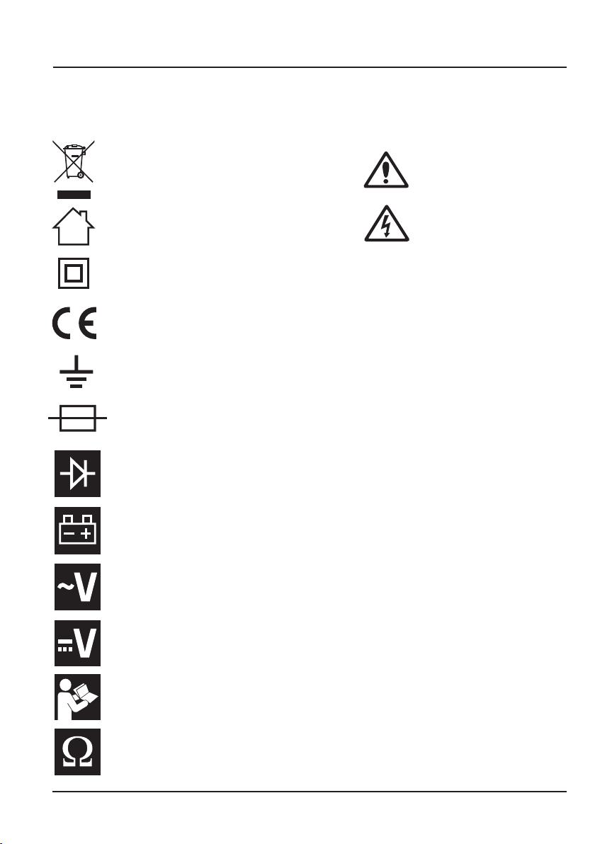
9. EXPLANATION OF SYMBOLS
9.1 EXPLANATION OF SYMBOLS
Carefully remove the product from the packaging and examine it for any sign of damage
WEEE
Do not dispose of Waste Electrical
& Electronic Equipment in with
domestic rubbish
Attention.
For indoor use.
Do not expose to rain.
Class II construction
(Double insulated)
Conforms to all relevant
safety standards.
Earth
Fuse
Diode test
Low battery display
Voltage AC
High voltage / current!
Danger.
10
Voltage DC
Warning!
Read instruction manuals before
operating and servicing this
equipment.
Resistance in Ohms

10. DISPOSAL
10.1 DISPOSAL
- At the end of the machine’s working life, or when it can no longer be repaired, ensure
that it is disposed of according to national regulations.
- Contact your local authority for details of collection schemes in your area.
In all circumstances:
• Do not dispose of power tools with domestic waste.
• Do not incinerate.
• Do not abandon in the environment.
• Do not dispose of WEEE*
as unsorted municipal waste.
* Waste Electrical & Electronic Equipment.
11

CONTACT US
Draper Tools Limited, Hursley Road,
Chandler's Ford, Eastleigh, Hampshire. SO53 1YF. U.K.
Helpline:
Sales Desk:
+
44 (0) 23 8049 4344
+
44 (0) 23 8049 4333
Internet: www.drapertools.com
E-mail: sales@drapertools.com
General Enquiries: (023) 8026 6355
Service/Warranty Repair Agent:
For aftersales servicing or warranty repairs, please contact the
Draper Tools Helpline for details of an agent in your local area.
YOUR DRAPER STOCKIST
©Published by Draper Tools Limited.
No part of this publication may be reproduced, stored in a retrieval system or transmitted in any form or by any means,
electronic, mechanical photocopying, recording or otherwise without prior permission in writing from Draper Tools Ltd.
DBMC0217
 Loading...