

Page 1

HAND HELD
BRAKE PIPE
FLARING TOOL
Version 1 – January 2023
EN
Original Instructions
4.75mm DIN
23313 – BPF/HAND/DIN INSTRUCTIONS FOR USE
Read this manual in full before using this product and retain it for future use. Always use the latest version of the manual.
Please visit drapertools.com/manuals for the latest version.
1. Intended Use
This product is designed to are brake pipes of 4.75mm
according to DIN Convex standards. Any other application
beyond the conditions established for use will be
considered misuse. Draper Tools accepts no responsibility
for improper use of this product.
Important: Ensure that you are familiar with the various
types of ares and their applications before using this
product. ALWAY S consult the vehicle manufacturer’s
instructions before use.
2. What’s in the Box?
Before assembling the product, lay the contents out and
check them against the parts listed below. If any part is
damaged or missing, do not attempt to use the product;
please contact the Draper Helpline.
A. 1 × Flaring tool
A1. Die
A2. Locking screws
B. 1 × Double-ended punch
B1. 4.75mm DIN punch
B2. Stop punch
C. 1 × Punch grease
(A1)
(A)
3. Operating Instructions
1. Partly screw the stop punch (B2) into the aring tool so
that the nut is no more than 5mm from the die (A1).
(A1)
(B2)
1 Fig.
2. Ensure that the tube nut is installed onto the brake pipe,
then insert the brake pipe into the open end of the die
and hand-tighten the locking screws (A2) just enough to
grip the pipe.
(A2)
(A2)
(C)
(B2)
(B)
(B1)
Helpline: +44 (0) 23 8049 4344 Sales Desk: +44 (0) 23 8049 4333 General Enquiries: +44 (0) 23 8026 6355 Website: drapertools.com Email: sales@drapertools.com
Draper Tools Limited, Hursley Road, Chandler’s Ford, Eastleigh, Hampshire, SO53 1YF, UK 0123
2 Fig.
Important: DO NOT overtighten the locking screws at
this stage as the stop punch may damage the pipe.
Page 2
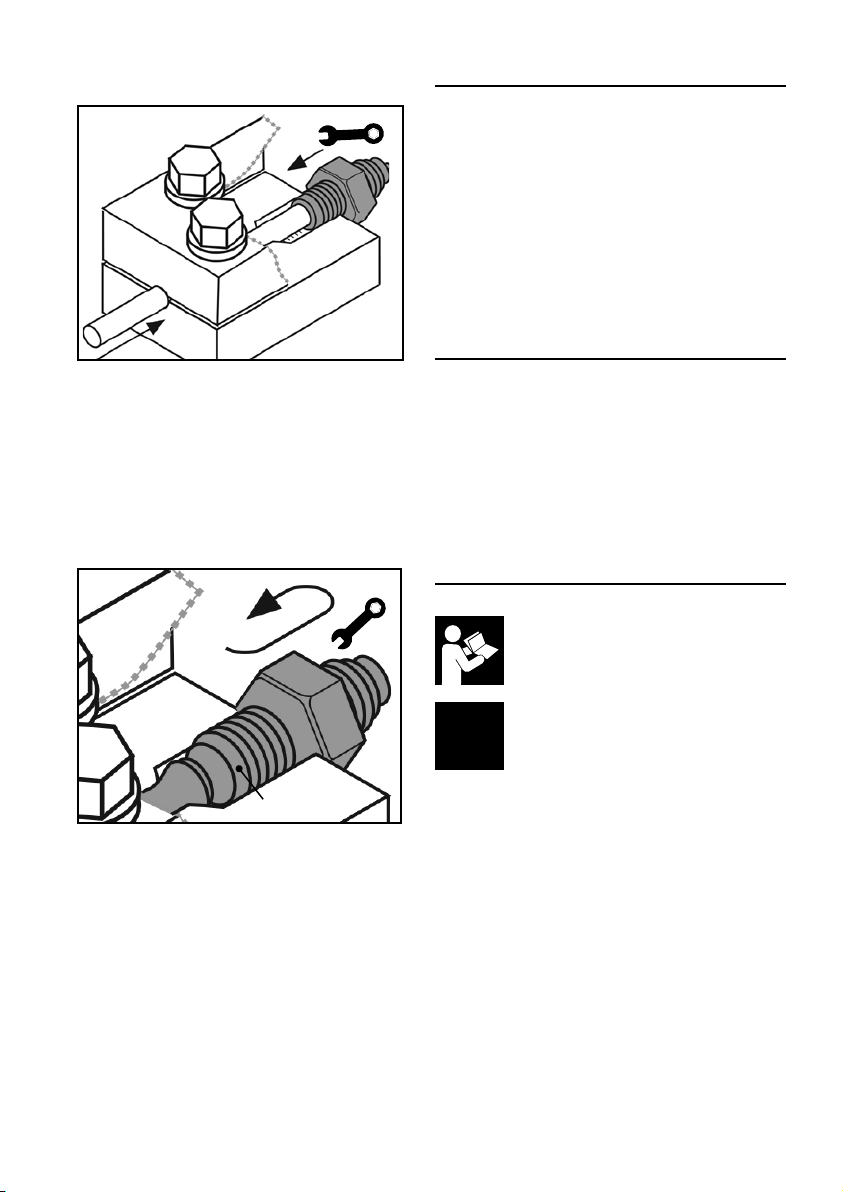
3. Use a 16mm spanner (not supplied) to screw the stop
punch fully into the die until tight.
3 Fig.
4. Use a 10mm spanner (not supplied) to fully tighten the
locking screws and secure the pipe.
Important: If the locking screws are not suciently
tight, the pipe will move during the aring process and
damage the are.
5. Unscrew the stop punch from the die.
6. Fully screw the 4.75mm DIN punch (B1) into the die until
it is tight.
4. Preparing the Brake Pipe
Important: A LWAYS ensure that the brake pipe is correctly
prepared before aring.
• The end of the pipe MUST be cut square.
• The outside edge of the pipe must be champfered by
approximately 0.25mm at 45°.
• The bore of the pipe must be deburred.
• If the pipe is plastic-coated, remove at least 6mm from
the end of the pipe to be ared, ensuring that the pipe is
not scored and that no metal is removed while doing so.
Important: DO NOT use an abrasive cloth on the end of the
brake pipe to be ared.
5. Maintenance and Storage
• Clean the product of dust or debris before and after
each use.
• Replace any punch that shows sign of damage or
excessive wear.
• Before storing the product, wipe it thoroughly with a
lightly oiled cloth to prevent corrosion of the exposed
metal parts.
• Store the product in a clean and dry environment, out of
reach of children.
6. Explanation of Symbols
(B1)
4 Fig.
7. Remove the punch from the die, then loosen the locking
screws and remove the pipe from the tool.
4.75mm
DIN
Read the instruction manual
Flaring output size
 Loading...