

Page 1
SmartTrim
(UNI-0005 / UNI-0007)
Overview
®
for UniSee
®
500/700
INSTRUCTIONS
INSTALL ATI O N & OPERATION
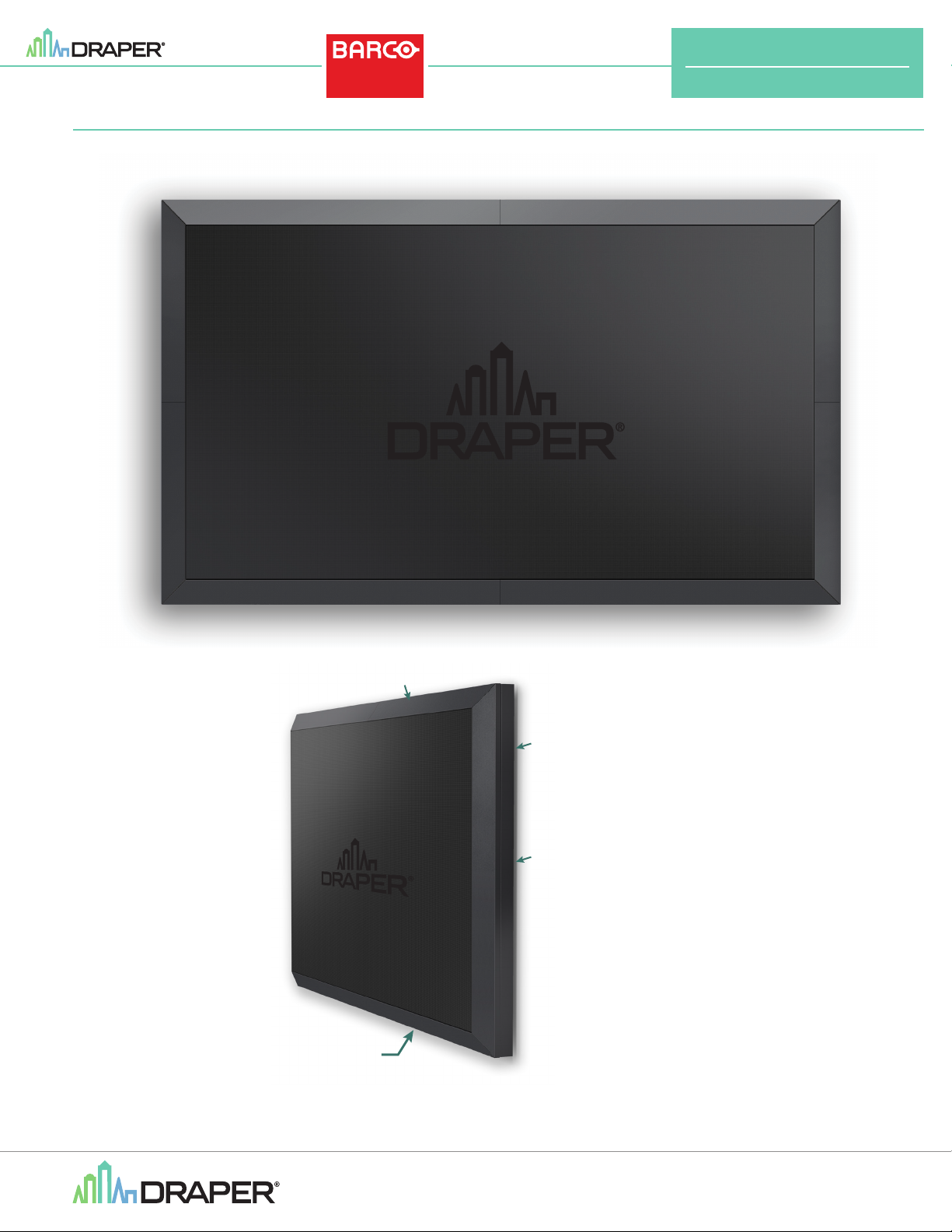
TRIM FACE
VENTED
FLANGE
TRIM
FLANGE
MOUNTED TO WALL:
Approx. 0.25" (6.35mm)
gap between flange
and wall typical
If you have any difficulties installing or ser vicing your
SmartTrim, call your dealer or Draper, Inc.
Draper, Inc. | 411 S. Pearl St. Spiceland, IN 47385
draperinc.com | 765.987.7999 | 800.238.7999
© 2021 All Rights Reserved | FORM: SmartTrim_BarcoUnisee_500_700_Inst21
Page 2
SmartTrim
®
for UniSee
®
500/700
(UNI-0005 / UNI-0007)
Important Safety Information
WARNING
Improper installation and use of Smar tTrim can result in serious injury or death. Primarily, injuries can occur when the SmartTrim falls due to imprecise
installation, mishandling of the SmartTrim during installation or installation on an insufficient wall or ceiling structure. Please use extreme care.
1.
Please read the following installation guidelines thoroughly and follow them carefully. Failure to do so may cause product to fall or otherwise fail, and could result in
serious injury.
2.
Installation and calibration of the SmartTrim should only be performed by an authorized, qualified, and experienced professional. In particular, electrical work and
wiring [indicated in diagram by dashed lines] must be completed only by a qualified professional electrician who has read this manual completely and is familiar with
the construction and operation of this equipment and the hazards involved.
3.
Turn off power and any nearby equipment or cables carrying electricity before connecting switches, wires, controls, or electrical components.
4.
Do not affix the unit to wall or ceilings that have inadequate strength to permanently hold the unit during use. It is the owner’s and installer’s responsibility to confirm
the wall to which the unit attaches is sufficient to permanently hold the weight and stress loads of the unit at all times. Draper, Inc., is not responsible for improper
installation, application, testing or workmanship related to the product at place of installation.
5.
It is the installer’s responsibility to make sure appropriate fasteners are used for mounting.
6.
All brackets and other hardware must be installed level. SmartTrim must be level and square.
7.
Never leave the area while operating the SmartTrim during installation, maintenance, or normal operation, unless it is secure and safe.
8.
Before testing or operation, carefully inspect the entire area and areas underneath to be sure no persons or objects are in the area.
9.
During testing or operation, carefully watch the surrounding area for any potential safety concerns including nearby persons or objects.
10.
After installation, the entire system should be carefully tested to ensure safe and normal operation.
Extreme care should be taken during testing to remain clear of moving parts to avoid possible injury.
11.
Installation and maintenance of Smar tTrim should be performed only by authorized and qualified personnel, who have been trained in the safe and effective
operation of the SmartTrim & understand its safety features.
12.
The safety features of the SmartTrim should never be disabled, bypassed or overridden.
The system should not be operated until all safety features are properly and completely installed, calibrated and tested.
13.
SmartTrim may need to comply with local, state or district rules and regulations, in particular when installed in schools.
All applicable rules and regulations should be reviewed before installation and use.
14.
Failure to precisely follow installation guidelines invalidates all warranties.
15.
Custom products/installations may not be reflected in this manual.
Call Draper, Inc., if you have questions about the installation of custom products or any questions about your installation.
Before Beginning Installation
1.
Look for any job site conditions that could interfere with installation or operation of the system.
2.
Read carefully and be sure to understand all installation instructions and all related operations manuals. These instructions are intended to as a guide for the
installer and owner. They should be followed closely and combined with the expertise of experienced qualified installers. Draper, Inc., is not responsible for
improper installation, application, testing or workmanship related to the product at place of installation. Please retain all instructions for future use.
3.
Open cartons lengthwise.
4.
Locate and lay out all pieces.
5.
Inspect all boxes to make sure you have received the proper SmartTrim and parts.
6.
If you have any difficulties with installing, servicing or operating your SmartTrim, call your dealer or Draper, Inc., 765 987-7999.
Section 1 - Personnel and Tools Required
PERSONNEL REQUIRED TOOLS REQUIRED
OR
Barco UniSee
Service Tool
No. 5 HEX WRENCH
10mm, 15mm &
17mm WRENCHES
Page 3
SmartTrim
CC287.294SA CC287.295SA CC287.296SA
(UNI-0005 / UNI-0007)
®
for UniSee
®
500/700
page 3 of 7
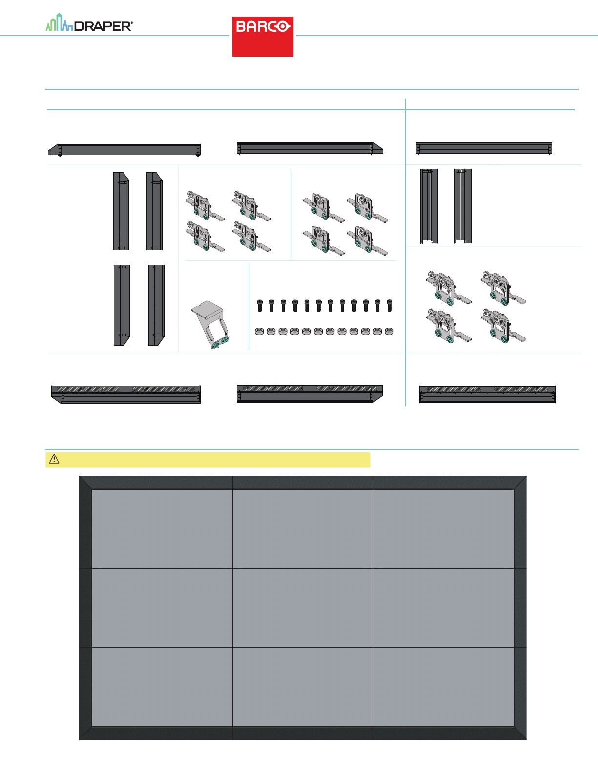
Section 2 - SmartTrim Components List
Standard Parts for all installations For installations larger than 2 x 2
Top Left Trim - (1x)
CC287.291SA
Corner
Vertical
Trim A - (2x)
CC287.296SA
Corner
Vertical
Trim B - (2x)
CC287.294SA
Bottom Left Trim - (1x)
CC287.410SA
Top Right Trim - (1x)
CC287.293SA
Corner Trim Brackets - (4x)
C002.1553SA
Bracket
Alignment
Tool - (1x)
C002.1555SA
Bracket Fasteners [M6x20] - (12x)
Bracket Washers - (12x)
Bottom Right Trim - (1x)
CC287.408SA
Corner Trim Brackets - (4x)
C002.1552SA
Top Horizontal Trim - (varies)
CC287.292SA
Middle
Vertical
Trim -
CC287.295SA
Edge Trim Brackets -
C002.1554SA
(varies)
(varies)
Bottom Horizontal Trim - (varies)
CC287.409SA
Section 3 - SmartTrim Panel Map
Caution: UniSee LCD Display wall must be properly assembled, aligned on all axes and level.
CC287.291SA
Figure 1
CC287.293SACC287.292SA
CC287.294SA CC287.295SA CC287.296SA
CC287.409SACC287.410SA
CC287.409SA
Page 4
SmartTrim
Service Tool
(UNI-0005 / UNI-0007)
®
for UniSee
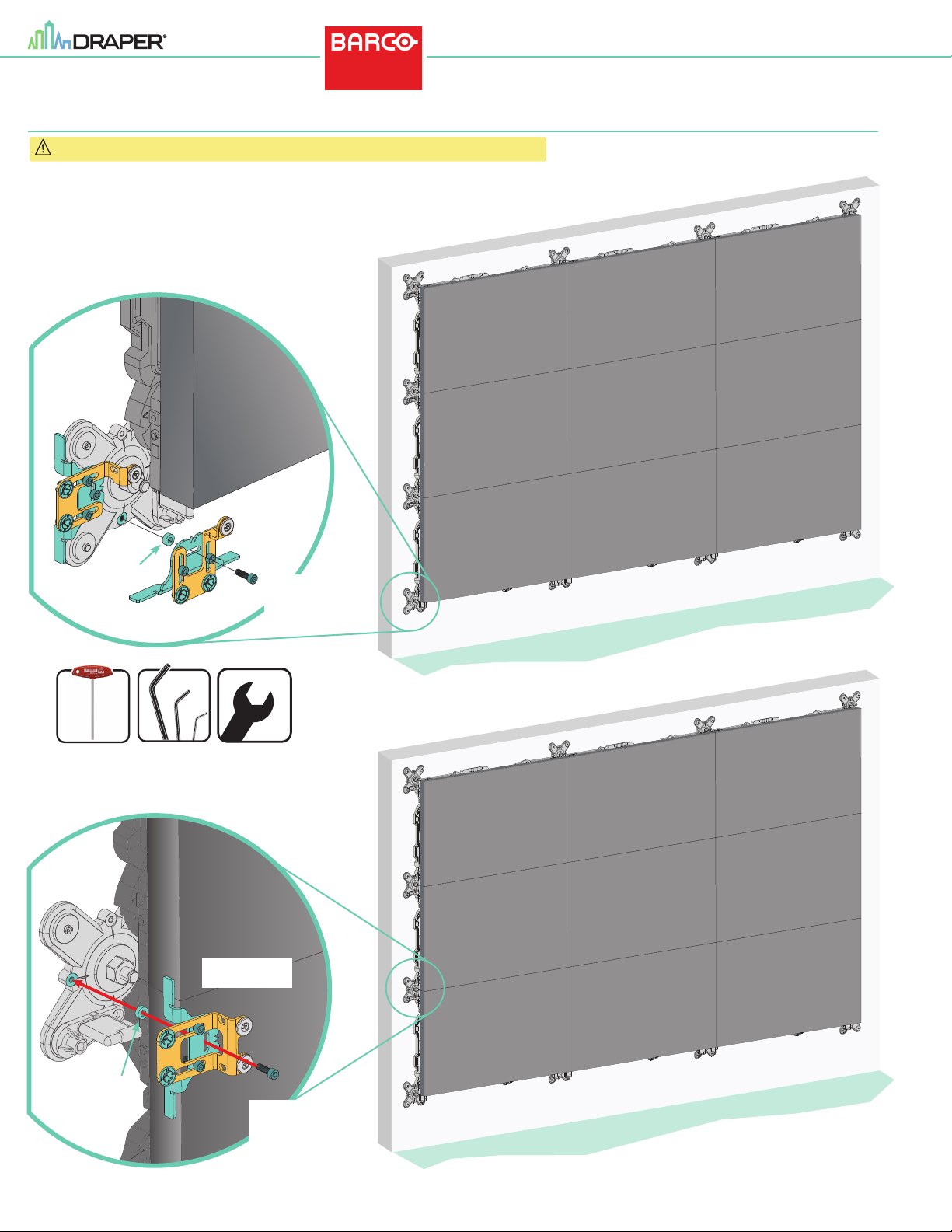
Section 4 - Attaching SmartTrim Brackets to Barco UniSee
Caution: UniSee LCD Display wall must be properly assembled, aligned on all axes and level.
1
Corner Mou nting Bracket
C002.1553SA
(Shown In stalled)
BARCO
UNISEE
®
500/700
page 4 of 7
Washer
Barco UniSee
OR
No. 5 HEX WRENCH
LCD PANEL
Corner Mou nting Bracket
C002.1552SA
Use Barco UniSee
Service Tool
or 5mm Hex
10mm, 15mm &
17mm WRENCHES
Figure 2
2
Washer
Edge Moun ting Bracket
C002.1554SA
Figure 3
Use Barco UniSee
Service Tool
or 5mm Hex
Page 5
SmartTrim
(UNI-0005 / UNI-0007)
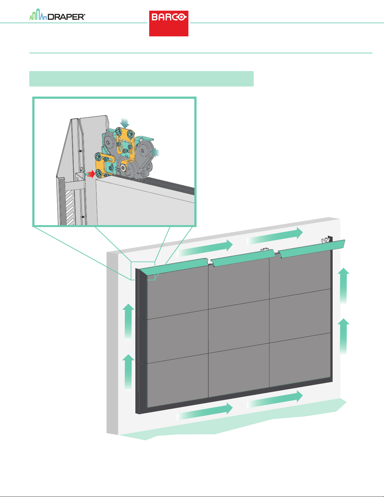
Section 5 - Attaching SmartTrim section to SmartTrim Brackets
1.
Insert the two (2) guide pins on the SmartTrim section into the receivers on the adjustable mounting brackets.
SmartTrim will snap into place against the side of the LCD panels.
Please Note: If there are any gaps between the SmartTrim and the LCD panels, or SmartTrim section will
SmartTrim
Section
not fit, refer to Section 6 - Adjusting SmartTrim Brackets on page 6.
6
®
for UniSee
Adjustable
Brackets
Barco Unisee
X-Bracket
®
500/700
page 5 of 7
Figure 4
L C D
P a n e l
12
11
10
9
6
8
5
7
4
3
2
1
Page 6
SmartTrim
(UNI-0005 / UNI-0007)
Section 6 - Adjusting SmartTrim Brackets
®
for UniSee
®
500/700
page 6 of 7
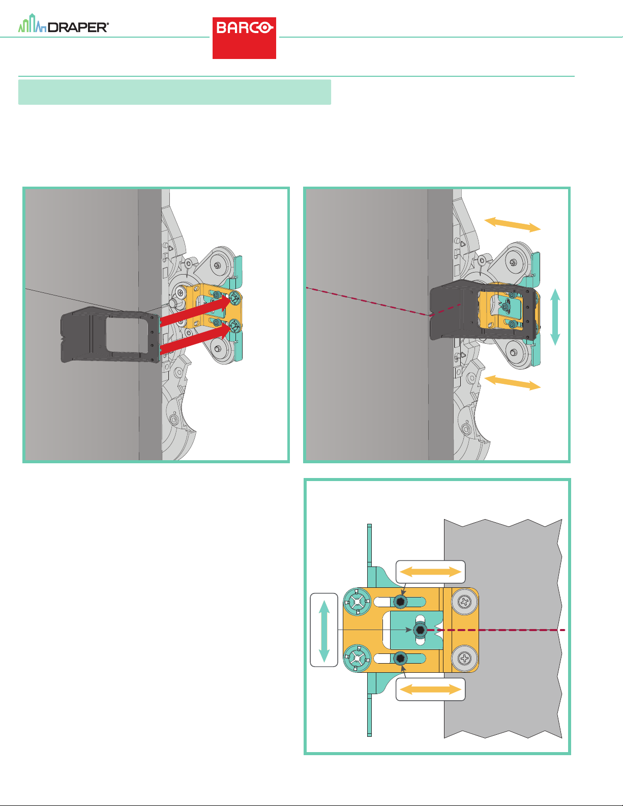
Please Note: Figures 5-A thru 5-C below show an edge bracket on the side of the Unisee.
SmartTrim Adjustable Bracket is always aligned with the vertical center of the UniSee Wall Cross.
During installation of the Unisee Video Wall, the position of the LCD seam may have moved in relation to the Wall Cross.
Draper SmartTrim adjustable brackets are designed to move both ver tically and horizontally to ensure realignment with the LCD Panels.
The same procedure shown below should be used on the top and corners.
LCD
Panel
Alignment
Tool
Edge Mounting
Bracket
LCD
Panel
LCD Seam
Aligned with
Bracket Center
LCD
Panel
Figure 5-A
To adjust the SmartTrim Brackets:
1.
Attach the alignment tool to the Smar tTrim Bracket (see Fig. 5-A).
2.
Ensure that the notch aligns with the seam of the LCD panel (see Fig. 5-B).
If the notch does not align with the seam, loosen the set screws in the bracket
(see Fig. 5-C) and reposition the bracket until it is aligned (see Fig. 5-B).
3.
Once aligned, retighten set screws.
4.
Repeat until all brackets are aligned with the closest LCD seam.
5.
Install the SmartTrim sections according to Section 5 - Attaching Smar tTrim
sections to Smar tTrim Brackets
LCD
Panel
Figure 5-B
SmartTrim Bracket Adjustments
Loosen
Set Screws
to Adjust
LCD Seam
Aligned with
Bracket Center
Figure 5-C
Page 7
SmartTrim
(UNI-0005 / UNI-0007)
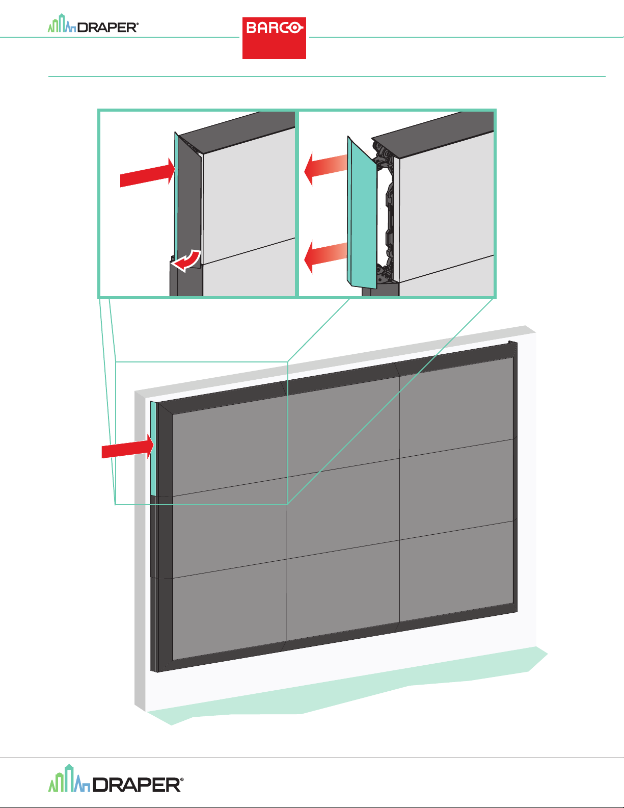
Section 7 - Removing SmartTrim Panels
®
for UniSee
1 2
PRESS
®
500/700
page 7 of 7
PRESS
Figure 6
If you have any difficulties installing or ser vicing your
SmartTrim, call your dealer or Draper, Inc.
Draper, Inc. | 411 S. Pearl St. Spiceland, IN 47385
draperinc.com | 765.987.7999 | 800.238.7999
© 2021 All Rights Reserved | FORM: SmartTrim_BarcoUnisee_500_700_Inst21
Page 8

 Loading...