

Page 1
1
TAPE MEASURE
Premier XL / Targa XL 220V
Electric projection screen
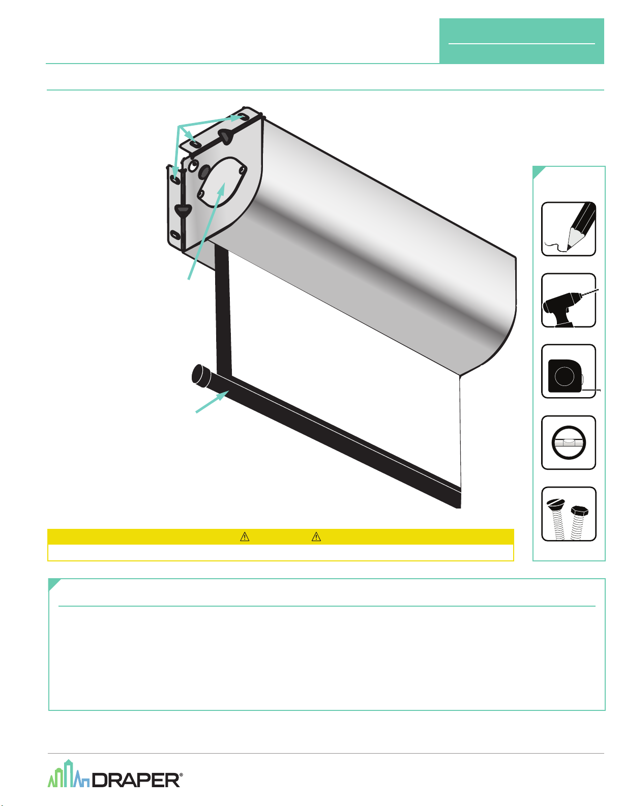
Overview - Components
1.
Mounting holes
2.
Junction box cover
3.
Dowel
4.
Front cover
2
INSTRUCTIONS
INSTAL L AT I ON & OPE R ATI O N
TOOLS
REQUIRED
4
PENCIL
POWER DR ILL
(Targa Pictured)
3
CAUTION
Read and understand all warnings
Contents
Overview - Components .......................................................................................1
Section 1 - Electrical Connections .....................................................................2
PLEASE READ - Safety Information ....................................................................2
Section 2 - Hanging Screen .................................................................................3
Section 3 - Operation............................................................................................3
Section 4 - Tab-Tension Adjustment Procedure ..............................................3
(Page 2 of this document)
LEVEL
HARDWARE
(by others)
before beginning installation.
Section 5 - Limit Adjustments .............................................................................4
Section 6 - Dimensions and Methods of Installation ......................................5
Section 7 - Wiring Diagrams ................................................................................6
Section 8 - Wiring Diagrams ................................................................................7
Section 9 - Accessing Internal Low-Voltage Control Unit
(LVC-IV)
.................8
If you have any difficulties installing or servicing your
Premier XL / Targa XL , call your dealer or Draper, Inc.
Draper, Inc. | 411 S. Pearl St. Spiceland, IN 47385
draperinc.com | 765.987.7999 | 800.238.7999
© 2021 All Rights Reserved | FORM: Premier_XL_TargaXL_220V_Inst20
Page 2
Premier XL / Targa XL 220V
page 2 of 8
Section 1 - Electrical Connections
Screen operates on 220V AC, 50 Hz., 1 ph. current. Screen is shipped with internal
wiring complete and control switch
Wire to connect screen to switch
by installer.
Please Note: Screen must be installed in accordance with requirements of Local
Building Codes, Canadian Electrical Code
Electric Code
(NEC)
, NFPA 70. An appropriate disconnect device shall be provided as
part of building installation.
CAUTION: All operating switches should be "off" before power is connected.
(es)
fully boxed.
(es)
and switch
(es)
to power supply should be furnished
(CEC)
, CAN/CSA C22.1 and National
FOR OPTIONAL PLUG AND PLAY:
Plug-in power cord option available for motor with internal
low-voltage controller. For reconfiguration/conversion of
non-detachable power cord to field wiring for models PRE-28,
PRE-29, TAR-28, and TAR-29 Only:
1.
Disconnect cord plug from outlet.
2.
Remove junction box cover.
3.
Disconnect wire nuts from black, white, and green wires.
4.
Remove power cord and strain relief from screen.
5.
Connect black motor wire to "hot" supply wire.
6.
Connect white motor wire to "neutral" supply wire.
7.
Connect green/yellow wire to "ground" supply wire.
8.
Replace junction box cover.
PLEASE READ - Safety Information
Important Safety Information Important Safety Information
Improper installation and use of the Premier XL / Targa XL screen can result in serious injury or death. Primarily, injuries can occur if the unit falls due to
imprecise installation, mishandling of the unit during installation, or installation on an insufficient wall or ceiling structure. Please use extreme care.
1.
Please read the following installation guidelines thoroughly and follow them
carefully. Failure to do so may cause product to fall or otherwise fail, and could
result in serious injury.
2.
Installation and calibration of the unit should only be per formed by an
authorized, qualified, and experienced professional. In particular, electrical
work and wiring [indicated in diagram by dashed lines] must be completed only
by a qualified professional electrician who has read this manual completely
and is familiar with the construction and operation of this equipment and the
hazards involved.
3.
Do not affix the unit to walls or ceilings that have inadequate strength
to permanently hold the unit during use. It is the owner’s and installer’s
responsibility to confirm the wall or ceiling to which the unit attaches is
sufficient to permanently hold the weight and stress loads of the unit at all
times. Draper, Inc., is not responsible for improper installation, application,
testing, or workmanship related to the product at place of installation.
4.
It is the installer’s responsibility to make sure appropriate fasteners are used
for mounting.
5.
All hardware must be installed level. Unit must be level and square.
6.
Never leave the area while operating the unit during installation, maintenance,
or normal operation, unless it is secure and safe.
7.
Before testing or operation, carefully inspect the entire area and path
underneath)
of unit to be sure no persons or objects are in the area.
WARNING
8.
Turn off power and any nearby equipment or cables carrying electricity before
connecting switches, wires, controls, or electrical components.
9.
Do not wire motors in parallel without written permission from Draper, Inc.
10.
During testing or operation, carefully watch the surrounding area for any
potential safety concerns including nearby persons or objects.
11.
After installation, the entire system, including all sensors, should be carefully
tested to ensure safe and normal operation. Extreme care should be taken
during testing to remain clear of moving parts to avoid possible injury.
12.
Operation of unit should be performed only by authorized and qualified
personnel, who have been trained in its safe and effective operation and
understand its safety features.
13.
The safety features of the unit should never be disabled, bypassed, or
overridden. The system should not be operated until all safety features are
properly and completely installed, calibrated, and tested.
14.
Unit may need to comply with local, state, or district rules and regulations, in
particular when installed in schools. All applicable rules and regulations should
be reviewed before installation and use.
15.
Failure to precisely follow installation guidelines invalidates all
warranties.
(especially
16.
Custom products/installations may not be reflected in this manual. Call Draper,
Inc., if you have questions about the installation of custom products or any
questions about your installation.
Before Beginning Installation
1.
Look for any job site conditions that could interfere with installation or
operation of the system.
2.
Read carefully and be sure to understand all installation instructions and
all related operations manuals. These instructions are intended to ser ve
as a guide for the installer and owner. They should be followed closely and
combined with the expertise of experienced qualified installers. Draper, Inc., is
not responsible for improper installation, application, testing, or workmanship
related to the product at place of installation. Please retain all instructions for
future use.
3.
Open cartons lengthwise.
4.
Locate and lay out all pieces.
5.
Inspect all boxes to make sure you have received the proper unit and parts.
Controls may be shipped separately, or in same carton as unit.
6.
If you have any difficulties with installing, servicing, or operating your unit, call
your dealer or Draper, Inc., 765-987-7999.
Page 3
Premier XL / Targa XL 220V
page 3 of 8
Section 2 - Hanging Screen
General:
1.
Screen should be lifted into position only by end mounting brackets. Keep case level
by lifting end plates simultaneously to prevent surface damage. Never attempt to lift
screen along its length.
3.
When locating viewing surface and checking clearance for screen’s operation,
remember surface is centered in case. Handle case carefully to protect its finish.
4.
Regardless of mounting method, screen should be positively and securely supported
so that vibration or even abusive pulling on viewing surface will not cause case to loosen
or fall. Installer must ensure that fasteners used are of adequate strength and suitable for
mounting surface chosen.
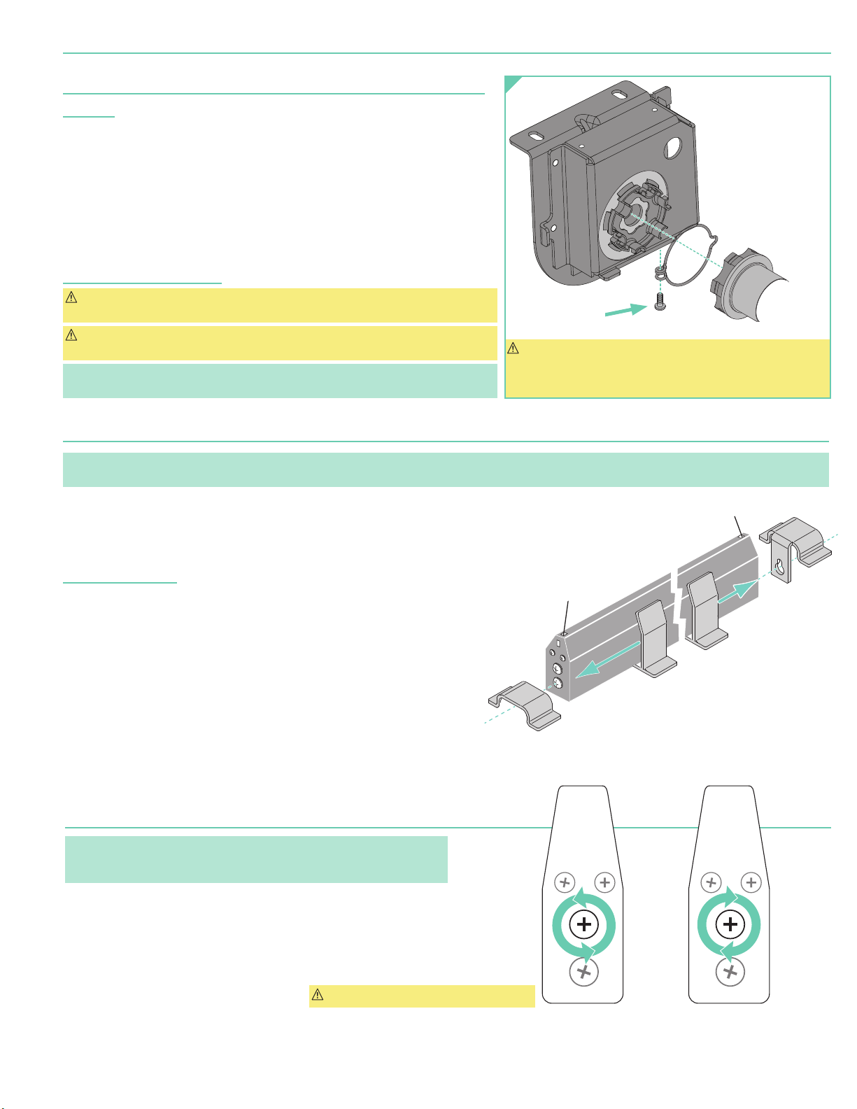
MOTOR RETAINING
Figure 2
SPRING AND
SCREW
Ceiling and Wall Installation:
CAUTION: Product is very heavy: Installer must provide adequate attachment hardware
and anchors as required. Installer must also ensure that structure is of adequate strength.
CAUTION: Case must be mounted low enough from ceiling to gain access to
bracket screws.
Please Note: Do not use a power screwdriver to tighten screw. Maximum torque for
tightening screw is 5 nm.
Motor Retaining
Screw
(included)
CAUTION: Do not remove the roller assembly from the case
unless necessary for repairs. If the roller assembly is removed,
be sure motor is fully re-seated in the bracket, and re-secure it
carefully with the motor retaining spring and screw.
Section 3 - Operation
Please Note: Before fully operating screen: For Targa, remove tape; on Premier, lower viewing surface enough to fully expose shipping brackets, then remove
shipping brackets by loosening screws, removing end shipping brackets, sliding center shipping brackets off dowel, and re-tightening screws
(Fig. 3)
.
220V Single Station Control — 3-position up-off-down switch permits operation to be stopped at any point. Factor y adjusted limit
switches automatically stop screen when fully down or fully up.
220V Multiple Station Control — Switches similar in appearance to 220V Single Station Control. Screen stops when switch is released
and may be restarted in either direction. Factory adjusted limit switches stop screen automatically when fully down or fully up.
For LVC-IV Controls:
24V Control — Three-button up-stop-down switch
sequence. Factory adjusted limit switches automatically stop screen when fully down or fully up.
1.
The key-operated power supply switch controls power to unit and switches. When it is “off”,
switches will not operate. Key may be removed from switch in either “on” or “off” position.
2.
A three-position key switch permits screen to be operated directly by key. In this case,
screen operator must always have a key.
RS232 / Ethernet — Serial communication and network communication available.
Plug & PlayTM — Supplied with a 9'8"
Screen is equipped with a handheld remote or 3-position operating switch.
Three positions
Factory adjusted limit switches automatically stop screen when fully down or fully up.
(up-off-down)
permit operation to be stopped at any point.
(2.9m)
Section 4 - Tab-Tension Adjustment Procedure
Please Note: The Draper Tab-Tensioning System is factory-set, and under
normal circumstances will not require field adjustment. If wrinkles are observed,
however, follow the adjustment procedure
(es)
stop at any point desired, operate in any
cable lead. No wiring is necessary.
(Fig. 4)
.
END OF
DOWEL
Figure 4
Figure 3
END OF
DOWEL
CAUTION: Do not touch or bend surface.
PUSH & TURN
COUNTER-CLOCKWISE
to RELEASE TENSION
PUSH & TURN
CLOCKWISE
to INCREASE TENSION
Page 4
ellow Socket—Down
Left hand motor:
White Socket—Up
Yellow Socket—Down
Right hand motor:
White Socket—Down
Yellow Socket—Up
Left hand motor:
Right hand motor:
W
aterfall RollStandar
Motor
End
Audience
Side
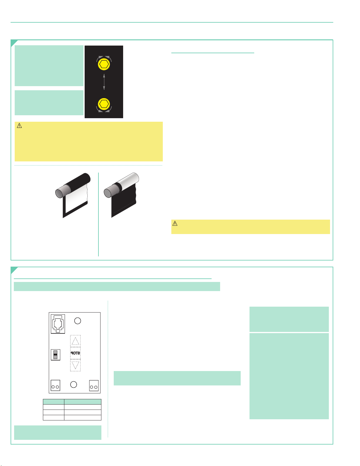
DOWN Limit (I)
Clockwise decreases
down travel.
UP Limit (II)
Counterclockwise
increases up travel.
Premier XL / Targa XL 220V
Section 5 - Limit Adjustments
page 4 of 8
Please Note: Screen limits
are factory set for optimum
performance of the screen. Any
adjustment of these limits could
void the warranty. Please check
with Draper prior to resetting
screen limits.
Please Note: If screen is “Right
Hand Motor,” the WHITE/DOWN
(I)
and YELLOW/UP
screws are reversed
CAUTION:
- Be sure all switches are in “off”
position before adjusting limit
switches.
- Be prepared to shut off manually
while testing.
(II)
limit
(Fig. 10)
.
Figure 10
Motor
End
Audience
Side
White Socket—Down
Yellow Socket—Up
White Socket—Up
Yellow Socket—Down
I
+
- Screen may be damaged by
- Motor must be installed so that
d Roll
+
I
lowering it too far and
exposing roller.
limit switches are pointed down.
Motor
End
Back
Side
Reverse Roll
Left hand motor:
White Socket—Down
Yellow Socket—Up
Right hand motor:
White Socket—Up
Y
Figure 9
DOWN Limit
Clockwise
decreases
down travel.
UP Limit
Counterclockwise
increases up travel.
(II)
(I)
:
:
Section 5.1 - Standard Motors
Section 5.1.1 - "Down" Limit Adjustment
To Reduce Screen Drop:
1.
Raise screen surface approximately 1'
and turn off.
2.
Turn DOWN
3.
Test by lowering screen. Repeat steps 1 & 2 until desired position is
reached.
To Increase Screen Drop:
1.
Lower screen to down limit.
2.
With down switch on, turn DOWN
(3 screw turns = ½ roller revolution)
3.
Test by raising screen approximately 1'
down limit.
4.
Repeat steps 2 and 3 until desired position reached.
(I)
limit screw clockwise
(Fig. 9)
(requires
5/32
(30 cm)
above desired setting
(3 screw turns = ½ roller revolution)
(I)
limit screw counterclockwise
to increase drop.
(30 cm)
then down to new
" (4 mm) hex key wrench)
Section 5.1.2 - "Up" Limit Adjustment
If Screen Raises Too High:
1.
Lower screen surface approx. 1'
2.
Turn UP
(II)
limit screw clockwise
3.
Test by advancing screen up.
4.
Repeat steps 1 through 3 until desired position is reached.
If Screen Needs to Raise Higher:
1.
Lower screen surface approx. 1'
2.
With UP switch on, turn UP
(3 screw turns = ½ roller revolution)
3.
Repeat steps 1 and 2 until desired position is reached.
CAUTION: DO NOT allow dowel to wrap over roller when operating screen!
This could damage screen.
(30 cm)
below desired setting and turn off.
(3 screw turns = ½ roller revolution).
(30 cm)
below desired setting and turn off.
(II)
limit screw counterclockwise
.
.
Section 5.2 - Limit Adjustments for Motors with Internal Low-Voltage Controllers
Please Note: Hold STOP button for 3-5 seconds while in programming mode to reverse motor direction.
Figure 11
BACK VIEW OF WALL SWITCH
To Motor
with
Built-In (ILT)
Low Voltage
Slide
Switch
C
o
m
+
m
5V
To Motor
Built-In (ILT)
Low Voltage
Please Note: 5V DC must be connected to
be able to set limits using the wall switch.
o
DC
n
with
POSITION FUNCTION
DOWN Set LOWER limit
UP Set UPPER limit
CENTER Normal Operation
D
o
U
w
p
n
1.
Connect internal low-voltage switch to motor via terminal
blocks, or via modular port using a four conductor modular
cable. When using modular cable, cable connectors MUST
NOT be crimped in reverse, as with standard telephone
cable.
(For Dry Contacts Wiring Diagram, see Section 8.)
2.
Set slide switch to lower position. Hold DOWN button
to move viewing surface to desired lower limit. If screen
moves in opposite direction, release DOWN button and hold
STOP button for 4 seconds. This reverses operation of UP
and DOWN switches.
3.
Move slide switch into center position. Wait several seconds.
Please Note: Do Not move slide switch from DOWN to UP
in one motion. This will set limits in same position.
4.
Set slide switch to higher position. Move viewing surface to
desired upper limit by holding UP button on wall switch.
5.
Return slide switch to center position to resume normal
operation.
6.
To set viewing surface to alternate format position, move
viewing surface to desired position and press STOP button.
Hold STOP button for at least 3 seconds to record position.
(F i g . 11)
Please Note: Press and release UP
button on switch to move screen to
upper limit. Press and release DOWN
button to move screen to lower limit.
• While motor is in motion, press
STOP button for less than 2
seconds to stop viewing sur face at
present position.
• Once motor is stopped, press
STOP button to move viewing
surface to alternate format position.
• Hold STOP button, when motor is
at rest or in motion, for 3-5
seconds to record new alternate
format position.
• Hold STOP button for 3-5 seconds
while in programming mode to
reverse motor direction.
Page 5
Premier XL / Targa XL 220V
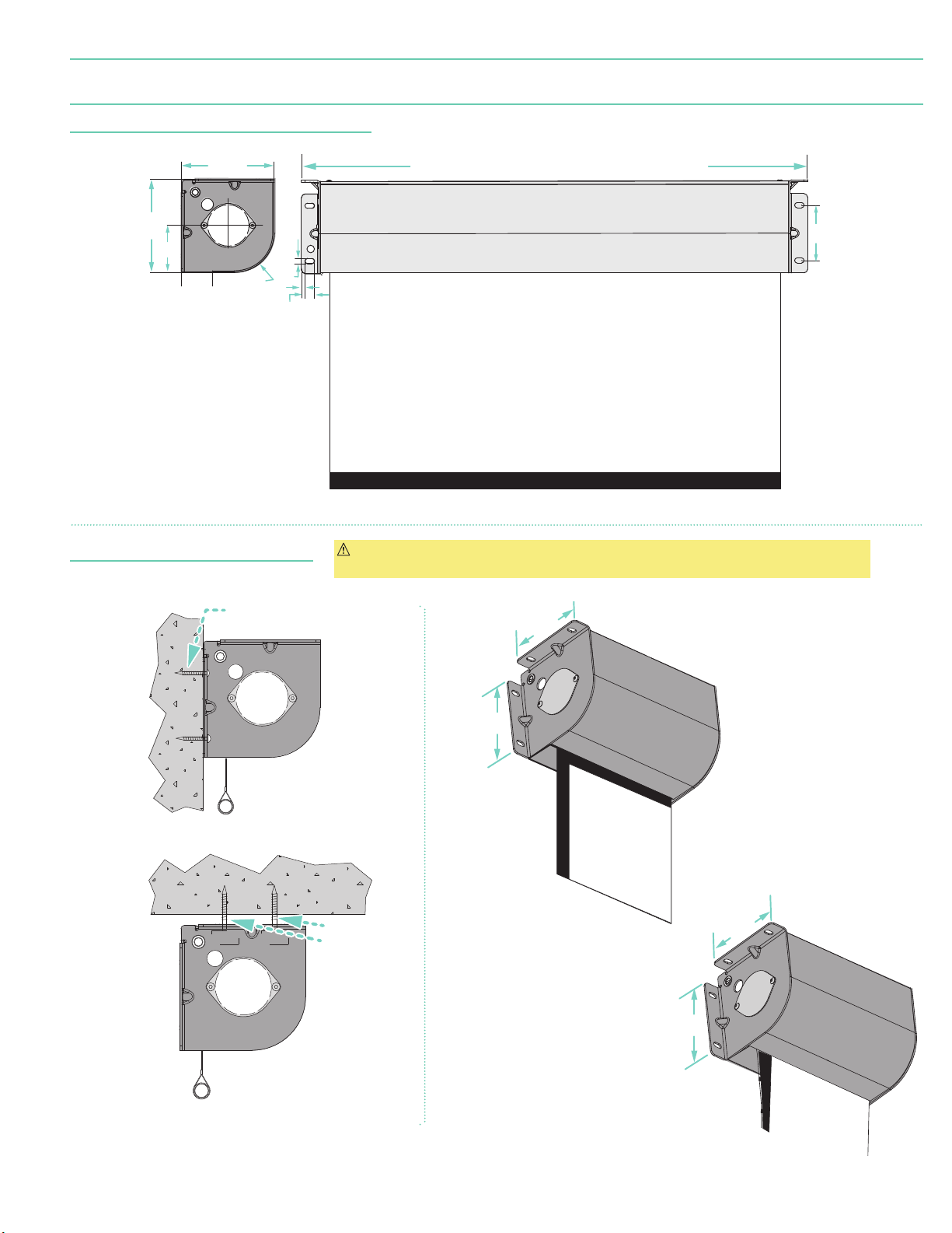
Section 6 - Dimensions and Methods of Installation
page 5 of 8
Case Dimensions*
(Premier Tab-Tensioned Surface Shown)
6 "
(171 m m)
3
"
(86 mm)
1
(40 mm)
Methods of Installation
6 "
(171 m m)
(10 mm)
R2
(73 mm)
"
(6 mm)
"
(Targa Dowel Shown)
"
"
(17 mm)
Case Length ≤ 191
Case Length > 191
"
(4.87m)
Case Width B
= Surface Width + 8
"
(4.87m)
= Surface Width + 8 "
(Varies)
"
(22.5cm)
(21.6cm)
4"
(102 m m)
"
CAUTION: Product is very heavy: Installer must provide adequate attachment hardware and
anchors as required. Installer must also ensure that wall or ceiling structure is of adequate strength.
Wall
Mounted
Ceiling
Mounted
Appropriate hardware
provided by installer.
Appropriate
hardware
provided
by installer.
Targa
6 "
(171 m m)
6 "
(171 m m)
Premier
6 "
(171 m m)
6 "
(171 m m)
Page 6
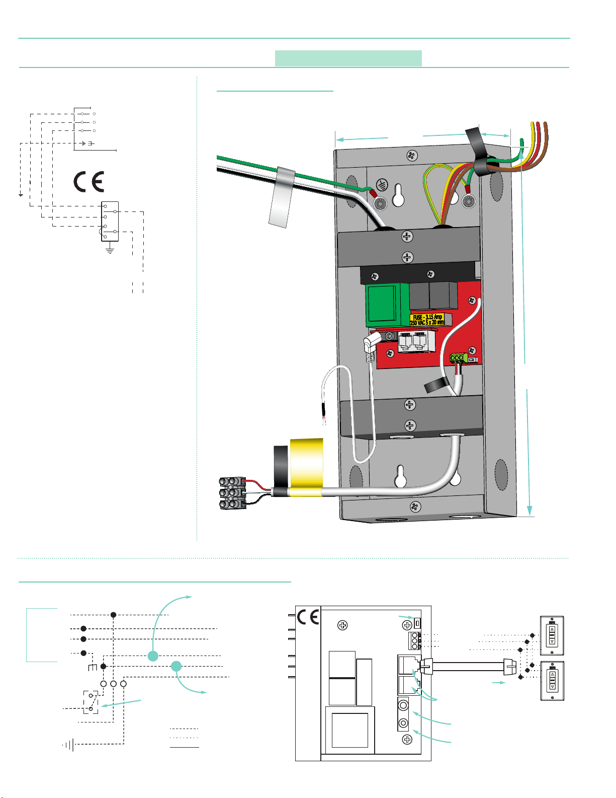
LVC-IV motor lead bundle
Wall Switch
External LVC-IV - Single or Multiple Projection Screen Wiring Diagram - 220V
INTERNAL SCREEN WIRING
TO: MOTOR LEADS
50 Hz.
)
Single Station Control
Premier XL / Targa XL 220V
page 6 of 8
Section 7 - Wiring Diagrams: Standard Motor
CE Approved
Internal Screen Wiring
Blue-220V (Common)
Brown-220V (Down)
Black-220V (Up)
Green/ Yellow (Motor Ground
Control
switch
Dashed wiring
by installer.
Neutral
220V,
L1
External LVC-IV Junction Box
Please Note: Do not wire motors in parallel.
4.5"
(114 mm)
AC POWER INPUT
MOTOR LEADS
2.214"
(56mm)
External LVC-IV - Single or Multiple Projection Screen Wiring Diagram
Blue
(Comm on)
Black
(Up)
Brown
(Down)
Green/Yellow
(Motor Ground)
To
230 VAC
L1
Line
N
GND
White - Common to screen & 230V AC Neutral
Location of key
operated on-off
switch if furnished.
Red - to screen
Brown - to screen
LVC-IV AC power in put bundle
Dashed wiring by electrician
Low-voltage wiring by others
Factory wiring
Yellow - to 230V AC-Hot
Black - to 230V AC-Hot
Green/Yellow
(direct ional)
(directional)
(Groun d)
10.39"
RF Antenna
Wire
DRY CONTACT
CONTROLLER.
CLOSURE ONLY.
APPLYING VOLTAGE
HERE WILL DAMAGE
WARNING
WALL SWITCH
Receiver
Button
3 Button Wall Switch
DOWN - Black
COM - White
(264mm)
UP - Red
Electr ically S traigh t
Data C able to mo re
FUS E - 3.15 AMP
25 0 VAC 5x 20 mm
LVC-IV mod ules.*
RS232/485
Inputs/Outputs
IR Eye Input
Low-Voltage
Trigger
4-28 VDC
*A maximum of six (6)
LVC-IV module s can
be linked together.
Page 7
all Switch
INTERNAL SCREEN WIRING
GND
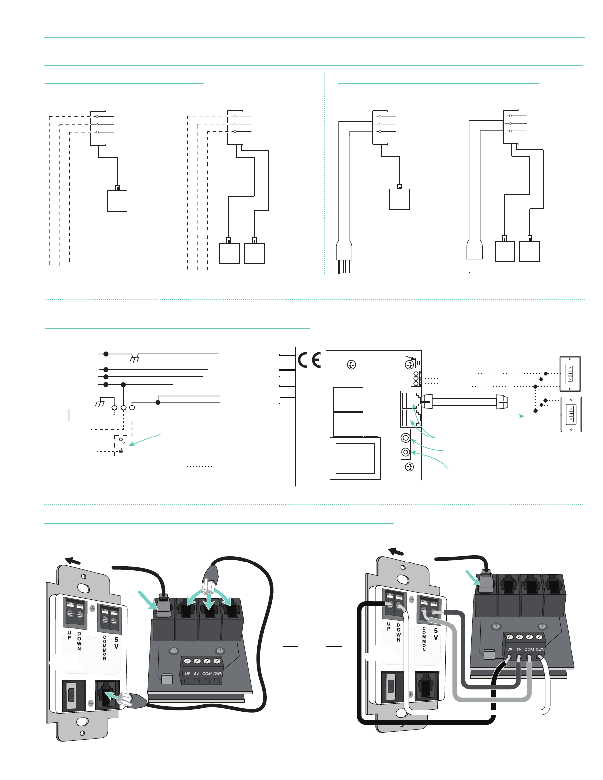
Internal LVC-IV - Single or Multiple Projection Screen Wiring Diagram
Single Low-Voltage Control
Multiple Low-Voltage Controls
Single Low-Voltage Control
Multiple Low-Voltage Controls
ILT Data Cable Connection
Dry Contacts
Premier XL / Targa XL 220V
Section 8 - Wiring Diagrams: Motors with internal low-voltage controller
page 7 of 8
220V Motor
(with Internal Low Voltage Controller)
Internal Screen Wiring
Blue (Neutral)
Brown
Green (Ground)
Dashed wiring
by electrician
Data Cable
Dashed wiring
by electrician
Internal Screen Wiring
Blue (Neutral)
Brown
Green (Ground)
Data
Cables
Wall Switch,
RF or IR
To 220V Line
Receiver,
or integrated
control system
To 220V Line
Wall Switches,
RF or IR
Receivers,
or integrated
control systems
Internal LVC-IV - Single or Multiple Projection Screen Wiring Diagram
Green/Yellow
(Motor Ground)
Black (Up)
Brown (Down)
Blue (Common)
N
To
230 VAC
L1
Line
White -Common to screen & 230V AC Neutral
Location of key
operated on-off
switch if furnished.
Green/Yellow (Ground)
Red-to screen (directional)
Brown-to screen (directional)
Yellow-to 230V AC-Hot
Black-to 230V AC-Hot
Dashed wiring by electrician
Low-voltage wiring by others
Factory wiring
Plug & Play 220V Motor
Internal Screen Wiring
Blue (Neutral)
Brown
Green (Ground)
Data Cable
Wall Switch,
RF or IR
Receiver,
or integrated
control
system.
220V
Receiver
Button
FUSE - 3.15 AMP
250 VAC 5x20mm
(with Internal Low Voltage Controller)
220V
3 Button Wall Switch
DOWN - Black
COM - White
UP - Red
Electrically Straight
Data Cable to more
LVC-IV modules.*
RS232/485
Inputs/Outputs
IR Eye Input
*A maximum of six (6)
Low-Voltage
Trigger
4-28 VDC
LVC-IV modules can be
linked together.
Internal Screen Wiring
Blue(Neutral)
Brown
Green (Ground)
Data
Cables
Wall Switch,
RF or IR
Receiver,
or integrated
control
system.
W
Motor with Internal Low-Voltage Controller: Switch-to-Motor
T
O
M
O
T
O
R
MOTOR
DATA CABLE
Data Cables to
switches or
additional motors
(Dry Contacts or Data Cable connection)
OR
Back of
Back of
Wall Switch
Wall Switch
Please Note: This Splitter/Jack is located
inside the junction box of your screen.
Back of
Back of
Wall Switch
Wall Switch
T
O
M
O
T
O
R
MOTOR
DATA CABLE
Please Note: 5V DC must
be connected to set limits
using the wall switch.
Page 8
Premier XL / Targa XL 220V
page 8 of 8
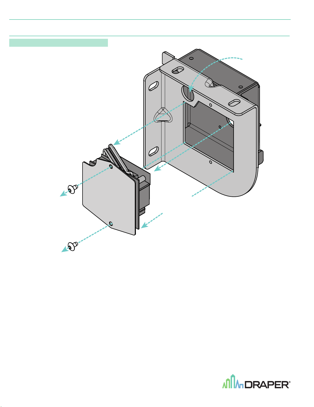
Section 9 - Accessing Internal Low-Voltage Control Unit
PLEASE NOTE: Applies ONLY if Unit is built into case.
1..
Locate LVC-IV Unit.
2.
Remove the two
end of the screen housing.
3.
Remove the access panel with the LVC-IV from the
screen housing.
(2)
star head screws from the motor
(LVC-IV)
Electrical
Connection
Hole*
Remove two (2)
Hex head screws
from endcap.
Remove
access panel
with LVC-IV.
*A second electrical connection hole
is included in the screen housing
in order to separate Low-Voltage
and High-Voltage Wiring.
 Loading...