

Page 1
SCREWDRIVER
PENCIL
StyleLine
Fixed screen with bezel trim or borderless option
Overview - Packing & Unboxing
STYLELINE
INSTRUCTIONS
INSTA LL ATION & OPERATION
1
5 5
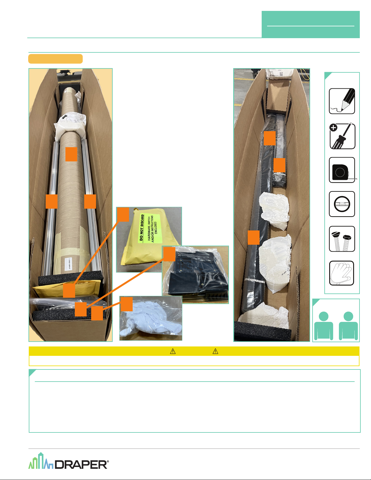
1. Screen Surface
(packed in cardboard tube)
2. Hardware & Instructions
3. Corner Brackets
4. Gloves
(for handling screen surface)
5. Screen Subframe Pieces
6. Bezel Trim Pieces
2
TOOLS
REQUIRED
6
6
TAPE MEASURE
LEVEL
6
3
2
4
3
4
CAUTION
Read and understand all warnings
Contents
Overview - Packing & Unboxing ..........................................................................1
PLEASE READ - Safety & Installation Information ...........................................2
Overview - Components .......................................................................................3
Section 1 - Assembling Screen Subframe ........................................................4
Section 2 - Hanging Brackets and Testing Screen Placement ......................5
Section 3 - Preparing for Screen Surface Attachment, Optional Lighting ..6
HARDWARE
WHITE GLOVES
RECOMMENDED
PERSONNEL
(P. 2)
before beginning installation.
Section 4 - Attaching Screen Surface to Screen Subframe...........................7
Section 5 - Adjusting Screen Surface ................................................................8
Section 6 - Applying Adhesive Tabs ...................................................................8
Section 7 - Attaching Bezel Trim to Screen Subframe....................................9
Section 8 - Dimensions ................................................................................ 10 -12
Section 9 - Mounting Bracket Dimensions .....................................................12
If you have any difficulties installing or servicing your
StyleLine screen, call your dealer or Draper, Inc.
(by others)
21
Draper, Inc. | 411 S. Pearl St. Spiceland, IN 47385
draperinc.com | 765.987.7999 | 800.238.7999
© 2024 All Rights Reserved | FORM: StyleLine_Inst24
Page 2
StyleLine
page 2 of 12
PLEASE READ - Installation Information
CAUTION: Installer must provide adequate attachment hardware and anchors as required. Installer must also ensure that
structure is of adequate strength.
1.
Read instructions through completely before
proceeding.
2.
Follow instructions carefully. Installation contrary to
instructions invalidates warranty.
3.
Screen should be accessible for complete removal
should surface become damaged or should other
service be required.
4.
Screen should be installed level
level)
.
5.
Nothing should be fastened to screen frame
or viewing surface.
6.
Ensure all parts are present.
Please Note: Installer may need to modify subframe to accommodate lighting features. Ensure that such modifications do not compromise structural
integrity of the subframe or screen assembly.
Please Note: Custom products/installations may not be reflected by this document. Call Draper, Inc. with any questions about product installation.
(using a carpenter’s
7.
Regardless of mounting method, screen should be positively
and securely supported so that vibration or even abusive pulling
on viewing surface will not cause case to loosen or fall. Installer
must ensure that fasteners used are of adequate strength and
suitable for mounting surface chosen.
8.
Draper recommends using two people for assembly and installation. When lifting
assembled screen, do not lift at only one corner; lift at both corners. Lifting by one corner
could result in damage to the screen frame, especially on large screens.
9.
The ideal temperature range for assembling permanently tensioned screens to prevent
damaging the surface is 68°- 78° F
temperatures may damage surface and void warranty.
10.
Use extreme care when handling TecVision surfaces. To prevent damaging the TecVision
viewing surface, Draper strongly reccommends using white gloves.
(20°- 26° C)
. Assembling below recommended
RECOMMENDED
PERSONNEL
21
PLEASE READ - Safety Information
Important Safety Information Important Safety Information
Improper installation and use of the StyleLine Projection Screen can result in serious injury or death. Primarily, injuries can occur if the unit falls due to
imprecise installation, mishandling of the screen during installation or installation on an insufficient wall or ceiling structure. Please use extreme care.
1.
Please read the following installation guidelines thoroughly and follow them
carefully. Failure to do so may cause product to fall or otherwise fail, and
could result in serious injury.
2.
Installation and calibration of the unit should only be performed by an
authorized, qualified, and experienced professional.
3.
Do not affix the unit to wall or ceilings that have inadequate strength to
permanently hold the unit during use. It is the owner’s and installer’s
responsibility to confirm the wall or ceiling to which the unit attaches is
sufficient to permanently hold the weight and stress loads of the unit at all
times. Draper, Inc., is not responsible for improper installation, application,
testing or workmanship related to the product at place of installation.
4.
It is the installer’s responsibility to make sure appropriate fasteners are used
for mounting.
1.
Look for any job site conditions that could interfere with installation or
operation of the system.
2.
Read carefully and be sure to understand all installation instructions and
all related operations manuals. These instructions are intended to serve
as a guide for the installer and owner. They should be followed closely and
combined with the expertise of experienced qualified installers. Draper,
Inc., is not responsible for improper installation, application, testing, or
workmanship related to the product at place of installation. Please retain all
instructions for future use.
WARNING
5.
All brackets and other hardware must be installed level. Unit must be level
and square.
6.
Never leave the area during installation or maintenance, unless it is secure
and safe.
7.
Screen may need to comply with local, state, or district rules and regulations,
in particular when installed in schools. All applicable rules and regulations
should be reviewed before installation and use.
8.
Failure to precisely follow installation guidelines invalidates all warranties.
9.
Custom products/installations may not be reflected in this manual. Call
Draper, Inc., if you have questions regarding your installation.
Before Beginning Installation
3.
Open cartons lengthwise.
4.
Locate and lay out all pieces.
5.
Inspect all boxes to make sure you have received the proper parts.
6.
If you have any difficulties with installing, servicing, or operating your
system, call your dealer or Draper, Inc., 765 -987-7999.
Page 3
StyleLine
Overview - Components
Please Note: Installer may need to modify subframe to accommodate lighting features. Ensure that such modifications do
not compromise structural integrity of the subframe or screen assembly.
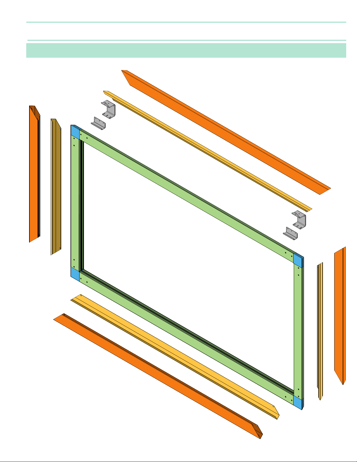
FLY BRACKET
MOUNTING BRACKET
(for flown screens)
3" HORIZONTAL BEZEL TRIM PIECE
page 3 of 12
3"
VERTICAL BEZEL TRIM PIECE
" HORIZONTAL BEZEL TRIM PIECE
" VERTICAL BEZEL TRIM PIECE
" HORIZONTAL BEZEL TRIM PIECE
3" HORIZONTAL BEZEL TRIM PIECE
VERTICAL BEZEL TRIM PIECE
3"
" VERTICAL BEZEL TRIM PIECE
Page 4
BLANKET
OR
DROP CLOTH
StyleLine
page 4 of 12
Section 1 - Assembling Screen Subframe
Please Note: Installer must provide adequate attachment hardware and anchors as required. Installer
must also ensure that structure is of adequate strength.
Please Note: Installer may need to modify subframe to accommodate lighting features. Ensure that
such modifications do not compromise structural integrity of the subframe or screen assembly.
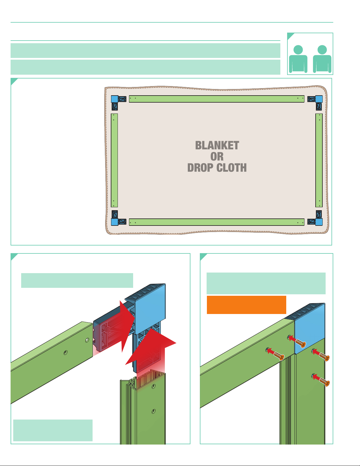
Create a staging area
1.
for assembling screen:
A. Place the carboard roller
containing Screen Surface
and the wrapped Bezel Trim
Pieces
B. Spread blanket, drop cloth,
or other soft protective
surface over a large table
or floor space.
C. Unwrap and lay out in the
general order of assembly:
• Subframe sections
• Corner Brackets & Screws
• Mounting Brackets
• Mounting Screws
(if applicable)
aside.
(Subframe placed face UP,
hook & loop side DOWN)
RECOMMENDED
PERSONNEL
21
Insert the Subframe sections
2.
onto the Frame Corner Brackets. 3.
Please Note: Attach long sides to corner
brackets first, then attach short sides.
Please Note: If necessary,
screen can be assembled
while in an upright position.
Secure Frame Corner Brackets
with provided screws.
Please Note: Screws are countersunk and
must be flat & flush with subframe surface
in order for screen surface to lay smoothly.
DO NOT attach screen
surface or bezel trim yet.
Page 5
StyleLine
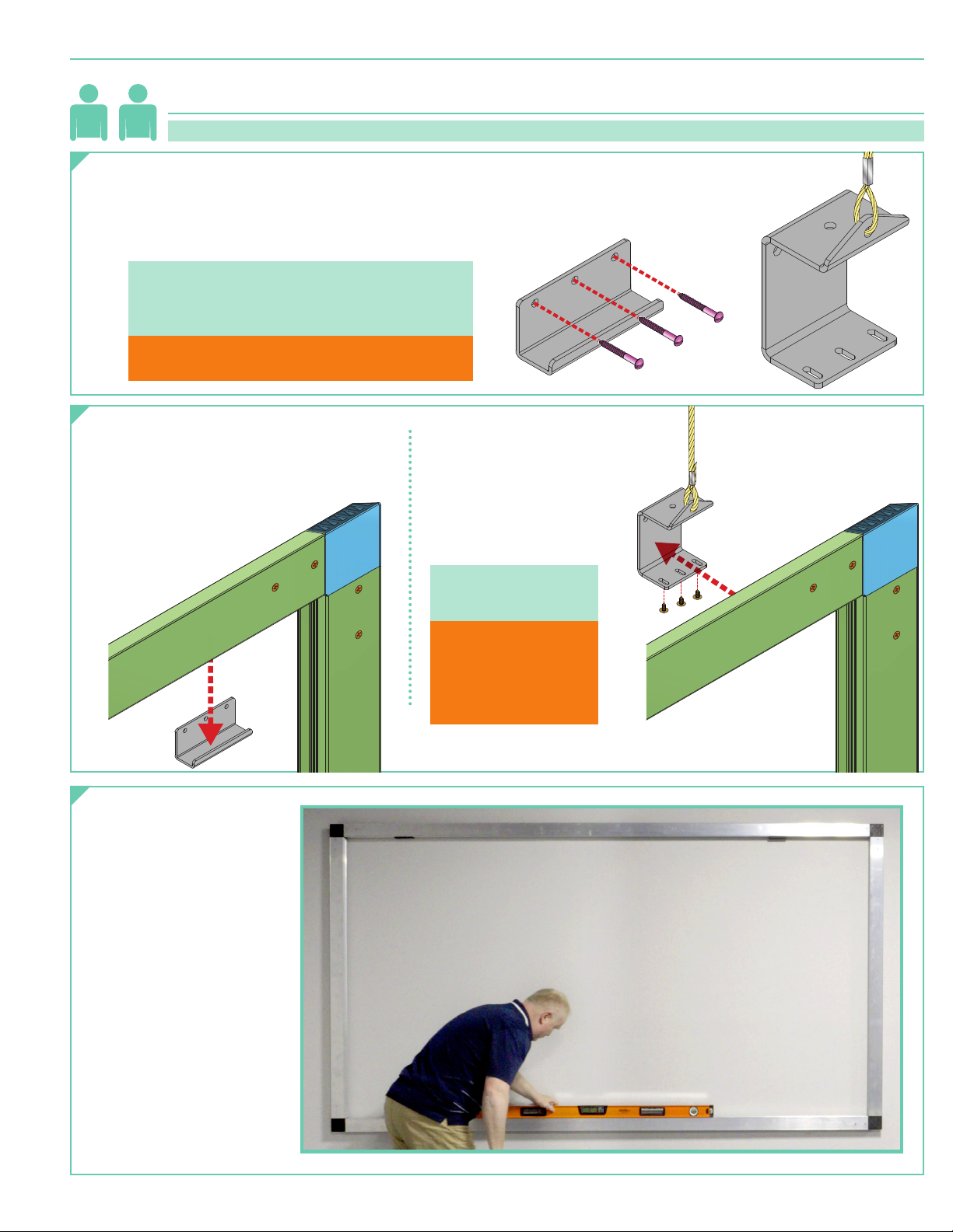
Section 2 - Hanging Brackets and Testing Screen Placement
21
Please Note: This process is best accomplished with at least 2
(two)
installers.
page 5 of 12
Test Screen Subframe placement before attaching
1.
screen surface to frame. Install Mounting Brackets to
mounting surface or fly cables, approximately 16"-24"
in from edge. Larger screens will require additional
bracket installed at center mounting point.
Please Note: Installer must provide adequate
attachment hardware and anchors as required.
Installer must also ensure that mounting
structure is of adequate strength.
Caution: DO NOT use the fly bracket set
screws as mounting hardware!
Hang subframe on the wall
2.
or from fly cables.
For Wall Mounted Screens:
Lift the assembled subframe up and over
the Wall Mounting Brackets.
Carefully settle subframe on the
Wall Mounting Brackets.
Wall
Bracket
For Flown Screens:
Insert the assembled subframe
into the Fly Mounting Brackets
and tighten set screws.
Please Note: Adjust
set screws to level
subframe.
Caution: DO NOT
use the fly bracket
set screws
as mounting
hardware!
Fly
Bracket
Ensure subframe is
3.
level and lays flat
when installed on
mounting brackets.
Page 6
FRONT OF
SCREEN SURFACE
BLANKET
OR
DROP CLOTH
StyleLine
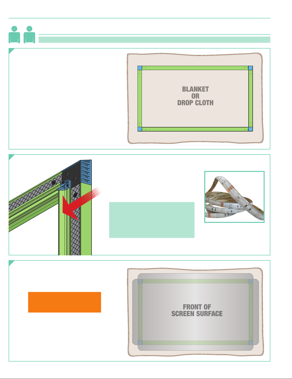
Section 3 - Preparing for Screen Surface Attachment, Optional Lighting
page 6 of 12
21
Remove subframe from mounting brackets
1.
and lay it on top of blanket, drop cloth, or
other soft protective surface in staging
area, front side facing up, hook & loop
side facing down.
Please Note: This process is best accomplished with at least 2
Optional LED backlighting
2.
be installed into the ½"
on the back of the frame. If lighting
strips are being installed, apply them to
back of screen subframe now.
(13mm)
(two)
installers.
(Subframe placed face UP,
hook & loop side DOWN)
(by others)
can
channel
Remove Screen Surface Fabric from
3.
cardboard tube and carefully slide end
from inner cardboard tube. Set aside
foam padding sheets for later use.
Please Note: Use included soft
gloves whenever handling
screen surface.
Spread on top of subframe. Align each
4.
corner of subframe with the cut
corners of the screen surface.
Please Note: Installer may need to
modify subframe to accommodate
lighting features. Ensure that such
modifications do not compromise
structural integrity of the subframe
or screen assembly.
LED light by others.
Page 7
BACK OF
SCREEN
SURFACE
1
2 4
3
FRONT OF
SCREEN SURFACE
B
C
StyleLine
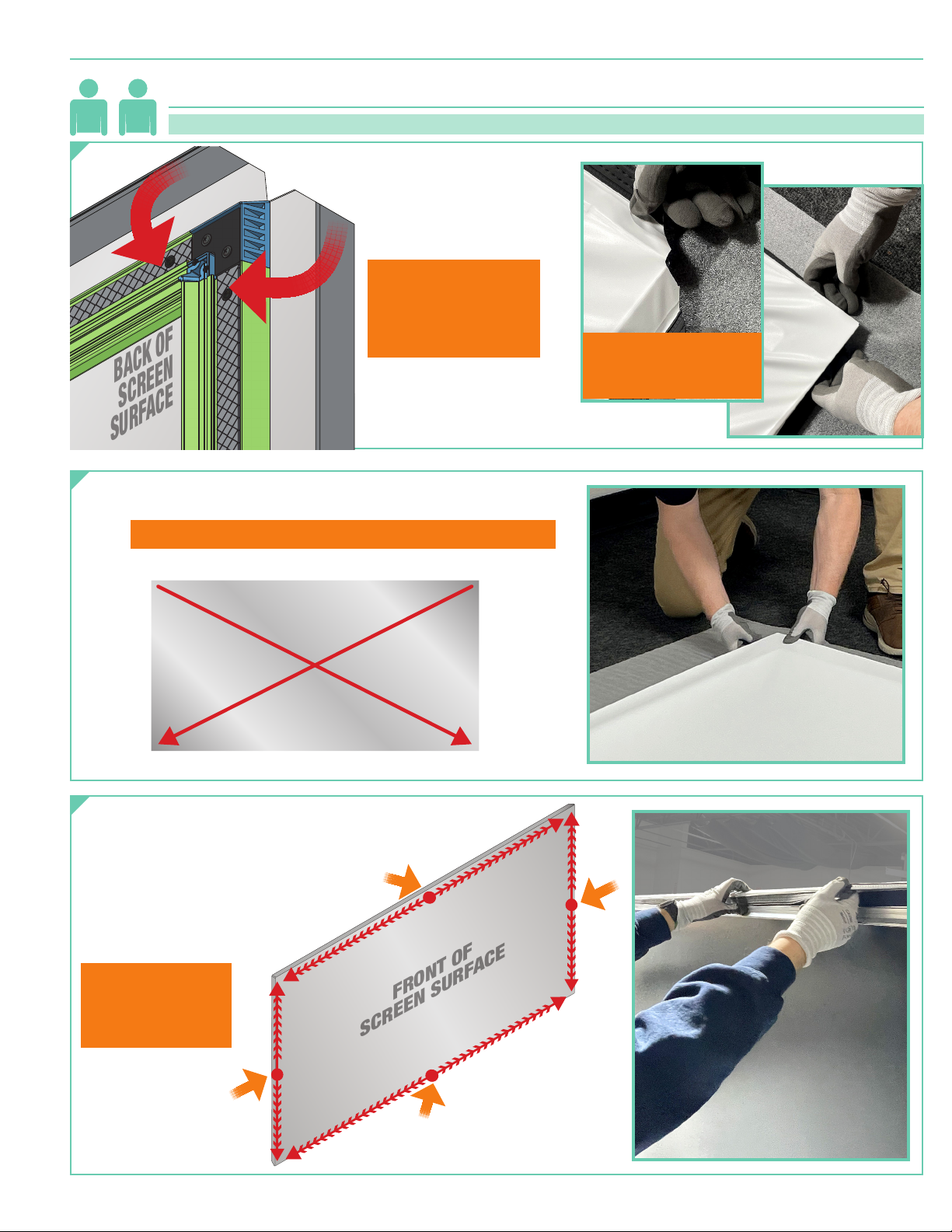
Section 4 - Attaching Screen Surface to Screen Subframe
page 7 of 12
21
Attach the screen surface to the opposite diagonal corner of the
2.
subframe, and repeat on the other corners, as shown below.
Please Note: This process is best accomplished with at least 2
At first corner, pull the edge
1.
of the screen surface fabric
and wrap it snugly around
the subframe, joining the
hook and loop strips.
Please Note: Use
soft white gloves
whenever handling
front of screen
surface.
Caution: Take care not to deform or tear screen surface.
(two)
installers.
Align inset corner of
screen surface with
corner of bracket.
Tilt/stand screen upright, and continue by attaching
3.
screen surface to center points between the corners,
and work from there to attach screen along
the frame, joining the hook
and loop strips. Gently pull
and smooth screen surface
while attaching it
to the frame.
Caution:
Take care not to
deform or tear
screen surface.
A
D
Page 8
StyleLine
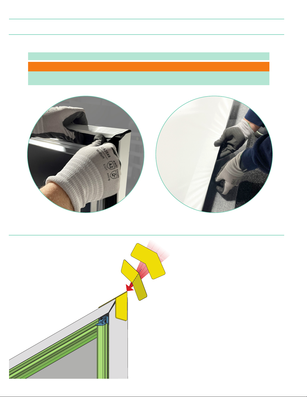
Section 5 - Adjusting Screen Surface
Review screen surface for ripples and flatness of screen surface. GENTLY undo each hook and loop strip and
CAREFULLY pull screen surface as necessary to make small adjustments. Repeat as necessary.
page 8 of 12
PLEASE NOTE: Adjust horizontal
Caution: Take care not to deform or tear screen surface.j
Please Note: Some wrinkles will resolve when screen is vertical for a few minutes as fabric settles,
acclimates, and relaxes.
(long)
sides FIRST, then adjust vertical
(short)
sides. Repeat as necessary.
Section 6 - Applying Adhesive Tabs
Fold and adhere
2.
protective tabs
to screen corners.
(for Borderless screen option ONLY)
If no Bezel pieces were
3.
ordered, screen is now
ready to hang. Stand
screen upright, review
for fit and finish, and
hang screen as outlined
in Section 2 on Page 4.
Page 9
BACK OF
SCREEN
BACK OF
SCREEN SURFACE
StyleLine
page 9 of 12
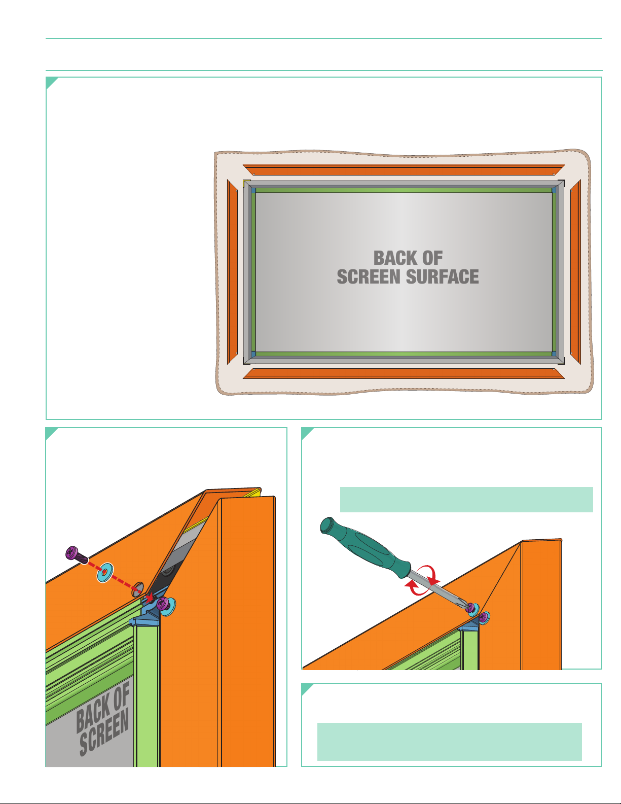
Section 7 - Attaching Bezel Trim to Screen Subframe
Spread out the foam padding sheets from the screen
1.
surface tube and lay subframe and screen on top, with
surface facing DOWN. Arrange top and side Bezel pieces
in general order of assembly.
Slide Bezel Trim pieces
2.
onto subframe, aligning
holes with holes in the
corner brackets, in the
following order:
A. Bottom piece FIRST.
B. Side piece SECOND.
C. Side piece THIRD.
D. Top Piece LAST.
(Optional) (3
3/16
" version shown)
Align bezel trim piece holes with holes in
3.
subframe corner brackets and loosely
attach bezel trim pieces with provided
screws and washers.
Once all bezel trim pieces are aligned and loosely
4.
attached, tighten the screws and washers as necessary
to fasten bezel trim pieces to the screen and draw the
mitered corners snugly together.
Please Note: Press mitered corners together while
tightening for best results.
Stand screen upright, review for fit and finish, and
5.
hang screen as outlined in Section 2 on Page 4.
Please Note:
Some wrinkles will resolve when screen is vertical for a
few minutes as fabric settles, acclimates, and relaxes.
Page 10
StyleLine
Viewing Surface Height + 1
BEZEL STYLELINE
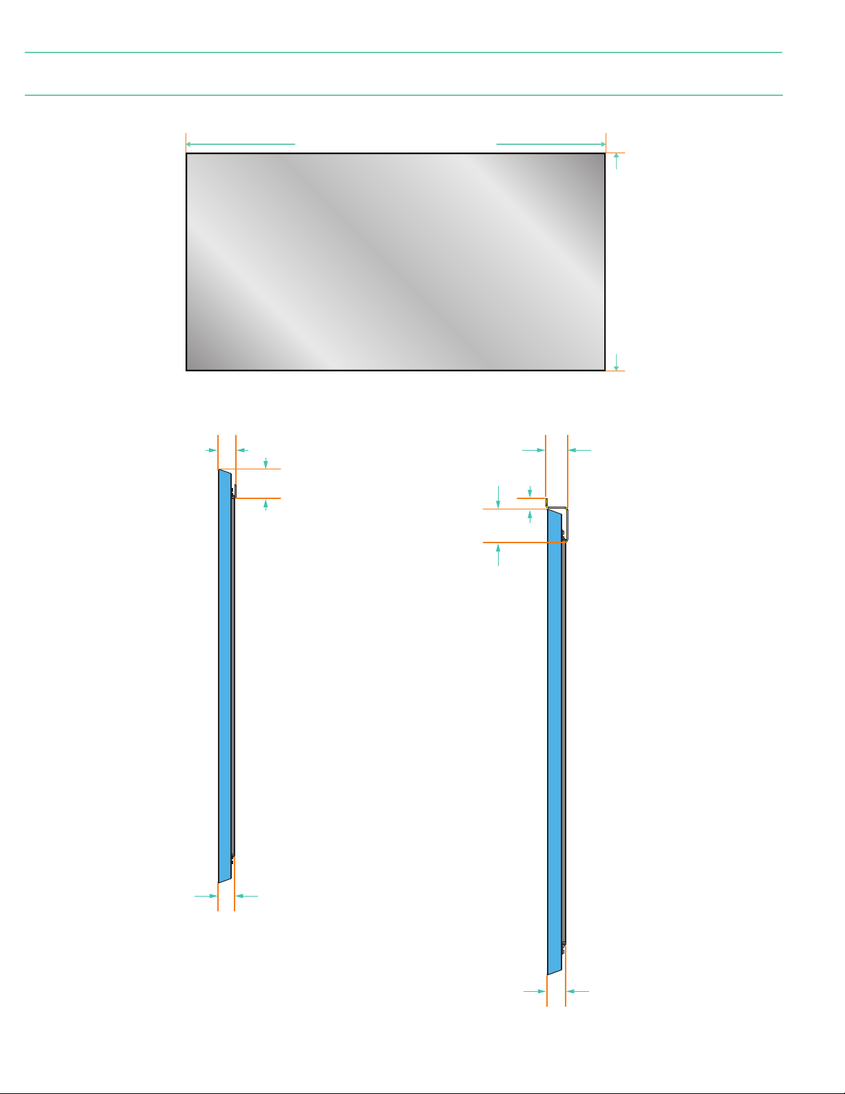
Section 8 - Dimensions
TRIM FRAME
BEZEL WALL MOUNT
(16mm)
Viewing Surface Width + 1
Viewing Surface
(32mm)
BEZEL FLOWN
page 10 of 12
(32mm)
1
(48mm)
3
(79mm)
3
(79mm)
1
(26mm)
2
(52mm)
1
(44mm)
1
(44mm)
Page 11
StyleLine
Viewing Surface Height + 6
3
BEZEL STYLELINE
page 11 of 12
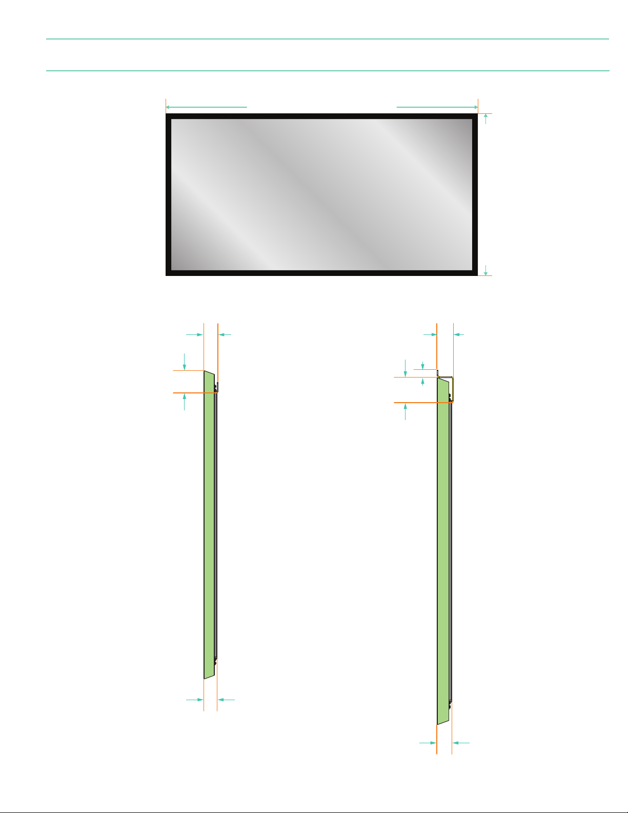
Section 8 - Dimensions
TRIM FRAME
3
BEZEL WALL MOUNT
(continued)
2
(51mm)
(81mm)
Viewing Surface Width + 6
Viewing Surface
(162mm)
3
(24mm)
(162mm)
BEZEL FLOWN
2
(52mm)
3
(79mm)
3
(81mm)
1
(48mm)
1
(48mm)
Page 12
StyleLine
(13m m)
(38m m)
3
(10m m)
(70mm)
(38m m)
2
1
1
(38m m)
Viewing Surface Height + Ø
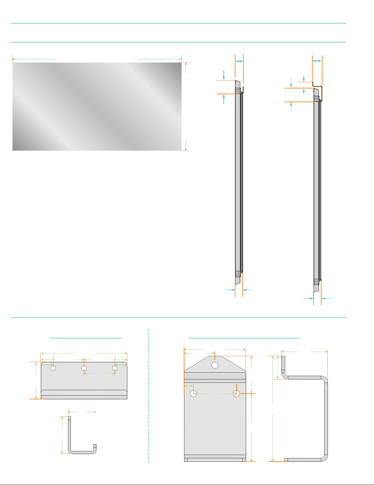
BORDERLESS STYLELINE
page 12 of 12
Section 8 - Dimensions
Viewing Surface Width + Ø
Viewing Surface
(continued)
BORDERLESS WALL MOUNT
1
(43mm)
2
(71mm)
BORDERLESS FLOWN
2
(52mm)
(32mm)
2
(73mm)
1
Section 9 - Mounting Bracket Dimensions
(29m m)
(89mm)
1
1
(32mm)
(44mm)
1
(44mm)
(13m m)
1
1
1
(40mm)
1
(40mm)
Mounting Bracket for flown screensWall Mounting Bracket
(64mm)
1
(32mm)
(24mm)
1
1
(44mm)
4
2
(108 mm)
(48m m)
 Loading...