

Page 1
Salara
Specifi cations—Salara
mounting. Elliptical case of extruded alu mi num, with painted white fi nish. Injection
molded plastic endcaps with domed contour shape, fi nished to match case. Case
shall accept adjustable mounting brackets that snap easily into place and slide
anywhere along length of case.
Electrically operated 110-120V AC, 60 hz. 3-wire mo tor mounted inside
3
1
/4" (4.4 cm) diameter roller, in stant ly re vers ible, lifetime lu bri cat ed, with thermal
over load pro tec tor and elec tric brake. Preset, ac ces si ble limit switches. Draws 1.1
amp.
Viewing surface of (matt white/optional glass beaded/optional High Contrast Grey/
optional AT1200/optional AT Grey), fl ame and mildew resistant. Fabric attached to
one-piece rigid steel roller. Bottom of viewing surface attached to
Please Check All Appropriate Selections
Select Viewing Surface:
Matt White
Optional Glass Beaded
Optional High Contrast Grey
Optional AT1200*
Optional AT Grey*
*Not recommended for screens smaller than 80" wide when used with LCD or DLP
projectors.
Select Wiring/Control Options:
Salara/Plug & PlayTM IR—10' (3 m) cord, built-in IR receiver, handheld IR
remote
Salara/Hardwire with Built-in IR—with hand-held infrared remote transmitter
Salara/Series M pull-down screen
Salara/Hardwire—This version of the Salara comes with one 110V-120V AC
3-position wall switch (silver wall plate with black rocker)
Total number of 110-120V AC switches ( switches operate independently)
Substitute white switch(es) for silver wall plate with black rocker
Serial or Network Communication (Please see and complete a Serial and
Network Screen and Lift Control Planning Sheet).
Optional Low Voltage Control Module (LVC-III)
24 Volt 3-Button Switch Number of 24V switches:
Radio Frequency Remote Control (only with 24v)
Infrared Remote Control (only with 24v)
Optional Key Operated Switch
Power Supply Key Switch (On-off)
3-Position Key Control
3-Position Switch with Hinged Key-Locking Coverplate
Optional Video Interface Control
VIC-115 (not compatible with LVC-III) Override Switch
VIC-12 (not compatible with LVC-III) Override Switch
VIC-6 (not compatible with LVC-III) Override Switch
Select Border/Drop Options:
Black Masking Borders (Standard on NTSC, HDTV & WideScreen sizes)
Extra Screen Drop (Total screen height cannot exceed 12' [366 cm])
Same color as viewing surface (standard on AV format screens)
Black (standard on all other formats)
Length of extra screen drop required
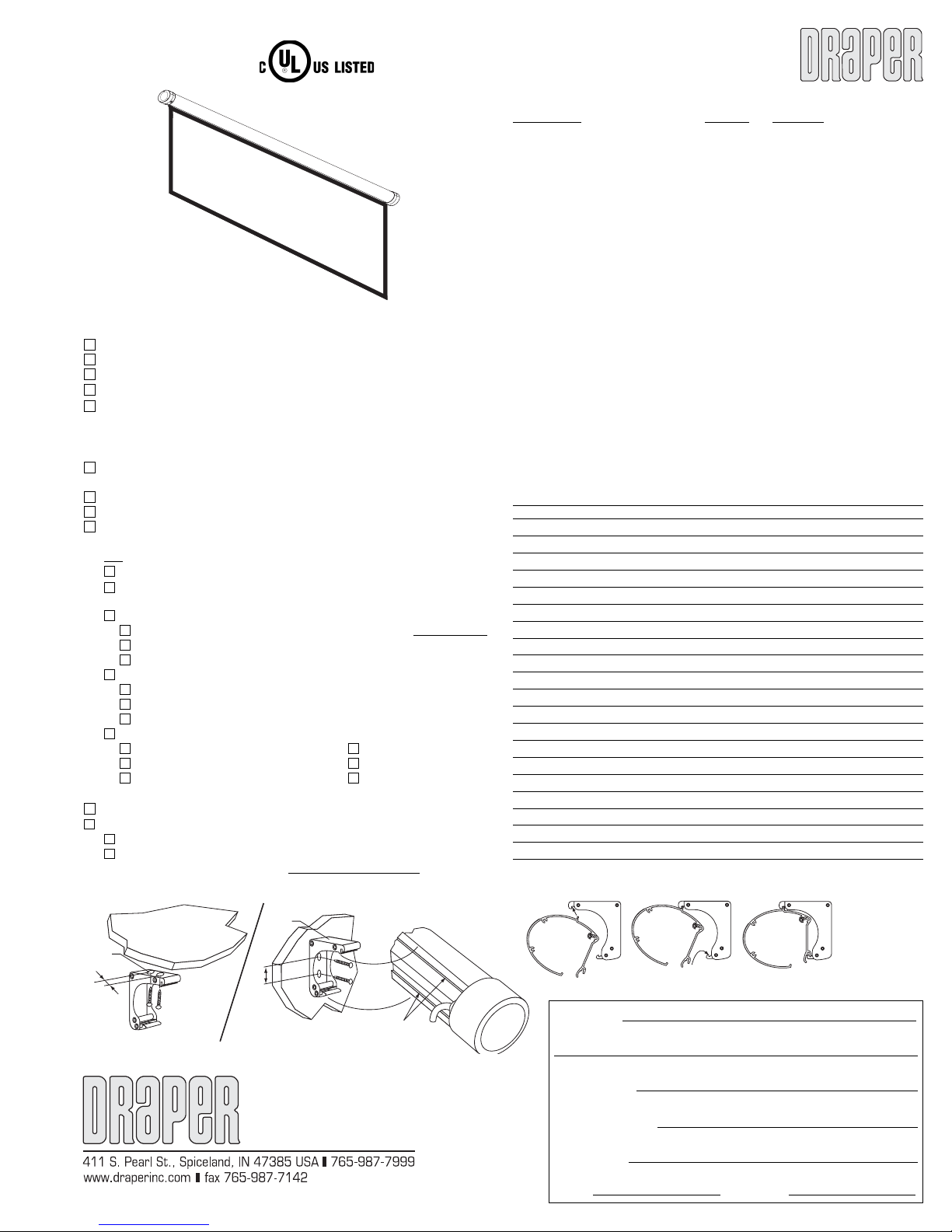
Salara—Method of Installation
Mounting
Bracket
Wall
1
/2"
1
Extrusions along
back of case
Mounting
Bracket
1
1
/2"
Ceiling
ameter roll formed steel dowel, fi nished white. Note: Matt white and glass beaded
surfaces up to 10' (3 m) high will be seamless. Entire unit certifi ed by Underwriters’
Laboratories, Inc. for the United States and Canada. U.S. Patent Pending.
Wiring/Control Options:
Salara Plug & PlayTM IR—Provided with built-in IR Eye, handheld IR remote
control transmitter and 10' (3m) IEC cordset. No wiring necessary.
Salara/Hardwire with Built-in IR—Provided with built-in IR Eye and handheld
infrared remote transmitter.
Salara/Hardwire—Provided with 3-position wall switch for 110-120V AC.
Salara Series/M—Pull down spring-roller screen.
Dimensions & Data
Nominal Image Area Overall Size Case Net
Diagonal (H x W) (H x W) Length Wt. (lbs.)
AV Format
50" x 50" 57
60" x 60" 67
70" x 70" 77
84" x 84" 91
72" x 96" 103
96" x 96" 103
NTSC/PAL Video Format (4:3)
6' 42
7' 50" x 66
100" 60" x 80" 64" x 83
10' 69" x 92" 73" x 96" 103
HDTV Format (16:9)
65"
73"
82"
92"
106"
WideScreen Format (1.85:1)
99" 47" x 87" 51" x 90" 97
108" 50" x 92" 54" x 96" 103
1
For Salara/Series M Net Weights, subtract 5 lbs.
2
These HDTV sizes include 12" black drop as standard.
Motor-in-Roller
Electric Screen
projection screens, size h. x w., [wall/ceiling]
1
/2" x 561/2" 461/2" x 591/2" 671/8" 25
1
/2" 531/2" x 691/2" 771/8" 29
2
31¾" x 56½" 43¾" x 59½" 671/8" 24
2
36" x 64" 48" x 69½" 77'1/8" 28
2
40½" x 72" 52½" x 74" 815/8" 30
2
45" x 80" 57" x 831/2" 911/8" 32
2
52" x 92" 64" x 96" 1035/8" 37
1
PROJECT:
23
by
7
/8" (2.2 cm) di-
1
/8" 23
1
/8" 26
1
/8" 30
1
/8" 35
5
/8" 38
5
/8" 41
1
/2" 911/8" 34
5
/8" 38
5
/8" 34
5
/8" 37
1
Qty.
Copyright © 2007 Draper Inc. Form Salara_Sub07 Printed in U.S.A.
ARCHITECT:
CONTRACTOR:
SUPPLIER:
DATE: REVISED:
Page 2
Salara by Draper
9
5
13
3
/16"
Chassis ground label
Screw attaching
endcap to case
/16"
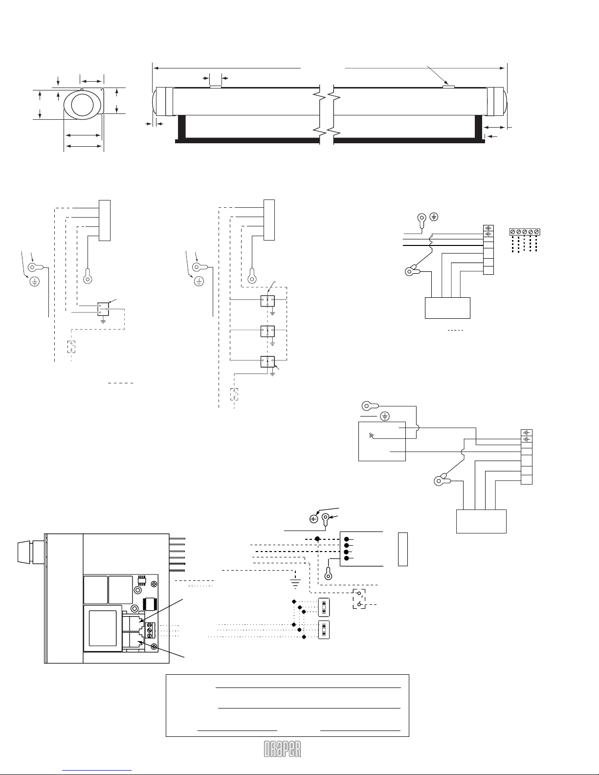
Single Station Control
Green/Yellow
To 110-120V Line
1
3
/8"
1
5
/16"
7
5
/16"
White
Black
Red
Green
Control
switch
Red
Blue
Location of key
operated on-off
switch if furnished
7
3
/16"
Motor
Single gang box by others
Min. 4" x 2
Black
Dashed wiring by others
Low Voltage & Remote Control
3
/8"
1
/8" x 1 7/8" deep
Salara—Dimensions
13/8"
Viewing Surface
Wiring Diagrams
Salara
Multiple Station Control
White
Black
Red
Motor
Chassis ground label
Screw attaching
endcap to case
Green/Yellow
Red
Green
To 110-120V Line
White-Common to screen & 110-120V AC Neutral
Red-to screen (directional)
Brown-to screen (directional)
Yellow-to 110-120V AC-Hot
Black-to 110-120V AC-Hot
Green(Ground)
Eye Port for IR Eye, RF Receiver or LED
Wall Switch. For more than one of
these, a splitter is required.
3 Button Wall Switch
DOWN - Black
COM - White
UP - Red
Aux Por t for connecting additional LVC-III
modules (up to six total can be linkedconnect from Aux to Eye).
Dashed wiring by electrician
Low voltage wiring by others
Blue
Black
Blue
Black
Blue
Black
Location of key
operated on-off
switch if furnished
Red
Red
Case Length
Cap off with wire
nut and tape
Dashed wiring
by electrician
Single gang box by others
1
Min. 4" x 2
3 shown. More or less equally
feasible.
/8" x 1 7/8" deep.
Green/Yellow
Internal Screen Wiring
STOP
STOP
Control
Switches
24v DC
Page 2 of 2
Floating Mounting Brackets
Hardwired with Built-in IR
See separate Serial Communication-RS232 Instruction
sheet for enabling RS232 with the MC1.
Chassis ground label
next to screw
Green
Motor
White
Red
Green
Black
TM
Green
L N Neu Dir Dir
Dashed Wiring
By Others
IR
Green
Black
White
White
Red
Black
Motor
MotorAC In
Green/Yellow
Black
White
(1) #10 Ring
Terminal on
each ground wire
Standard 110-120V AC IEC
(no external wiring necessary)
Green/Yellow
Chassis
ground
label
Chassis ground label
Screw attaching
endcap to case
Location of key
operated on-off
switch if furnished
Line 1
N
IEC Inlet
White (Common)
Red (Up)
Black (Down)
Green
(Motor Ground)
To
110-120V
Line
Plug & Play
Motor/PCB Ground
(1) #10 Ring
Terminal on
each ground wire
Motor
313/16"
5
/16"
RS232 Data from Control System
RS232 Data to Control System
Manual Up Switch
Signal Ground & Manual Switch Commo
Manual Down Switch
L N Neu Dir Dir
MotorAC In
PROJECT:
SUPPLIER:
DATE: REVISED:
www.draperinc.com
(765) 987-799
 Loading...