

Page 1
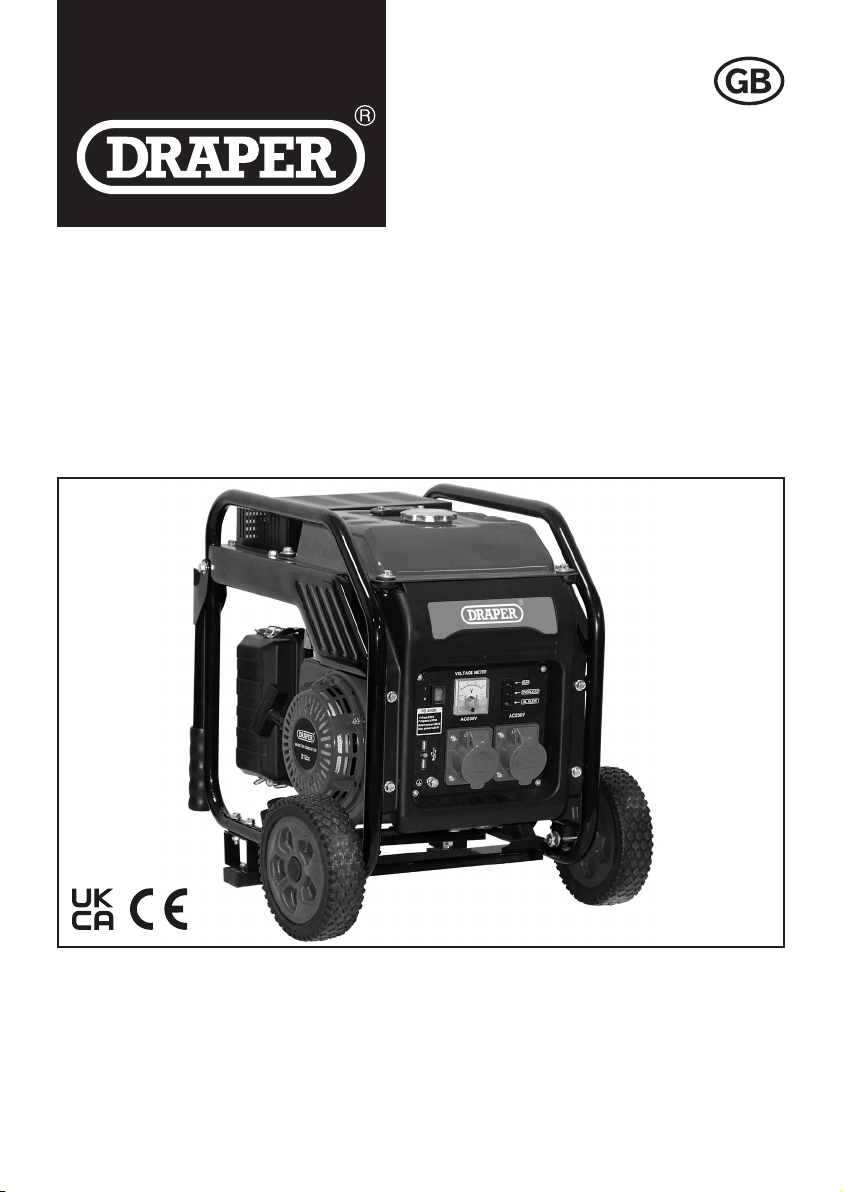
PETROL
INVERTER
GENERATOR
98683
These instructions accompanying the product are the original instructions. This document is part of the product, keep
it for the life of the product passing it on to any subsequent holder of the product. Read all these instructions before
assembling, operating or maintaining this product.
This manual has been compiled by Draper Tools describing the purpose for which the product has been designed,
and contains all the necessary information to ensure its correct and safe use. By following all the general safety
instructions contained in this manual, it will ensure both product and operator safety, together with longer life of the
product itself.
All photographs and drawings in this manual are supplied by Draper Tools to help illustrate the operation of the
product.
Whilst every effort has been made to ensure the accuracy of information contained in this manual, the Draper Tools
policy of continuous improvement determines the right to make modifications without prior warning.
Page 2

1. TITLE PAGE
1.1 INTRODUCTION:
USER MANUAL FOR: Petrol Inverter Generator
Stock No: 98683
Part No: PG4000
1.2 REVISIONS:
Date first published January 2021.
Date of first revision December 2022.
As our user manuals are continually updated, users should make
sure that they use the very latest version.
Downloads are available from: http://drapertools.com/manuals
Draper Tools Limited Draper Tools Limited
Hursley Road Oude Graaf 8
Chandler’s Ford 6002 NL
Eastleigh WEERT
Hampshire Netherlands
SO53 1YF
UK
Website: drapertools.com
Product Help Line: +44 (0) 23 8049 4344
General Fax: +44 (0) 23 8026 0784
1.3 UNDERSTANDING THIS MANUALS SAFETY CONTENT:
Warning! – Information that draws attention to the risk of injury or death.
Important – Information that draws attention to the risk of damage to the product or surroundings.
1.4 COPYRIGHT © NOTICE:
Copyright © Draper Tools Limited.
Permission is granted to reproduce this publication for personal and educational use only.
Commercial copying, redistribution, hiring or lending is prohibited.
No part of this publication may be stored in a retrieval system or transmitted in any other form or
means without written permission from Draper Tools Limited.
In all cases this copyright notice must remain intact.
– 2 –
Page 3

2. CONTENTS
2.1 TABLE OF CONTENTS
1. TITLE PAGE
1.1 INTRODUCTION: ......................... 2
1.2 REVISIONS: ................................. 2
1.3 UNDERSTANDING THIS
MANUALS SAFETY CONTENT: .. 2
1.4 COPYRIGHT © NOTICE: ............. 2
2. CONTENTS
2.1 TABLE OF CONTENTS ................ 3
3. WARRANTY
3.1 WARRANTY .................................4
4. INTRODUCTION
4.1 SCOPE ......................................... 5
4.2 SPECIFICATION .......................... 5
4.3 HANDLING AND STORAGE ........6
5. HEALTH AND SAFETY INFORMATION
5.1 GENERAL SAFETY
INSTRUCTIONS FOR POWER
TOOL USE .................................... 7
5.2 ADDITIONAL SAFETY
INSTRUCTIONS FOR
GENERATOR USE ....................... 8
5.3 RESIDUAL RISK...........................9
6. TECHNICAL DESCRIPTION
6.1 IDENTIFICATION – MAIN
FEATURES ................................. 10
6.2 IDENTIFICATION – SWITCH
PANEL ........................................ 11
7. UNPACKING AND CHECKING
7.1 PACKAGING ............................... 11
7.2 WHAT’S IN THE BOX ................. 11
8. ASSEMBLY
8.1 ATTACHING THE TRANSPORT
WHEELS ..................................... 12
8.2 ATTACHING THE
SUPPORT FEET .......................12
8.3 ATTACHING THE TRANSPORT
HANDLES ................................... 12
9. PREPARING THE GENERATOR
9.1 CONNECTING TO EARTH ........ 13
9.2 HANDLING & STORAGE ..........13
9.3 ADDING ENGINE OIL ................13
9.4 ADDING FUEL ............................ 14
10. OPERATING INSTRUCTIONS
10.1 PRE-OPERATIONAL
CHECKLIST ................................ 15
10.2 STARTING THE GENERATOR .. 15
10.3 STOPPING THE
GENERATOR ............................ 16
10.4 OVERLOAD CUT-OUT FOR
SOCKET-OUTLETS ...................16
10.5 AC APPLICATIONS .................... 16
10.6 DC POWER ................................ 17
10.7 INDICATOR LIGHTS ..................17
11. MAINTENANCE AND
TROUBLESHOOTING
11.1 THE IMPORTANCE OF
MAINTENANCE .......................... 18
11.2 MAINTENANCE SCHEDULE ..... 18
11.3 AIR CLEANER SERVICE ........... 19
11.4 SPARK PLUG ............................. 19
11.5 CHECKING OIL LEVEL &
CHANGING OIL .......................... 20
11.6 FUEL TANK FILTER ................... 20
11.7 TROUBLESHOOTING ................ 20
12. DISPOSAL
12.1 DISPOSAL .................................. 21
13. EXPLANATION OF SYMBOLS
13.1 EXPLANATION OF SYMBOLS .. 22
– 3 –
Page 4

3. WARRANTY
3.1 WARRANTY
Draper tools have been carefully tested and inspected before shipment and are guaranteed to be
free from defective materials and workmanship.
Should the tool develop a fault, please return the complete tool to your nearest distributor or
contact:
Draper Tools Limited, Chandler’s Ford, Eastleigh, Hampshire, SO53 1YF. England.
Telephone Sales Desk: +44 (0) 8049 4333 or Product Help Line +44 (0) 23 8049 4344.
A proof of purchase must be provided with the tool.
If upon inspection it is found that the fault occurring is due to defective materials or workmanship,
repairs will be carried out free of charge. This warranty period covering labour is 12 months from
the date of purchase except where tools are hired out when the warranty period is 90 days from
the date of purchase. The warranty is extended to 24 months for parts only. This warranty does not
apply to any consumable parts, any type of battery or normal wear and tear, nor does it cover any
damage caused by misuse, careless or unsafe handling, alterations, accidents, or repairs
attempted or made by any personnel other than the authorised Draper warranty repair agent.
Note: If the tool is found not to be within the terms of warranty, repairs and carriage charges will
be quoted and made accordingly.
This warranty applies in lieu of any other warranty expressed or implied and variations of its terms
are not authorised.
Your Draper warranty is not effective unless you can produce upon request a dated receipt or
invoice to verify your proof of purchase within the warranty period.
Please note that this warranty is an additional benefit and does not affect your statutory rights.
Draper Tools Limited.
– 4 –
Page 5

4. INTRODUCTION
4.1 SCOPE
This manual is intended to give an overview of the functioning and controls of the machine to aid
in its safe use.
4.2 SPECIFICATION
Stock No. .................................................................................................................................. 98683
Part No. ................................................................................................................................. PG4000
Engine type ............................................................................................................... Four cycle OHV
Displacement .............................................................................................................................212cc
Rated power ............................................................................................................................3800W
Rated current ................................................................................................................................ 16A
Max power ............................................................................................................................... 4000W
Cooling system ................................................................................................................... Forced air
Output sockets:
Rated AC .................................................................................................................... 2 × 230V
Rated AC frequency ..........................................................................................................50Hz
12V @ 5.0A (2 × 1.0A USB) ............................................................. DC 5V@2A(2×1.0A USB)
Performance class ......................................................................................................................... G1
Grade ................................................................................................................................................ A
Oil capacity .................................................................................................................................. 0.6L
Engine oil ....................................................................................................................... SAE 15W-40
Fuel tank capacity ........................................................................................................................ 5.0L
Fuel type .................................................................................................... Unleaded petrol (RON95)
Noise level 4M ....................................................................................................................... 96dB(A)
Uncertainty (K) ............................................................................................................... 3dB(A)
Altitude ..................................................................................................................................... 1000m
Max. ambient temperature .......................................................................................................... 40°C
Dimensions (L × W × H) ........................................................................................ 500 × 350 ×485mm
Weight .......................................................................................................... 28.5kg nett / 31kg gross
4.3 HANDLING AND STORAGE
Caution: Always use and store this generator correctly, never use or store this generator on it’s
– 5 –
Page 6

4. INTRODUCTION
side as oil or fuel may leak and damage the generator or your property.
If the generator has been used always allow it to cool for at least 30 minutes before transporting
the generator and ensure that the generator has fully cooled before returning it to storage as a hot
engine and exhaust system could cause personal injury or ignite some materials.
To prevent fuel/oil spillage when transporting, the generator should be secured upright in it’s
normal operating position with the engine switch in the off position.
Take care not to drop or strike the generator when transporting. Never cover the generator when in
use.
Before storing the generator for a long period:-
1. Be sure that the storage area is free of excessive humidity and dust.
2. Drain the fuel, storage procedure below.
A. Unscrew the fuel tank cap, remove the filter screen and empty the fuel tank into an
approved petrol container using a commercially available hand siphon (Draper Stock
No.43650), re-install the filter screen and fuel tank cap.
B. Loosen the carburettor drain screw and drain the carburettor into a suitable container.
C. Remove the spark plug maintenance cover and remove the spark plug cap.
D. Turn the engine switch to the OFF position.
– 6 –
Page 7

5. HEALTH AND SAFETY INFORMATION
5.1 GENERAL SAFETY INSTRUCTIONS FOR POWER TOOL USE
When using any type of power tool there are steps that should be taken to make sure that you, as
the user, remain safe.
Common sense and a respect for the tool will help reduce the risk of injury.
Read the instruction manual fully. Do not attempt any operation until you have read and
understood this manual.
Most important you must know how to safely start and stop this machine, especially in an
emergency.
Keep the work area tidy and clean. Attempting to clear clutter from around the machine during
use will reduce your concentration. Mess on the floor creates a trip hazard. Any liquid spilt on the
floor could result in you slipping.
Find a suitable location. If the machine is bench mounted, the location should provide good
natural light or artificial lighting as a replacement. Avoid damp and dust locations as it will have a
negative effect on the machine’s performance. If the machine is portable do not expose the tool to
rain. In all cases do not operate power tools near any flammable materials.
Keep bystanders away. Children, onlookers and passers by must be restricted from entering the
work area for their own protection. The barrier must extend a suitable distance from the tool user.
Unplug and house all power tools that are not in use. A power tool should never be left unattended
while connected to the power supply. They must be housed in a suitable location, away locked up
and from children. This includes battery chargers.
Do not overload or misuse the tool. All tools are designed for a purpose and are limited to what
they are capable of doing. Do not attempt to use a power tool (or adapt it in any way) for an
application it is not designed for. Select a tool appropriate for the size of the job. Overloading a tool
will result in tool failure and user injury. This covers the use of accessories.
Dress properly. Loose clothing, long hair and jewellery are all dangerous because they can
become entangled in moving machinery. This can also result in parts of body being pulled into the
machine. Clothing should be close fitted, with any long hair tired back and jewellery and neck ties
removed. Footwear must be fully enclosed and have a non-slip sole.
Wear personal protective equipment (PPE). Dust, noise, vibration and swarf can all be
dangerous if not suitably protected against. If the work involving the power tool creates dust or
fumes wear a dust mask. Vibration to the hand, caused by operating some tools for longer periods
must be protected against. Wear vibration reducing gloves and allow long breaks between uses.
Protect against dust and swarf by wearing approved safety goggles or a face shield. These are
some of the more common hazards and preventions, however, always find out what hazards are
associated with the machine/work process and wear the most suitable protective equipment
available.
Do not breathe contaminated air. If the work creates dust or fumes connect the machine (if
possible) to an extraction system either locally or remotely. Working outdoors can also help if
possible.
Move the machine as instructed. If the machine is hand held, do not carry it by the power supply
cable. If the product is heavy, employ a second or third person to help move it safely or use a
mechanical device. Always refer to the instructions for the correct method.
Do not overreach. Extending your body too far can result in a loss of balance and you falling. This
could be from a height or onto a machine and will result in injury.
Maintain your tools correctly. A well maintained tool will do the job safely. Replace any damaged
or missing parts immediately with original parts from the manufacturer. As applicable, keep blades
sharp, moving parts clean, oiled or greased, handles clean, and emergency devices working.
Wait for the machine to stop. Unless the machine is fitted with a safety brake, some parts may
continue to move due to momentum. Wait for all parts to stop, then unplug it from the power supply
– 7 –
Page 8

5. HEALTH AND SAFETY INFORMATION
before making any adjustments, carrying out maintenance operations or just finishing using the
tool.
Remove and check setting tools. Some machinery requires the use of additional tools or keys to
set, load or adjust the power tool. Before starting the power tool always check to make certain they
have been removed and are safely away from the machine.
Prevent unintentional starting. Before plugging any machine in to the power supply, make sure
the switch is in the OFF position. If the machine is portable, do not hold the machine near the
switch and take care when putting the machine down, that nothing can operate the switch.
Carefully select an extension lead. Some machines are not suitable for use with extension
leads. If the tool is designed for use outdoors, use an extension lead also suitable for that
environment. When using an extended lead, select one capable of handling the current (amps)
drawn by the machine in use. Fully extend the lead regardless of the distance between the power
supply and the tool. Excess current (amps) and a coiled extension lead will both cause the cable to
heat up and can result in fire.
Concentrate and stay alert. Distractions are likely to cause an accident. Never operate a power
tool if you are under the influence of drugs (prescription or otherwise), including alcohol or if you
are feeling tired. Being disorientated will result in an accident.
Have this tool repaired by a qualified person. This tool is designed to conform to the relevant
international and local standards and as such should be maintained and repaired by someone
qualified, using only original parts supplied by the manufacturer. This will ensure the tool remains
safe to use.
5.2 ADDITIONAL SAFETY INSTRUCTIONS FOR GENERATOR USE
Note: Generators are designed to give safe and dependable service if operated according to
instructions. Read and understand this owners manual fully before operating this generator. You
can help prevent accidents by being familiar with the generators controls and by observing safe
operating procedures.
Operator responsibility
– Know how to stop the generator quickly in case of emergency.
– Understand the use of all the generators controls, output sockets and connections.
– Be sure that anyone who operates the generator receives proper instruction in it’s safe use.
Warning! Carbon monoxide hazards
– Exhaust gases contain poisonous carbon monoxide, a colourless and odourless gas.
– Breathing carbon monoxide can cause loss of consciousness and may lead to death.
NEVER run this generator in an enclosed space or partly enclosed space.
ALWAYS ensure a high level of ventilation in the area that you intend to use the generator to avoid
the potential build up of carbon monoxide.
Warning! Electric shock hazards
– The generator produces enough electric power to cause a serious shock or electrocution if
misused.
– Using a generator or electrical appliance in wet conditions, such as rain or snow, or near a pool
or sprinkler system, or when your hands are wet, could result in electrocution. Keep the
generator dry.
– If the generator is stored outdoors, unprotected from the weather, check all of the electrical
components on the control panel before each use. Moisture or ice can cause a malfunction or
short circuit in electrical components which could result in electrocution.
– Do not connect to a building electrical system unless an isolation switch has been installed by a
qualified electrician.
– Never connect different generator models and types.
– 8 –
Page 9

5. HEALTH AND SAFETY INFORMATION
Warning! Fire and burn hazards
– The exhaust system gets hot enough to ignite some materials.
– Keep the generator at least 3 feet (1 metre) away from buildings and other equipment during
operation.
– Do not enclose the generator in any structure.
– Keep flammable materials away from the generator.
– The muffler becomes very hot during operation and remains hot for a while after stopping the
engine. Be careful not to touch the muffler while it is hot. Let the engine cool before storing the
generator indoors.
– Petrol is extremely flammable and is explosive under certain conditions. Do not smoke or allow
flames or sparks where the generator is refuelled or where petrol is stored. Refuel in a well-
ventilated area with the engine stopped.
– Fuel vapours are extremely flammable and may ignite after the engine has started. Make sure
that any spilled fuel has been wiped up before starting the generator.
5.3 RESIDUAL RISK
Important: Although the safety instructions and operating manuals for our tools contain extensive
instructions of safe working with power tools, every power tool involves a certain residual risk
which can not be completely excluded by safety mechanisms. Power tools must therefore always
be operated with caution!
– 9 –
Page 10
6. TECHNICAL DESCRIPTION
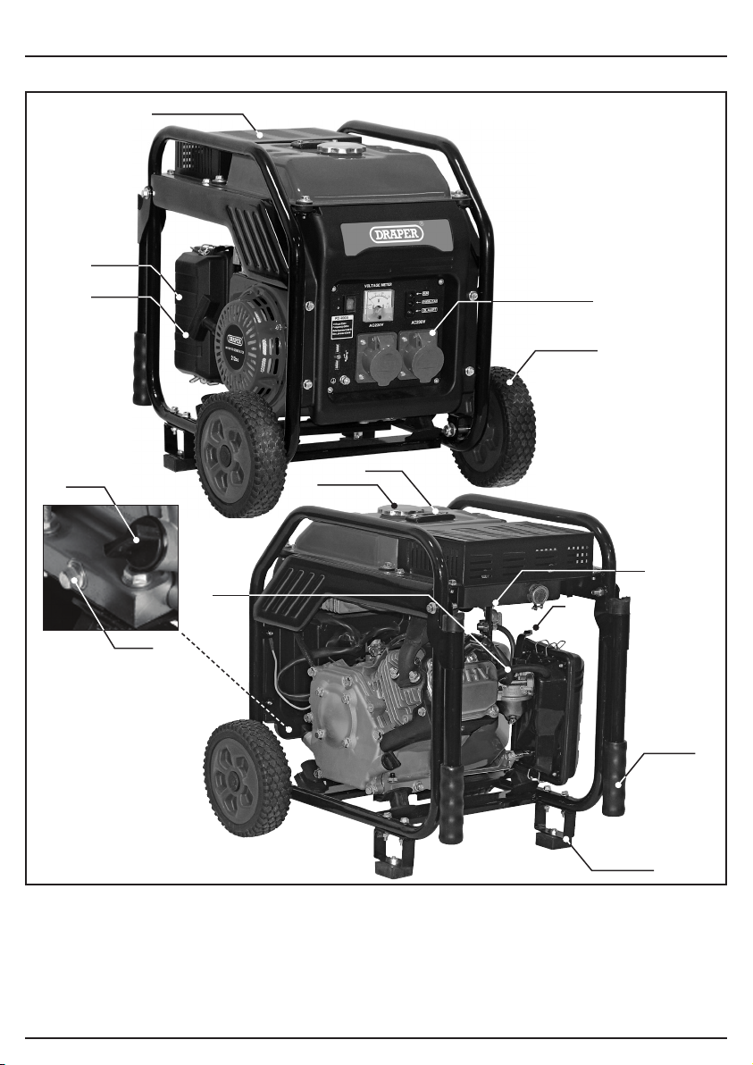
6.1 IDENTIFICATION – MAIN FEATURES
(7)
(3)
(10)
(4)
(11)
(12)
(1)
(13)
(8)
(9)
(14)
(5)
(6)
(1) 230V AC socket outlets.
(2) Support feet.
(3) Air filter.
(4) Pull cord.
(5) Choke lever.
(6) Transport handles.
(7) Radiator plate
(8) Fuel level Indicator
(9) Fuel cap.
(10) Oil filler cap/dipstick.
– 10 –
(2)
(11) Oil drain plug.
(12) Spark plug cable.
(14) Fuel cock.
Page 11
6. TECHNICAL DESCRIPTION
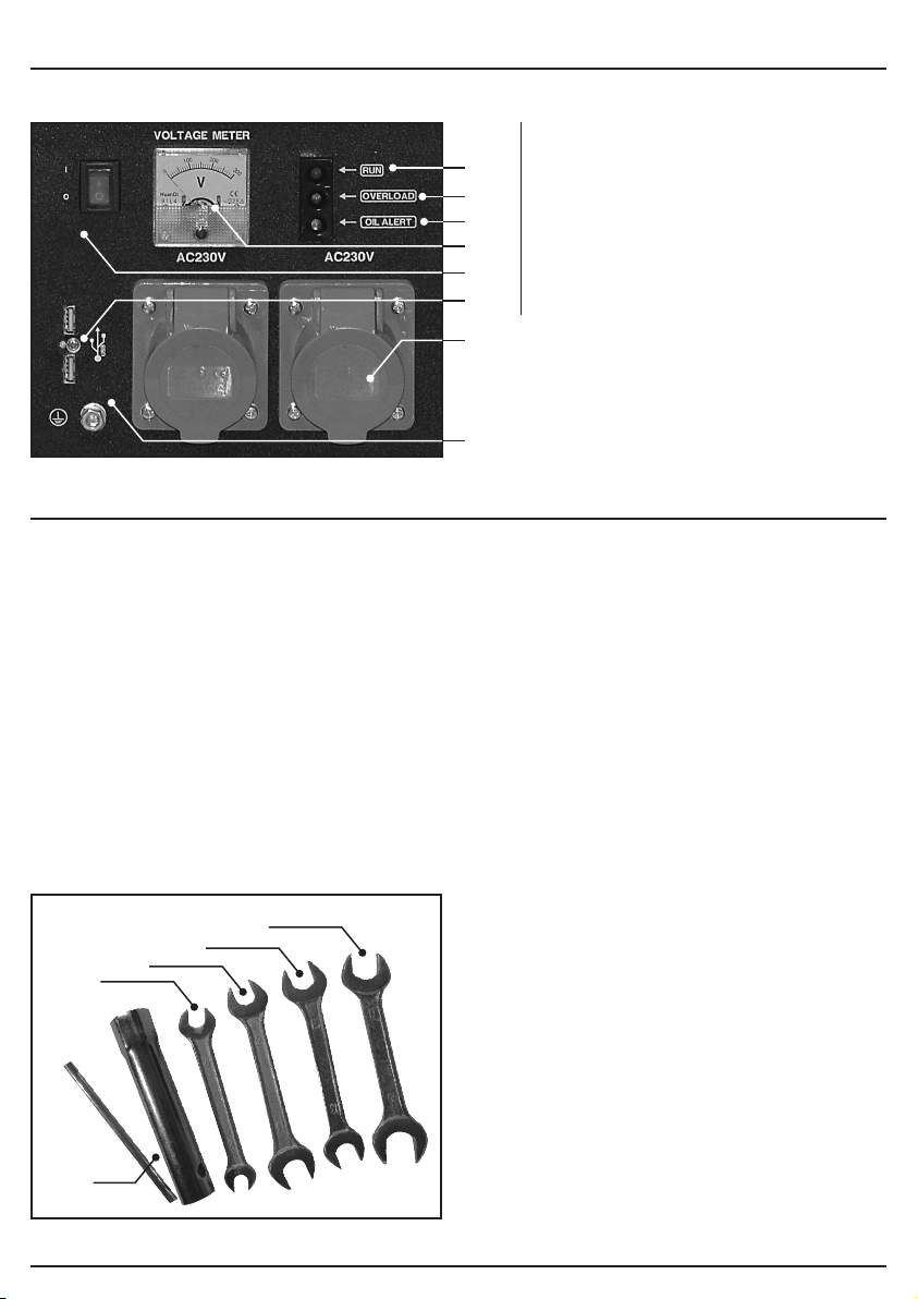
6.2 IDENTIFICATION – SWITCH PANEL
(1) 230V AC socket outlets.
(18)
(19)
(20)
(21)
(15)
(17)
(1)
(16)
(15) ON/OFF switch.
(16) Earthing point.
(17) 12V DC/USB outlets.
(18) Operational light.
(19) Overload warning light.
(20) Oil pressure warning light.
(21) Voltage meter.
7. UNPACKING AND CHECKING
7.1 PACKAGING
Carefully remove the product from the packaging and examine it for any sign of damage that may
have happened during shipping. Lay the contents out and check them against the parts shown
below. If any part is damaged or missing, please contact the Draper Help Line (the telephone
number appears on the Title page) and do not attempt to use the product.
The packaging material should be retained at least during the warranty period, in case the
machine needs to be returned for repair.
Warning!
− Some of the packaging materials used may be harmful to children. Do not leave any of these
materials in the reach of children.
− If any of the packaging is to be thrown away, make sure they are disposed of correctly,
according to local regulations.
7.2 WHAT’S IN THE BOX
As well as the main product, there are several parts not fitted or attached to it.
(23)
(22)
(24)
(25)
(26)
(22) Spark plug box spanner.
(23) 8 × 10mm Open ended spanner.
(24) 12 × 14mm Open ended spanner.
(25) 13 × 15mm Open ended spanner.
(26) 17 × 19mm Open ended spanner.
Note: For details of our full range of
accessories and consumables,
please visit drapertools.com
– 11 –
Page 12
8. ASSEMBLY
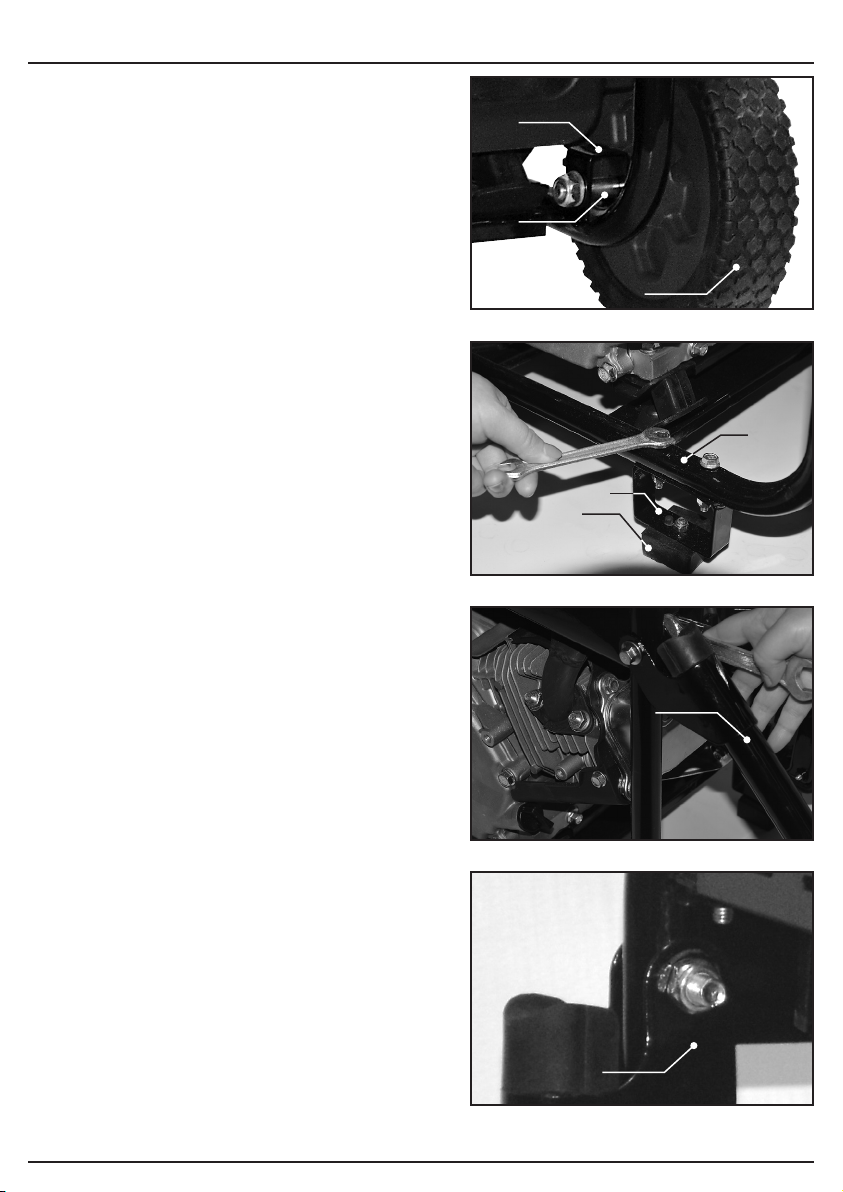
8.1 ATTACHING THE TRANSPORT
WHEELS – FIG.1
Note: The wheels are not intended for on-road
use.
− Slide the wheel axle (13.2)through the holes in
the wheel brackets (13.1)mounted on the
frame.
− Use the supplied fixings in conjunction with the
appropriate sized supplied spanner (23)–
to secure the wheel in place.
− Repeat the above steps with the other transport
wheel.
8.2 ATTACHING THE SUPPORT FEET
– FIG.2
Using the photograph shown in FIG.2 for
reference:
− Attach the rubberised foot (2.1)to the foot
support bracket (2.2)using the supplied fixings.
− Align the assembled foot support with the holes
in the lower framework (2.3).
− Tighten the support foot to the frame using the
appropriate sized spanner supplied
− Repeat the above steps to assemble the other
support foot.
8.3 ATTACHING THE TRANSPORT
HANDLES – FIGS.3 – 4
Using the photographs shown in FIGS.2 – 3 for
reference:
− Align the support handles (6)with the
corresponding holes located on generator
frame
− Secure in place using the appropriate fixings
and the appropriate sized spanner supplied
(23)– (26).
(26)
(23)– (26).
(13.1)
(13.2)
FIG.
FIG.
FIG.
(13)
1
(2.3)
(2.2)
(2.1)
2
(6)
3
– 12 –
FIG.
(6)
4
Page 13
9. PREPARING THE GENERATOR
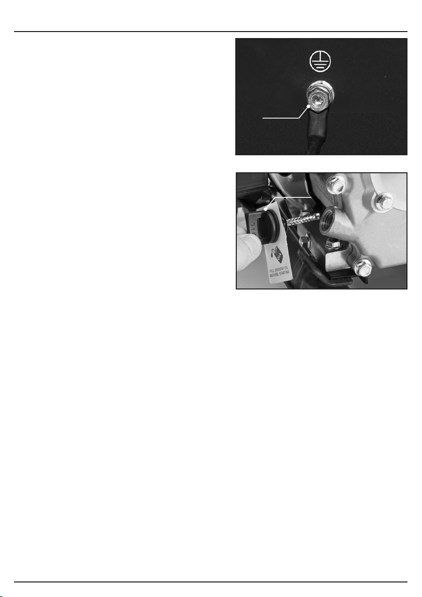
9.1 CONNECTING TO EARTH – FIG.5
The generator must be earthed to discharge static
electricity. Attach a cable to the connection (16) on
the faceplate, the other end to external earth (for
example an earth rod which can be purchased at
your local camping supplier).
Earthing of generators is covered in BS7430:2011.
If you have any doubts about this subject consult a
qualified electrician.
9.2 HANDLING & STORAGE
Warning! Petrol is highly flammable and explosive.
You can be burned or seriously injured when
handling fuel.
• Keep heat, sparks and flame away.
• Handle fuel outdoors only.
• Wipe up spills immediately.
If storing this machine for a prolonged time there
are some procedures to follow to prepare the
machine prior to storage:
− Remove any fuel from the fuel tank by using a
siphon. Loosen the carburettor drain screw and
drain remaining fuel into a suitable container
prior to correct disposal of old fuel (check local
regulations).
− Check the machine over and repair or replace any worn or damaged parts.
− Remove the spark plug and pour about a tablespoon of clean engine oil into the cylinder.
− Crank the engine several revolutions to distribute the oil, then re-install the spark plug.
− Re-install the spark plug cap on the spark plug securely.
− Pull the starter grip slowly until you feel resistance, then return the starter grip gently. This
closes the valves so moisture cannot enter.
Warning! The generator is shipped without oil in the engine. You MUST add the required amount
of oil before trying to start the engine.
9.3 ADDING ENGINE OIL – FIG. 6
− With the generator on a level surface, remove the oil filler cap/dipstick (10).
− Add exactly: 0.6L (15W-40 SAE 40).
Warning! Do not overfill the engine with oil
If the engine is overfilled, the excess oil may be transferred to and contaminate the air filter and it’s
housing.
− Screw in the filler cap/dipstick (16)securely.
Caution: prolonged exposure to used engine oil is dangerous, always wash your hands
thoroughly after handling used engine oil.
Environmental protection
One of the most damaging sources of pollution is oil. Do not throw away used engine oil in with
your domestic waste or down drains and sinks. Place it in a leak proof container and dispose of it
according to local regulations.
(16)
5 FIG.
(10)
6 FIG.
– 13 –
– 13 –
Page 14

9. PREPARING THE GENERATOR
9.4 ADDING FUEL – FIG.5
− Remove fuel cap (9) fill with unleaded petrol
(RON95), do not over fill, allow room for fuel
expand when it heats up. Replace cap.
− Never use stale or contaminated petrol or an
oil/petrol mixture. Avoid getting dirt or water in
the fuel tank.
− If the fuel level is low, refuel in a well-ventilated
area with the engine stopped.
− If the engine has been running, allow it to cool
first.
Warning! Never refuel the engine inside a building
where petrol fumes can reach flames or sparks.
Warning! Petrol is highly flammable and explosive.
You can be burned or seriously injured when handling fuel.
• Stop the engine and keep heat, sparks and flames away.
• Handle fuel only outdoors.
• Wipe up spills immediately.
7 FIG.
(9)
– 14 –
Page 15
10. OPERATING INSTRUCTIONS
10.1 PRE-OPERATIONAL CHECKLIST
Before starting the generator:
− You MUST fill up with engine oil and fuel before
you can start the engine.
− Check the fuel level and top it up if necessary.
− Make sure that the generator has sufficient
ventilation.
− Make sure that the ignition cable is secured to
the spark plug.
− Inspect the immediate vicinity of the generator.
− Disconnect any electrical equipment which may
already been connected to the generator.
− Permissible ambient temperature -10 to 40°C,
max. altitude above sea level 1000M.
Warning! For your safety DO NOT operate the
generator in an enclosed area such as a garage.
The generator’s exhaust emits toxic gases
containing poisonous carbon monoxide which can
cause unconsciousness and even death in high
concentrations.
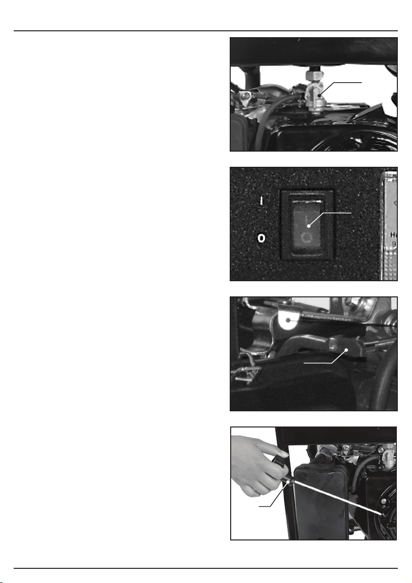
10.2 STARTING THE GENERATOR –
FIGS. 8 – 11
Note: Before connecting loads/appliances to the
generator, be sure to read the chapters on AC
OPERATION and DC OPERATION that follow this
section.
Note: Prior to each starting of the machine,
perform the pre-operational checklist above.
− Open the fuel cock (14) by turning it down.
− Turn the engine switch (15) to the “ON”
position.
− Move the choke lever (5) to the “CHOKE”
position to start the engine from cold.
Note: The choke is not required to start a warm
engine.
− Pull the starter cord (4) gently until you feel
resistance then give a brisk pull on the starter
cord, several pulls on the starter cord may be
required to start the engine.
Note: Do not allow the extended starter cord to
snap back against the engine casing as damage to
the starter or housing can occur.
− If the choke lever was moved to the “CHOKE”
position to start the engine from cold, gradually
move it to the “Run” position as the engine
warms up.
FIG.
FIG.
FIG.
(14)
8
(15)
9
(5)
10
(4)
– 15 –
FIG.
11
Page 16
10. OPERATING INSTRUCTIONS
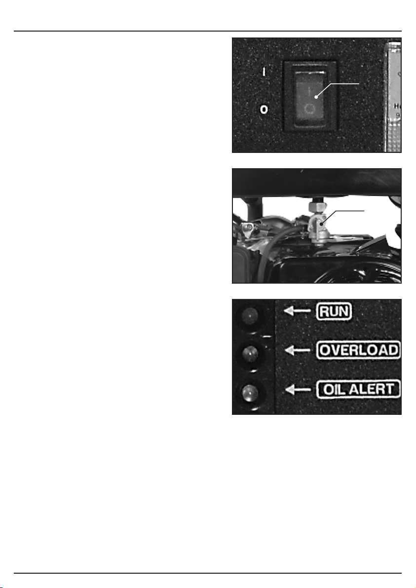
10.3 STOPPING THE GENERATOR –
FIGS.12 – 13
To stop the engine in an emergency, switch the
engine on/off switch to off.
Under normal operating conditions, use the
procedure detailed below to stop the generator:-
− Unplug any appliances and/or charging batteries
from the generator, if the generator has been
working hard allow it to idle for a short time.
− Switch the engine ON/OFF switch (15) to off.
− Turn fuel cock off (14).
− Allow the engine to fully cool before transporting
or returning to storage.
FIG.
12
10.4 OVERLOAD CUT-OUT FOR
SOCKET-OUTLETS – FIG.14
Important: The generator is equipped with an
electronic overload protection which switches off
the sockets in case of overload.
When the overload cut-off is displayed, turn off the
power generator and remove the connected
equipment from the generator. This will reset the
overload cut-off and allow you to turn the generator
back on.
Important: If this happens, reduce the electric
power you are taking from the generator or remove
any defective connected appliances.
Important: Defective overload cut-outs must be
replaced only by overload cut-outs of identical
design and with the same performance data. If
repairs are necessary, please contact your
customer service centre.
FIG.
13
10.5 AC APPLICATIONS
Before connecting an appliance or power cord to
the generator:-
Note: Allow 2-3 minutes after starting the generator
to allow the generator to settle before connecting
AC appliances and using the throttle economy
switch.
1. Make sure that it is in good working order. Faulty appliances or power cords can create the
potential for electric shock.
2. If an appliance begins to operate abnormally in any way, turn it off immediately and disconnect
it from the generator and check that the appliance does not exceed the generators maximum
rating.
Always make sure that the appliances power rating does not exceed the generator’s maximum
rating.
In either case the total power requirements (VA) of all appliances connected must be considered.
The above limits must not be exceeded.
FIG.
14
(15)
(14)
– 16 –
Page 17
10. OPERATING INSTRUCTIONS
When powering sensitive electronics it is advisable
to only power a single appliance at a time.
Note: Substantial overloading will switch off the
engine. Exceeding the limits for maximum power
operation or slightly overloading the generator may
not switch off the generator but will shorten the
service life of the generator.
The AC output is Pure Sine Wave so it’s safe for
sensitive appliances such as laptops or appliances
with a digital panel. It can also power induction
plates and microwave ovens.
10.6 DC POWER
− Set the economy control switch to ‘OFF’.
− Start the generator.
− Make sure the appliance is turned off before connecting it to the generator.
− Connect the 12V appliance (max. 4A) to the generator.
FIG.
15
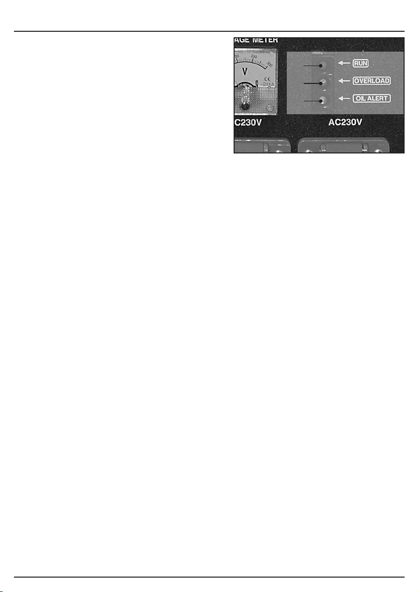
10.7 INDICATOR LIGHTS – FIG. 15
RUN indicator (18) (Green) will remain on during normal operation.
OVERLOAD indicator (19) (Red) will light up if there is an overload or a short circuit in the
connected appliance.
If this happens, proceed as follows:
− Turn off any connected electrical devices and stop the engine.
− Reduce the total wattage of connected electric devices to within the rated output of the
generator.
− Check air inlet and around the control unit. If any blockages are found, remove them.
− After checking, restart the engine.
OIL ALERT indicator (20)
The oil alert indicator (Red) will light up when the oil level is low.
(18)
(19)
(20)
– 17 –
Page 18

11. MAINTENANCE AND TROUBLESHOOTING
11.1 THE IMPORTANCE OF MAINTENANCE
Good maintenance is essential for the safe, economical and trouble-free operation of the
generator. It will also help reduce air pollution.
Warning!Improper maintenance, or failure to correct a problem before operation, can cause a
malfunction in which could cause serious injury or death.
Always follow the inspection and maintenance recommendations and schedules in this owner’s
manual.
To help you to properly care for your generator, the following pages include a maintenance
schedule, routine inspection procedures and simple maintenance procedures using basic hand
tools. Other service tasks that are more difficult, or require special tools, are best handled by
professionals and are normally performed by a technician or other qualified mechanic.
The maintenance schedule applies to normal operating conditions. If you operate your generator
under severe conditions, such as sustained high-load or high temperature operation, or use it in
usually wet or dusty conditions, consult your servicing dealer for recommendations applicable to
your individual needs and use.
Remember that your servicing dealer knows your generator best and is fully equipped to maintain
and repair it. To ensure the best quality and reliability, use only new, genuine Draper parts for
repair or replacement.
11.2 MAINTENANCE SCHEDULE
Regular service period Before
Item
Perform at every indicated month or
operating hour interval, whichever
comes first.
Engine oil Check level
Change
Air cleaner Check
Clean
Spark plug Check/adjust
Replace
Spark arrester Clean
Valve clearance Check/adjust
Combustion camber Clean After every 300 hrs. (2)
Fuel tank and filter Clean ● (2)
Fuel line Check Every 2 years (replace if necessary) (2)
(1) Service more frequently when used in dusty areas.
(2) These items should be serviced by your servicing dealer, unless the owner has the proper tools
and is mechanically proficient. Failure to follow this maintenance schedule could result in
non-warrantable failures.
each
use
●
●
– 18 –
First
month
or 20
hours
● ●
Every
3
months
or 50
hours
● (1)
●
Every
6
months
or 100
hours
●
●
Every
2 years
or 300
hours
● (2)
Page 19
11. MAINTENANCE AND TROUBLESHOOTING
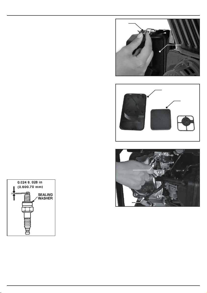
11.3 AIR CLEANER SERVICE –
FIGS. 16 – 17
A dirty air cleaner will restrict air flow to the
carburettor. To prevent carburettor malfunction,
service the air cleaner regularly. Service more
frequently when operating the generator in
extremely dusty areas.
Caution! Operating the engine without an air filter
or with a damaged air filter will allow dirt to enter
the engine, causing rapid engine wear.
This type of damage is not covered by the Draper
warranty.
− Remove the air filter housing cover (3.1) by
firstly pulling away the retaining clips (3.2).
− Remove the air filter element (3.3).
Warning! Using petrol or flammable solvent to
clean the air filter can cause a fire or explosion.
− Use only soapy water or non-flammable
solvent, once it is completely dry immerse the
filter in clean engine oil and squeeze the filter to
remove excess oil.
11.4 SPARK PLUG – FIG. 18
Remove and check spark plug for dirt and grime
and if necessary clean with a copper wire brush.
− Twist off the spark plug boot and cable (12).
− Using the spark plug ‘box’ spanner (22)
supplied, remove the spark plug.
− Check the spark plug gap with a feeler gauge, it
should be between 0.6 and 0.7 mm.
(3.2)
FIG.
FIG.
(3.1)
16
(3.1)
(3.3)
17
(22)
– 19 –
(12)
18 FIG.
Page 20
11. MAINTENANCE AND TROUBLESHOOTING
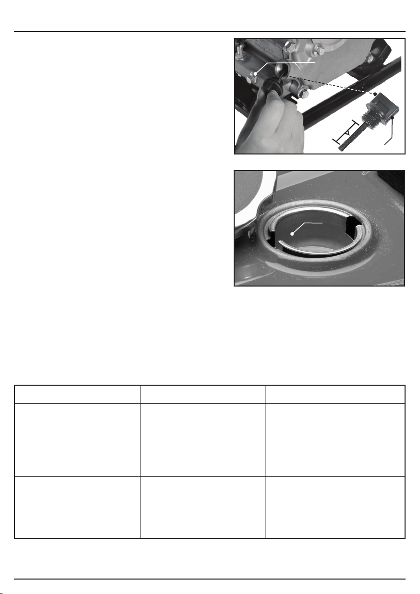
11.5 CHECKING OIL LEVEL &
CHANGING OIL – FIG.18
− Place the generator on a slightly inclined
surface so that the dip stick is at proper
position.
− Screw off the oil filler plug and wipe away any
oil on the dip stick.
− Put the oil dip stick back without screwing into
the oil filler.
Important: Do not screw the dipstick in to check
the oil level – simply insert it up to the thread.
− Check the dip stick; make sure the oil level is
between ‘high’ and ‘low’ marks, as shown in
Fig.18.
Changing the engine oil
See also
The motor oil is best changed when the motor is at
working temperature.
page 13:
− Only use motor oil (15W-40 SAE 40).
− Place the generator on a slightly inclined
surface so that the oil drain plug is at the lower
end.
− Open the oil filler plug (10).
− Open the oil drain plug (11) and let the hot
engine oil drain out into a drip tray.
− After the old oil has drained out, close the oil drain plug and place the generator on a level
surface again.
Section
9.3 ADDING ENGINE OIL
FIG.
FIG.
19
(1)
20
11.6 FUEL TANK FILTER – FIG.19
− Remove the fuel cap (9) and lift out the filter (9.1) – clean the filter with solvent.
11.7 TROUBLESHOOTING
(11)
HIGH
LOW
(9.1)
(10)
(2)
Fault Cause Remedy
Engine does not start
Generator has too little or
no voltage
− Oil shortage cut-out has
not responded
− Spark plug fouled
− No fuel
− Controller or capacitor
defective
− Overload cut-off has
triggered
− Air filter dirty
– 20 –
− Check oil level, top up
engine oil
− Clean or replace spark plug
(electrode spacing 0.6-0.7
mm)
− Refuel / check the fuel cock
− Contact your dealer
− Actuate the circuit-breaker
and reduce the consumers
− Clean or replace the filter
Page 21

12. DISPOSAL
12.1 DISPOSAL
– At the end of the machine’s working life, or when it can no longer be repaired, ensure that it is
disposed of according to national regulations.
– Contact your local authority for details of collection schemes in your area.
In all circumstances:
• Do not dispose of power tools with domestic waste.
• Do not incinerate.
• Do not dispose of WEEE* as unsorted municipal waste.
* Waste Electrical & Electronic Equipment.
– 21 –
Page 22

13. EXPLANATION OF SYMBOLS
13.1 EXPLANATION OF SYMBOLS
Read the instruction manual.
Wear ear defenders.
Do not abandon into the
environment.
Keep out of the reach of children.
Warning!
Warning!
Flammable material.
Warning!
Very hot surfaces.
Keep your distance.
Must be earthed.
WEEE –
Waste Electrical & Electronic Equipment.
Do not dispose of Waste Electrical & Electronic
Equipment in with domestic rubbish.
Continuous A-Weighted Sound
Pressure Level.
UK Conformity Assessed.
European conformity.
Warning!
Risk of electrocution.
Warning!
Risk of toxic fumes.
Do not operate the machine
indoors.
Do not connect to socket outlets
when performing maintenance.
Do not operate the machine
without essential lubricating oil.
– 22 –
Page 23

NOTES
– 23 –
Page 24

CONTACTS
Draper Tools Limited
UK: Hursley Road, Chandler’s Ford, Eastleigh,
Hampshire. SO53 1YF. U.K.
EU: Oude Graaf 8,
6002 NL, Weert (NL).
Help Line: (023) 8049 4344
Sales Desk: (023) 8049 4333
Internet: drapertools.com
E-mail: [email protected]
General Enquiries: (023) 8026 6355
Service/Warranty Repair Agent:
For aftersales servicing or warranty repairs, please contact the
Draper Tools Help Line for details of an agent in your local area.
YOUR DRAPER STOCKIST
RDCH1222
©Published by Draper Tools Limited.
No part of this publication may be reproduced, stored in a retrieval system or transmitted in any form or by any means,
electronic, mechanical photocopying, recording or otherwise without prior permission in writing from Draper Tools Ltd.
 Loading...