

Page 1
220-240V LVC-IV Low-Voltage Control Module
Low-Voltage wiring by others
Factory wiring
DASHED WIRING BY ELECTRICIAN
WIRING
INSTRUCTIONS
Section 1 - Overview
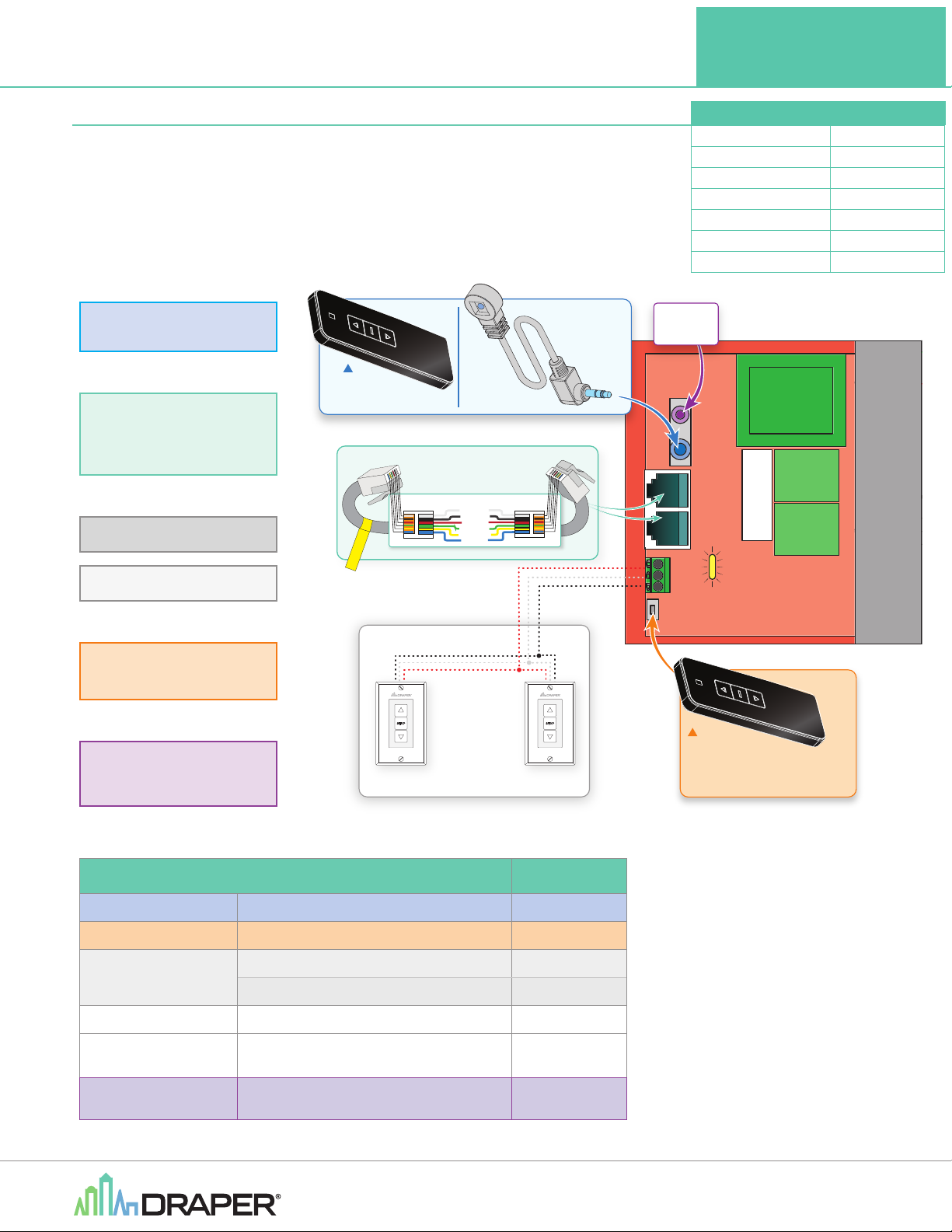
The LVC-IV module contains a 3-screw terminal block for a low-voltage wall switch,
an IR receiver jack, a built-in RF receiver, two-RJ25 ports for RS232 / RS485,
a low-voltage relay port with cable and a user-serviceable 3.5 Amp fuse.
Compatible components for each are listed below.
Uses
IR (Infrared)
IR Eye
Remote Control
IR Transmitter
Part#: 121227
Transmitter range: 26’ (7.9M)
RJ25 Ports for
RS-232/RS-485
Communication
Low-Voltage Wall Switch
NOTICE: Remove this test
lead before installation.
RJ25
Connector
RS232/485
Inputs/Outputs
(Ports are identical)
ELECTRICALLY STRAIGHT DATA CABLE
6 - WHITE - 6
5 - BLACK - 5
4 - RED - 4
3 - GREEN - 3
2 - YELLOW - 2
1 - BLUE - 1
RJ25
Connector
“Dry” Contact Closure
Dry Contact Closure
IR Eye
Input
Technical Specifications:
Power Supply: 230V / 50Hz
Temperature: -40° C – 85° C
Frequency: 433 MHz
Power: <300W
Transmit Power: <10mW
Sensitivity: -110dBm
Fuse: 3.15 Amp
Low Voltage
Trigger
4-28 VDC
250 VAC 5x20mm
FUSE - 3.15 AMP
SIGNAL LED
RF RECEIVER
BUTTON
LVC-IV
RF (Radio Frequency)
Remote Control
3rd Party Control
Control systems employing “dry”
contacts or Serial Communication.
The 230V LVC-IV also used as a Single-Pole, Double-Throw dry closure to control equipment by the same means listed above.
COMPATIBLE COMPONENTS PART NO.
IRT / R Infrared Remote Control (Connects to IR Port)
WRT / R Radio Frequency Remote (antenna built in)
LVC-S
KS-1 Power Supply Key Switch.
SP-KSM
Auxillary Control
Low-Voltage
Wall Switch(es)
SWITCH A
LVC-S: 3 Button Wall Switch(es) Part #: 121225
Low-Voltage Wall Switch.
Low-Voltage Wall Switch w/ Locking Cover
3-position Momentary Key Switch
(Please Note: 'Stop' won’t work)
Control systems employing “dry” contacts
or Serial Communication.
SWITCH B
121228
121226
121225
121232
121017
121022
By Others
Radio Frequency
(RF) Transmitter Part#: 121226
Operating range is 250’ (76M) open distance.
Each time the RF signal penetrates a wall,
distance will fall off 50%.
If you encounter any difficulties installing or servicing
your LVC-IV, call your dealer or contact Draper, Inc.
Draper, Inc. | 411 S. Pearl St. Spiceland, IN 47385
draperinc.com | 765.987.7999 | 800.238.7999
© 2021 All Rights Reserved | FORM: LVCIV_220_Wiring21
Page 2
220-240V LVC-IV Low-Voltage Control Module
RF Transmitter
Operating range is 250 feet (open distance). Each time
the RF signal penetrates a wall, distance will fall off 50%.
IR Transmitter
Transmitter range: 26’ (7.9M)
Section 2 - Programming Radio Frequency (RF) Remote Control
The LVC-IV comes with built-in Radio Frequency Remote control capability (optional handheld transmitter NOT included).
page 2 of 4
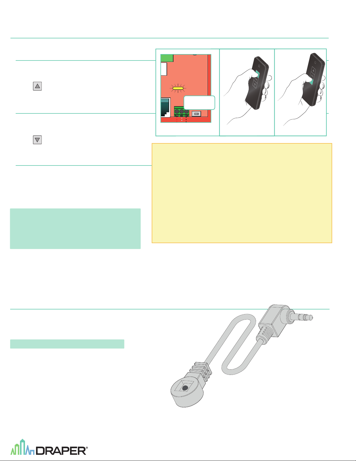
To "Learn" a remote
1.
Press receiver button on LVC-IV (see Fig. 2A).
2.
Signal light will flash slowly.
3.
Press
4.
Signal light flashes three times quickly.
(UP) on transmitter within 10 seconds (see Fig. 2B).
To "Un-Learn" a remote
1.
Press receiver button on LVC-IV (see Fig. 2A).
2.
Signal light will flash slowly.
3.
Press
4.
Signal light flashes three times quickly.
(DOWN) on transmitter within 10 seconds (see Fig. 2C).
To "Un-Learn" all remotes
1.
Press receiver button on LVC-IV until signal light flashes quickly,
then release.
2.
Press receiver button once while signal light is flashing.
3.
Signal light will stop flashing.
Please Note: Operating range is 250ft (76 meters) open distance.
RF Signal will degrade significantly with each wall
it is required to penetrate.
If you are experiencing issues with RF signal
strength, the RF antenna can be threaded out
one of the knockouts for better reception.
Figure 2
SIGNAL LED
Receiver
Button
.
CBA
PLEASE NOTE:
1. RF receiver MUST NOT TOUCH METAL OBJECTS!
Maximum Distance of Transmitter will be affected negatively.
2. Disconnect the power supply before installing the RF receiver.
3. Avoid electrostatic interference:
Static electricity will damage the electronic components.
4. Ensure there is > 5' (1.52M) between RF receiver and ground.
5. Ensure there is > 1' (30.5cm) between RF receiver and ceiling.
6. Ensure there is > 1' (30.5cm) between RF receiver and transmitter.
7. Multiple receivers must be spaced > 8" (20cm) apart.
Section 3 - Infrared (IR) Remote Control
1.
Plug Optional IR Eye into mini plug input provided on LVC-IV (see Figs. 1 and 3).
2.
IR Remote Control transmitter does not need to be "learned" by the LVC-IV. Simply point and operate.
3.
Maximum IR Eye cable length is 42" (1 meter).
Please Note: IR Transmitter Range is 26ft. (7.9 meters).
Figure 3
Page 3
FUSE - 3.15 AMP
250 VAC 5x20mm
220-240V LVC-IV Low-Voltage Control Module
Section 4 - DC Low-voltage Trigger
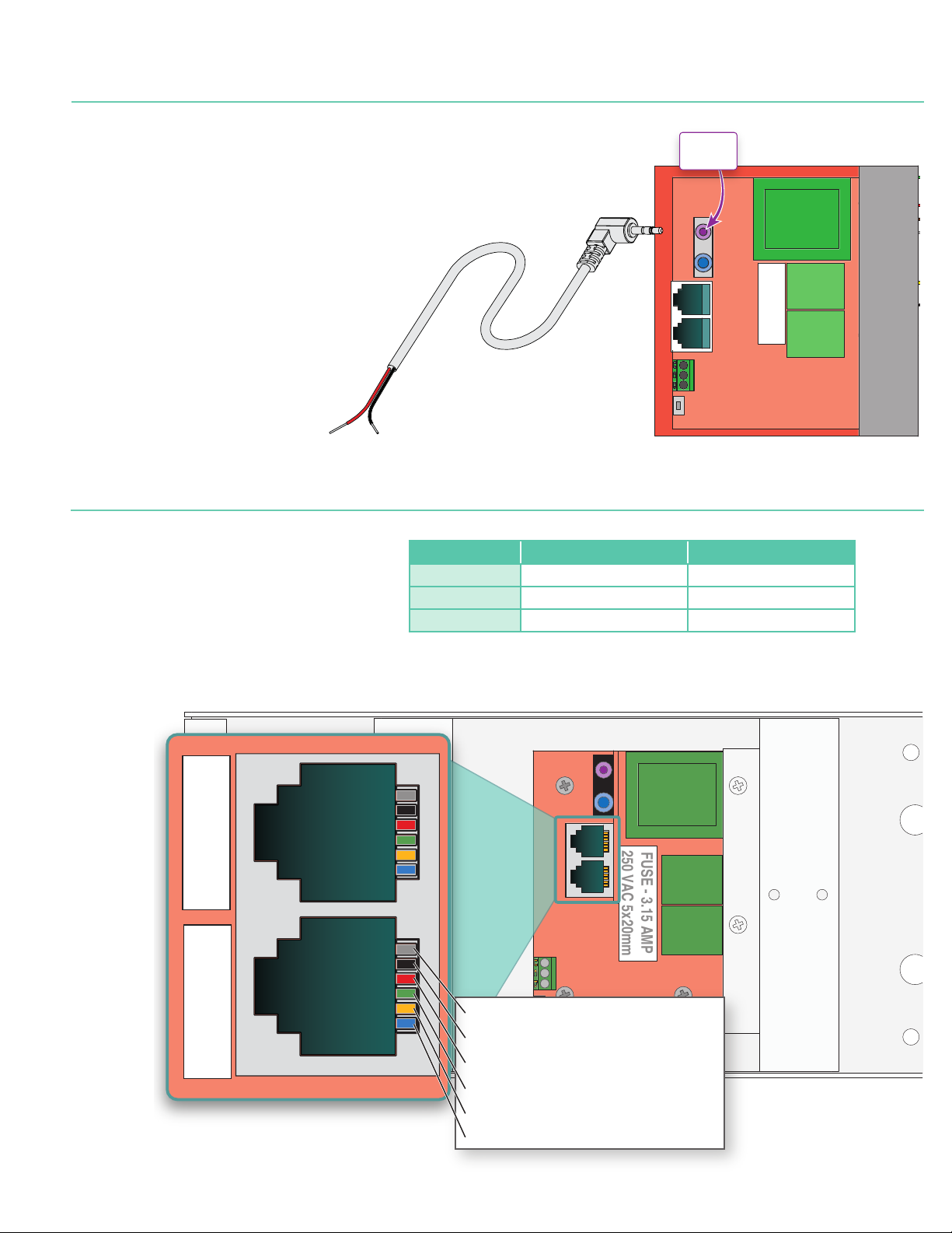
The LVC-IV comes with built-in connection for sending a DC trigger (4-2 8 VDC) from the projector to the projection screen.
1.
Connect remote trigger voltage from projector to the low-voltage trigger cable.
2.
Plug the mini-jack plug of the low-voltage trigger cable to the LVC-IV (Figure 4).
3.
When projector is 'ON' the low-voltage output of the projector will cause LVC-IV to
deploy projection screen. When projector 'OFF' the low-voltage is removed from
LVC-IV and projection screen will retract into case.
Section 5 - RS232 / RS485 Information
Figure 4
Low Voltage
Trigger
4-28 VDC
250 VAC 5x20mm
FUSE - 3.15 AMP
RS232 / RS485 CommPort Parameters:
1. Frequency (BAUD Rate): 2400
2. Data long code : 8
3. Parity Check : N
4. Start bit : 1
5. Stop bit : 1
6. Flow Control : NONE
6 5 4 3 2 1
PINS
6 5 4 3 2 1
PINS
COMMAND COMMAND STRINGS
UP 9A 01 01 00 0A DD D7
STOP 9A 01 01 00 0A CC C6
DOWN 9A 01 01 00 0A EE E4
For more detailed programming instructions or group control go to:
http://www.draperinc.com/DraperPro
(registration required)
REMARK
ID No. : 1 / Channel : 01
ID No. : 1 / Channel : 01
ID No. : 1 / Channel : 01
PIN 6 - RS485-B or RS232-Rx
PIN 5 - RS485-A or RS232-GND
PIN 4 - Ground
PIN 3 - Up
PIN 2 - Down
PIN 1 - 5VDC Output
Page 4
220-240V LVC-IV Low-Voltage Control Module
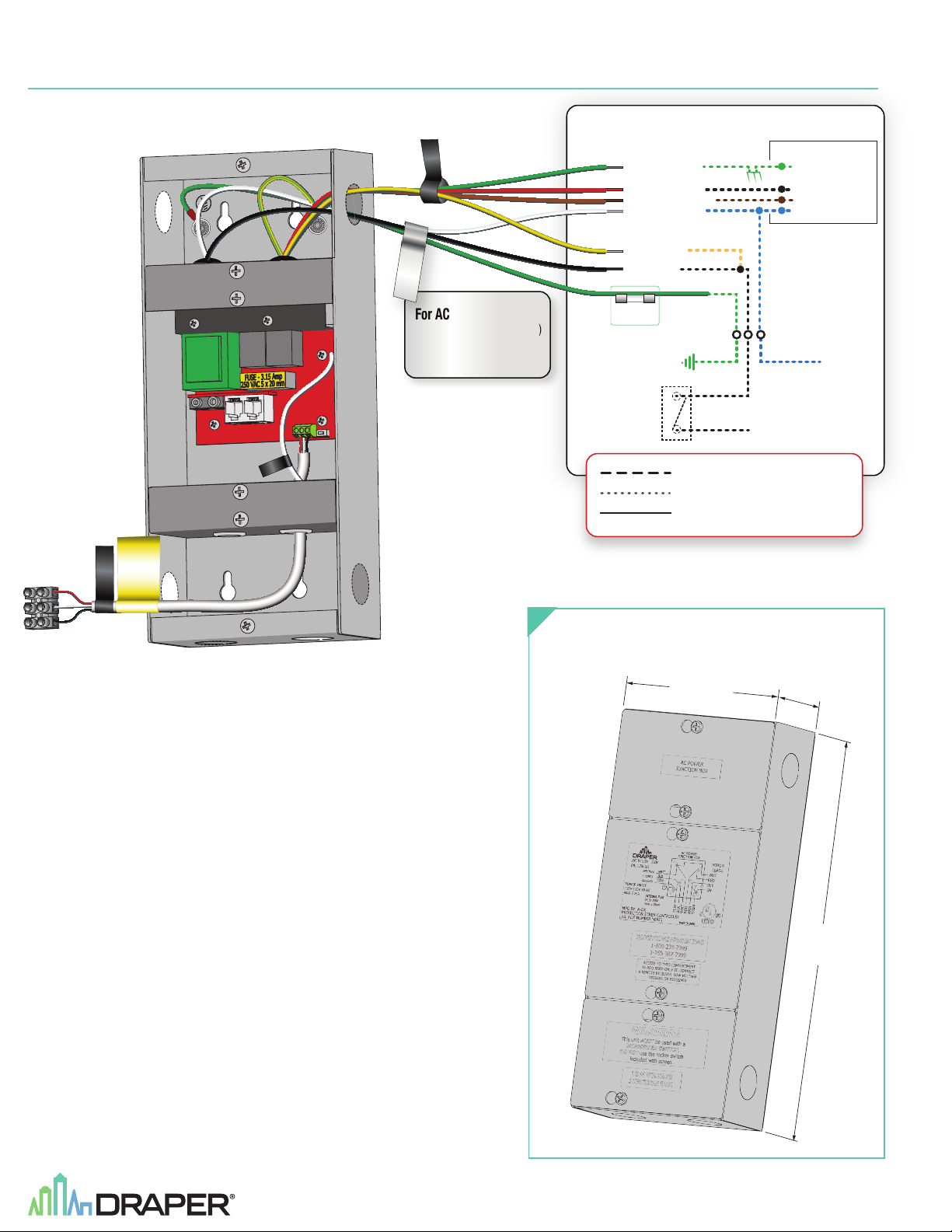
Section 6 - Wiring LVC-IV to Motor
page 4 of 4
MOTOR LEADS
AC POWER INPUT
For AC supply wires:
Wiring LVC-IV to Screen Motor
INTERNAL SCREEN WIRING
GREEN/YELLOW (Ground)
RED - to screen (directional)
BROWN - to screen (directional)
WHITE - Common to screen
& AC Neutral
YELLOW - to AC-Hot
(from LVC-IV MOTOR LEAD bundle)
BLACK - to AC-Hot
(from LVC-IV AC POWER bundle)
Extra Fuse
(3.15 Amp)
GREEN/YELLOW (Ground)
BLACK - (UP)
BROWN - (DOWN)
BLUE - (Common)
Attach appropriate ½" (13mm)
Trade Size connector to route
wiring through knockouts.
GND
ON/OFF
KEY SWITCH
N
to AC Power (L1)
RF Antenna
Wire
DRY CONTACT
CONTROLLER.
CLOSURE ONLY.
APPLYING VOLTAGE
HERE WILL DAMAGE
WARNING
WALL SWITCH
DASHED WIRING BY ELECTRICIAN
Low-Voltage Wiring by others
Factory Wiring
EXTERNAL LVC-IV
ENCLOSURE DIMENSIONS
114 mm
254
mm
56.2
mm
 Loading...