

Page 1

PENCIL
POWER DRILL
TAPE MEASURE
LEVEL
MALLET
HARDWARE
(by others)
LightBloc FlexShade
®
Overview - LightBloc FlexShade Components
INSTRUCTIONS
INSTALL ATI O N & OPERATION
TOOLS
REQUIRED
Clutch
Endcap
Endcap
Cover
Motor
Endcap
Motor
Gudgeon assembly
Retainer clip
Idler endcap
fastens to ceiling,
face or jamb
Endcap
Covers
Channel
Liner
Fabric
Retainer
Side channel - Includes ¾" x 1"
adjustable mounting angles
(Mounting angles provided for
"Inside" or "Jamb"mount installations.
For "Face Mount" applications,
Top/Back Cover
(STANDARD)
Fabric grommet
Stays
Shade
fabric
Slat bar
Sill channel see details
Roller
SILL CHANNEL
Inside Mount
3
1
/8" H x ¾" D
Channel
locator
Fabric guide
Face/bottom
cover
(STANDARD)
Side channel
Face Mount
2¾" H x ¾" D
CRANK ASSEMBLY
Crank
Handle
Crank Endcap
& Assembly
Read and understand all warnings (Page 2 of this document) before beginning installation.
Contents
Overview LightBloc FlexShade Components .................................................1
Please Read Warnings and Safety Information ..................................................2
Please Read Field Adjustments, Cleaning and Maintenance ............................2
Section 1 Preparation for Installation .............................................................3
Section 2 Side Channels ..................................................................................4
Section 3 Check Shade Fabric ........................................................................4
Section 4 Bead Chain Limits and Safety Device Installation
(for Units with Clutch or Spring Roller Operation) ...................... 5
CAUTION
Section 5 Check Shade Operation
(for Units with Clutch or Spring Roller Operation) ...................... 5
Section 6 Electrical Connections
(for Motorized Units) ....................................................................... 6
Section 7 Wiring Diagrams
(for Motorized Units) ....................................................................... 6
Section 8 Limit Switch Adjustments
(for Motorized Units) ....................................................................... 7
Section 9 Dimensions - LightBloc FlexShade ................................................8
If you have any difficulties installing or servicing your
LightBloc FlexShade, call your dealer or Draper, Inc.
Draper, Inc. | 411 S. Pearl St. Spiceland, IN 47385
draperinc.com | 765.987.7999 | 800.238.7999
© 2018 All Rights Reserved | FORM: LBFS_Inst_18
Page 2
LightBloc FlexShade
®
page 2 of 8
Important Safety Information Important Safety Information
Improper installation and use of the LightBloc FlexShade® can result in serious injury or death. Primarily, injuries can occur when the shade falls
due to imprecise installation, mishandling of the shade during installation or installation on an insufficient wall or ceiling structure. Please use
extreme care.
1.
Please read the following installation guidelines thoroughly and follow them
carefully. Failure to do so may cause product to fall or otherwise fail, and
could result in serious injur y.
2.
Installation and calibration of the shade should only be performed by an
authorized, qualified, and experienced professional.
3.
Do not affix the unit to wall or ceilings that have inadequate strength to
permanently hold the unit during use. It is the owner’s and installer’s responsibility
to confirm the wall or ceiling to which the unit attaches is sufficient to
permanently hold the weight and stress loads of the unit at all times. Draper, Inc.,
is not responsible for improper installation, application, testing or workmanship
related to the product at place of installation.
4.
It is the installer’s responsibility to make sure appropriate fasteners are used for
mounting.
5.
All brackets, fascia, head boxes, pockets, wall clips, and other hardware must be
installed level. shade must be level and square.
6.
Never leave the area while operating the shade during installation, maintenance,
or normal operation, unless it is secure and safe.
7.
Before testing or operation, carefully inspect the entire area and path of the shade
and areas underneath the shade to be sure no persons or objects are in the area.
WARNING
8.
During testing or operation, carefully watch the surrounding area for any potential
safety concerns including nearby persons or objects.
9.
After installation, the entire system should be carefully tested to ensure safe and
normal operation. Extreme care should be taken during testing to remain clear of
moving par ts to avoid possible injury.
10.
Operation of shade should be performed only by authorized and qualified
personnel, who have been trained in the safe and effective operation of the shade
& understand its safety features.
11.
The safety features of the shade should never be disabled, bypassed or
overridden. The system should not be operated until all safety features are
properly and completely installed, calibrated and tested.
12.
Shade may need to comply with local, state or district rules and regulations, in
particular when installed in schools. All applicable rules and regulations should
be reviewed before installation and use.
13.
Failure to precisely follow installation guidelines invalidates all warranties.
14.
Custom products/installations may not be reflected in this manual. Call Draper,
Inc., if you have questions regarding your installation.
Before Beginning Installation
1.
Look for any job site conditions that could inter fere with installation or operation
of the system.
2.
Read carefully and be sure to understand all installation instructions and all
related operations manuals. These instructions are intended to serve as a guide
for the installer and owner. They should be followed closely and combined with
the expertise of experienced qualified installers. Draper, Inc., is not responsible
for improper installation, application, testing or workmanship related to the
product at place of installation. Please retain all instructions for future use.
3.
Open cartons lengthwise.
4.
Locate and lay out all pieces.
5.
Inspect all boxes to make sure you have received the proper shade and parts.
Controls may be shipped separately, or in same carton as shade.
6.
If you have any difficulties with installing, servicing or operating your shade, call
your dealer or Draper, Inc., 765-987-7999.
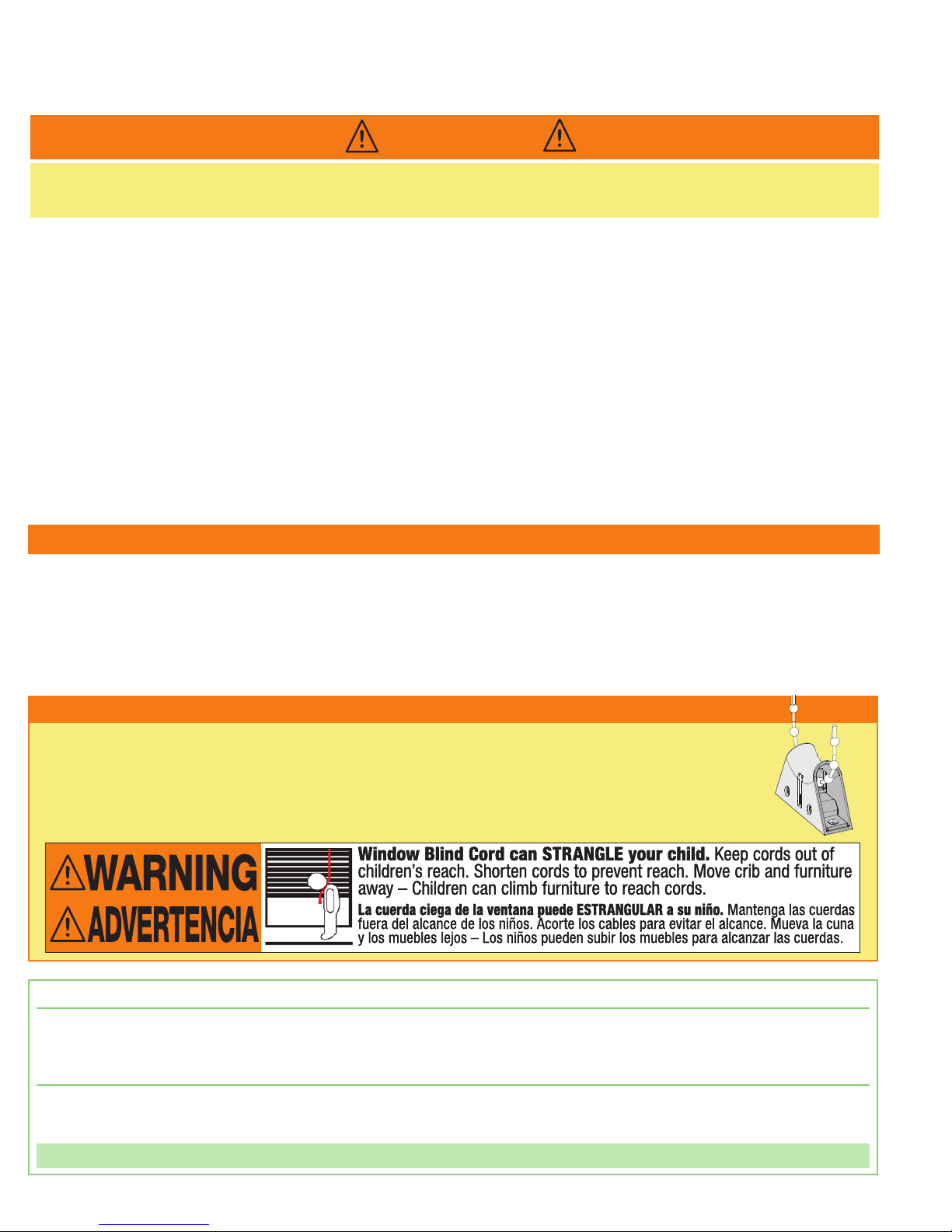
Child Safety Information
ANSI/WCMA A100.1-2018 standard (developed by the Window Coverings Manufacturer’s Association and the Consumer Product Safety
Commission) was established on December 15, 2018, to eliminate strangulation hazards for small children from hanging cords and chain loops.
When a Draper dealer specifies that custom shades comply with ANSI/WCMA A100.1-2018, Draper provides a pre-installed Spring-Loaded Chain
Tension Device (shown at right) for clutch-operated units. A warning label is attached to the kit and approved mechanical fasteners are included.
When properly installed, the tension device prevents the creation of a hazardous loop by maintaining tension on the bead chain. If not installed
properly, the shade is par tially inoperable. A warning label (shown below) is also added to the shade roller.
For more information, please see Draper's ANSI/WCMA A100.1-2018 compliance page: www.draperinc.com/windowshades/wcmacompliance.aspx
Field Adjustments
Each Draper Solar Control Shade is tested to ensure proper operation. Even with this testing, some field adjustments may be needed for telescoping.
If the shade is telescoping, place a piece of high quality gaffer tape about 1" wide on the exposed roller (where the fabric will cover it) on the side that the
fabric will be drawn toward. For example: if the fabric is tracking to the left, place the tape on the right side.
Cleaning and Maintenance
Window covering products manufactured by Draper, when properly installed, should require no operational maintenance or lubrication.
Most of Draper’s standard fabrics may be cleaned at the window by vacuuming with a soft brush attachment. They also may be cleaned by using a sponge
or soft cloth and mild solution of warm soapy water. A mild dishwashing liquid is recommended. A clean dry cloth is recommended for the metal finish.
Please Note:
Exceptions are Flocké and Phifer SW7000 fabrics, which must be cleaned with a dry art sponge.
Page 3

Endcap
20lb Clutch
Clutch
Endcap
2
3
Insert
Spear
Idler
Endcap
Top
End
Back
1
1
/2"
1
1
/2"
3
/
4"
3
/
4"
5
/
8
5
/
8
LightBloc FlexShade
Section 1 - Preparation for Installation
®
page 3 of 8
Caution: Before mounting shades, verify measurements on package label with shade.
Please Note: Installer is responsible for selecting mounting hardware appropriate for site conditions.
1.
FOR ALL: Open cartons lengthwise. Remove all pieces from carton. If shade has a detachable crank handle, remove universal
joint and shaft/bracket assembly by removing 2 screws from bottom of endcap (Fig. 1). Save universal joint & screws.
Figure 2
2.
FOR ALL: Remove face cover from
headbox by pulling down and out on
bottom edge of cover near endcaps. It
will snap off (Fig. 2). If this is a pocket
installation, remove screws at endcaps.
Bottom of cover box snaps down and
off at endcaps then slides out of slot in
cover box (Fig. 2).
Wall/Ceiling Pocket
3.
FOR ALL: Remove roller assembly
from headbox.
Please Note: If unit is motorized with a crank override, skip this step. Roller
assembly and headbox assembly must be installed as a unit — the roller
assembly cannot be removed without completely disassembling headbox.)
FOR CRANK OR MOTORIZED UNITS: Remove black plastic retainer clip from
idler end of roller and retainer clips from motor studs. Save these clips to replace
when re-assembling. Lift idler out of bracket Depress spring-loaded pin by pressing
roller toward pin end endcap until clutch hooks are free from operator endcap.
Figure 3:
Idler End Operator End
Motorized
Idler
Endcap
Idler End
of Roller
Remove roller assembly from headbox.
FOR BEAD CHAIN CLUTCH UNITS: Lift up on clutch end so that clutch hooks
can disengage from operator endcap. Depress spring-loaded pin by pressing roller
toward pin end endcap until clutch hooks are free from operator endcap. Remove
roller assembly from headbox.
Please Note: It may be necessary to locate and drill a hole for conduit connector
Retainer Clip
Be sure retainer clip is installed.
(Conduit connector is not supplied) (Fig. 4).
CRANK ASSEMBLY
Crank
Handle
Crank Endcap
& Assembly
Figure 1
FOR ALL: Verify dimensions of opening and refer to order for overall dimensions
of unit. Determine location of headbox directly above and centered on opening.
It is critical that headbox is installed absolutely level (use shims and caulking if
needed). Install headbox assembly using appropriate fasteners through pre-drilled
Idler
Idler End
of Roller
Crank
holes in endcaps, then drill through cover for wall/ceiling mounting (Fig. 5).
Figure 4
Figure 5
Retainer Clip
Be sure retainer clip is installed.
Bead Chain Clutch
Idler
Endcap
Wall/Ceiling (face) or Jamb Mount
Existing Pocket
Retainer Clip
Idler End
of Roller
Page 4

Face Mount Jamb Mount
Plug Button
1" x
3
/4" angles
toward window
(standard)
LightBloc FlexShade
Section 2 - Side Channels
®
page 4 of 8
Figure 6
Fabric Guide
Figure 7
Section 3 - Check Shade Fabric
Bottom edge
of mounting
angle must
be mounted
flush with
bottom edge
of side
channel
Caution: For motorized units, make sure POWER IS OFF before making any
1.
FOR ALL: Install side channels (NOTE: Ensure side channels, headbox, and sill
channel are square).
A.
Install channel locater and fabric retainer in top of each side channel. Lightly
tap channel locater with a rubber mallet to en- sure it is fully seated in side
channel. Slide into place (Fig. 6).
B.
For face mount, side channel mounts on surface of wall or window mullion.
Fasteners go through side channels. Plug buttons should be used to cover
holes (access and mounting holes will be pre-drilled) (Fig. 7).
C.
For inside or jamb mount, attach mounting angles to side channels. Install side
channel with mounting angle toward window, if depth will allow, so it is not
visible (it can also be installed toward room). Bottom edge of mounting angle
must be mounted flush with bottom edge of side channel. Fasteners will go
through mounting flange (Fig. 7).
2.
FOR ALL: Install sill channel between
side channels using appropriate
fasteners (Fig. 8). On some large
LightBlocs, sill channel is replaced by
an angle.
Please Note: Be sure of a centered and
snug fit between side channels.
3.
FOR ALL: Re-install roller assembly
by generally reversing procedures in
Section 1.
FOR SPRING ASSISTED CLUTCH OPERATOR: Spring has been pretensioned
in factor y. Notch on spring roller should be positioned down. Rotate roller so that
spear end can be worked out of slot in spear endcap. Remove roller assembly
from headbox.
4.
FOR MOTORIZED UNITS: Complete electrical wiring according to national and
local codes.
Please Note: Opaque caulking around perimeter of cover, side channels, and sill
may be necessary for complete light block—especially for jamb mounts where
window openings are not square.
electrical connections. Use extreme caution when working with
electric motors.
Figure 8
Inside Mount
3
1
/8" H x ¾" D
Face Mount
2¾" H x ¾" D
1.
With fabric and slat fully raised, pull slat bar forward, out of headbox and
in front of side channels.
2.
Activate operator (crank, spring roller, bead clutch, or electric) to
completely lower shade fabric. Repeat several times. With the shade
fabric hanging in front of side channels, check fabric hang. Shade fabric
should hang straight and equally spaced between outside edges of side
channels.
3.
If misalignment still occurs, correct by sticking a small (approximately 2")
piece of cloth tape directly to roller to affect direction the fabric runs. (For
example, fabric hanging too far left may be corrected by placing tape on
right end of roller beneath fabric. This, in effect, makes that end of the
roller larger, therefore taking up more fabric.)
Figure 9
Lip along bottom edge of headbox
Slat Bar
Side Channels
Channel Locator
Fabric Retainer
Light Seal
Fabric Guide
Fabric
Rivet
Stay Pocket
Steel Stay
Side Channel
¾" x 2 ¾"
Page 5
Slat Bar
Catch
Sill Channel
LightBloc FlexShade
®
Section 4 - Bead Chain Limits and Safety Device Installation
(for Units with Clutch or Spring Roller Operation)
page 5 of 8
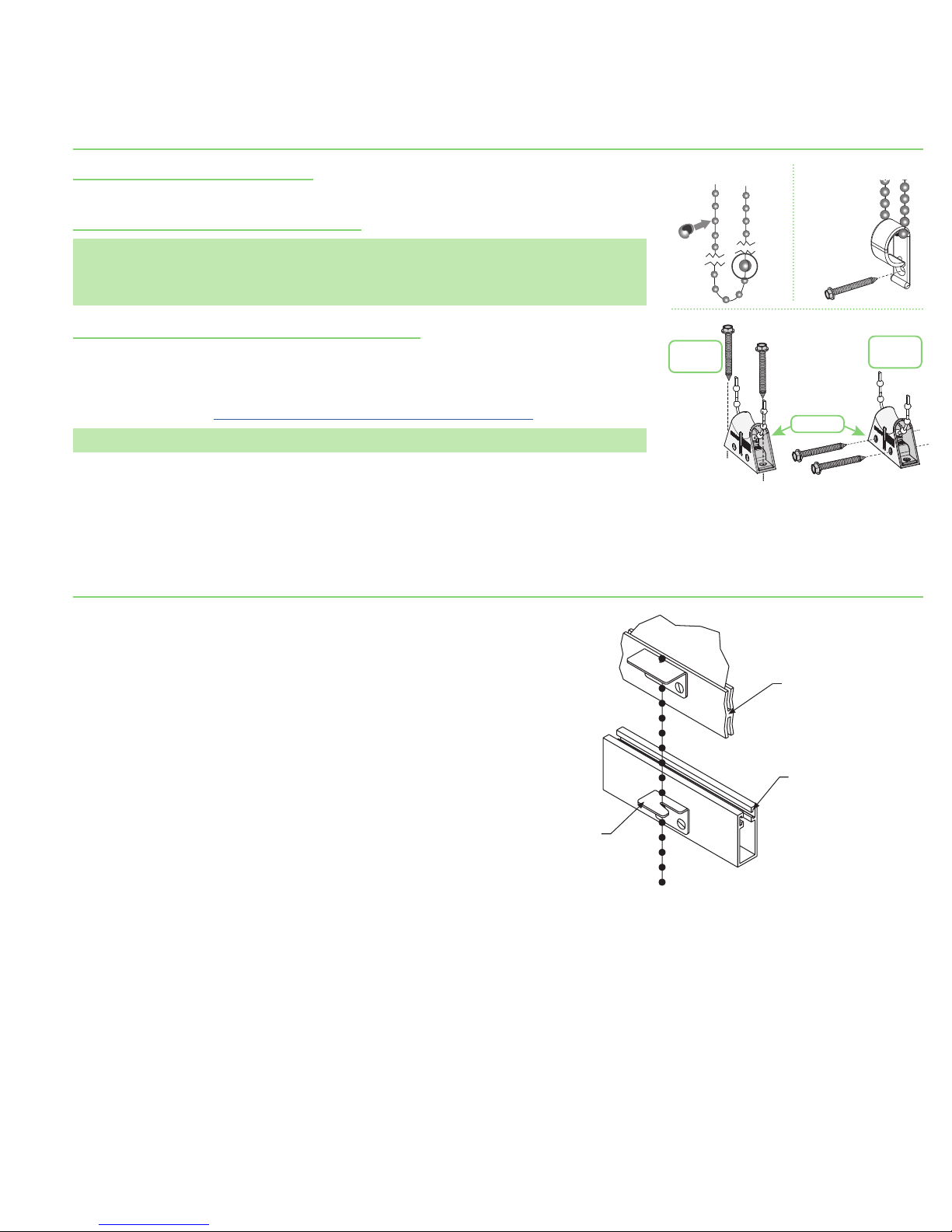
Section 4.1 - Attaching Stop Balls
1.
Set upper and lower travel limits by installing stop balls to bead chain (crimp closed using pliers) (Fig. 7).
Section 4.2 - P-Clip Cord Tension Device
Attach
Stop Balls
Please Note: Draper Bead Chain Clutch Operated shades that do not comply with WMCA/ANSI Standard
A100.1-2012 come with a cord tension device pre-attached to bead chain (Fig. 8). This device
must be attached to wall, jamb or sill so that bead chain is held taut enough that children
cannot pull it away from wall or fit their head into loop.
Section 4.3 - Spring-Loaded Cord Tension Device
Draper LightBloc FlexShade complies with WMCA/ANSI Standard A100.1-2018, a Spring-Loaded Cord
Tension Device comes installed on bead chain (Fig. 9). An approved permanent warning label and approved
Sill
Mount
mechanical fasteners (wood screws) are included. Device is designed so that children cannot pull bead chain
away from wall or fit their head into loop. (See safety note on page 2).
For more information, visit www.draperinc.com/WindowShades/WCMAcompliance.asp.
Please Note: Over-tightening screws will damage Spring Loaded Tension Device.
Section 5 - Check Shade Operation (for Units with Clutch or Spring Roller Operation)
Attach bead chain to slat bar and catch to sill channel. To operate shade, pull
down, locking in place using the bead chain (Fi g . 11).
Figure 10
Crimp
Closed
with
Pliers
Figure 8Figure 7
Figure 9
Tensioner
Jamb
Mount
Page 6

Controls & System Overview
Controls & System Overview
Controls & System Overview
Data Cable Pin-Out - RJ45 ConnectorMOTOR Pin-Out - RJ9 Connector
LightBloc FlexShade
®
page 6 of 8
Section 6 - Electrical Connections (for Motorized Units)
Caution: For motorized units, make sure POWER IS OFF before making any electrical connections. Use extreme caution when working with electric motors.
Shade operates on 110-120v, 60 Hz. current. Shade ships with internal wiring complete and control switch(es) fully boxed, and standardly supplied with a 6’ cable
lead. Longer lead can be substituted by removing two screws in motor end of roller, removing lead, plugging new lead in, and replacing screws. Wire to connect
shade to switch(es) and switch(es) to power supply should be furnished by installer. Connections should be made in accordance with attached wiring diagram,
and wiring should comply with national and local electrical codes. Only RTS and 485 motors can be wired in parallel.
Please Note: All operating switches should be “off” before power is connected.
Please Note: For low voltage wiring requirements, Draper recommends consulting with a professional low voltage electrical contractor. It is very important that
shielded and stranded CAT 5 cable be used to prevent any electrical interference.
Please Note: Wiring diagram for standard right-hand motor placement with fabric from rear of roller, or left-hand motor placement with fabric from front of roller.
For left hand motor placement with fabric from rear of roller or right hand motor placement with fabric from front of roller, Red is “Up” and Black is
“Down.”
Please Note: All Motorized LightBloc FlexShade motors are equipped with M12 Connectors.
Section 7 - Wiring Diagrams (for Motorized Units)
Sonesse 120VAC Motors
120V
MOTOR
M12
Connector
W B R G
B
110-120V Line
NOTE: Test shade operation
If shade direction does not
correspond with the switch
orientation, turn power back
off and switch the red and black
wires from the motor to the switch.
Do not wire motors in parallel without
written permission from Draper.
Dashed Wiring
by Electrician
Control
Switch
Single Gang
Box (by others)
Sonesse RTS 120VAC Motors
RTS
MOTOR
120V
M12 Connector
Telis 1
RF Remote
B W G
STOP
Decora RTS
110-120V Line
Wireless Keypad
Dashed Wiring
by Electrician
Sonesse RS485 120VAC Motors
Bus Power
Supply
110V
LAN
BUS IN
110-120V Line
RS485
120VAC
Motor
B W G
DATA
CABLES
M12
Connectors
Outlet
Data Hub
RS485
120VAC
Motor
B W G
110-120V Line
BUS OUT
to next
DATA HUB
STOP
Wall Switch
Data Cable
with RJ45
Connector
Dashed Wiring
by Electrician
4 - GROUND - (BROWN)
3 - POWER + (BLUE)
2 - DATA - (ORANGE)
1 - DATA + (ORANGE/WHITE)
1 - DATA + (ORANGE/WHITE)
2 - DATA - (ORANGE)
3 - N/A (GREEN/WHITE)
4 - POWER + (BLUE)
5 - POWER - (BLUE/WHITE)
6 - N/A (GREEN)
7 - GROUND - (BROWN/WHITE)
8 - GROUND - (BROWN)
Page 7

Bottom View
ROOM SIDE
+
+
Bottom View
Programming
Button
Pen
BACK
BACK
LightBloc FlexShade
®
Section 8 - Limit Switch Adjustments (for Motorized Units)
Section 8.1 - Standard and Quiet Motors (All procedures shown are for Standard Roll. Inver t orientation for Reverse Roll)
Section 8.1.1- Push Button Limits
1.
Fully depress both limit switch push buttons, then
operate wall switch to ensure system works properly.
2.
Raise shade to desired “up” stop position.
3.
Set upper limit by depressing proper (back) push button.
4.
Lower shade to desired “down” stop position.
5.
Set lower limit by depressing proper (front) push button.
Section 8.1.2 - Screw-Type Limits
1.
Determine which direction of fabric travel corresponds
with arrows on motor.
2.
Operate shade to desired “down” stop position.
Set limit by turning proper socket toward “+”
Caution:
- All switches must be in “off”
position before adjusting limit
switches.
- Be prepared to shut off
manually while testing.
- Shade may be damaged by
running shade fabric down
too far to expose roller.
- If using a group control system,
each limit switch must be set
prior to connecting to system.
- Motor must be installed so limit
switches are pointed down.
to lower limit, and “-” to raise it.
3.
Operate shade to desired “up” stopping position. Set limit by turning proper screw
toward “-” to raise limit, and “+” to lower it.
Section 8.2 - Limit Adjustments (RS485 Motors)
For limit setting instructions on these motors, see instructions packaged
with RS485 Address/Limit Setting Tool (part# C156.241).
PUSH BUTTON LIMITS
ROOM SIDE
Front
Back
GLASS SIDE
Bottom View
SCREW-TYPE LIMITS
Front
Back
GLASS SIDE
+
+
Bottom View
Standard right-hand
motor configuration shown
Side View
Standard right-hand
motor configuration shown
Screws
Side View
page 7 of 8
Section 8.3 - Limit Switch Adjustments—RTS Motors
Section 8.3.1 - Programming Instructions
1.
Connect power to one motor. Select a transmitter channel to assign motor. Hold UP & DOWN buttons until motor jogs, then release.
2.
Check motor direction. To reverse motor direction, hold MY/STOP button for 5 seconds until motor jogs. Check direction again.
Please Note: Failure to complete Step 2 before Step 3 can only be corrected with a motor reset (Section 8.3.6).
3.
Move motor to upper limit position. Hold MY/STOP & DOWN buttons until motor moves down, then release.
Stop shade at desired lower limit position using MY/STOP button (shade will not stop on its own).
UP and DOWN buttons can be used to adjust the lower limit position if needed.
4.
While motor is at lower limit, hold UP & MY/STOP buttons until motor moves up, then release.
The shade should move to upper limit and stop.
5.
Next, hold MY/STOP button for five seconds until motor jogs.
6.
Put motor into USER MODE by pressing small programming button (Fig. 13) on back of transmitter until motor jogs.
7.
Disconnect power to this motor and move to next motor in installation and start with step 1.
8.
Reconnect motor to power when all motors are programmed.
Section 8.3.2 - Setting an Intermediate Stop - Shade MUST BE in USER mode.
1.
Move shade to desired mid-point location and hold MY/STOP button until motor jogs.
2.
To test, press MY/STOP button when motor is standing still. Shade will move to that intermediate location.
3.
To delete an intermediate stop, go to intermediate stop and hold MY/STOP button until motor jogs.
Section 8.3.3 - Add a Channel - Shade MUST BE in USER mode.
1.
Select channel currently operating motor, then hold programming button until motor jogs.
2.
Select new channel to add to motor, then hold programming button until motor jogs.
3.
The motor should now work on both old and new channel.
Section 8.3.4 - Delete a Channel - Shade MUST BE in USER mode.
1.
Select channel operating motor that you want to keep, then hold programming button until motor jogs.
2
Select channel to remove, then hold programming button until motor jogs.
Motor should now only work on channel kept from Step 1.
Section 8.3.5 - Adjust Limits in User Mode
1.
Move motor to limit (upper or lower) to be changed. Shade must move to previously set limit and will stop automatically.
2.
Hold UP & DOWN buttons until motor jogs.
3.
Move motor to its new limit location and hold MY/STOP button until motor jogs.
Section 8.3.6 - Reset Motor
1.
Disconnect power for 5 seconds and reconnect to power for 15 seconds. Disconnect power for 5 seconds, then reconnect to power and leave connected.
Shade should roll down a few inches and stop.
2.
Hold programming button (Fig. 13) for 15 seconds. Motor will jog up and down once; pause and then jog a 2nd time.
Motor is now reset and ready to be programmed.
Figure 12
UP
STOP
DOWN
LED Lights
Channel
Selector
Figure 13
Pen
Programming
Button
Page 8

)
Top/Back Cover
(3
LightBloc FlexShade
®
Section 9 - Dimensions - LightBloc FlexShade
⁷₈
" (22.23mm)
Unit width = Cloth width + 2
Endcap Assembly
Stay
₈
" (60.33mm)
Face/Bottom Cover
⁷₈
" (22.23mm)
2"
⁵₁₆
"(100.01mm)
3
(50.8mm)
page 8 of 8
3
⁷₁₆
(87.32mm)
Light
Seal
Overall shade height
Cloth
"
₄
"
1
(44.45mm)
2
₄
(69.85mm
"
1
⁹₁₆
9.69mm)
1
₁₆
(30.16mm)
Slat
Bar
Weight
Bar
Liner
Side Channel
Sill
Channel
₄
"
"
Clear opening = Cloth width - 3
Cloth width
Side channel width = Cloth width + 2
₈
" (79.38mm)
₈
" (60.33mm)
1
⁹₁₆
" (39.69mm)
1
₁₆
" (30.16mm)
2
₄
" (69.85mm)
"
 Loading...