

Page 1
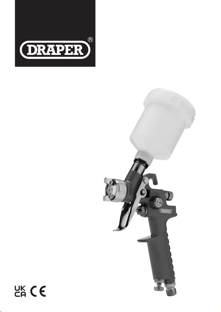
7 PIECE
HVLP AIR
PA I NT S P R AY
GUN KIT
28374
EN
Original Instructions
Version 1
Page 2
1. Preface
These are the original product instructions. This
document is part of the product; retain it for the life
of the product, passing it on to subsequent holders.
Read this manual in full before attempting to
assemble, operate, or maintain this product.
This Draper Tools manual describes the purpose
of the product and contains all the necessary
information to ensure its correct and safe use.
Following all the instructions and guidance in
this manual will ensure the safety of both the
product and the operator and increase the
lifespan of the product.
1.1 Product Reference
User Manual for: 7 Piece HVLP Air Paint Spray Gun Kit
Stock No: 28374
Part No: DAT-HASGK7
1.2 Revisions
Version 1: June 2022
First release
As our manuals are continually updated, always ensure
that the latest version is used.
Download the latest version from:
drapertools.com/manuals
All photographs and drawings within this manual are
supplied by Draper Tools to help illustrate correct
operation of the product.
Every eort has been made to ensure the
information contained in this manual is accurate.
However, Draper Tools reserves the right to amend
this document without prior warning. Always use the
latest version of the product manual.
1.3 Understanding the Safety Content
WARNING! – Situations or actions that may result
in personal injury or death.
CAUTION! – Situations or actions that may result
in damage to the product or surroundings.
Important – Information or instructions of particular
importance.
1.4 Copyright © Notice
Copyright © Draper Tools Limited.
Permission is granted to reproduce this manual for
personal and educational use ONLY. Commercial
copying, redistribution, hiring, or lending is strictly
prohibited.
No part of this manual may be stored in a retrieval system
or transmitted in any other form or means without written
permission from Draper Tools Limited.
In all cases, this copyright notice must remain intact.
– 2 –
Page 3
2. Contents
EN
1. Preface 2
1.1 Product Reference 2
1.2 Revisions 2
1.3 Understanding the Safety Content 2
1.4 Copyright © Notice 2
2. Contents 3
3. Warranty 4
4. Product Introduction 5
4.1 Scope 5
4.2 Specication 5
5. Health and Safety Information 6
5.1 General Health and Safety Precautions 6
5.2 Additional Safety Instructions for Air Tools 6
6. Identication and Unpacking 8
6.1 Product Overview 8
6.2 What’s in the Box? 9
6.3 Packaging 9
7. Preparation Instructions 10
7.1 Preparing the Air Supply for Use 10
Cleaning the Product and Accessories
7.2
Before First Use
11
9.4 Troubleshooting 18
10. Returns and Disposal 20
11. Explanation of Symbols 21
Assembly, Filling and Connection to the
7.3
Air Supply
8. Operating Instructions 13
8.1 The Regulator 13
8.2 The Air Control Dial 13
8.3 The Fluid Control Dial 14
8.4 The Spray Control Dial 14
8.5 The Air Cap 14
8.6 The Trigger 15
8.7 Notes on Use 15
9. Maintenance and Troubleshooting 16
9.1 General Maintenance 16
9.2 Cleaning the Spray Gun 16
9.3 Storing the Product 17
11
– 3 –
Page 4

3. Warranty
Draper Tools products are carefully tested and inspected
before shipment and are guaranteed to be free from
defective materials and workmanship.
Should the tool develop a fault, return the complete tool
to your nearest distributor or contact Draper Tools
directly. Contact information can be found at the back of
this manual.
Proof of purchase must be provided.
If, upon inspection, it is found that the fault occurring is
due to defective materials or workmanship, repairs will
be carried out free of charge.
parts and labour for six months from the date of purchase.
Where tools have been hired out, the warranty period
covers 90 days from the date of purchase.
This warranty does not apply to any consumable parts,
batteries or normal wear and tear, nor does it cover any
damage caused by misuse, careless or unsafe handling,
alterations, accidents, or repairs attempted or made by
any personnel other than the authorised Draper Tools
repair agent.
In all cases, to make a claim for faulty workmanship or
materials within the standard warranty period, please
contact or return the product to the place of purchase.
Proof of purchase may be required.
This warranty period covers
If the place of purchase is no longer trading or if you
experience any diculties with your warranty, please
contact Customer Services with the product details and
your proof of purchase. Contact details can be found at
the back of this manual.
If the tool is not covered by the terms of this warranty,
repairs and carriage charges will be quoted and charged
accordingly.
This warranty supersedes any other guarantees
expressed or implied and variations of its terms are not
authorised.
Your Draper Tools guarantee is not eective until you can
produce, upon request, a dated receipt or invoice to
verify your purchase within the guarantee period.
Please note that this warranty is an additional benet
and does not aect your statutory rights.
Draper Tools Limited
– 4 –
Page 5
4. Product Introduction
EN
4.1 Scope
This product includes two gravity-fed high velocity, low
pressure (HVLP) spray paint guns for use with
compressed air systems. HVLP spray guns deliver more
uid at lower pressures and are designed to provide a
ner nish than other types of spray gun. The larger
1.4mm spray gun is suitable for use with medium
viscosity uids and delivers a moderate ow. Use the
smaller 0.8mm spray gun for ner operations with lower
viscosity liquids.
4.2 Specication
Stock No. 28374
Part No. DAT-HASGK7
HVLP spray gun 1.4mm:
Nozzle 1.4mm
Cup capacity 600ml
Max. operating air pressure 3.5bar/50psi
Air inlet 1/4" BSP
Net weight 0.4kg
Part of our core range, this product is suitable for regular
use by enthusiasts and tradespersons alike.
WARNING! This product is not a toy and must be
respected.
Read this manual in full before attempting to assemble,
operate or maintain the product, and retain it for later use.
HVLP spray gun 0.8mm:
Nozzle 0.8mm
Cup capacity 125ml
Max. operating air pressure 2.0bar/29psi
Air inlet 1/4" BSP
Net weight 0.2kg
Air regulator:
Max. inlet pressure 140psi
Gauge diameter 33mm
Scale colour (bar) Black
Scale colour (psi) Green
Net weight 0.1kg
Kit net weight 2.24kg
– 5 –
Page 6
5. Health and Safety Information
EN
Important: Read all Health and Safety instructions
before attempting to operate, maintain or repair this
product. Non-compliance with these instructions may
result in injury or damage to the user or the product.
5.1 General Health and Safety
Precautions
• Only authorised personnel who have carefully read
and understood this manual may operate, adjust and
repair this product.
• Observe all standard safety precautions and good
practices when working with air tools.
• Always wear adequate eye protection and a face mask
when using this product.
− Some products suitable for use with this product
may contain chemicals or toxic components.
− Avoid inhalation or contact with materials used
with this product.
− If contact occurs, seek medical advice as soon as
possible.
• Wear ear defenders and protective gloves while using
and cleaning this product.
• Keep your work environment clear and well-lit, with
bystanders at a safe distance.
• Use this product ONLY in well-ventilated areas to
avoid the build-up of fumes and allow paint particles
to disperse.
• Keep out of reach of children.
• Before every use, inspect the tools for missing,
broken, loose or corroded parts.
Important: DO NOT use this product if it is damaged
in any way. Contact Draper Tools to discuss repair and
replacement options.
• Ensure that all accessories and attachments are
securely tightened before use.
• Use the product only in the manner instructed in this
manual.
• DO NOT modify this product in any way.
• ONLY use spare parts supplied by Draper Tools.
• Stay alert at all times; DO NOT use this product while
tired or under the inuence of alcohol, drugs or other
medication.
5.2 Additional Safety Instructions for Air
Tools
• Compressed air can cause severe injury.
− ALWAYS turn o and disconnect the air supply
before making any adjustments to the product or
leaving it unattended.
− NEVER direct this product towards yourself or
others.
− Ensure that compressed air is not blocked by or in
contact with any part of your body.
• ONLY use clean, dry and regulated compressed air.
WARNING! NEVER use oxygen, combustible
gases or other bottled gasses as a supply for
this product. Use of these substances may
cause the product to explode.
• Use of a whip hose between the tool and the air supply
is recommended to reduce vibration.
CAUTION! Whipping hoses can cause severe
injury. Always check for and replace
• Ensure that the product is compatible with the air
supply before use.
• Ensure all connections are securely tightened.
• DO NOT exceed the maximum stated air pressure.
− The pressure of the connected air supply MUST
NOT exceed more than 10% of the rated pressure
of the product.
• DO NOT obstruct the ability of the trigger to release
once depressed.
• NEVER carry the tool by the hose.
• Some parts of the spray gun may become hot during
use.
− Allow the nozzle and paint cup to cool after use
before handling or adjusting them.
• NEVER spray ammable substances near open ames
or sources of heat and ignition.
− DO NOT smoke in the vicinity of this product.
• DO NOT use this tool in temperatures that do not fall
within 0–40°C.
– 6 –
Page 7

5. Health and Safety Information
EN
WARNING! The use of solvents that contain
halogenated hydrocarbons in pressurised
systems with aluminium or galvanised parts may
cause chemical reactions that result in an
explosion. This product contains components
halogenated hydrocarbons.
DO NOT use halogenated hydrocarbons with
this product. Many halogenated hydrocarbons
– 7 –
Page 8
6. Identication and Unpacking
EN
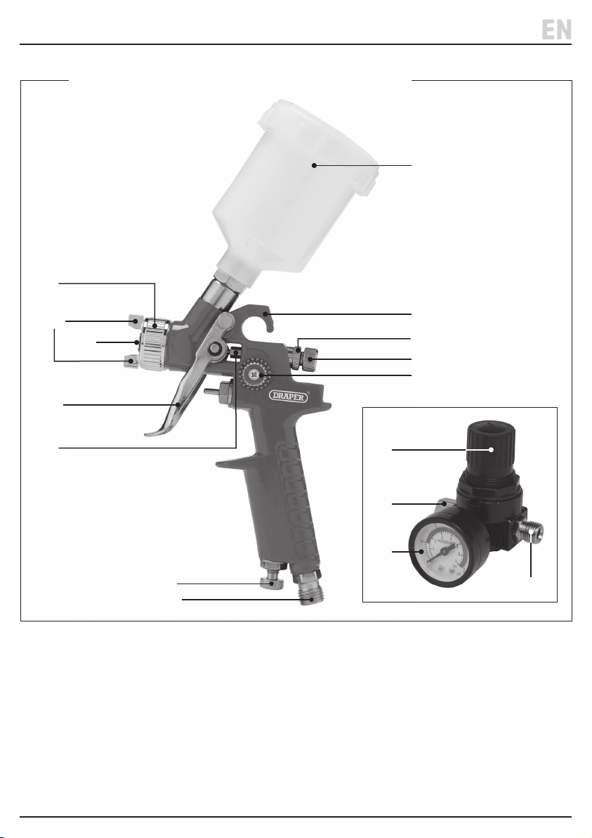
6.1 Product Overview
(1)
(8)
(10)
(7)
(12)
(5)
(1) Air cap
(2) Air control dial
(3) Fluid control dial
(4) Fluid control lock nut
(5) Fluid needle
(6) Hanging hook
(7) Nozzle
(8) Paint cup
(9) Spray control dial
(2)
(11)
(6)
(4)
(3)
(9)
(13)
(15)
(16)
(14)
(10) Spray direction control
(11) Spray gun air line inlet
(12) Trigger
(13) Regulator adjustment dial
(14) Regulator inlet
(15) Regulator outlet
(16) Regulator pressure gauge
– 8 –
Page 9
6. Identication and Unpacking
EN
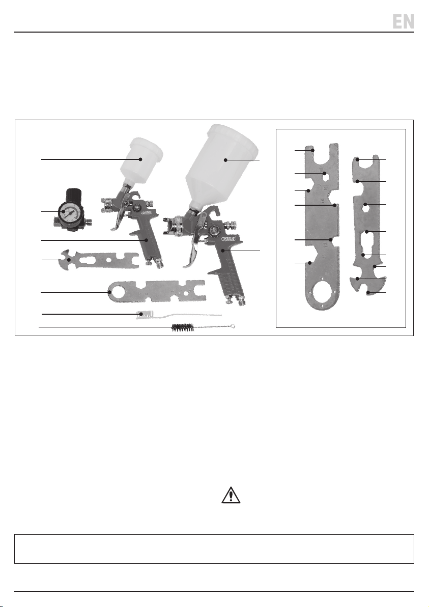
6.2 What’s in the Box?
Carefully remove the product from the packaging and
examine it for any signs of damage that may have
occurred during shipment.
Before assembling the product, lay the contents out and
check them against the parts shown below. If any part is
damaged or missing, do not attempt to use the product.
Please contact the Draper Helpline; contact details can
be found at the back of this manual.
(E)
(C)
(B)
(G)
(F)
(H)
(I)
(A) 1 x 1.4mm spray gun
(B) 1 x 0.8mm spray gun
(C) 1 x Regulator and gauge
(D) 1 x 600ml paint cup
(E) 1 x 125ml paint cup
(F) 1 x Large spanner tool
(F1) M12 spanner
(F2 ) M5 ring spanner
(F3) 12mm spanner
(F4) 14mm spanner
(F5) M6 spanner
(F6) M10 spanner
(F1)
(D)
(F2)
(F3)
(F4)
(F5)
(A)
(F6)
(G) 1 x Small spanner tool
(G1) 16mm spanner
(G2) 14mm spanner
(G3 ) M5 ring spanner
(G4) 14mm spanner
(H) 1 x Parts brush
(I) 1 x Pick-up tube brush
(G1)
(G2)
(G3)
(G4)
(G5)
(G6)
(G7)
(G8)
(G5) M6 spanner
(G6) M8 spanner
(G7) 12mm spanner
(G8) 9mm spanner
6.3 Packaging
Keep the product packaging for the duration of the
warranty period for reference should the product need to
be returned for repair.
Please visit drapertools.com for our full range of accessories and consumables.
– 9 –
WARNING! Keep packaging materials out
of reach of children. Dispose of packaging
correctly and responsibly and in accordance
with local regulations.
Page 10
EN
7. Preparation Instructions
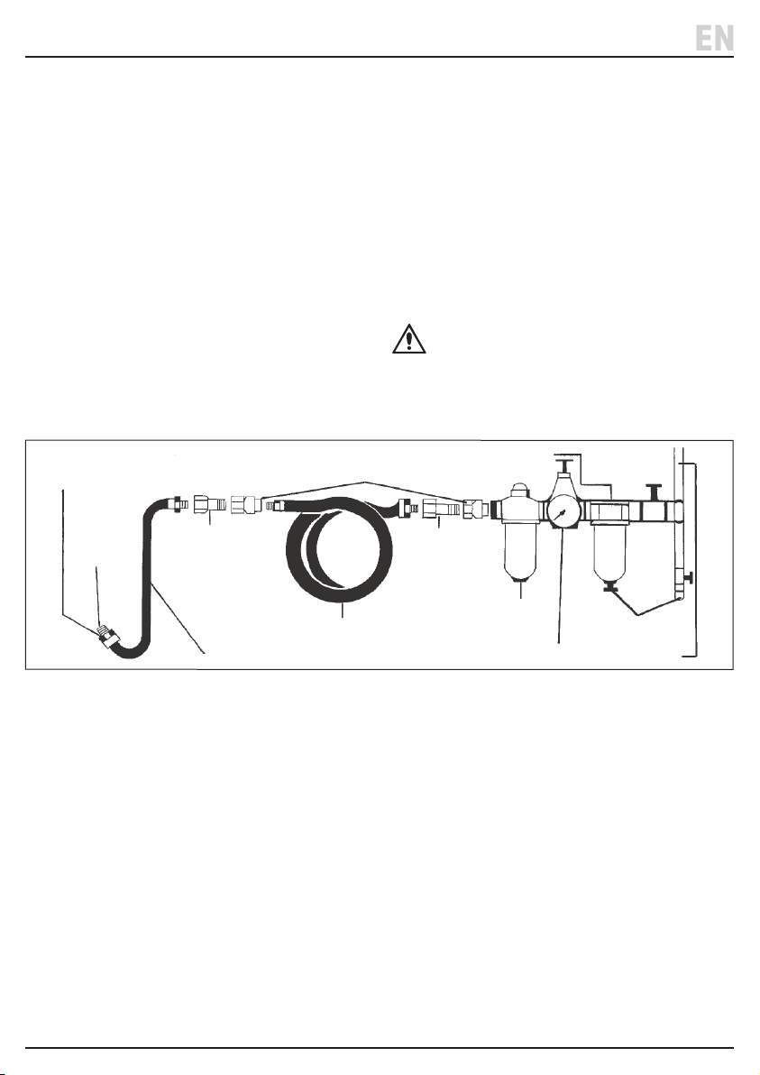
Do not install quick
coupling here
To your
air tool
Nipple
Nipple
Oiler
Whip hose Regulator* Air supply
Drain dailyAir line hose
Quick coupler
Water separation
Important: Before using this product, read and
understand all the safety instructions listed in this
manual.
7.1 Preparing the Air Supply for Use
The maximum operating pressure of these air tools is:
• 1.4mm spray gun: 3.5bar (50psi)
• 0.8mm spray gun: 2.0bar (29psi)
The compressed air system must be controlled by a
combination pressure regulator* and moisture lter; this
will ensure a constant supply of dry air at all times,
provided it is properly maintained.
*This product includes an on-gun regulator that may be
installed directly onto the tool’s air line inlet.
Important: Always check the machine operating
pressure before use.
Water in the compressor tank may cause considerable
corrosion to air tools; the compressor should be drained
daily to avoid excessive water in the air supply. Dirty or
wet air can signicantly shorten the lifespan of the
product.
When using an air tool with a hose over 25ft long,
increasing the bore of the hose to the next largest
available size is recommended (i.e. increase 3/8" to 1/2").
This will ensure adequate pressure and volume of air to
power the tool.
CAUTION! DO NOT lubricate the air line when
using paint spray guns. Ensure that any oil
device has been removed and any residual oil
purged from the system before connecting the
spray gun.
Fig.
1
– 10 –
Page 11
7. Preparation Instructions
EN
7.2 Cleaning the Product and Accessories
Before First Use
Before rst use, the spray guns must be cleaned
thoroughly to remove any oil, grease, and the protective
lm applied before shipment.
1. Disassemble the spray gun and immerse all parts and
accessories in spray gun cleaning uid.
2. Soak the parts for a few minutes.
3. Allow the parts to dry and then wipe them clean with
a damp cloth.
4. Assemble the spray gun (see 7.3) and half-ll the
paint cup (8) with thinners.
Important: DO NOT connect the spray gun to the
regulator or air line at this time.
5. Squeeze the trigger (12) to ush the thinners through
the spray gun until the paint cup is empty.
6. Immerse and soak the assembled spray gun in the
cleaning uid for a few more minutes.
7. Allow the parts to dry and wipe them clean.
7.3 Assembly, Filling and Connection to
the Air Supply
Important: It is recommended to use a 1/4" BSP thread
whip hose (Stock No. 54438) to connect the spray gun to
an air line in order to reduce vibration.
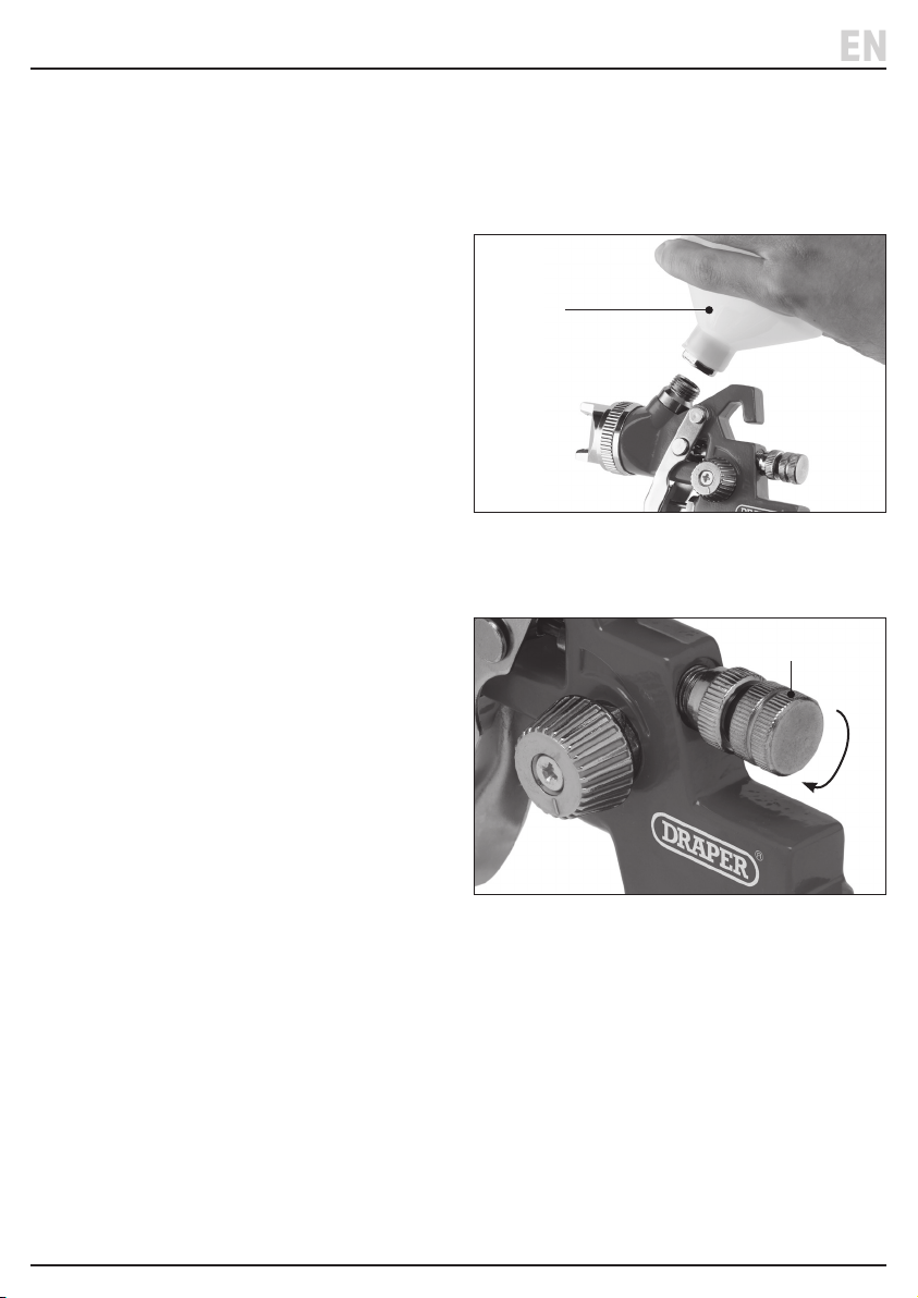
(D/E)
2 Fig.
1. Attach the appropriate paint cup (D) / (E) to the
uppermost thread on the spray gun body (Fig. 2).
(3)
3 Fig.
2. Rotate the uid control dial (3) clockwise as far as
possible to close the uid valve (Fig. 3).
Important: Loosen the uid control lock nut (5) to
ensure that the uid control dial is turned as far as
possible.
– 11 –
Page 12
7. Preparation Instructions
EN
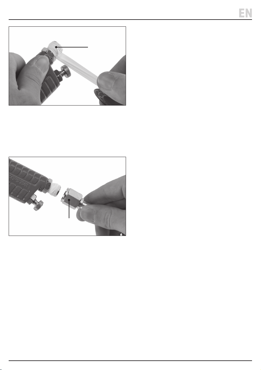
(11)
4 Fig.
3. Wrap a length of PTFE tape around the spray gun air
line inlet (11) (Fig. 4).
Important: For a more secure seal, the PTFE tape
should be wrapped in the opposite direction to the
thread.
5. Wrap a length of PTFE tape around the regulator inlet
(14) and attach it to the air line.
If using a whip hose, attach a parallel union nut
(Stock No. 25823) to the regulator inlet so the hose
can be connected.
6. Connect the air line to the regulator inlet.
If using a whip hose, wrap a length of PTFE tape
around the whip hose outlet and attach it to the
air line.
7. Unscrew the paint cup lid and pour in the required
quantity of paint.
Important: ALWAYS ensure that the paint is mixed
and thinned according to the manufacturer’s
recommendations.
8. Pressurise the air line when you are ready to begin.
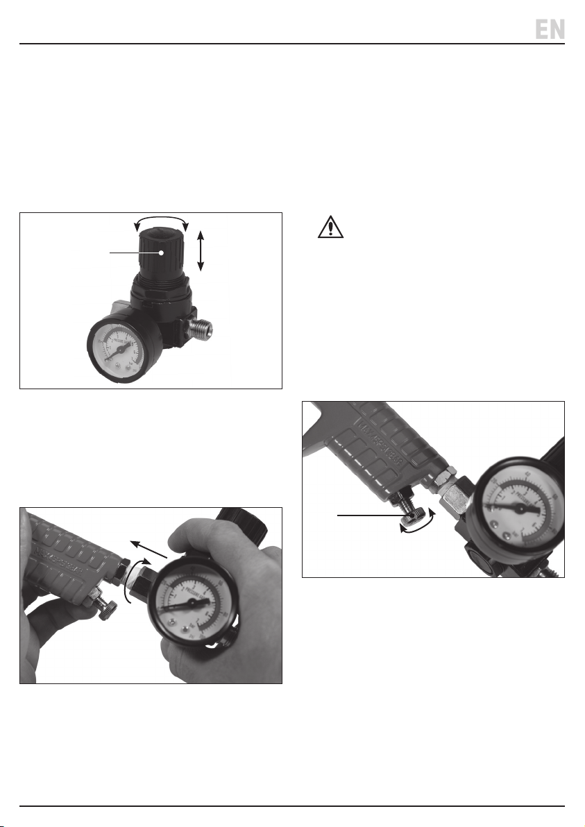
(15)
5 Fig.
4. Screw the spray gun air inlet into the regulator
outlet (15) (Fig. 5).
– 12 –
Page 13
8. Operation Instructions
EN
Important: Before using this product, read and
understand all the safety instructions listed in this
manual. DO NOT make any adjustments to the spray gun
while the trigger is depressed.
8.1 The Regulator
This product is supplied with a regulator and gauge,
which can be attached directly to the spray gun air line
inlet (11). Use the regulator to set and manage the
airow and pressure into the spray gun.
(13)
6 Fig.
• To adjust the air pressure to the spray gun, rotate the
regulator adjustment dial (13).
• To lock the regulator adjustment dial in place, press it
downwards; lift it upwards again to release it.
To use the regulator with the spray guns:
2. Before pressurising the system, rotate the regulator
adjustment dial (13) clockwise until resistance is met
to fully close the valve.
Important: If the adjustment dial is locked into place, it
can be released by lifting it away from the regulator unit.
3. Pressurise the air line.
4. Gradually rotate the adjustment dial anticlockwise to
increase the pressure the regulator pressure gauge
(16) indicates the desired value on the correct scale.
CAUTION! DO NOT exceed the maximum
rated pressure of the regulator or the attached
air tool.
5. Press the adjustment dial (13) downwards to lock it
and prevent unintentional changes.
Important: For more reliable results, ALWAYS adjust the
pressure upwards from a lower value. If the current
pressure must be reduced, adjust the pressure to a lower
value than required and carefully increase the pressure
until the desired value is reached.
8.2 The Air Control Dial
7 Fig.
1. Attach the regulator between the spray gun and air
line (see 7.3 Assembly, Filling and Connection to
the Air Supply) (Fig. 7).
(2)
8 Fig.
The air pressure can be ne-tuned by adjusting the air
control dial (2) on the spray gun. This is used to make
minor adjustments to the air ow after the required air
pressure has been set by the regulator (Fig. 8).
• Rotate the dial clockwise.
• Rotate the dial anticlockwise.
Important: The air control dial should typically remain in
the fully open position to allow the full ow of air into the
spray gun, but it may be used to make minor adjustments
for specic operations. The dial will click when it has
been wound to its fully open position.
– 13 –
Page 14
8. Operation Instructions
EN
8.3 The Fluid Control Dial
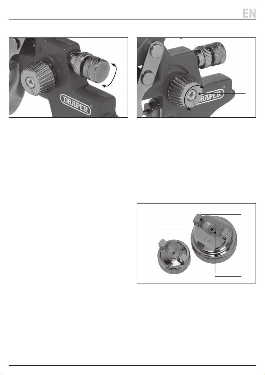
(3)
9 Fig.
The uid control dial (3) adjusts the amount of paint that
is released into the airow and the density of the spray
when the trigger is fully depressed (Fig. 9):
• To increase the paint quantity and density:
Rotate the nozzle regulator anticlockwise.
− The paint quantity should be increased when the
spray gun is positioned further from the surface or
when the paint mixture has a higher viscosity.
• To decrease the paint quantity and density:
Rotate the nozzle regulator clockwise.
− The paint quantity should be decreased when the
spray gun is positioned closer to the surface or
when the paint mixture has a lower viscosity.
Important: After adjusting, ensure that the uid control
lock nut (5) is tightened against the spray gun body.
8.4 The Spray Control Dial
(9)
10 Fig.
The spray control dial (9) adjusts the shape of the paint
jet released from the nozzle (Fig. 10):
• Rotate the dial clockwise.
• Narrower, rounder pattern: Rotate the dial
anticlockwise.
The spray control dial can be rotated more than 360°.
The line marker on the face of the dial indicates its
relative position.
8.5 The Air Cap
(19)
(17)
(18)
11 Fig.
The air cap (1) has three types of opening that aect the
pattern of the uid spray (Fig. 11):
• A hole for the nozzle head from which the uid is
dispersed (17).
• Atomising air holes (18) that break the uid into a ne
spray (1.4mm air cap only).
• Air horn holes (19) that shape the spray pattern as
required.
– 14 –
Page 15
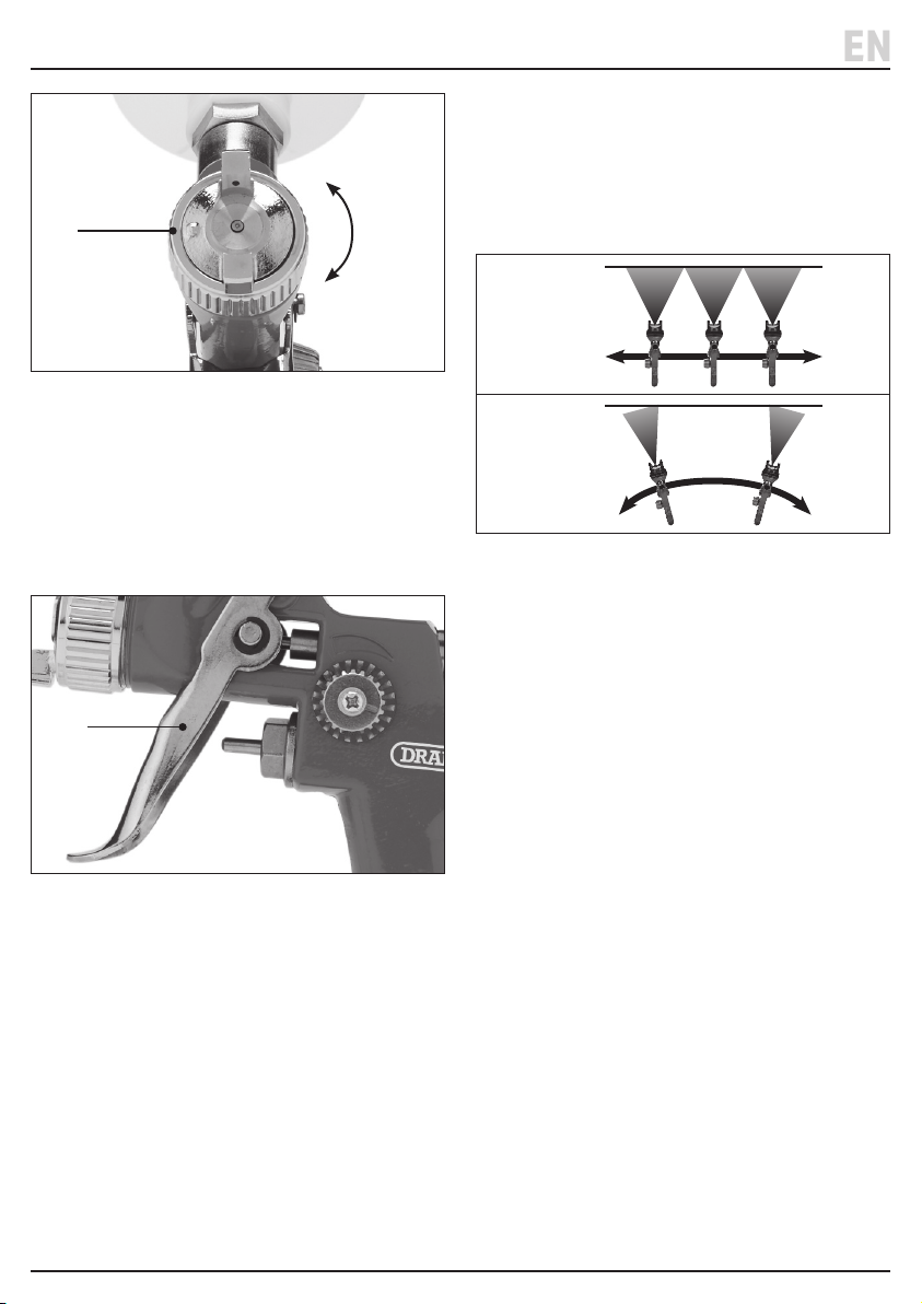
8. Operation Instructions
EN
(1)
12 Fig.
Once the spray pattern has been set using the control
dial, rotate the air cap (1) to change the orientation of
the jet (Fig. 12).
Important: ALWAYS ensure that the air cap remains
tightly secured after adjusting its orientation.
8.6 The Trigger
(12)
13 Fig.
Paint is released from the spray gun by squeezing the
trigger (12) (Fig. 13):
1. First, squeeze the trigger until resistance is met; this
opens the air valve.
2. Squeeze the trigger the rest of the way to draw the
uid pin back and release paint from the nozzle.
Important: Draper Tools recommends that you test the
spray output on an area of scrap material before working
on the actual surface. Adjust the control dials to produce
an even ow in the desired pattern. ALWAYS release the
trigger before making any adjustment to the spray gun.
8.7 Notes on Use
• Keep the spray gun 6–12" away from the surface
during operation.
• Start moving the spray gun BEFORE squeezing the
trigger to prevent a build-up of paint at the starting
point.
Right
Wrong
14 Fig.
• Move the spray gun with a smooth motion, keeping it
perpendicular to and at a constant distance from the
surface at all times (Fig. 14).
• DO NOT rock or pivot the spray gun as this will deliver
uneven coverage of the surface.
• DO NOT hold the spray gun in a static position while
the trigger is depressed as this will deliver uneven
coverage.
• Slightly overlap the movements of the spray gun to
ensure an even distribution at the edges of each
stroke.
• Use a piece of scrap material at the edges of the area
to prevent overspray and protect other surfaces.
• Alter the speed of the movement, the distance from
the surface and the uid control dial setting to adjust
the thickness of the paint applied to the surface.
• Release the trigger BEFORE completing the spray gun
movement at the end of the nal stroke to prevent a
build-up of paint at the nishing point.
– 15 –
Page 16
EN
9. Maintenance and Troubleshooting
Important: Read all the Health and Safety information in
this manual before attempting to maintain this product.
All maintenance should be carried out ONLY by
authorised and suitably qualied personnel.
WARNING! ALWAYS ensure that the tools are
disconnected from the air supply and that the
adjust or maintain this product.
9.1 General Maintenance
• Keep the spray guns clean and dry when not in use.
• Protect the product from adverse weather conditions,
both when in use and when stored.
CAUTION! NEVER lubricate the spray gun or its
based product.
9.2 Cleaning the Spray Gun
• Important: ALWAYS ensure that the brushes are
clean before using them on any part of the spray gun.
DO NOT use sharp objects to clean any openings on
the spray gun as this may damage the internal parts.
CAUTION! DO NOT soak parts in solvents or
exposure may cause damage to the seals and
other components.
1. Use compressed air to clean inside the air line inlet.
2. Clean the paint cup and uid chamber:
a. Remove the paint cup lid and pour any remaining
uid into a suitable container.
b. Half-ll the paint cup with thinners and replace
the lid.
c. Squeeze the trigger and spray all the liquid
through the tool.
Important: ALWAYS spray the cleaning uid safely
into a suitable container.
d. Repeat this process if the cleaning uid is not
completely clean when discharged.
e. Wipe the paint cup clean.
3. Clean the air cap and nozzle head:
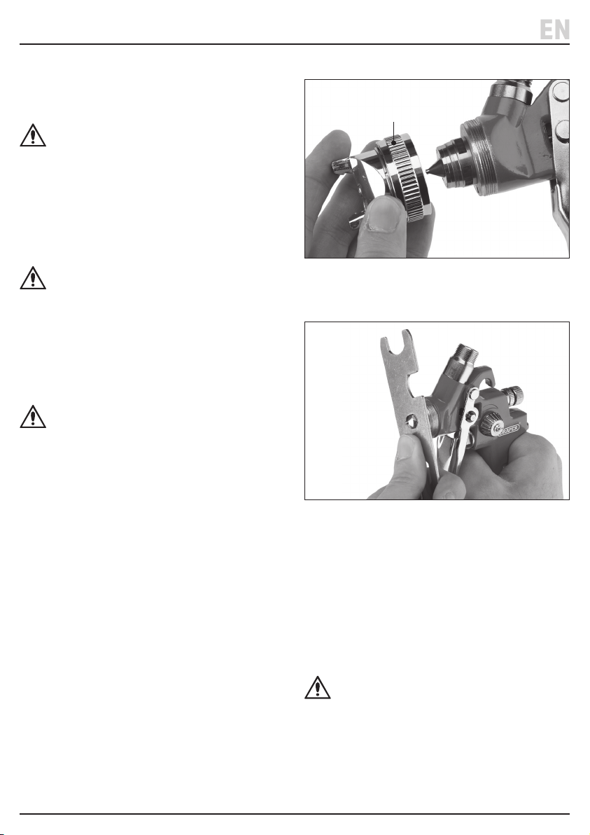
(1)
15 Fig.
a. Twist the air cap (1) anticlockwise to remove
it (Fig. 15).
16 Fig.
b. Use the M12 spanner (F1) (1.4mm) or the M5 ring
spanner (F2) / (G3) (0.8mm) to remove the nozzle
head (20) (Fig. 16).
c. Soak the parts in a solvent to clear clogged holes
or openings, then rinse clean.
d. Clean around the outside of the air cap and nozzle
head using the parts brush (H).
e. Clean the interior of the nozzle head using the
pick-up tube brush (I).
CAUTION! Take great care to avoid damaging
the openings in the air cap and nozzle head
pattern.
– 16 –
Page 17
EN
9. Maintenance and Troubleshooting
4. Clean the uid needle and chamber:
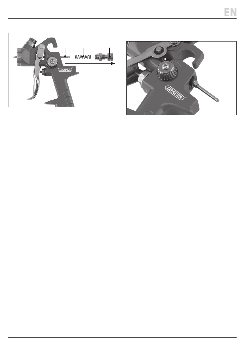
(22) (21) (3)
17 Fig.
a. Rotate the uid control dial (3) anticlockwise until
it comes away from the spray gun body (Fig. 17).
b. Remove the spring (21) and the uid needle (22)
from the chamber via the back of the spray gun.
c. Soak the parts in the solvent and rinse clean.
d. Clean all parts of the uid needle using the parts
brush.
e. Insert the pick-up tube brush into the uid needle
chamber and clean it.
5. Soak the spray gun body in the solvent, then rinse it
clean and brush it with the parts brush.
6. Reassemble the spray gun:
a. Reattach the nozzle head.
(23)
18 Fig.
b. Insert the uid needle point-rst into the chamber
through the back of the spray gun (Fig. 18).
Important: Ensure that the needle point aligns
with and passes through the trigger cylinder (23)
when it is inserted.
c. Pass the spring onto the at end of the uid needle
and screw the uid control dial back into place,
adjusting both parts of the dial to ensure a
comfortable t.
d. Reattach the air cap and test the trigger to ensure
smooth operation.
9.3 Storing the Product
When the spray guns and their accessories are not in use:
a. Switch o and disconnect the air line and detach it
from the regulator.
b. Remove the regulator from the spray gun.
c. Clean the tool thoroughly before storage.
d. Store the product in a clean and dry location, out
of the reach of children.
– 17 –
Page 18

EN
9. Maintenance and Troubleshooting
9.4 Troubleshooting
Problem Possible Cause Remedy
Paint leaks from the nozzle when
not in use.
The spray gun delivers a curved or
one-sided spray pattern.
The spray pattern is too thick. The uid viscosity is too high. Thin the uid as appropriate.
The spray pattern is too thin. The uid viscosity is too low. Thicken the uid as appropriate.
Dust or dirt around the nozzle
opening or uid needle is
preventing an airtight seal with the
paint cup.
The nozzle head or uid needle is
damaged.
The openings in the air cap or
nozzle are clogged or damaged.
The air pressure at the nozzle is too
low.
The uid needle or nozzle head has
become worn and the separation
between them has increased.
The air pressure at the nozzle is too
high.
Clean the uid needle and nozzle
head (see 9.2).
Replace the nozzle head or uid
needle as appropriate. Contact
Draper Tools for repair and
replacement options.
Clean the air cap (see 9.2) and
nozzle or replace the parts if
necessary. Contact Draper Tools for
repair and replacement options.
Increase the air pressure and check
the tool for leaks or blockages.
Replace the nozzle head or uid
needle as appropriate. Contact
Draper Tools for repair and
replacement options.
Decrease the air pressure and check
the tool for blockages.
The spray output splutters or is
inconsistent.
The uid level in the paint cup is
too low.
Air is mixing with the uid due to a
leak or broken seal.
The uid needle does not create a
seal against the inside of the nozzle
head when the trigger is released.
– 18 –
Top up the uid in the paint cup.
Check the tightness of the paint
cup and the uid needle bolt beside
the trigger.
Clean or replace the uid needle
and nozzle head as necessary.
Page 19

EN
9. Maintenance and Troubleshooting
Problem Possible Cause Remedy
The uid in the paint cup bubbles or
boils.
The centre of the spray pattern is
too narrow or the whole pattern is
not wide enough.
Air is leaking from the air cap. The air valve is sticking or bent. Clean the air valve and replace it if it
The tool does not spray the uid. The air pressure at the spray gun is
The paint cup is not sealed or is not
tightly attached to the spray gun.
The spray gun is being held at an
ineective angle.
The openings in the air cap are
clogged or damaged.
The uid viscosity is not appropriate
for the spray gun and must be
adjusted.
The air valve seal or spring is
broken.
too low.
The uid control dial setting is too
low.
The uid is too viscous. Thin the uid as appropriate.
Clean, tighten or replace the paint
cup as appropriate.
Hold the spray gun in a more
upright position.
Clean the air cap (see 9.2) or
replace the part if necessary.
Contact Draper Tools for repair and
replacement options.
Increase the uid viscosity for a
thicker centre; decrease the uid
viscosity for a broader pattern.
is bent or damaged. Contact Draper
Tools for repair and replacement
options.
Replace the parts as necessary.
Contact Draper Tools for repair and
replacement options.
Check and regulate the air pressure
accordingly.
Rotate the uid control dial
clockwise to increase the ow.
The uid level in the paint cup is
too low.
– 19 –
Top up the uid in the paint cup.
Page 20
10. Returns and Disposal
EN
For servicing, repair and replacement options, please
contact the Draper Tools Product Helpline for details of
your nearest authorised agent. Any servicing or repairs
carried out by unauthorised personnel will invalidate
your warranty.
Important: For safety, ALWAYS drain and clean the
product of any oil, fuel, chemicals or other substances
before returning it to Draper Tools or its authorised
agent. Store these materials in suitable containers and
dispose of them in accordance with local regulations.
Draper Tools and its agents cannot be responsible for the
disposal of these substances.
At the end of its working life, dispose of the product
responsibly and in line with local regulations. Recycle
where possible.
Important: Dispose of paint and solvents separately and
in accordance with local regulations. DO NOT abandon
them in the environment.
– 20 –
Page 21
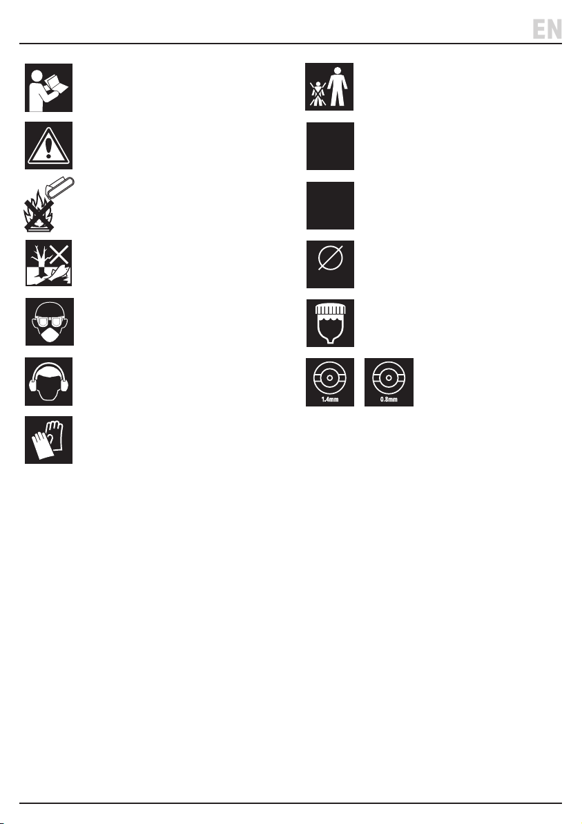
11. Explanation of Symbols
EN
Read the instruction manual
Warning!
Do not incinerate or throw onto re
Do not abandon in the environment
Wear suitable eye protection and
breathing apparatus
Wear ear defenders
Wear protective gloves
1/4"
BSP
50
psi
33mm
600
ml
Keep out of the reach of children
Air inlet
Max. operating air pressure (example)
Air inlet diameter
Max. uid capacity
Supplied air cap sizes
– 21 –
Page 22

Notes
EN
– 22 –
Page 23

Notes
EN
– 23 –
Page 24

Contact Details
Draper Tools
Draper Tools Limited
Hursley Road
Chandler’s Ford
Eastleigh
Hampshire
SO53 1YF
UK
Website: drapertools.com
Email: [email protected]
Product Helpline: +44 (0) 23 8049 4344
Telephone Sales Desk: +44 (0) 23 8049 4333
General Enquiries: +44 (0) 23 8026 6355
General Fax: +44 (0) 23 8026 0784
Please contact the Draper Tools Product Helpline for repair and servicing enquiries.
Delta International
Delta International BV
Oude Graaf 8
6002 NL
Weert
Netherlands
© Published by Draper Tools Limited
 Loading...