

Page 1
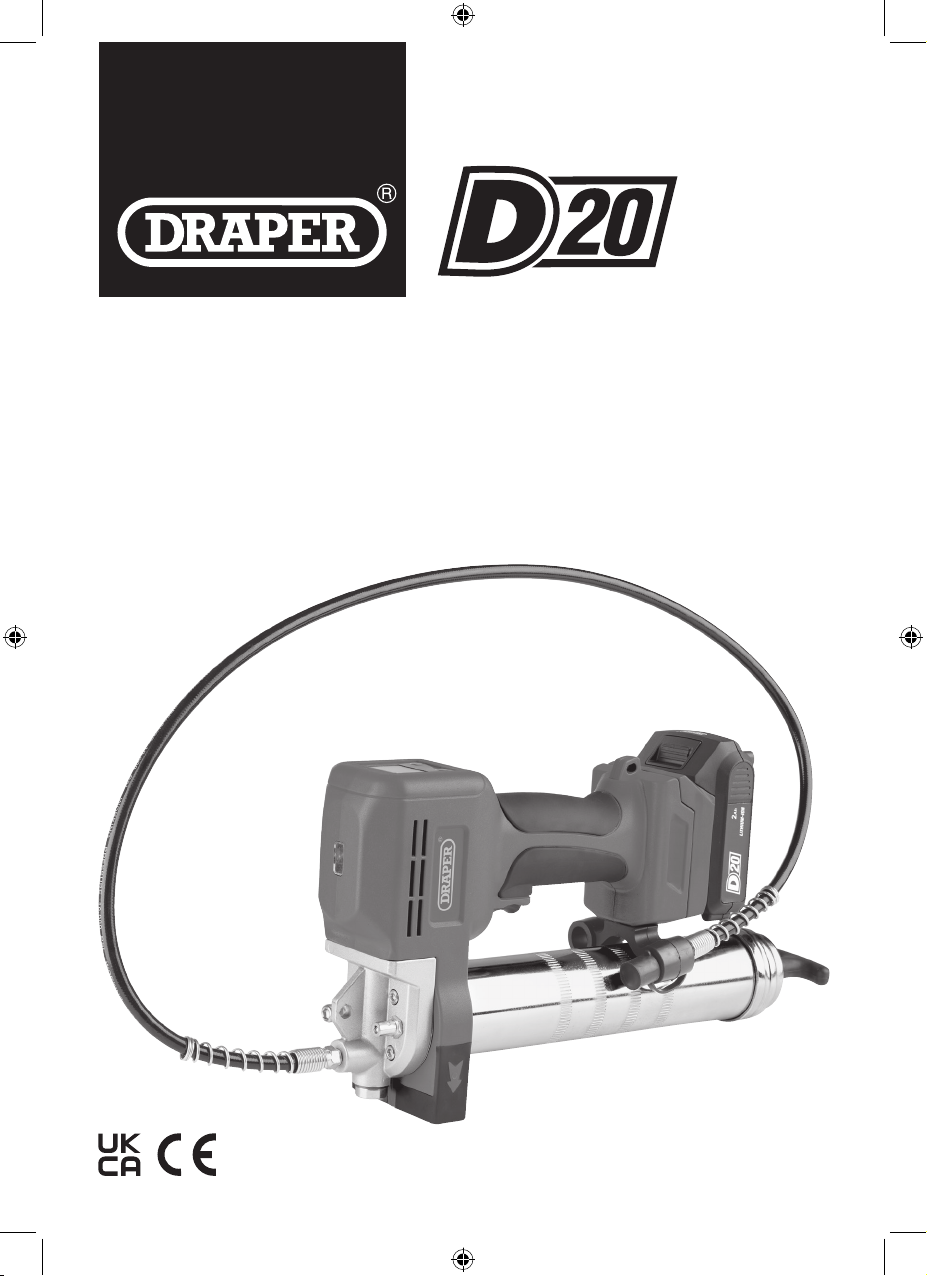
MULTI-TOOL BATTERY SYSTEM
20V
GREASE
GUN
03359, 18097
EN
Original Instructions
Version 2 – August 2023
Page 2
1. Preface
These are the original product instructions. This
document is part of the product; retain it for the life
of the product, passing it on to subsequent holders.
Read this manual in full before attempting to
assemble, operate or maintain this product.
This Draper Tools manual describes the purpose
of the product and contains all the necessary
information to ensure its correct and safe use.
Following all the instructions and guidance in
this manual will ensure the safety of both the
product and the operator and increase the
lifespan of the product.
1.1 Product Reference
User Manual for: D20 20V Cordless Grease Gun
Stock No: 03359, 18097
Part No: D20GGKIT, D20GGB
1.2 Revisions
Version 1: August 2022
First release
Version 2: September 2023
General formatting and content updates. Addition of
Stock number 18066 (bare product)
Please visit drapertools.com/manuals for the latest
version of this manual and the associated parts list, if
applicable.
All photographs and drawings within this manual are
supplied by Draper Tools to help illustrate correct
operation of the product.
Every eort has been made to ensure the
information contained in this manual is accurate.
However, Draper Tools reserves the right to amend
this document without prior warning. Always use the
latest version of the product manual.
1.3 Understanding the Safety Content of
This Manual
WARNING! – Situations or actions that may result
in personal injury or death.
CAUTION! – Situations or actions that may result
in damage to the product or surroundings.
Important: – Information or instructions of particular
importance.
1.4 Copyright © Notice
Copyright © Draper Tools Limited.
Permission is granted to reproduce this manual for
personal and educational use ONLY. Commercial
copying, redistribution, hiring or lending is strictly
prohibited.
No part of this manual may be stored in a retrieval system
or transmitted in any other form or means without written
permission from Draper Tools Limited.
In all cases, this copyright notice must remain intact.
– 2 –
Page 3
2. Contents
EN
1. Preface 2
1.1 Product Reference 2
1.2 Revisions 2
1.3 Understanding the Safety Content of
This Manual 2
1.4 Copyright © Notice 2
2. Contents 3
3. Product Introduction 4
3.1 Scope 4
3.2 Specication 4
4. Health and Safety Information 5
4.1 General Power Tool Safety Warnings 5
4.2 Additional Safety Instructions for
This Grease Gun 6
4.3 Additional Safety Instructions for
Rechargeable Batteries 6
4.4 Connection to the Power Supply (Charger) 7
4.5 Residual Risk 7
5. Identication and Unpacking 8
5.1 Product Overview 8
5.2 What’s in the Box? 9
5.3 Packaging 9
6. Preparing the Battery 10
6.1 Charging the Battery 10
6.2 Inserting and Removing the Battery 11
7. Loading the Grease Gun 12
7.1 Attaching the Hose and Coupler 12
7.2
Installing and Removing a Grease Cartridge
7.3
Filling the Grease Gun From a Bulk Container
7.4 Filling the Grease Gun Using a Filler Pump 14
7.5 Priming the Grease Gun and Expelling
Air Pockets 14
8. Operating Instructions 16
8.1 Operation 16
8.2 The Strap 16
8.3 The Safety Valve 16
9. The Control Panel 17
9.1 Output Selection 17
9.2 LED Worklight 17
9.3 Monitoring Grease Flow 17
9.4 LCD Warning Mode and Safety Cut-Outs 17
10. Maintenance and Troubleshooting 18
12
13
10.1 General Maintenance 18
10.2 Storing the Grease Gun 18
10.3 Battery Care 18
10.4 Troubleshooting 19
11. Warranty 20
12. Spares, Returns and Disposal 21
13. Explanation of Symbols 22
Notes 23
– 3 –
Page 4
3. Product Introduction
3.1 Scope
This product is designed for the application of
lubrication to xtures and ttings and can be loaded via
cartridges or from bulk. Outputs and diagnostics are
indicated on an LCD display.
Important: This product is suitable for use with standard
lithium-based lubricants (NLGI grades 2 and 3) ONLY. DO
NOT use this product to dispense water, adhesives or
corrosive substances.
3.2 Specication
Stock No(s). 03359,18097 (bare product)
Part No(s). D20GGKIT, D20GGB (bare product)
Rated voltage: 20V DC
High output mode:
Max. pressure: 10,000psi (689.5bar)
Max. ow rate: 140g/min
Low output mode:
Max. pressure: 6,000psi (413.7bar)
Max. ow rate: 100g/min
Operating temperature: -10 to +40°C
Capacities:
Cartridge: 400g, Ø54mm
Bulk: 450g
Sound pressure level: <70dB(A)
Vibration: <2.3m/s
Hose length: 1.06m
Net weight: 2.82kg
2
This product is part of the D20 multi-tool battery system
and is suitable for regular use by enthusiasts and
tradespersons alike.
WARNING! This product is not a toy and must be
respected.
Read this manual in full before attempting to assemble,
operate or maintain the product and retain it for later use.
Charger
Stock No.: 97914
Part No.: D20BSC/2
Applicable batteries: 55887
00649
55898
55907
Charging times: 2.0Ah: 55 minutes
3.0Ah: 85 minutes
4.0Ah: 110 minutes
5.0Ah: 150 minutes
Rated voltage: 230V AC
Rated frequency: 50–60Hz
Rated output: 70W
Rated DC output voltage: 20V
Rated DC output current: 2.4A
Protective device rated current: 8A
Construction: Class II
Net weight: 0.42kg
Important: The declared vibration total values and noise
emissions values have been measured in accordance
with a standard test method and may be used for
comparing one tool with another. These values may also
be used in a preliminary assessment of exposure.
WARNING! The vibration and noise emissions
during actual use of the product can dier from
the declared values depending on the mode
selected and the workpiece upon which it is
used. Before each use, estimate the likely
exposure resulting from the actual conditions of
use. Take into account all parts of the operation
cycle in order to identify any safety measures
required to protect the operator.
Battery
Stock No.: 55887
Part No.: D20B2.0AH
Type: Li-ion
Rated voltage: 20V
Rating: 2.0Ah
Suitable ambient conditions:
Temperature during operation: -15 to 50°C
Temperature during charging: 4 to 40°C
Temperature during storage: 0 to 45°C
– 4 –
Page 5
4. Health and Safety Information
Important: Read all the Health and Safety instructions
before attempting to operate, maintain or repair this
product. Non-compliance with these instructions may
result in injury or damage to the user or the product.
4.1 General Power Tool Safety Warnings
WARNING! Read all safety warnings,
instructions, illustrations and specications
provided with this power tool. Failure to follow all
instructions listed below may result in electric
shock, re and/or serious injury.
Save all warnings and instructions for future reference.
The term “power tool” in the warnings refers to your
mains-operated (corded) power tool or battery-operated
(cordless) power tool.
Work area safety
• Keep work area clean and well lit.
− Cluttered or dark areas invite accidents.
• Do not operate power tools in explosive atmospheres,
such as in the presence of ammable liquids, gases or
dust.
− Power tools create sparks which may ignite the
dust or fumes.
• Keep children and bystanders away while operating a
power tool.
− Distractions can cause you to lose control.
Electrical safety
• Power tool plugs must match the outlet. Never modify
the plug in any way. Do not use any adapter plugs with
earthed (grounded) power tools.
− Unmodied plugs and matching outlets will
reduce the risk of electric shock.
• Avoid body contact with earthed or grounded
surfaces, such as pipes, radiators, ranges and
refrigerators.
− There is an increased risk of electric shock if your
body is earthed or grounded.
• Do not expose power tools to rain or wet conditions.
− Water entering a power tool will increase the risk
of electric shock.
• Do not abuse the cord. Never use the cord for
carrying, pulling or unplugging the power tool. Keep
cord away from heat, oil, sharp edges or moving parts.
− Damaged or entangled cords increase the risk of
electric shock.
• When operating a power tool outdoors, use an
extension cord suitable for outdoor use.
− Use of a cord suitable for outdoor use reduces the
risk of electric shock.
• If operating a power tool in a damp location is
unavoidable, use a residual current device (RCD)
protected supply.
− Use of an RCD reduces the risk of electric shock.
Personal safety
• Stay alert, watch what you are doing and use common
sense when operating a power tool. Do not use a
power tool while you are tired or under the inuence
of drugs, alcohol or medication.
− A moment of inattention while operating power
tools may result in serious personal injury.
• Use personal protective equipment. Always wear eye
protection.
− Protective equipment such as a dust mask,
non-skid safety shoes, hard hat or hearing
protection use for appropriate conditions will
reduce personal injuries.
• Prevent unintentional starting. Ensure the switch is in
the o-position before connecting to a power source
and/or battery pack or picking up or carrying the tool.
− Carrying power tools with your nger on the
switch or energising power tools that have the
switch on invites accidents.
• Remove any adjusting key or wrench before turning
the power tool on.
− A wrench or a key left attached to a rotating part
of the power tool may result in personal injury.
• Do not overreach. Keep proper footing and balance at
all times.
− This enables better control of the power tool in
unexpected situations.
• Dress properly. Do not wear loose clothing or
jewellery. Keep your hair and clothing away from
moving parts.
− Loose clothes, jewellery or long hair can be
caught in moving parts.
• If devices are provided for the connection of dust
extraction and collection facilities, ensure these are
connected and properly used.
− Use of dust collection can reduce dust-related
hazards.
– 5 –
Page 6
4. Health and Safety Information
• Do not let familiarity gained from frequent use of tools
allow you to become complacent and ignore tool
safety principles.
− A careless action can cause severe injury within a
fraction of a second.
Power tool use and care
• Do not force the power tool. Use the correct power
tool for your application.
− The correct power tool will do the job better and
safer at the rate for which it was designed.
• Do not use the power tool if the switch does not turn it
on and o.
− Any power tool that cannot be controlled with the
switch is dangerous and must be repaired.
• Disconnect the plug from the power source and/or
remove the battery pack, if detachable, from the
power tool before making any adjustments, changing
accessories or storing power tools.
− Such preventive safety measures reduce the risk
of starting the power tool accidentally.
• Store idle power tools out of the reach of children and
do not allow persons unfamiliar with the power tool or
these instructions to operate the power tool.
− Power tools are dangerous in the hands of
untrained users.
• Maintain power tools and accessories. Check for
misalignment or binding of moving parts, breakage of
parts and any other condition that may aect the
power tool’s operation. If damaged, have the power
tool repaired before use.
− Many accidents are caused by poorly maintained
power tools.
• Keep cutting tools sharp and clean.
− Properly maintained cutting tools with sharp
cutting edges are less likely to bind and are easier
to control.
• Use the power tool, accessories and tool bits, etc., in
accordance with these instructions, taking into
account the working conditions and the work to be
performed.
− Use of the power tool for operations dierent from
those intended could result in a hazardous
situation.
• Keep handles and grasping surfaces dry, clean and
free from oil and grease.
− Slippery handles and grasping surfaces do not
allow for safe handling and control of the tool in
unexpected situations.
Service
• Have your power tool serviced by a qualied repair
person using only identical replacement parts.
− This will ensure that the safety of the power tool is
maintained.
4.2 Additional Safety Instructions for This
Grease Gun
• Use this product ONLY with the hose supplied.
− If the hose becomes damaged, contact Draper
Tools for replacement options.
• Have the hose replaced immediately if it shows signs
of wear, kinks or damage to the exterior.
• NEVER carry this product by the hose.
• This product can generate pressure up to 10,000psi;
ALWAY S wear eye protection.
• Keep hands clear of the rubber parts of the hose
during use.
• If the tool or target grease point has become jammed,
release the trigger and investigate the blockage.
− DO NOT continue to depress the trigger as this
may damage the tool or the battery.
Important: Read and understand the safety information
and instructions for any lubricant product before using it
with this tool.
WARNING! Lubricants may be highly ammable.
Keep this product and any lubricants away from
open ames, sparks and other sources of heat.
DO NOT use ammable lubricants in this tool.
4.3 Additional Safety Instructions for
Rechargeable Batteries
Important: Use ONLY the Draper Tools D20 range
battery pack and charger supplied with this product. DO
NOT use this charger with any batteries that are not part
of the Draper Tools D20 range.
WARNING! DO NOT use or charge the battery if
leakage is evident.
Chargers
WARNING! NEVER charge non-rechargeable or
damaged batteries.
• The supplied charger is for indoor use ONLY.
• Before connecting the charger to the power supply,
check that the plug, cable and charger casing are in
good condition and have any damaged part
immediately repaired by a suitably qualied person.
– 6 –
Page 7
4. Health and Safety Information
EN
• Connect the supplied charger to a rated mains outlet
ONLY.
− DO NOT plug the charger into site generators,
engine generators or DC power sources.
• ALWAY S disconnect the charger from the power
supply before removing the battery.
• Charge the battery in a dry and well-ventilated
environment in ambient temperatures between 5 and
40°C, ensuring that the ventilation slots on the
charger casing are not obstructed.
• DO NOT short-circuit the battery by connecting the
positive and negative terminals while it is outside of
the product.
− Keep the battery away from metallic objects that
may inadvertently allow connection of the
terminals.
• The supplied charger is a Class II appliance.
Batteries
• DO NOT open, crush or burn the battery as this may
release potentially harmful chemicals.
• DO NOT expose the battery to temperatures greater
than 50°C.
• DO NOT attempt to charge batteries that exhibit a
temperature that is not between 5 and 30°C.
− Allow batteries that are too hot or too cold to
normalise before charging.
• DO NOT expose the battery pack to rain or other wet
conditions.
• ALWAY S remove the battery before storing the
product for extended periods.
• ALWAY S remove the battery from the tool before
recycling and dispose of it in accordance with local
regulations.
• If a re occurs, use a CO
WARNING! The electrolyte in this battery pack
is corrosive. Avoid contact with skin.
If contact occurs, ush the area with clean water
and pat it dry. Seek medical attention at the
earliest opportunity and inform the responder
that the contaminant is a “high-alkaline corrosive
liquid”. If contact with the eyes occurs, ush
immediately with plenty of water ONLY and seek
medical advice at the earliest opportunity.
2
or dry chemical extinguisher.
4.4 Connection to the Power Supply
(Charger)
This appliance is supplied with an approved plug and
cable for your safety.
If the power supply cord is damaged, it must be replaced
by Draper Tools, an authorised service agent or similarly
qualied personnel in order to avoid a hazard.
The damaged or incomplete plug, when cut from the
cable, shall be disabled to prevent connection to a live
electrical outlet.
This product and its charger are Class II* appliances and
are designed for connection to a power supply matching
that detailed on the rating label and compatible with the
plug tted.
The fuse in the power supply for this product cannot be
replaced. Contact Draper Tools for replacement options
if the fuse in the supplied plug has blown.
If an extension lead is required, use an approved and
compatible lead rated for this appliance.
Follow all the instructions supplied with the extension
lead.
Important: Always follow the extension lead instructions
regarding maximum load while the cable is wound. If in
doubt, unwind the entire cable. A coiled extension lead
generates heat which could melt the lead and cause a
re.
*Double insulated: This product is double insulated and
does not require an earth connection to protect against
electric shock from accessible conductive parts in the
event of failure of the basic insulation.
4.5 Residual Risk
The safety instructions in this manual cannot account for
all possible conditions and situations that may occur.
Exercise common sense and caution when using this
product and protect against any additional conceivable
risks.
– 7 –
Page 8
5. Identication and Unpacking
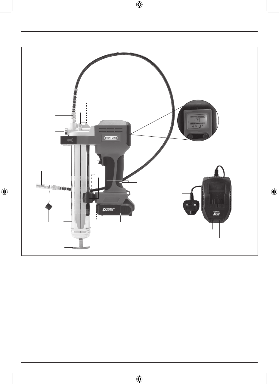
5.1 Product Overview
(4)
(13)
(1)
(18)
(9)
(19)
(13)
(15)
(14)
(11)
(5)
(only supplied with 03359)
(10)
(22)
(3)
(8)
(12)
(16)
(1) Air vent valve
(2) Battery charge indicators
(3) Battery release button
(4) Bulk ller nipple
(5) Control panel
(6) Charge indicator button
(7) D20 battery pack (2.0Ah) (only supplied
with 03359)
(8) Grease tube
(9) Grease tube head
(10) Grips
(11) Hose
(2, 6)
(17)
(7)
(12) Hose cap
(13) Hose coupler
(14) Hose coupler holders
(15) LED worklight
(16) Plunger handle
(17) Plunger rod
(18) Safety valve
(19) Trigger switch
(20) Power indicator (red)
(21) Charging indicator (green)
(22) Power cable and plug
– 8 –
(20)
(21)
Page 9
5. Identication and Unpacking
EN
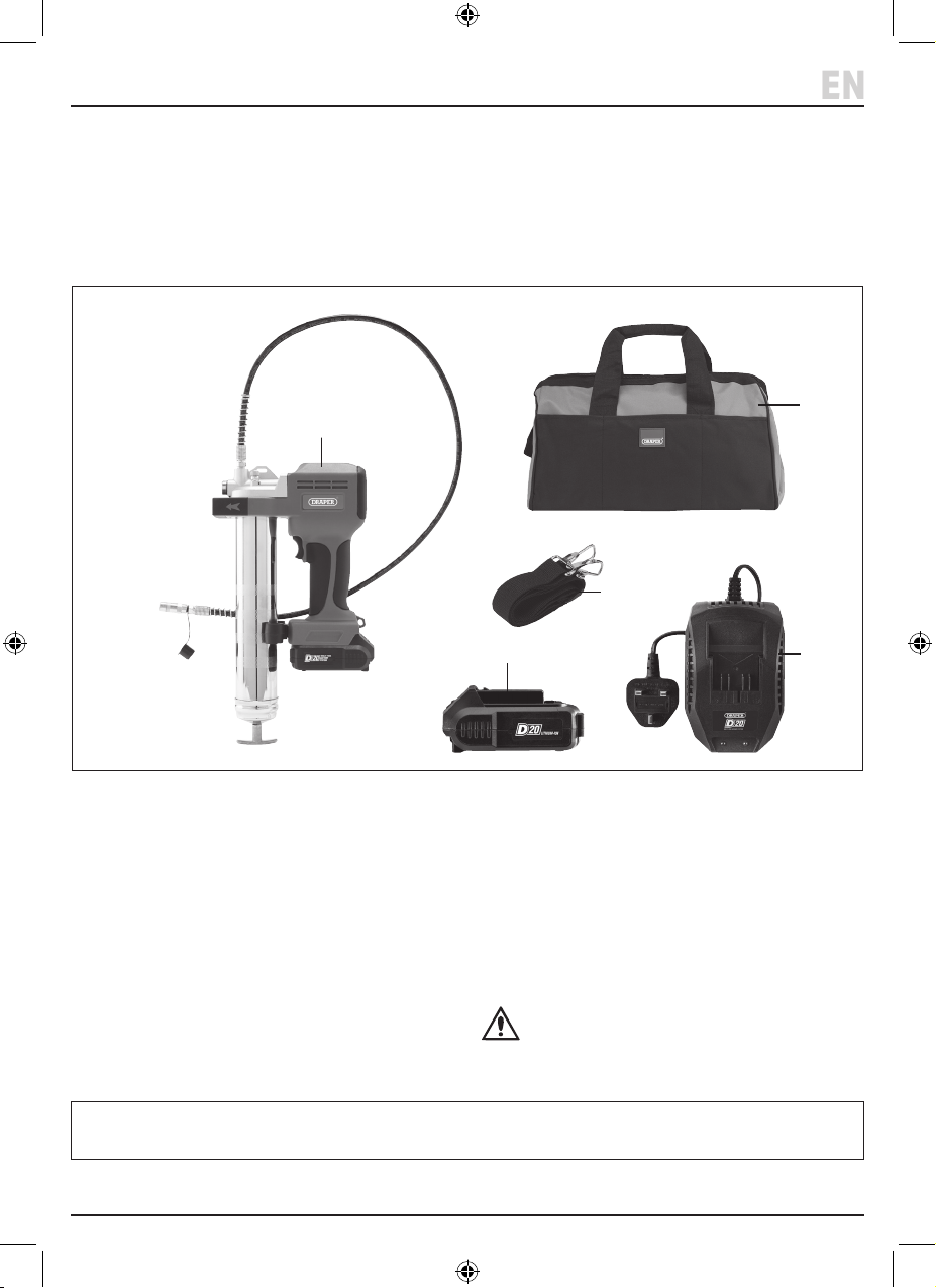
5.2 What’s in the Box?
Carefully remove the product from the packaging and
examine it for any signs of damage that may have
occurred during shipment.
(A)
Before assembling the product, lay the contents out and
check them against the parts shown below. If any part is
damaged or missing, do not attempt to use the product.
Please contact the Draper Helpline; contact details can
be found at the back of this manual.
(D)
(E)
(B) (C)
(A) 1 x Grease gun
(B) 1 x 2.0Ah D20 battery pack (03359 only)
(C) 1 x D20 battery charger (03359 only)
(D) 1 x Canvas bag (03359 only)
(E) 1 x Strap (03359 only)
5.3 Packaging
Keep the product packaging for the duration of the
warranty period for reference should the product need to
be returned for repair.
Please visit drapertools.com for our full range of accessories and consumables.
WARNING! Keep packaging materials out of
reach of children. Dispose of packaging
correctly and responsibly and in accordance
with local regulations.
– 9 –
Page 10
6. Preparing the Battery
Important: Read all the health and safety instructions
listed in this manual before attempting to use the
product. DO NOT make any adjustments to the product
while the trigger switch is depressed.
6.1 Charging the Battery
CAUTION! ALWAYS ensure that the output
voltage of the charger matches the voltage of
the battery pack before use. Ensure that both
the battery pack and charger are not damaged
in any way. NEVER charge or use a damaged
battery or charger; contact Draper Tools for
support.
Important: Stock No.03359 is supplied with the
appropriate battery and charger. DO NOT use any other
charger to charger batteries for use with this product.
Similarly, for the ‘bare’ version of this product (Stock
No.18097) ONLY use the appropriate batteries and
chargers from the Draper Tools D20 range.
Important: This battery is supplied without charge and
MUST be charged for at least 90 minutes before rst use.
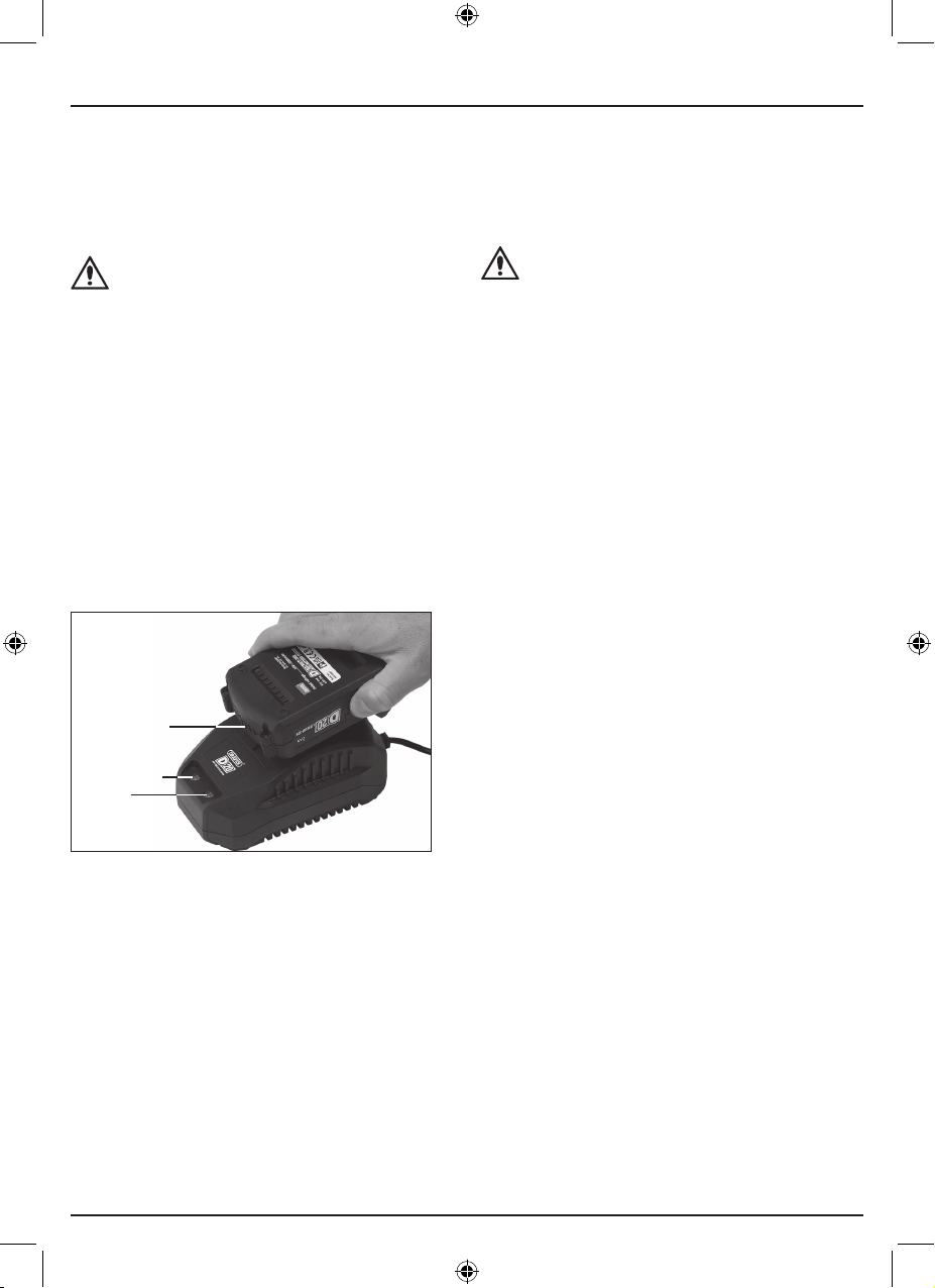
5. When charging is complete, the charging indicator
stays illuminated and the power indicator goes out.
6. To remove the battery pack from the charger, press
the battery release button (3) and slide the battery
away.
CAUTION! The battery and charger may be hot
after extended periods of charging. Disconnect
the power supply and allow the battery and
charger to cool before attempting to remove the
battery. Allow at least 15 minutes before reusing
the battery charger.
If the power indicator begins to ash during charging,
there may be a problem with the battery. Remove the
battery and check for obstructions and debris around the
charging contacts. If the problem is not resolved, stop
charging the battery immediately and contact Draper
Tools for support.
(2)
(20)
(21)
1 Fig.
1. Remove the battery from the tool; see 7.2 Inserting
and Removing the Battery.
2. Connect the charger power cable to a power supply.
The red power indicator (20) illuminates when the
charger is powered.
3. Slide the battery into the charger until it clicks.
The green charging indicator (21) ashes to indicate
that the battery is charging.
4. The current charge level of the battery pack is shown
by the battery charge indicators (2) on the front of the
battery base; a greater number of illuminated LEDs
indicates a greater level of charge.
– 10 –
Page 11
6. Preparing the Battery
EN
6.2 Inserting and Removing the Battery
Important: ONLY use this tool with batteries and
chargers from the Draper Tools D20 range. Read all the
safety and operation instructions provided with these
parts before use.
Important: ALWAYS ensure that the trigger switch is
NOT depressed when inserting or removing the battery.
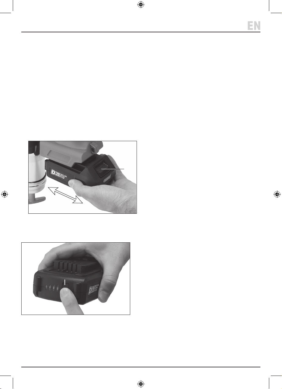
• To install a battery pack (B), slide the contacts into the
base of the grease gun until it clicks into place.
Important: DO NOT force the battery, and ensure it is
rmly secured before use.
• To remove a battery pack, press and hold the battery
release button (3) and slide the battery away from the
tool.
(3)
2 Fig.
To view the battery charge on the battery itself, press the
charge indicator button (6) at any time.
(6)
3 Fig.
– 11 –
Page 12
7. Loading the Grease Gun
The grease gun can be loaded using several methods to
best suit the resources available.
Important: ALWAYS ensure that the air vent valve (1) is
tightened before loading the grease gun, regardless of
method.
CAUTION! The grease gun may be loaded with
lubricants rated to NLGI numbers 2 or 3 ONLY.
DO NOT load water, adhesives or corrosive
liquids into the grease tube.
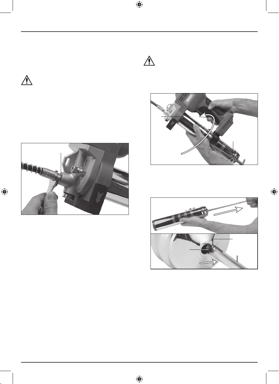
7.1 Attaching the Hose and Coupler
The hose and coupler are installed before shipment.
The hose (11) should be attached to the hose connection
(23) on the top of the tool body and tightly secured using
a spanner or other tool.
(23)
7.2 Installing and Removing a Grease
Cartridge
CAUTION! NEVER install crushed or notched
cartridges into the grease tube.
To install a cartridge:
1. Unscrew and remove the grease tube (8) from the
grease tube head (9).
(9)
(8)
5 Fig.
2. Pull the plunger handle (16) outward until it is fully
extended and latch the plunger rod locking groove
(24) into the plunger lock slot (25).
4 Fig.
If it has been removed, rmly attach the hose coupler
(13) to the other end of the hose, leaving the hose cap in
place until the tool is ready for use.
– 12 –
(25)
(24)
6 Fig.
(17)
Page 13
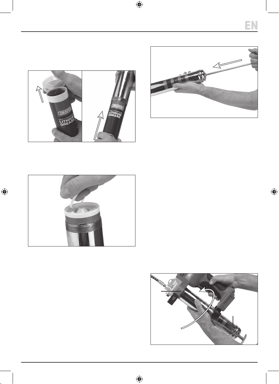
7. Loading the Grease Gun
EN
3. Remove the plastic cap from the cartridge and twist
the open end into the grease tube.
Important: DO NOT dispose of the cartridge caps
until the cartridge is empty in case it must be stored
in a partially used state.
7 Fig.
4. Remove the ring-pull seal from the other end of the
cartridge and screw the grease tube tightly back into
the grease tube head.
6. Slide the rod all the way into the grease tube.
9 Fig.
7. Reset the control panel display; see 10.3 Monitoring
Grease Flow.
To remove a cartridge:
1. Loosen the grease tube by one turn and pull the
plunger handle until it is fully extended.
2. Unscrew the grease tube from the grease tube head
and pull the cartridge out of the open end of the tube.
Grease cartridges with a smaller thread can screw
directly into the grease tube head.
Dispose of old cartridges responsibly and in accordance
with local regulations.
8 Fig.
5. Prime the grease gun; see 8.5 Priming the Grease
Gun and Expelling Air Pockets.
7.3 Filling the Grease Gun From a Bulk
Container
Important: This method of loading is particularly
susceptible to contamination of the lubricant and grease
tube. Take extra care to maintain a clean environment
and prevent contamination when loading in this way.
1. Unscrew and remove the grease tube (8) from the
grease tube head (9).
(9)
(8)
Fig.
– 13 –
10
Page 14

7. Loading the Grease Gun
2. Ensure that the open end of the grease tube is free
from any dust or debris, and push the plunger handle
inwards as far as possible.
11 Fig.
3. Ensure that the open end of the grease tube is free
from any dust or debris, and push the plunger handle
inwards as far as possible.
4. Fully insert the open end of the grease tube into the
lubricant.
5. Slowly pull the plunger handle outwards until it is
fully drawn, ensuring that the end of the tube is
completely covered at all times.
Important: If a break in the suction occurs at any
time during loading, empty the tube into the
container and begin loading again.
(25)
(24)
(17)
8. Prime the grease gun; see 8.5 Priming the Grease
Gun and Expelling Air Pockets.
9. Slide the rod all the way into the grease tube.
10. Reset the control panel display; see 10.3 Using the
Control Panel.
7.4 Filling the Grease Gun Using a Filler
Pump
Important: A ller pump (not supplied) must be tted to
the bulk container in order to use this method to load the
grease gun.
1. Push the handle inwards as far as possible.
2. Insert the bulk ller nipple into the ller pump socket.
3. Operate the bulk ller until the plunger rod locking
groove (24) aligns with the locking slot (25).
CAUTION!
DO NOT overll the grease tube.
4. Release the plunger rod from the locking slot and
slide the rod all the way into the grease tube.
5. Reset the control panel display; see 10.3 Monitoring
Grease Flow.
7.5 Priming the Grease Gun and Expelling
Air Pockets
Important: The grease gun must be primed every time
the grease gun is loaded in order to purge any air pockets
from the grease tube. The battery pack must be installed
in order to fully prime the tool.
This process can be used to prime the tool after loading
and to expel air pockets that may form during use.
1. Load the grease gun using the chosen method and
ensure that the plunger rod (17) is fully extended and
locked into place.
12 Fig.
6. When the plunger rod (17) is fully extended, latch the
groove (24) into the plunger lock slot (25) and wipe
away any excess grease from the open end of the
tube.
7. Screw the grease tube tightly back into the grease
tube head and clean any excess grease from the
grease tube exterior.
– 14 –
Page 15
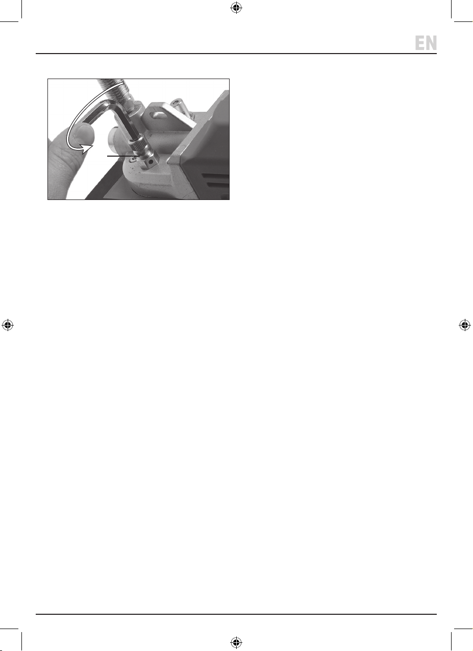
7. Loading the Grease Gun
EN
2. Loosen the air vent valve (1) by a couple of turns.
(1)
13 Fig.
3. Release the plunger rod from the lock slot (25) and
apply pressure to the handle until grease is expelled
from the opening.
4. If grease is not expelled, tighten the air vent valve and
repeat this process several times.
Important: If, after several attempts, grease is not
expelled from the valve, remove the grease tube,
manually pack the inside of the tube head (9) with
grease and then try again.
5. Tighten the air vent valve securely and squeeze the
trigger switch (19) until grease is expelled from the
hose.
Air pockets may be created during operation and cause
the tool to lose pressure. The priming process can also be
completed by loosening the grease tube by one full turn
instead of opening the air vent valve and following the
same procedure.
Important: Before use, read and understand all the
safety instructions listed in this manual. ALWAYS ensure
that the grease gun is primed before operation.
– 15 –
Page 16
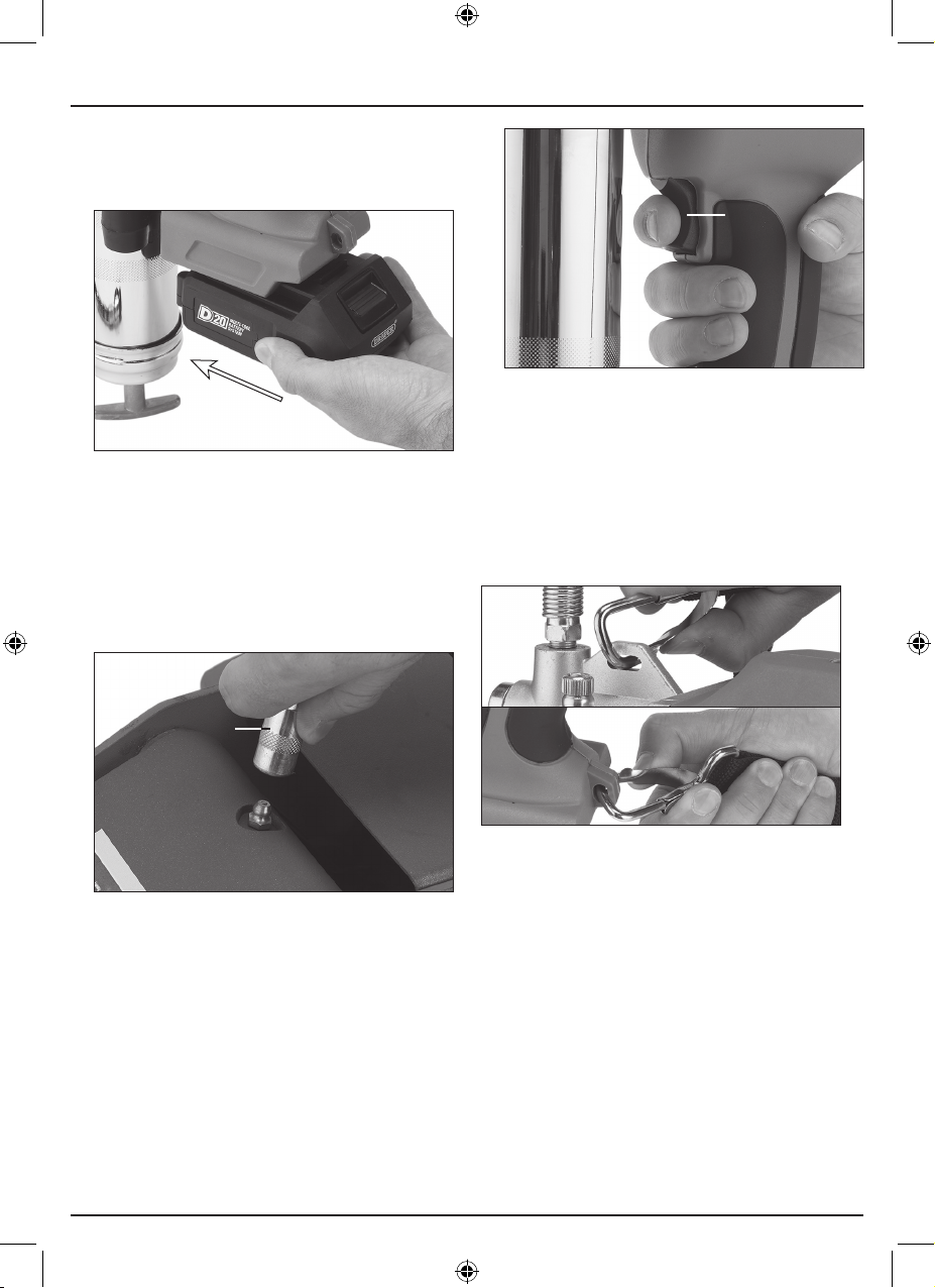
8. Operating Instructions
8.1 Operation
1. Insert a suitable battery pack (see 7.2 Inserting and
Removing the Battery).
14 Fig.
2. Set the output mode as required (see 10.1 Output
Selection).
3. Remove the hose cap (12) and attach the hose
coupler (13) to an appropriate grease tting.
Important: Ensure that the coupler ts snugly around
the grease tting and hold it in place to prevent
disconnection
(19)
16 Fig.
5. Remove the hose coupler from the grease tting.
Important: DO NOT pull on the hose to disconnect
the coupler.
8.2 The Strap
The grease gun can be used with the strap supplied for
hands-free transportation during use. Attach the strap
clips to the top and bottom loops of the grease bun body.
(13)
15 Fig.
4. Squeeze the trigger switch (19) to dispense the
lubricant.
17 Fig.
8.3 The Safety Valve
The safety valve (18) is preset at 10,000psi (±1,000psi)
before shipment. If this pressure level is reached, the
grease gun will not dispense grease.
If this occurs, clean around the safety valve and check for
blockages and debris in the grease tube (8), grease tube
head (9) and hose (11) and ensure that the target bearing
is not clogged. Blockages within the grease gun can also
be cleared by fully loosening the air vent valve (1) and
using a brush to clean inside the opening.
Important: DO NOT adjust this valve under any
circumstances. Doing so will not improve the grease gun
performance, will invalidate your warranty and may lead
to injury.
– 16 –
Page 17
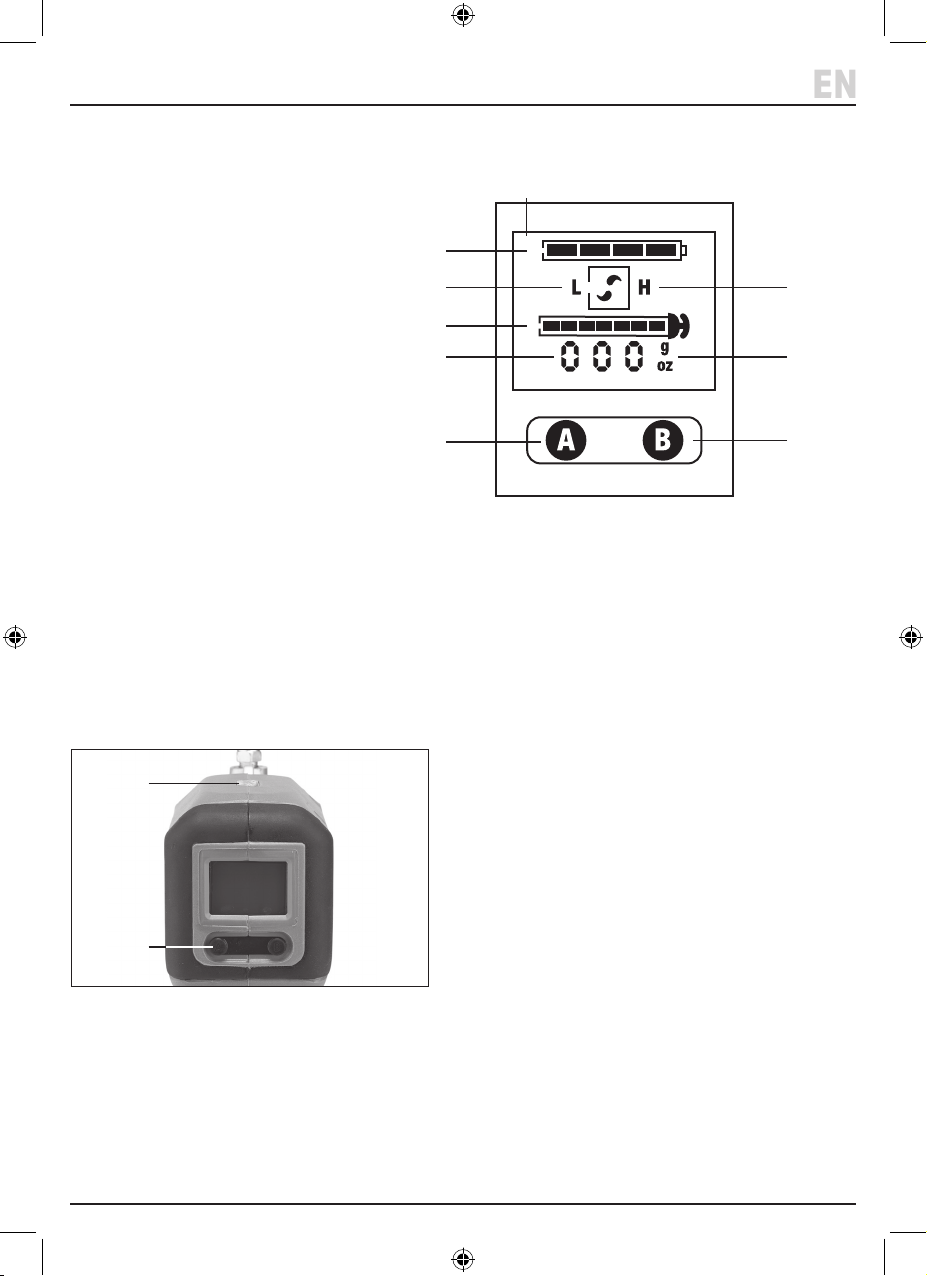
9. The Control Panel
EN
The LCD display illuminates automatically when the trigger switch is depressed and switches o after 20 seconds of
inactivity. The tool battery level is displayed at the top of the display.
(26)
26. LCD display
27. Battery level
28. High output mode
29. Low output mode
30. Remaining grease level
31. Grease output reading
32. Grease output units
33. Button A
34. Button B
(27)
(29)
(30)
(31)
(33)
(28)
(32)
(34)
9.1 Output Selection
The grease gun can be programmed to operate in either
low or high output mode.
To switch between output modes, press and release
button B (34). The active mode is shown on the LCD
display (28) (29).
9.2 LED Worklight
(15)
(33)
19 Fig.
The grease gun is tted with an LED worklight (15) that
can be switched on and o as required.
To switch on the worklight, press and release button A
(33). Press the button again to switch o the light.
9.3 Monitoring Grease Flow
The LCD display indicates how much lubricant has been
dispensed since the reading was last reset. This value can
be displayed in either grams (g) or ounces (oz).
To switch between measurement units, press and hold
button A (33) for up to ten seconds. To reset the reading,
press and hold button B (34) for up to ten seconds.
An approximate indication of the remaining lubricant is
also displayed. When no more grease is available in the
tube, the LCD display enters warning mode; see 10.4
LCD Warning Mode and Safety Cut-Outs.
9.4 LCD Warning Mode and Safety CutOuts
The grease gun will automatically detect the following
issues:
• The tool is drawing more than 40A of current from the
battery.
• An air pocket in the grease tube is preventing the tool
from functioning.
When these issues occur, the LCD display ashes red and
the motor stops automatically. Check the hose, grease
tube and grease tube head for blockages and expel any
air pockets that have accumulated.
– 17 –
Page 18

10. Maintenance and Troubleshooting
Important: Read all the health and safety information
before attempting to maintain or repair this product.
ALWAY S remove the battery before performing any
maintenance.
10.1 General Maintenance
• Clean the tool thoroughly after each use and before
storing it for extended periods.
− Wipe away as much grease as possible from the
tool exterior using a dry cloth.
− Remove the grease tube and clear any residual
grease from the grease tube head.
− DO NOT use solvents or aggressive chemicals to
clean the tool body as these substances may
damage plastic parts.
− Penetrating oils can be injected into the tool head
to help remove trapped grease within the
mechanism.
• Keep the grease tube, grease tube head and hose
assembly clean and free from debris.
• ALWAY S empty or unload the tool before storing it for
longer periods as lubricants may separate and
damage the internal workings of the tool.
• ALWAY S remove the battery pack from the tool when
it is not in use.
10.2 Storing the Grease Gun
• Clean the tool and hose assembly thoroughly before
storing it for extended periods.
• Remove the battery pack and empty any lubricants
before storing the products.
• Store any open grease cartridges separately with both
ends covered.
Important: Take care not to allow dust or debris to
contaminate an open cartridge. DO NOT return
bulk-loaded grease to its original container once it
has been loaded.
• Store the product in a clean and dry location, away
from direct sunlight and out of reach of children.
Important: Prolonged exposure to sunlight or warm
temperatures may cause residual lubricants to
separate and damage the electrical components of
the tool.
• When stored for extended periods, charge the battery
periodically to maintain its health.
10.3 Battery Care
• Avoid allowing the battery pack to become completely
exhausted before recharging.
− When the tool power becomes noticeably weaker,
stop using the tool and recharge the battery pack.
Important: Continuing to use the tool with a low
charge may permanently damage the battery.
• Avoid charging the battery at high temperatures and
allow it to cool after use before recharging.
− Charging a battery while it is warm may damage
its internal components and reduce its operational
lifespan.
− The battery pack should only be used or charged
when its temperature is between 5 and 30°C.
• If neither of the charger indicators (20) (21)
illuminates when the charger is connected to an
active power supply and a battery is connected,
disconnect the charger IMMEDIATELY and have it
replaced or repaired.
– 18 –
Page 19
10. Maintenance and Troubleshooting
EN
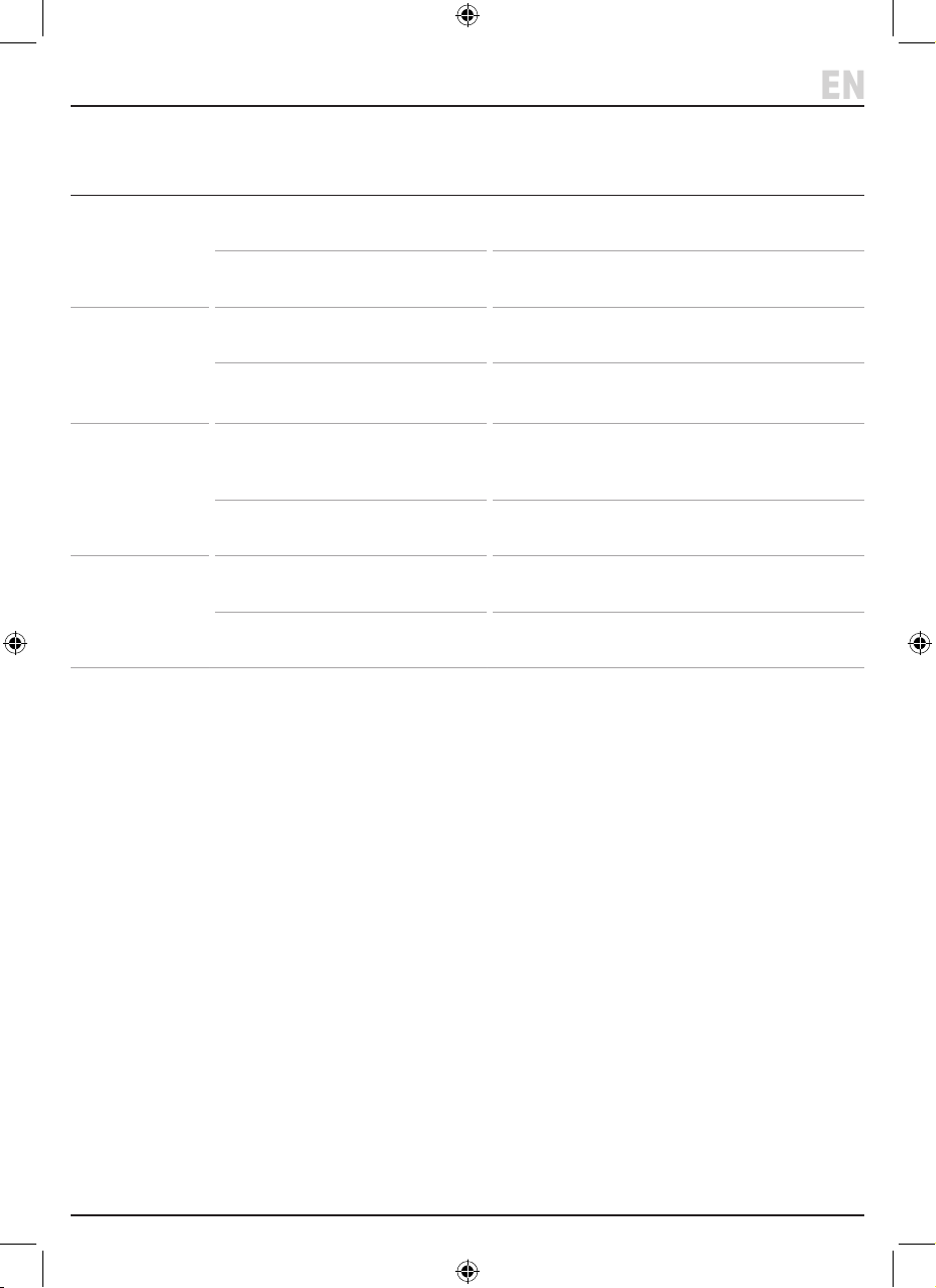
10.4 Troubleshooting
Problem Possible Cause Remedy
The motor does
not start when
the trigger is
depressed.
The grease gun
does not expel
grease when the
trigger switch is
depressed.
The grease gun
continues to fail
even after
priming.
The battery will
not charge or
cannot hold its
charge.
The battery is not charged or is not
attached.
The motor connection has developed
a fault.
The loaded lubricant is exhausted. Reload the grease tube using the desired method
The tool has not been primed or an air
pocket has accumulated.
Air is trapped in multiple places in the
mechanism, or the plunger follower is
binding inside the grease tube.
The lubricant has separated and is no
longer usable
The power supply to the charger is
inactive or faulty.
The battery or charger has developed
a fault.
Charge and attach the battery (see 7.1 and 7.2).
Contact Draper Tools for repair and replacement
options.
(see 8).
Prime the tool to expel any collected air (see 8.5).
Empty and thoroughly clean the tool to ensure all
contaminants and air pockets have been purged.
Then reload and retry.
Empty and clean the tool IMMEDIATELY to prevent
any oil from accessing the electric controls.
Check the charger power connection.
Contact Draper Tools for replacement and repair
options.
– 19 –
Page 20

11. Warranty
Draper power tools have been carefully tested & inspected and are guaranteed to be free from defective materials or
workmanship.
For details of warranty and terms and conditions please visit the Draper Tools website at
www.drapertools.com/warranty
– 20 –
Page 21
12. Spares, Returns and Disposal
EN
For spare parts, servicing, and repair and replacement
options, please contact the Draper Tools Product
Helpline for details of your nearest authorised agent.
Draper Tools will endeavour to hold any spare parts, if
applicable, for seven years from the date that it sells the
nal matching stock item.
Any servicing or repairs carried out by unauthorised
personnel or installation of spare parts not supplied by
Draper Tools will invalidate your warranty.
Important: For safety, ALWAYS drain and clean the
product of any grease or other substances before
returning it to Draper Tools or its authorised agent. Store
these materials in suitable containers and dispose of
them in accordance with local regulations. Draper Tools
and its agents cannot be responsible for the disposal of
these substances.
At the end of its working life, dispose of the product
responsibly and in line with local regulations. Recycle
where possible.
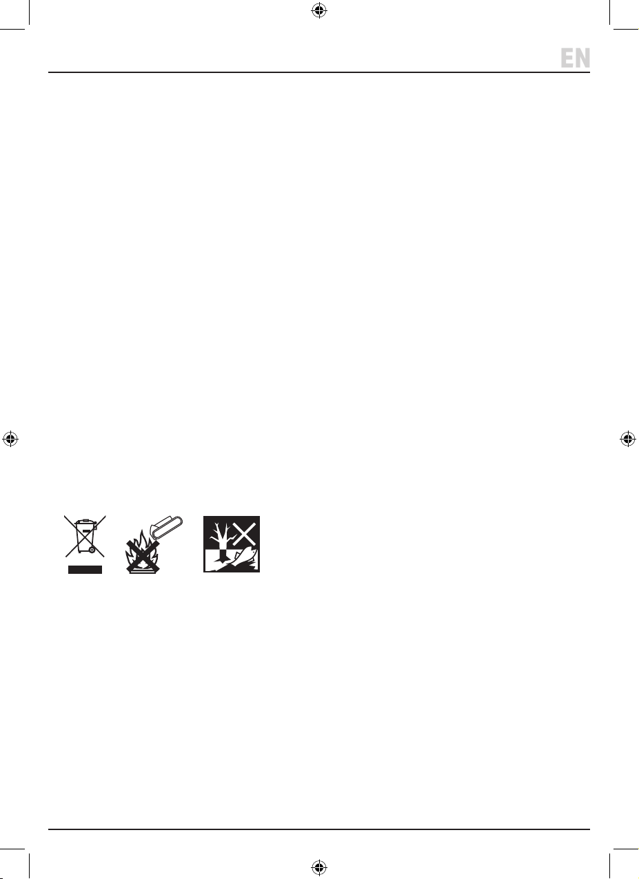
• DO NOT dispose of this product with domestic waste;
most local authorities provide appropriate recycling
facilities.
• DO NOT burn or mutilate batteries; this may release
toxic or corrosive substances.
• Dispose of lubricants separately and in accordance
with local regulations; DO NOT abandon it in the
environment.
– 21 –
Page 22
13. Explanation of Symbols
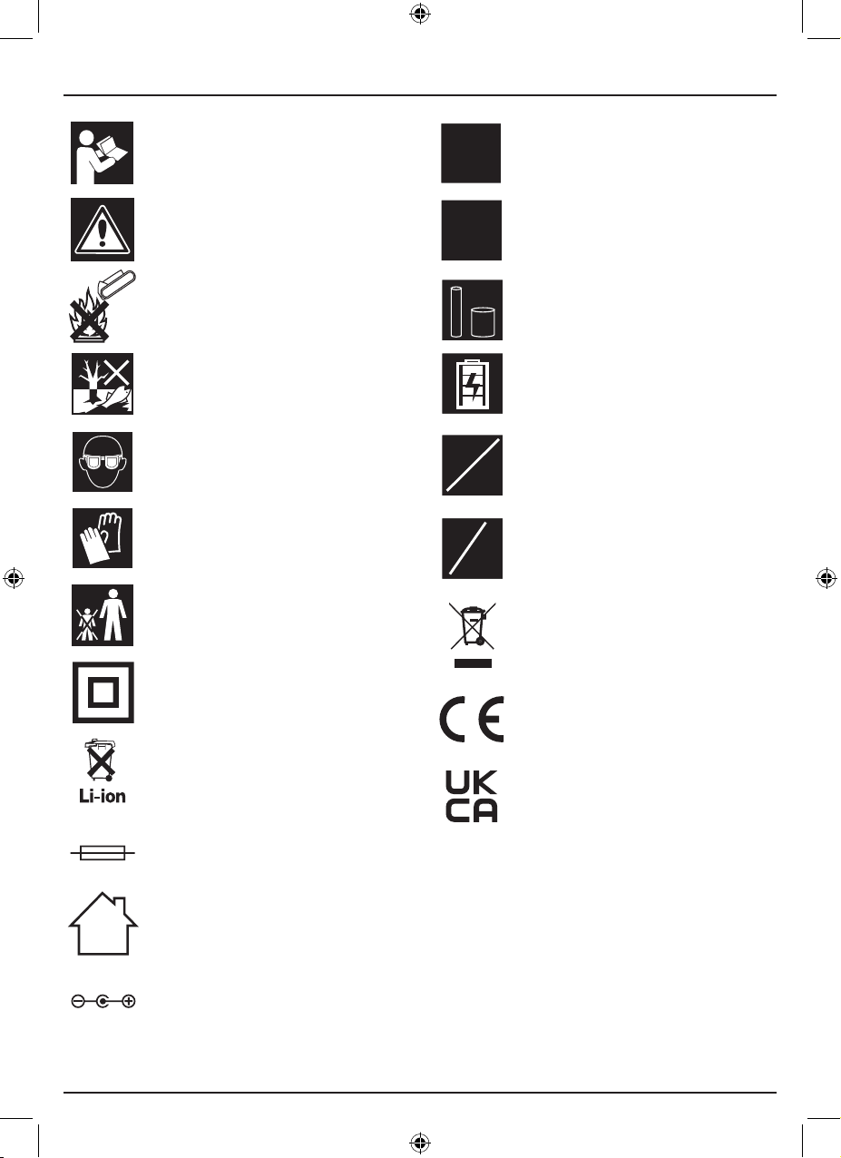
10,000
max
psi
100/
170gsm
450g
Bulk
400g
Lo
Hi
oz
g
Read the instruction manual
Warning!
Do not incinerate or throw onto re
Do not abandon in the environment
Wear suitable eye/face protection
Wear protective gloves
Keep out of the reach of children
Class II construction
(Double insulated)
Max. output pressure
Max. ow rates
Lubricant load capacities
Battery level indicator
High/low output mode
Output in g/oz
WEEE –
Waste Electrical & Electronic Equipment
Do not dispose of Waste Electrical & Electronic Equipment
in with domestic rubbish
European conformity
T3.15A
Lithium-ion product
UK Conformity Assessed
Fuse-protected device
For indoor use only;
do not expose to rain
Polarity indication
– 22 –
Page 23
Notes
EN
– 23 –
Page 24

Contact Details
Draper Tools
Draper Tools Limited
Hursley Road
Chandler’s Ford
Eastleigh
Hampshire
SO53 1YF
UK
Website: drapertools.com
Email: [email protected]
Product Helpline: +44 (0) 23 8049 4344
Telephone Sales Desk: +44 (0) 23 8049 4333
General Enquiries: +44 (0) 23 8026 6355
General Fax: +44 (0) 23 8026 0784
Please contact the Draper Tools Product Helpline for repair and servicing enquiries.
Delta International
Delta International BV
Oude Graaf 8
6002 NL
Weert
Netherlands
© Published by Draper Tools Limited
 Loading...