

Page 1
EHV/SAFETY
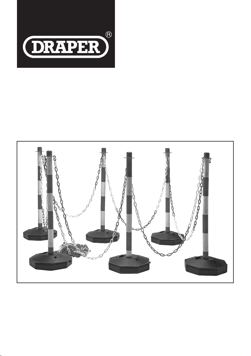
EXCLUSION
ZONE KIT
99464
These instructions accompanying the product are the original instructions. This document is part of the product, keep
it for the life of the product passing it on to any subsequent holder of the product. Read all these instructions before
assembling, operating or maintaining this product.
This manual has been compiled by Draper Tools describing the purpose for which the product has been designed,
and contains all the necessary information to ensure its correct and safe use. By following all the general safety
instructions contained in this manual, it will ensure both product and operator safety, together with longer life of the
product itself.
All photographs and drawings in this manual are supplied by Draper Tools to help illustrate the operation of the
product.
Whilst every effort has been made to ensure the accuracy of information contained in this manual, the Draper Tools
policy of continuous improvement determines the right to make modifications without prior warning.
Page 2
1. TITLE PAGE
1.1 INTRODUCTION:
USER MANUAL FOR:
EHV/Safety Exclusion Zone
Stock No: 99464
Part No: EZONE
1.2 REVISIONS:
Date first published January 2020.
As our user manuals are continually updated, users
should make sure that they use the very latest
version.
Downloads are available from: http://drapertools.
com/manuals
Draper Tools Limited, Hursley Road
Chandler’s Ford, Eastleigh, Hampshire
SO53 1YF. UK
Website: drapertools.com
Product Help Line: +44 (0) 23 8049 4344
General Fax: +44 (0) 23 8026 0784
A proof of purchase must be provided with the tool.
If upon inspection it is found that the fault occurring is
due to defective materials or workmanship, repairs
will be carried out free of charge. This warranty
period covering parts and labour is 12 months from
the date of purchase except where tools are hired out
when the warranty period is 90 days from the date of
purchase. This warranty does not apply to any
consumable parts, any type of battery or normal wear
and tear, nor does it cover any damage caused by
misuse, careless or unsafe handling, alterations,
accidents, or repairs attempted or made by any
personnel other than the authorised Draper warranty
repair agent.
Note: If the tool is found not to be within the terms of
warranty, repairs and carriage charges will be quoted
and made accordingly.
This warranty applies in lieu of any other warranty
expressed or implied and variations of its terms are
not authorised.
Your Draper warranty is not effective unless you can
produce upon request a dated receipt or invoice to
verify your proof of purchase within the warranty
period.
Please note that this warranty is an additional benefit
and does not affect your statutory rights.
Draper Tools Limited.
1.3 UNDERSTANDING THIS MANUALS
SAFETY CONTENT:
Warning! – Information that draws attention to the
risk of injury or death.
Important – Information that draws attention to the
risk of damage to the product or surroundings.
1.4 COPYRIGHT © NOTICE:
Copyright © Draper Tools Limited.
Permission is granted to reproduce this publication
for personal and educational use only. Commercial
copying, redistribution, hiring or lending is prohibited.
No part of this publication may be stored in a retrieval
system or transmitted in any other form or means
without written permission from Draper Tools Limited.
In all cases this copyright notice must remain intact.
2. WARRANTY
Draper tools have been carefully tested and
inspected before shipment and are guaranteed to be
free from defective materials and workmanship.
Should the tool develop a fault, please return the
complete tool to your nearest distributor or contact:
Draper Tools Limited, Chandler’s Ford, Eastleigh,
Hampshire, SO53 1YF. England.
Telephone Sales Desk: (023) 8049 4333 or
Product Help Line (023) 8049 4344.
3. TECHNICAL DESCRIPTION
(4)
(6)
(2)
(3)
(7)
(1)
– 2 –
(5)
Page 3
3. TECHNICAL DESCRIPTION
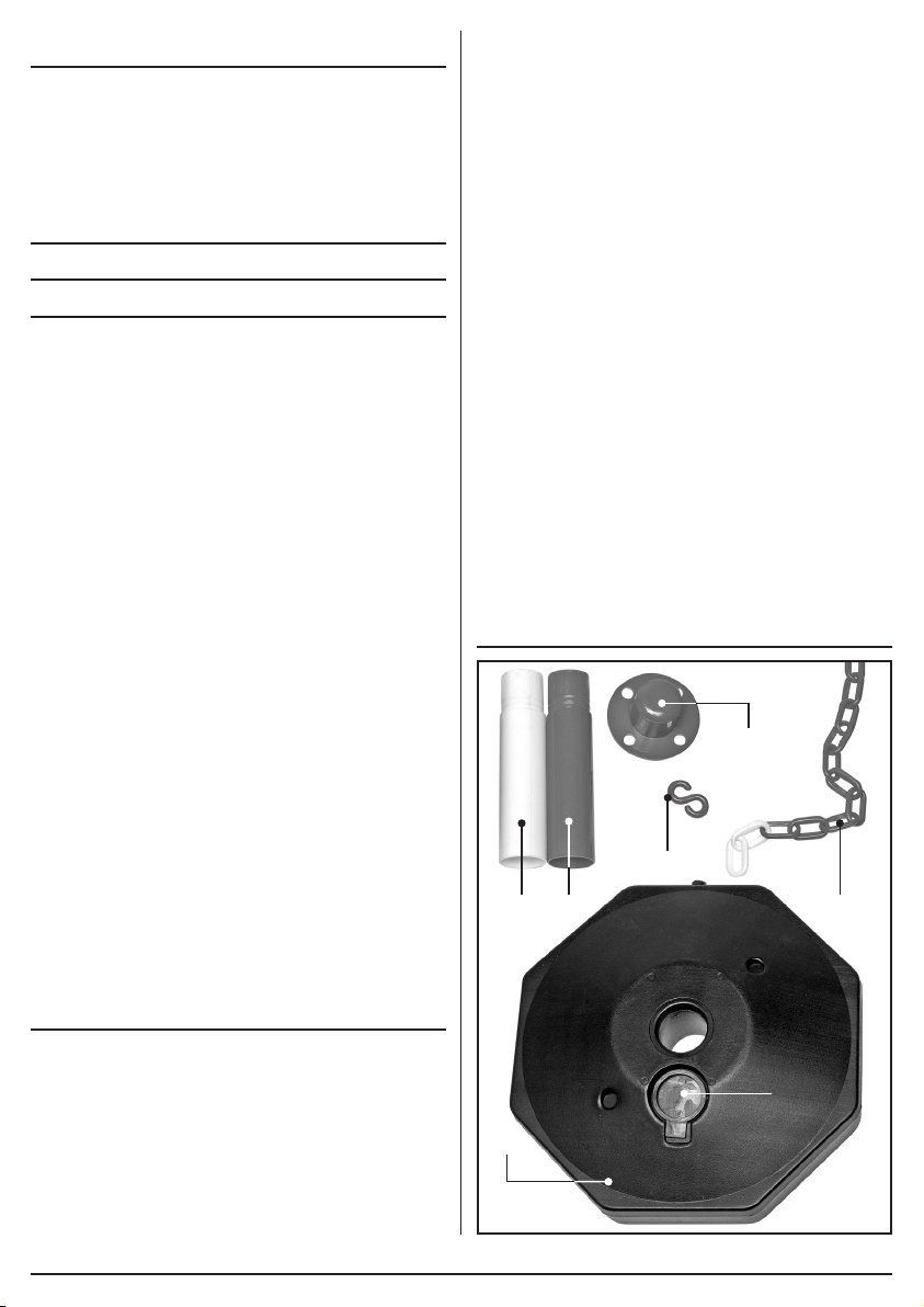
(1) 6 × Bases.
(2) 18 × Post sections (white).
(3) 18 × Post sections (red).
(4) 6 × Barrier chain connectors.
(5) 25M Red and white chain.
(6) 10 × ‘S’ Hooks.
(7) Base filling cap.
4. ASSEMBLY
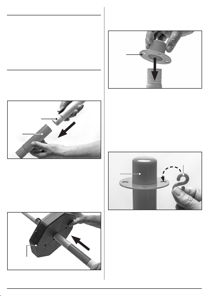
4.1 ASSEMBLING THE POSTS – FIG1.
The six posts are made up of six connecting sections
alternating in colour:
− Push fit the sections (2) and (3) together using
six sections of alternating red and white colours.
(2)
(3)
4.3 FITTING THE BARRIER CHAIN
CONNECTORS – FIG. 3.
Slide a barrier chain connector cap (4)onto the end
of each of the assembled six posts.
(4)
3 FIG.
4.4 FITTING THE ‘S’ HOOKS TO THE
BARRIER CHAIN CONNECTORS –
FIG. 4.
The ‘S’ hooks (6)are used to connect the barrier
chain to the posts.
− The hooks fit into any of the four holes located on
the barrier chain connector cap (4).
− The four holes enable the exclusion zone kit to
be set out in a variety of different sized areas and
positions depending on the user’s requirements.
1 FIG.
4.2 FITTING THE POSTS TO THE
BASES – FIG2.
Attach the posts to the base sections (1):
− Insert a completed post into the hole in the base
through the underside of the base. The post
can only be inserted into the base this way.
− Slide the post along its full extent as far along as
far as it will go until it locks into the base.
(1)
2 FIG.
(6)
(4)
4 FIG.
– 3 –
Page 4
4. ASSEMBLY
CONTACTS
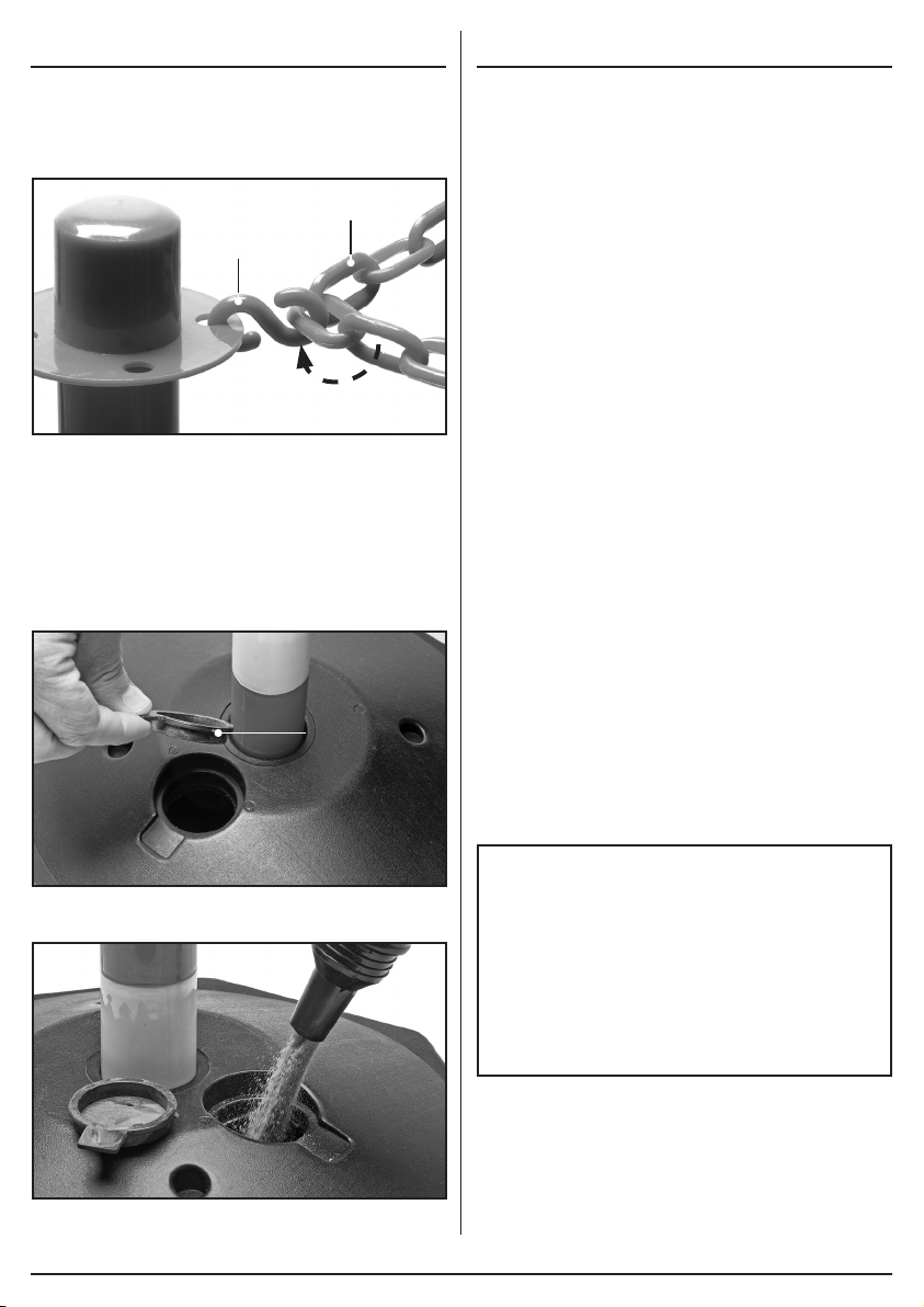
4.5 FITTING THE CHAIN – FIG. 5.
− Connect the barrier chain (5) to an ‘S’ hook (6)
by threading the free end of the hook through the
chain links.
(5)
(6)
5 FIG.
4.6 STABILISING THE BASES –
FIG. 6 – 7.
The base units need to be filled with either water or
sand to ensure adequate stability when in use.
− Remove the filling cap (7)and fill the base.
− Ensure the cap is replaced tightly when full.
Draper Tools Limited, Hursley Road,
Chandler’s Ford, Eastleigh, Hampshire.
SO53 1YF. U.K.
Website: drapertools.com
email: [email protected]
Product Help Line: +44 (0) 23 8049 4344
Sales Desk: +44 (0) 23 8049 4333
General Enquiries: +44 (0) 23 8026 6355
Service/Warranty Repair Agent:
For aftersales servicing or warranty repairs, please
contact the Draper Tools Help Line for details of an
agent in your local area.
(7)
YOUR DRAPER STOCKIST
6 FIG.
DBCH0120
©Published by Draper Tools Limited.
No part of this publication may be reproduced, stored
in a retrieval system or transmitted in any form or by
any means, electronic, mechanical photocopying,
7 FIG.
recording or otherwise without prior permission in
writing from Draper Tools Ltd.
– 4 –
 Loading...