

Page 1
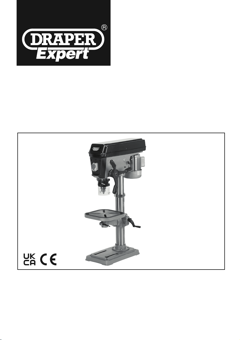
230V 16 SPEED
BENCH/FLOOR STANDING
DRILL
95314 / 95092
Stock No.95314 shown
These instructions accompanying the product are the original instructions. This document is part of the product,
keep it for the life of the product passing it on to any subsequent holder of the product. Read all these
instructions before assembling, operating or maintaining this product.
This manual has been compiled by Draper Tools describing the purpose for which the product has been
designed, and contains all the necessary information to ensure its correct and safe use. By following all the
general safety instructions contained in this manual, it will ensure both product and operator safety, together
with longer life of the product itself.
All photographs and drawings in this manual are supplied by Draper Tools to help illustrate the operation of the
product.
Whilst every effort has been made to ensure the accuracy of information contained in this manual, the Draper
Tools policy of continuous improvement determines the right to make modifications without prior warning.
Page 2

1. TITLE PAGE
2. CONTENTS
1. TITLE PAGE
1.1 INTRODUCTION..........................................................................................................2
1.2 REVISION HISTORY ..................................................................................................2
1.3 UNDERSTANDING THIS MANUAL ............................................................................. 2
1.4 COPYRIGHT NOTICE .................................................................................................2
2. CONTENTS
2.1 CONTENTS.................................................................................................................. 3
3. WARRANTY
3.1 WARRANTY.................................................................................................................4
4. INTRODUCTION
4.1 SCOPE......................................................................................................................... 5
4.2 SPECIFICATION ..........................................................................................................5
4.3 HANDLING AND STORAGE........................................................................................ 5
5. HEALTH AND SAFETY INFORMATION
5.1 GENERAL SAFETY INSTRUCTIONS FOR POWER TOOL USE ............................6-7
5.2 ADDITIONAL SAFETY INSTRUCTIONS FOR DRILLS............................................... 8
5.3 CONNECTION TO THE POWER SUPPLY ................................................................. 9
6. TECHNICAL DESCRIPTION
6.1 IDENTIFICATION .......................................................................................................10
7. UNPACKING AND CHECKING
7.1 PACKAGING .............................................................................................................. 11
7.2 WHAT’S IN THE BOX?............................................................................................... 11
8. PREPARING THE DRILL
8.1 BASE TO COLUMN ...................................................................................................12
8.2 TABLE BRACKET .....................................................................................................12
8.3 TABLE ........................................................................................................................13
8.4 HEADSTOCK ............................................................................................................. 13
8.5 PLUNGE HANDLES................................................................................................... 13
8.6 CHUCK AND ARBOR.................................................................................................14
8.7 CHUCK GUARD......................................................................................................... 14
8.8 BENCH/FLOOR MOUNTING.....................................................................................14
9. SETTING THE DRILL
9.1 SPINDLE SPEED ADJUSTMENT.............................................................................. 15
9.2 BRILL BIT INSTALLATION/REPLACEMENT.............................................................16
9.3 NO-VOLT SWITCH.....................................................................................................16
9.4 WORK TABLE ADJUSTMENT................................................................................... 17
9.5 GENERAL DRILLING................................................................................................. 18
9.6 DUST AND SWARF................................................................................................... 18
10. TROUBLESHOOTING
10.1 TROUBLESHOOTING ............................................................................................... 19
11. MAINTENANCE
11.1 MAINTENANCE .........................................................................................................20
11.2 ARBOR REMOVAL .................................................................................................... 20
12. OPTIONAL ACCESSORIES
12.1 OPTIONAL ACCESSORIES....................................................................................... 21
13. EXPLANATION OF SYMBOLS
13.1 EXPLANATION OF SYMBOLS.................................................................................. 22
14. DISPOSAL
14.1 DISPOSAL..................................................................................................................23
DECLARATION OF CONFORMITY..............................................................................ENCLOSED
- 3 -
1.1 INTRODUCTION:
USER MANUAL FOR: 230V 16 Speed Bench/Floor Standing Drill
Stock No’s: 95314 & 95092
Part No’s: BD650/16E & DP650/16E
1.2 REVISIONS:
Date first published November 2018.
Date first revised: April 2022.
As our user manuals are continually updated, users should make sure that they use
the very latest version.
Downloads are available from: http://drapertools.com/manuals
Draper Tools Limited Draper Tools Limited
Hursley Road Oude Graaf 8
Chandler’s Ford 6002 NL
Eastleigh WEERT
Hampshire Netherlands
SO53 1YF
UK
Website: drapertools.com
Product Helpline: +44 (0) 23 8049 4344
General Fax: +44 (0) 23 8026 0784
1.3 UNDERSTANDING THIS MANUALS SAFETY CONTENT:
WARNING! – Information that draws attention to the risk of injury or death.
CAUTION! – Information that draws attention to the risk of damage to the product or
surroundings.
1.4 COPYRIGHT © NOTICE:
Copyright © Draper Tools Limited.
Permission is granted to reproduce this publication for personal and educational use
only. Commercial copying, redistribution, hiring or lending is prohibited.
No part of this publication may be stored in a retrieval system or transmitted in any
other form or means without written permission from Draper Tools Limited.
In all cases this copyright notice must remain intact.
Page 3

2. CONTENTS
1. TITLE PAGE
1.1 INTRODUCTION..........................................................................................................2
1.2 REVISION HISTORY ..................................................................................................2
1.3 UNDERSTANDING THIS MANUAL ............................................................................. 2
1.4 COPYRIGHT NOTICE .................................................................................................2
2. CONTENTS
2.1 CONTENTS.................................................................................................................. 3
3. WARRANTY
3.1 WARRANTY.................................................................................................................4
4. INTRODUCTION
4.1 SCOPE......................................................................................................................... 5
4.2 SPECIFICATION ..........................................................................................................5
4.3 HANDLING AND STORAGE........................................................................................ 5
5. HEALTH AND SAFETY INFORMATION
5.1 GENERAL SAFETY INSTRUCTIONS FOR POWER TOOL USE ............................6-7
5.2 ADDITIONAL SAFETY INSTRUCTIONS FOR DRILLS............................................... 8
5.3 CONNECTION TO THE POWER SUPPLY ................................................................. 9
6. TECHNICAL DESCRIPTION
6.1 IDENTIFICATION .......................................................................................................10
7. UNPACKING AND CHECKING
7.1 PACKAGING .............................................................................................................. 11
7.2 WHAT’S IN THE BOX?............................................................................................... 11
8. PREPARING THE DRILL
8.1 BASE TO COLUMN ...................................................................................................12
8.2 TABLE BRACKET .....................................................................................................12
8.3 TABLE ........................................................................................................................13
8.4 HEADSTOCK ............................................................................................................. 13
8.5 PLUNGE HANDLES................................................................................................... 13
8.6 CHUCK AND ARBOR.................................................................................................14
8.7 CHUCK GUARD......................................................................................................... 14
8.8 BENCH/FLOOR MOUNTING.....................................................................................14
9. SETTING THE DRILL
9.1 SPINDLE SPEED ADJUSTMENT.............................................................................. 15
9.2 BRILL BIT INSTALLATION/REPLACEMENT.............................................................16
9.3 NO-VOLT SWITCH.....................................................................................................16
9.4 WORK TABLE ADJUSTMENT................................................................................... 17
9.5 GENERAL DRILLING................................................................................................. 18
9.6 DUST AND SWARF................................................................................................... 18
10. TROUBLESHOOTING
10.1 TROUBLESHOOTING ............................................................................................... 19
11. MAINTENANCE
11.1 MAINTENANCE .........................................................................................................20
11.2 ARBOR REMOVAL .................................................................................................... 20
12. OPTIONAL ACCESSORIES
12.1 OPTIONAL ACCESSORIES....................................................................................... 21
13. EXPLANATION OF SYMBOLS
13.1 EXPLANATION OF SYMBOLS.................................................................................. 22
14. DISPOSAL
14.1 DISPOSAL..................................................................................................................23
DECLARATION OF CONFORMITY..............................................................................ENCLOSED
- 3 -
Page 4

4. INTRODUCTION
4.1 SCOPE
This product is intended for trade use and has the quality and features to meet and exceed the
expectations of the most demanding user. Any application other than that it was intended for, is
considered misuse.
Designed to drill into wood, plastics, ceramics, and many metals (drill bits sold separately).
4.2 SPECIFICATION
Stock No. ........................................................... 95314......................................................... 95092
Part No. ......................................................... BD650/16E ............................................ DP650/16E
Rated voltage .................................................... 230V ........................................................... 230V
Rated frequency ................................................ 50Hz ........................................................... 50Hz
Rated input ........................................................650W .......................................................... 650W
Speed settings ......................................................16 ................................................................. 16
Revolutions per minute (no load) .............. 120-3,000min-1...................................120-3,000min
-1
Chuck capacity ................................................3-16mm .................................................... 3-16mm
Drilling capacity ..................................................19mm ........................................................ 19mm
Spindle taper .......................................................MT2 ............................................................. MT2
Spindle travel .....................................................80mm ........................................................ 80mm
Throat ................................................................178mm ..................................................... 178mm
Column Ø ...........................................................80mm ........................................................ 80mm
Collar Ø .............................................................60mm ........................................................ 60mm
Chuck to table ..................................................323mm ..................................................... 648mm
Chuck to base ...................................................515mm ................................................... 1171mm
Table tilt ...............................................................±45° ............................................................. ±45°
Head rotation ....................................................... 360° ............................................................. 360°
Table rotation .......................................................360° ............................................................. 360°
Table dimensions ..........................................290x290mm .......................................... 290x290mm
Base dimensions ...........................................460x275mm .......................................... 460x275mm
Height ...............................................................1000mm .................................................. 1650mm
Sound power level............................................. 85db(A) .................................................... 85db(A)
Sound pressure level ........................................ 70db(A) .................................................... 70db(A)
Vibration level ................................................. <2.5m/s2 ................................................. <2.5m/s
2
Weight ...............................................................71kgs ......................................................... 78kgs
4.3 HANDLING & STORAGE
– Care must be taken when handling this product.
● Dropping this power tool could have an effect on its accuracy and could also result in personal
injury. This product is not a toy and must be respected.
– Environmental conditions can have a detrimental effect on this product if neglected.
● Exposure to damp air can gradually corrode components.
● If the product is unprotected from dust and debris, components will become clogged.
● If not cleaned and maintained correctly or regularly, the machine will not perform at its best.
* Continuous A-Weighted Sound Pressure Level at the workstation in accordance to prEN ISO 15744:1999
and declared according to EN ISO 4871.
** A-Weighted Sound Power Level in accordance to prEN ISO 15744:1999 and declared according to EN ISO 4871.
- 5 -
3. WARRANTY
3.1 WARRANTY
Draper tools have been carefully tested and inspected before shipment and are guaranteed to be
free from defective materials and workmanship.
Should the tool develop a fault, please return the complete tool to your nearest distributor or
contact:
Draper Tools Limited, Chandler's Ford, Eastleigh, Hampshire, SO53 1YF. England.
Telephone Sales Desk: (023) 8049 4333 or:
Product Helpline (023) 8049 4344.
A proof of purchase must be provided.
If upon inspection it is found that the fault occurring is due to defective materials or workmanship,
repairs will be carried out free of charge. This warranty period covering labour is 12 months from
the date of purchase except where tools are hired out when the warranty period is 90 days from
the date of purchase. The warranty is extended to 24 months for parts only. This warranty does
not apply to any consumable parts, any type of battery or normal wear and tear, nor does it cover
any damage caused by misuse, careless or unsafe handling, alterations, accidents, or repairs
attempted or made by any personnel other than the authorised Draper warranty repair agent.
Note: If the tool is found not to be within the terms of warranty, repairs and carriage charges will
be quoted and made accordingly.
This warranty applies in lieu of any other warranty expressed or implied and variations of its
terms are not authorised.
Your Draper warranty is not effective unless you can produce upon request a dated receipt or
invoice to verify your proof of purchase within the warranty period.
Please note that this warranty is an additional benefit and does not affect your statutory rights.
Draper Tools Limited.
- 4 -
Page 5

4. INTRODUCTION
4.1 SCOPE
This product is intended for trade use and has the quality and features to meet and exceed the
expectations of the most demanding user. Any application other than that it was intended for, is
considered misuse.
Designed to drill into wood, plastics, ceramics, and many metals (drill bits sold separately).
4.2 SPECIFICATION
Stock No. ........................................................... 95314......................................................... 95092
Part No. ......................................................... BD650/16E ............................................ DP650/16E
Rated voltage .................................................... 230V ........................................................... 230V
Rated frequency ................................................ 50Hz ........................................................... 50Hz
Rated input ........................................................650W .......................................................... 650W
Speed settings ......................................................16 ................................................................. 16
Revolutions per minute (no load) .............. 120-3,000min-1...................................120-3,000min
Chuck capacity ................................................3-16mm .................................................... 3-16mm
Drilling capacity ..................................................19mm ........................................................ 19mm
Spindle taper .......................................................MT2 ............................................................. MT2
Spindle travel .....................................................80mm ........................................................ 80mm
Throat ................................................................178mm ..................................................... 178mm
Column Ø ...........................................................80mm ........................................................ 80mm
Collar Ø .............................................................60mm ........................................................ 60mm
Chuck to table ..................................................323mm ..................................................... 648mm
Chuck to base ...................................................515mm ................................................... 1171mm
Table tilt ...............................................................±45° ............................................................. ±45°
Head rotation ....................................................... 360° ............................................................. 360°
Table rotation .......................................................360° ............................................................. 360°
Table dimensions ..........................................290x290mm .......................................... 290x290mm
Base dimensions ...........................................460x275mm .......................................... 460x275mm
Height ...............................................................1000mm .................................................. 1650mm
Sound power level............................................. 85db(A) .................................................... 85db(A)
Sound pressure level ........................................ 70db(A) .................................................... 70db(A)
Vibration level ................................................. <2.5m/s2 ................................................. <2.5m/s
Weight ...............................................................71kgs ......................................................... 78kgs
4.3 HANDLING & STORAGE
– Care must be taken when handling this product.
● Dropping this power tool could have an effect on its accuracy and could also result in personal
injury. This product is not a toy and must be respected.
– Environmental conditions can have a detrimental effect on this product if neglected.
● Exposure to damp air can gradually corrode components.
● If the product is unprotected from dust and debris, components will become clogged.
● If not cleaned and maintained correctly or regularly, the machine will not perform at its best.
* Continuous A-Weighted Sound Pressure Level at the workstation in accordance to prEN ISO 15744:1999
and declared according to EN ISO 4871.
** A-Weighted Sound Power Level in accordance to prEN ISO 15744:1999 and declared according to EN ISO 4871.
-1
2
- 5 -
Page 6

5. HEALTH AND SAFETY INFORMATION
5. HEALTH AND SAFETY INFORMATION
- 7 -
Wait for the machine to stop. Unless the machine is fitted with a safety brake, some parts may
continue to move due to momentum. Wait for all parts to stop, then unplug it from the power supply
before making any adjustments, carrying out maintenance operations or just finishing using the tool.
Remove and check setting tools. Some machinery requires the use of additional tools or keys to
set, load or adjust the power tool. Before starting the power tool always check to make certain they
have been removed and are safely away from the machine.
Prevent unintentional starting. Before plugging any machine in to the power supply, make sure the
switch is in the OFF position. If the machine is portable, do not hold the machine near the switch and
take care when putting the machine down, that nothing can operate the switch.
Carefully select an extension lead. Some machines are not suitable for use with extension leads. If
the tool is designed for use outdoors, use an extension lead also suitable for that environment. When
using an extended lead, select one capable of handling the current (amps) drawn by the machine in
use. Fully extend the lead regardless of the distance between the power supply and the tool. Excess
current (amps) and a coiled extension lead will both cause the cable to heat up and can result in fire.
Concentrate and stay alert. Distractions are likely to cause an accident. Never operate a power tool
if you are under the influence of drugs (prescription or otherwise), including alcohol or if you are
feeling tired. Being disorientated will result in an accident.
Have this tool repaired by a qualified person. This tool is designed to conform to the relevant
international and local standards and as such should be maintained and repaired by someone
qualified, using only original parts supplied by the manufacturer. This will ensure the tool remains safe
to use.
When using any type of power tool there are steps that should be taken to make sure that you, as
the user, remain safe.
Common sense and a respect for the tool will help reduce the risk of injury.
5.1 GENERAL SAFETY INSTRUCTIONS FOR POWER TOOL USE
Warning!
● Read all safety warnings and all instructions. Failure to follow the warnings and instructions
may result in electric shock, fire and/or serious injury.
● The term "power tool" in the warnings refers to your mains operated (corded) power tool or
battery-operated (cordless) power tool.
Most important: You must know how to safely start and stop this machine, especially in an
emergency.
Keep the work area tidy and clean. Attempting to clear clutter from around the machine during use
will reduce your concentration. Mess on the floor creates a trip hazard. Any liquid spilled on the floor
could result in you slipping.
Find a suitable location. If the machine is bench mounted, the location should provide good natural
light or artificial lighting as a replacement. Avoid damp and dusty locations as it will have a negative
effect on the machine’s performance. If the machine is portable do not expose the tool to rain. In all
cases do not operate power tools near any flammable materials.
Keep bystanders away. Children, onlookers and passers by must be restricted from entering the
work area for their own protection. The barrier must extend a suitable distance from the tool user.
Unplug and house all power tools that are not in use. A power tool should never be left unattended
while connected to the power supply. They must be housed in a suitable location, away locked up
and from children.
Do not overload or misuse the tool. All tools are designed for a purpose and are limited to what
they are capable of doing. Do not attempt to use a power tool (or adapt it in any way) for an
application it is not designed for. Select a tool appropriate for the size of the job. Overloading a tool
will result in tool failure and user injury. This covers the use of accessories.
Dress properly. Loose clothing, long hair and jewellery are all dangerous because they can become
entangled in moving machinery. This can also result in parts of body being pulled into the machine.
Clothing should be close fitted, with any long hair tired back and jewellery and neck ties removed.
Footwear must be fully enclosed and have a non-slip sole.
Wear personal protective equipment (PPE). Dust, noise, vibration and swarf can all be dangerous
if not suitably protected against. If the work involving the power tool creates dust or fumes wear a
dust mask. Vibration to the hand, caused by operating some tools for longer periods must be
protected against. Wear vibration reducing gloves and allow long breaks between uses. Protect
against dust and swarf by wearing approved safety goggles or a face shield. These are some of the
more common hazards and preventions, however, always find out what hazards are associated with
the machine/work process and wear the most suitable protective equipment available.
Do not breathe contaminated air. If the work creates dust or fumes connect the machine (if
possible) to an extraction system either locally or remotely. Working outdoors can also help if
possible.
Move the machine as instructed. If the machine is hand held, do not carry it by the power supply
cable. If the product is heavy, employ a second or third person to help move it safely or use a
mechanical device. Always refer to the instructions for the correct method.
Do not overreach. Extending your body too far can result in a loss of balance and you falling. This
could be from a height or onto a machine and will result in injury.
Maintain your tools correctly. A well maintained tool will do the job safely. Replace any damaged
or missing parts immediately with original parts from the manufacturer. As applicable keep blades
sharp, moving parts clean, oiled or greased, handles clean and emergency devices working.
- 6 -
Page 7

5. HEALTH AND SAFETY INFORMATION
Wait for the machine to stop. Unless the machine is fitted with a safety brake, some parts may
continue to move due to momentum. Wait for all parts to stop, then unplug it from the power supply
before making any adjustments, carrying out maintenance operations or just finishing using the tool.
Remove and check setting tools. Some machinery requires the use of additional tools or keys to
set, load or adjust the power tool. Before starting the power tool always check to make certain they
have been removed and are safely away from the machine.
Prevent unintentional starting. Before plugging any machine in to the power supply, make sure the
switch is in the OFF position. If the machine is portable, do not hold the machine near the switch and
take care when putting the machine down, that nothing can operate the switch.
Carefully select an extension lead. Some machines are not suitable for use with extension leads. If
the tool is designed for use outdoors, use an extension lead also suitable for that environment. When
using an extended lead, select one capable of handling the current (amps) drawn by the machine in
use. Fully extend the lead regardless of the distance between the power supply and the tool. Excess
current (amps) and a coiled extension lead will both cause the cable to heat up and can result in fire.
Concentrate and stay alert. Distractions are likely to cause an accident. Never operate a power tool
if you are under the influence of drugs (prescription or otherwise), including alcohol or if you are
feeling tired. Being disorientated will result in an accident.
Have this tool repaired by a qualified person. This tool is designed to conform to the relevant
international and local standards and as such should be maintained and repaired by someone
qualified, using only original parts supplied by the manufacturer. This will ensure the tool remains safe
to use.
- 7 -
Page 8

5. HEALTH AND SAFETY INFORMATION
5. HEALTH AND SAFETY INFORMATION
- 9 -
5.3 CONNECTION TO THE POWER SUPPLY
Caution: Risk of electric shock. Do not open.
This appliance is supplied with a moulded 3 pin mains plug for your safety. The value of the fuse
fitted is marked on the pin face of the plug. Should the fuse need replacing, ensure the substitute
is of the correct rating, approved to BS1362 and ASTA or BSI Kite marked.
ASTA
BSI
The fuse cover is removable with a small plain slot screwdriver. Ensure the fuse cover is replaced
before attempting to connect the plug to an electrical outlet. If the cover is missing, a replacement
must be obtained or the plug replaced with a suitable type.
If a replacement plug is to be fitted this must be carried out by a qualified electrician.
The damaged or incomplete plug, when cut from the cable should be disabled to prevent
connection to a live electrical outlet.
This appliance is Class I
†
and is designed for connection to a power supply matching that detailed
on the rating label and compatible with the plug fitted.
If an extension lead is required, use an approved and compatible lead rated for this appliance. If
using an extension lead, follow the instructions that came with your lead regarding maximum load
while cable is wound, if in doubt ensure the entire cable is unwound. Using a coiled extension lead
will generate heat which could melt the lead and cause a fire.
†
Earthed : This product requires an earth connection to protect against electric shock from
accessible conductive parts in the event of failure of the basic insulation.
IMPORTANT
If using an extension lead, follow the instructions that came with your lead regarding
maximum load while cable is wound. If in doubt, ensure that the entire cable is unwound.
Using a coiled extension lead will generate heat which could melt the lead and cause a fire.
5.2 ADDITIONAL SAFETY INSTRUCTIONS FOR DRILLS
MECHANICAL HAZARDS:
1. Crushing. When setting/changing a tool or maintaining the machine avoid crushing injuries
sustained between fixed and moving elements of the machine.
2. Cutting or Severing. At all times the workpiece shall be clamped as manual support will lead
to injury.
3. Entanglement. Switch off the machine for maintenance, workpiece loading/unloading, swarf/chip
removal, cutting/lubrication fluid application as contact with rotating spindle or tool will cause
entanglement and possibly lead to injury and entrapment.
4. Impact. Ensure the workpiece is securely clamped at all times to avoid sudden movement
(rotation) or ejection causing injury. Ensure any special tools associated with tool exchange, i.e.
chuck key are removed prior to attempting to start the machine.
5. Stabbing, Cutting or Puncture Wounds. Take care when handling the tools and avoid contact
with swarf and burrs created during drilling as they are extremely sharp.
ELECTRICAL HAZARDS:
1. Contact with Live parts. During commissioning, maintenance and trouble shooting operations
do not remove, open or expose any electrical, terminal and control boxes due to the danger of
electrocution. If the main cable is damaged, unplug the machine immediately and have the cable
replaced before continuing.
AUDIBLE HAZARDS:
1. Hearing Loss. Wear ear defenders during operation to avoid damage to hearing, however ensure
this does not interfere with speech communications or audible warnings.
MATERIAL HAZARDS:
1. Contact and Inhalation. Wear personal protective equipment to avoid contact from harmful
fluids, gases or dust thrown or created during the drilling process.
2. Fire or Explosion. Do not drill or drill in the vicinity of flammable or combustible materials.
LOCATION:
1. Posture. Ensure when mounting the machine that the chosen location does not lead to unhealthy
posture or repetitive strain during normal operation.
2. Lighting. Adequate lighting must be provided to ensure no operations are light impaired possibly
leading to injury.
3. Reach. Do not reach over or around the machine at any time.
UNEXPECTED START-UP:
1. Remove the plug. Remove the plug from the socket before carrying out adjustment, servicing
or maintenance.
ERRORS OF FITTING:
1. Tools. Ensure a suitable tool for the job in hand is securely and correctly fitted prior to starting the
machine. Guards shall be fitted and in place at all times.
STABILITY:
1. Toppling. The drill shall be securely bolted down to a suitable and level surface to prevent the
machine from overturning leading to injury.
2. Slipping. Ensure the area is clean of any residue cutting/lubrication fluid and other materials
which may lead to a slip, trip or other such hazard.
- 8 -
Page 9

5. HEALTH AND SAFETY INFORMATION
5.3 CONNECTION TO THE POWER SUPPLY
Caution: Risk of electric shock. Do not open.
This appliance is supplied with a moulded 3 pin mains plug for your safety. The value of the fuse
fitted is marked on the pin face of the plug. Should the fuse need replacing, ensure the substitute
is of the correct rating, approved to BS1362 and ASTA or BSI Kite marked.
ASTA
BSI
The fuse cover is removable with a small plain slot screwdriver. Ensure the fuse cover is replaced
before attempting to connect the plug to an electrical outlet. If the cover is missing, a replacement
must be obtained or the plug replaced with a suitable type.
If a replacement plug is to be fitted this must be carried out by a qualified electrician.
The damaged or incomplete plug, when cut from the cable should be disabled to prevent
connection to a live electrical outlet.
This appliance is Class I
on the rating label and compatible with the plug fitted.
If an extension lead is required, use an approved and compatible lead rated for this appliance. If
using an extension lead, follow the instructions that came with your lead regarding maximum load
while cable is wound, if in doubt ensure the entire cable is unwound. Using a coiled extension lead
will generate heat which could melt the lead and cause a fire.
†
Earthed : This product requires an earth connection to protect against electric shock from
accessible conductive parts in the event of failure of the basic insulation.
IMPORTANT
If using an extension lead, follow the instructions that came with your lead regarding
maximum load while cable is wound. If in doubt, ensure that the entire cable is unwound.
Using a coiled extension lead will generate heat which could melt the lead and cause a fire.
†
and is designed for connection to a power supply matching that detailed
- 9 -
Page 10
6. TECHNICAL DESCRIPTION
7.1 PACKAGING
Carefully remove the product from the packaging and examine it for any sign of damage that may have
happened during shipping. If any part is damaged or missing, please contact the Draper Help Line (the
telephone number appears on the Title page) and do not attempt to use the product.
The packaging material should be retained at least during the guarantee period in case the machine
needs to be returned for repair.
Warning!
● Some of the packaging materials used may be harmful to children. Do not leave any of these
materials in the reach of children.
● If any of the packaging is to be thrown away, make sure they are disposed of correctly,
according to local regulations.
7.2 WHAT´S IN THE BOX?
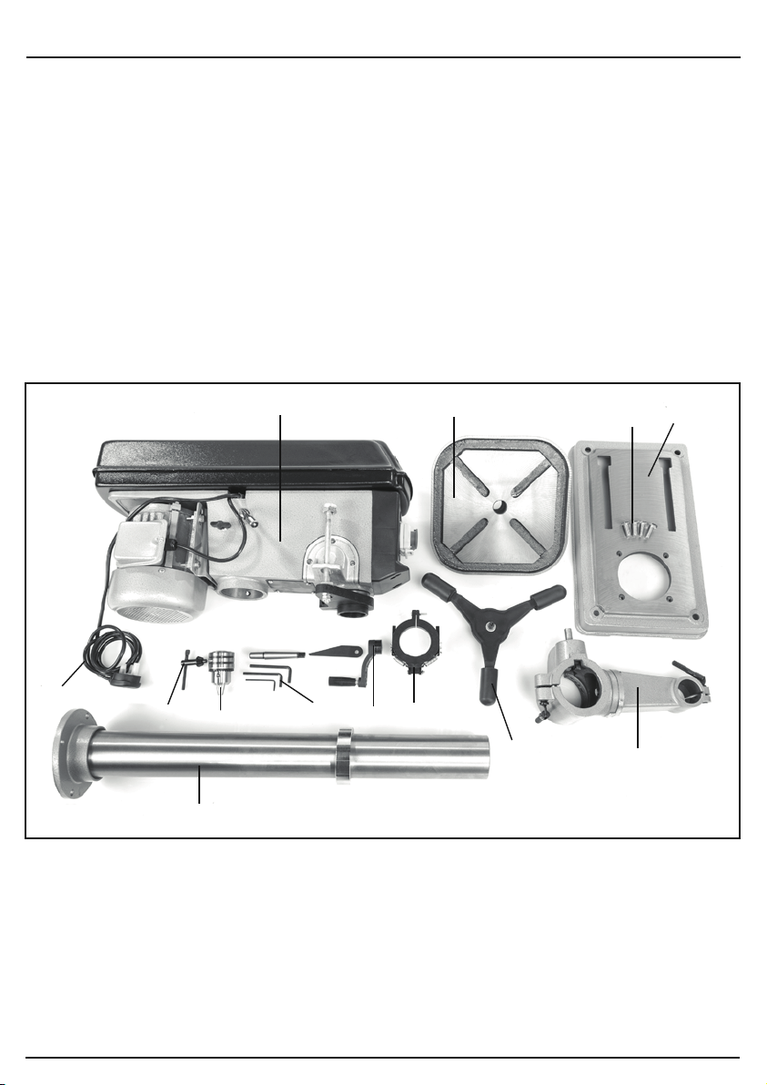
The packaging contains several parts and semi-assembled elements that require final assembly.
Lay out the contents and check off the items against those featured below.
7. UNPACKING AND CHECKING
(10) Geared chuck.
(11) Work table.
(14) Column.
(15) Base.
(16) Chuck key.
(18) Moulded plug & cable.
(23) Table height
crank handle.
(25) Hexagon keys.
(26) Bolts and washers.
(27) Plunger handles.
(28) Body.
(29) Guard assembly.
(30) Work table bracket.
- 11 -
(14)
(18)
(28)
(11)
(23)
(26)
(27)
(25)
(16)
(10)
(29)
(30)
(15)
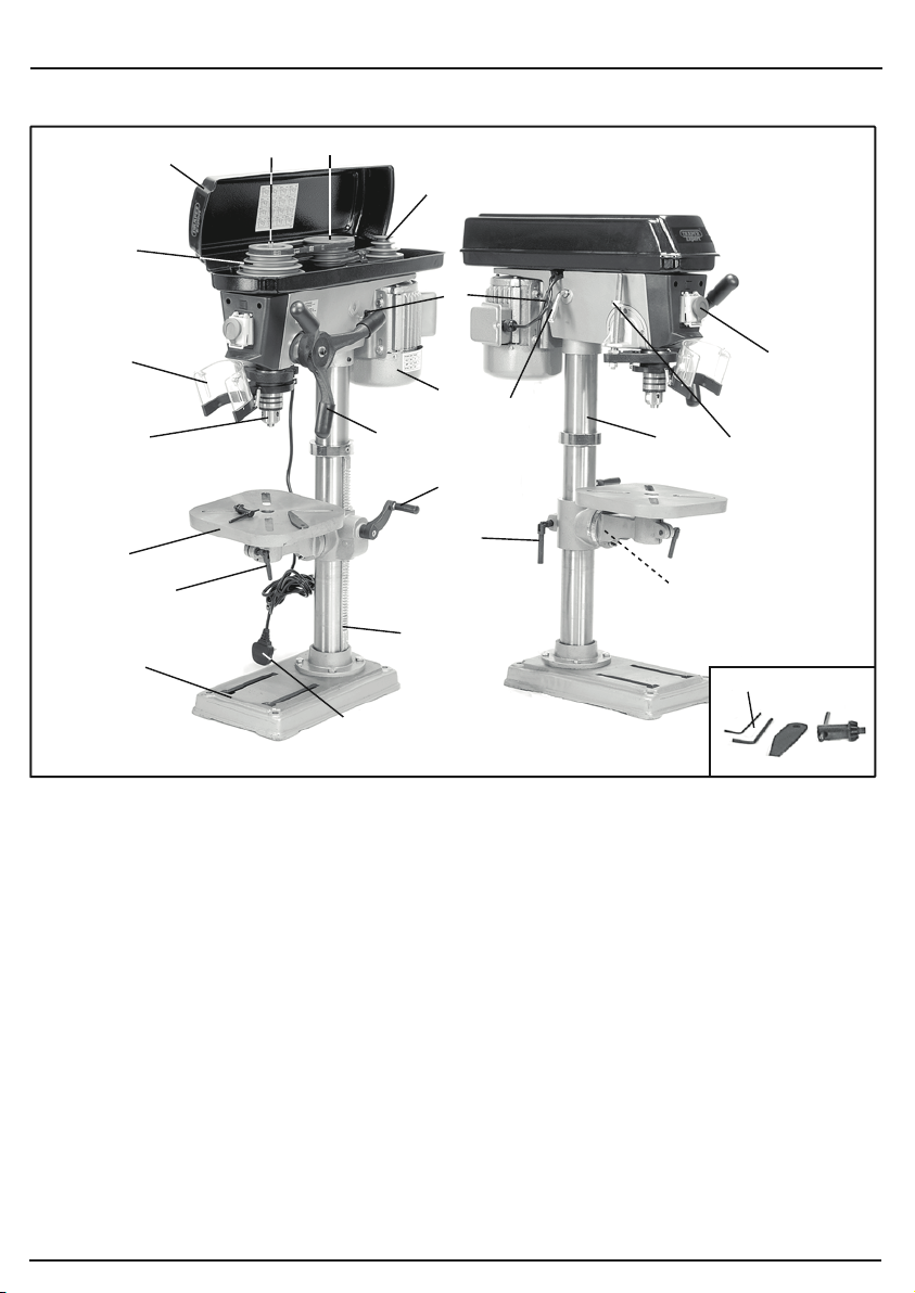
6.1 IDENTIFICATION
(6)
(8)
(2)
(10)
(11)
(24)
(15)
(21)
(5)
(9)
(13)
(4)
(7)
(1)
(23)
(12)
(3)
(14)
(17)
(20)
(25)
(18)
(1) Motor.
(2) Pulley cover.
(3) Motor tension lever.
(4) Motor pulley.
(5) Intermediate pulley.
(6) Spindle pulley.
(7) Motor tension locking knob.
(8) Guard.
(9) Plunge handle assembly.
(10) Geared chuck.
(11) Work table.
(12) Work table height/rotation
locking handle.
(13) Rack.
(14) Column.
(15) Base.
(16) Chuck key.
(17) Work table tilt locking bolt.
(18) BS moulded plug & cable.
(19) No-volt on/off switch.
(20) Depth stop.
(21) Spindle.
(22) Drift key.
(23) Table height crank handle.
(24) Table locking handle.
(25) Hex. keys.
- 10 -
Page 11
7. UNPACKING AND CHECKING
7.1 PACKAGING
Carefully remove the product from the packaging and examine it for any sign of damage that may have
happened during shipping. If any part is damaged or missing, please contact the Draper Help Line (the
telephone number appears on the Title page) and do not attempt to use the product.
The packaging material should be retained at least during the guarantee period in case the machine
needs to be returned for repair.
Warning!
● Some of the packaging materials used may be harmful to children. Do not leave any of these
● If any of the packaging is to be thrown away, make sure they are disposed of correctly,
7.2 WHAT´S IN THE BOX?
The packaging contains several parts and semi-assembled elements that require final assembly.
Lay out the contents and check off the items against those featured below.
materials in the reach of children.
according to local regulations.
(18)
(16)
(10) Geared chuck.
(11) Work table.
(14) Column.
(15) Base.
(16) Chuck key.
(14)
(10)
(28)
(25)
(23)
(18) Moulded plug & cable.
(23) Table height
crank handle.
(25) Hexagon keys.
(26) Bolts and washers.
(11)
(29)
(26)
(27)
(27) Plunger handles.
(28) Body.
(29) Guard assembly.
(30) Work table bracket.
(30)
(15)
- 11 -
Page 12
8. PREPARING THE DRILL
8. PREPARING THE DRILL
- 13 -
Slide the column ring (H) over the column and
locate the bevel on the top edge of the rack into
the bevelled rim of the ring. Tighten grub screw
(I) to secure.
NOTE: Adjust the table arm height to suit and
position centrally over the base before securing
the locking handle.
8.5 PLUNGE HANDLES - FIG. 8
Locate the plunge handle assembly (M) onto
the hub ensuring locating pin (N) is in position.
Secure with the hex. socket head bolt and
washer (O).
8.3 TABLE - FIG. 6
Slot the table into the table bracket and tighten
locking handle (J).
8.4 HEADSTOCK - FIG. 7
WARNING: The headstock assembly poses a
significant health and safety hazard while being
lifted and positioned into place. Seek assistance.
Lift the headstock (K) onto the top of the column.
When aligned and located down onto the column
fully, tighten grub screws (L) with the hex. key
supplied.
NOTE: Adjust the drill head over the table and base
before securing. The use of a plumb bob may be
beneficial to improve accuracy.
FIG.5
FIG.6
FIG.7
FIG.8
(I)
(H)
(J)
(L)
(K)
(N)
(O)
(M)
WARNING: The headstock, and consequently when
fully assembled the drilling machine, are extremely
heavy. Care shall be taken when manoeuvring. The
use of a hoist should be employed to ensure safety.
NOTE: Remove the plug from the socket before
carrying out adjustment, servicing or maintenance.
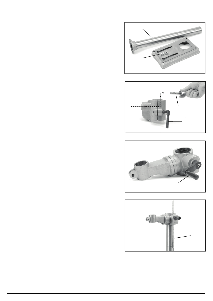
8.1 BASE TO COLUMN - FIG. 1
Align the column (B) onto the base (A) and secure
with the four 16mm bolts (C).
NOTE: Do not overtighten the bolts as this may crack
the casting.
8.2 TABLE BRACKET - FIGS. 2 - 5
Loosely screw locking handle (D) into rear of
the table bracket. Pass the pinion gear (E) inside the
table bracket and pass the shaft out through the
housing side. The pinion gear shaft has one flat side
on which the crank handle (F) secures. Tighten the
locking grub screw with a 3mm hex. key.
NOTE: The toothed rack (G) must be orientated so
the larger non toothed section is upper most.
Position the rack (G) against the column and pass
the table bracket over.
Align the teeth on the rack with those of the worm
gear inside the table arm.
When the gear and rack teeth are intermeshed,
the rack and table arm can be lowered over/down the
column.
NOTE: The rack must be held in position while
lowering to avoid movement.
Locate the bottom end of the rack into the top edge of
the column base. The bevelled edge holds the rack
against the column.
Tighten the table height locking handle.
FIG.1
FIG.2
FIG.3
(B)
(C)
(E)
(F)
- 12 -
FIG.4
Page 13
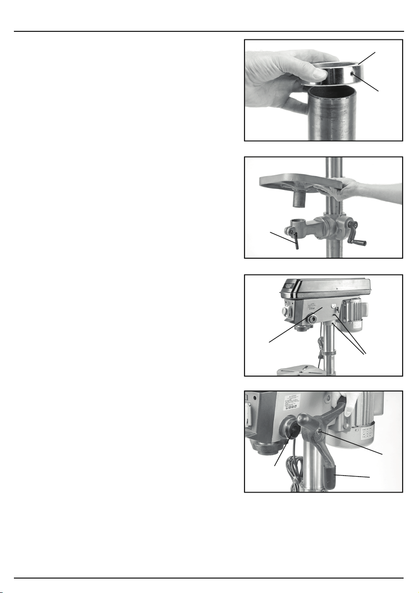
8. PREPARING THE DRILL
Slide the column ring (H) over the column and
locate the bevel on the top edge of the rack into
the bevelled rim of the ring. Tighten grub screw
(I) to secure.
NOTE: Adjust the table arm height to suit and
position centrally over the base before securing
the locking handle.
8.3 TABLE - FIG. 6
Slot the table into the table bracket and tighten
locking handle (J).
8.4 HEADSTOCK - FIG. 7
WARNING: The headstock assembly poses a
significant health and safety hazard while being
lifted and positioned into place. Seek assistance.
Lift the headstock (K) onto the top of the column.
When aligned and located down onto the column
fully, tighten grub screws (L) with the hex. key
supplied.
NOTE: Adjust the drill head over the table and base
before securing. The use of a plumb bob may be
beneficial to improve accuracy.
8.5 PLUNGE HANDLES - FIG. 8
Locate the plunge handle assembly (M) onto
the hub ensuring locating pin (N) is in position.
Secure with the hex. socket head bolt and
washer (O).
(H)
(I)
FIG.5
(J)
FIG.6
(K)
(L)
- 13 -
FIG.7
(O)
(N)
(M)
FIG.8
Page 14
9. SETTING THE DRILL
- 15 -
FIG.12
FIG.13FIG.14
NOTE:
Remove the plug from the socket before
carrying out adjustment, servicing or maintenance.
9.1 SPINDLE SPEED ADJUSTMENT
FIGS. 12 - 14
This drilling machine is equipped with 16 drilling speeds.
Remove the pulley cover securing screw.
Select the speed most suitable for the intended
application
†
.
Loosen both the locking knobs (V) and adjust the
motor tension lever (W) releasing the tautness across
the drive belts.
Move the belt to the corresponding sections of the
motor, intermediate and spindle pulleys ensuring the
belts remain horizontal.
Apply pressure to the motor tension lever (W) to
tension the drive belt. With the correct tension
achieved. Tighten both locking knobs (V).
Gently lower the pulley cover before tightening pulley
cover securing screw.
Never attempt to operate the drilling machine with the
pulley cover open or not fully secured.
CAUTION: Over tensioning the drive belt will
accelerate belt wear, increase the loading on drive
bearings and the motor possibly leading to premature
failure. Under tensioning the drive belt will lead to the
drive belt slipping and increased noise.
†
As a general rule material with a softer composition
can be drilled faster as they cut more easily. Harder
materials require a slower speed as attempting to
make the hole at a high speed will result in the drill bit
over heating which may result in a poorly finished hole,
the bit annealing or the bit breaking.
Drilling wood too slowly can cause splintering.
MOTOR
PULLEY
INTERMEDIATE
PULLEY
SPINDLE
PULLEY
A
B
C
D
E
1
2
3
4
1
2
3
4
5
BD650/16E
DP650/16E
Slow
1
Fast
16
Setting
1
2
3
4
5
6
7
8
9
10
11
12
13
14
15
16
Speed
210 min
-1
280 min
-1
320 min
-1
420 min
-1
500 min
-1
540 min
-1
800 min
-1
830 min
-1
1,110 min
-1
1,290 min
-1
1,350 min
-1
1,580 min
-1
2,050 min
-1
2,180 min
-1
2,580 min
-1
3,340 min
-1
Drive Belt Position
Spindle
A - 1
A - 1
B - 2
B - 2
C - 3
A - 1
E - 5
D - 4
E - 5
C - 3
B - 2
D - 4
E - 5
C - 3
D - 4
E - 5
Motor
4 - 4
3 - 3
4 - 4
3 - 3
4 - 4
2 - 2
4 - 4
3 - 3
3 - 3
2 - 2
1 - 1
2 - 2
2 - 2
1 - 1
1 - 1
1 - 1
Slow
1
Fast
16
Setting
1
2
3
4
5
6
7
8
9
10
11
12
13
14
15
16
Speed
210 min
-1
280 min
-1
320 min
-1
420 min
-1
500 min
-1
540 min
-1
800 min
-1
830 min
-1
1,110 min
-1
1,290 min
-1
1,350 min
-1
1,580 min
-1
2,050 min
-1
2,180 min
-1
2,580 min
-1
3,340 min
-1
Drive Belt Position
Spindle
A - 1
A - 1
B - 2
B - 2
C - 3
A - 1
E - 5
D - 4
E - 5
C - 3
B - 2
D - 4
E - 5
C - 3
D - 4
E - 5
Motor
4 - 4
3 - 3
4 - 4
3 - 3
4 - 4
2 - 2
4 - 4
3 - 3
3 - 3
2 - 2
1 - 1
2 - 2
2 - 2
1 - 1
1 - 1
1 - 1
(V)
(V)
(W)
8. PREPARING THE DRILL
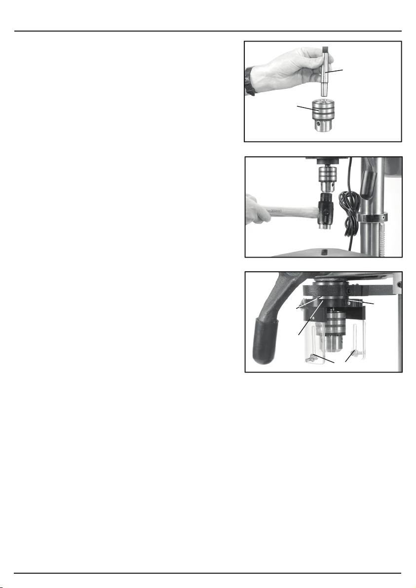
8.6 CHUCK AND ARBOR - FIGS. 9 - 10
The drill chuck, arbor and headstock spindle join
together with an interference fit formed by the matched
tapers of the mating surfaces.
Ensure all mating surfaces are clean as any debris will
cause the taper to miss-align possibly resulting in the
(Q)
(P)
chuck or arbor coming loose creating a potential hazard.
Using the chuck key provided open the chuck until the jaws
are completely recessed and protected from damage.
Insert the short taper end of the arbor (P) into the back
of chuck (Q). A sharp tap with a soft blow mallet will
securely join them together.
NOTE: Ensure the chuck is on a surface that will not
absorb the force of the mallet. If the chuck does not
mate securely, repeat the process.
Insert the long taper end of arbor (P) into the spindle.
Rotate the chuck assembly until the arbor locates
allowing complete insertion.
Tap the chuck to securely locate it in place.
8.7 CHUCK GUARD - FIG. 11
Loosen the cross slot machine screw and nut (R).
Pass the chuck guard (S) over the chuck onto collar
(T). When located fully and aligned on the collar,
tighten the machine screw and nuts to secure the
chuck guard in place.
NOTE: Do not over tighten as it may damage the guard.
To adjust the lower acrylic guard section down and fully
cover the chuck and drill bits, loosen wing nuts (U).
When adjustment is complete, tighten the locking nuts.
NOTE: The chuck guard shall be inspected before
each use to determine effectiveness and correct
functionality.
The chuck guard shall be adjusted and positioned between the chuck and operator for all processes.
Replace a damaged or missing chuck guard before continuing to use the drilling machine.
8.8 BENCH/FLOOR MOUNTING
Securely bolt the drilling machine to a work bench or other secure surface as appropriate through
the various points in the base (fixings are not supplied). Suitable fixings should be sourced
applicable to the load and mounting surface. Ensure there is enough clear space around the
drilling machine to accommodate larger items which may be drilled.
Ensure the load created by the drilling machine, operator and workpiece combined will not
compromise the integrity of the intended mounting surface/floor space.
FIG.9
FIG.10
(T)
(R)
(S)
FIG.11
(U)
- 14 -
Page 15
9. SETTING THE DRILL
NOTE:
Remove the plug from the socket before
carrying out adjustment, servicing or maintenance.
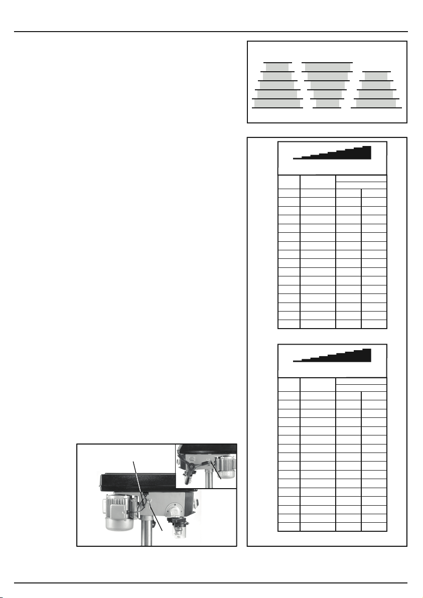
9.1 SPINDLE SPEED ADJUSTMENT
FIGS. 12 - 14
This drilling machine is equipped with 16 drilling speeds.
Remove the pulley cover securing screw.
Select the speed most suitable for the intended
application
Loosen both the locking knobs (V) and adjust the
motor tension lever (W) releasing the tautness across
the drive belts.
Move the belt to the corresponding sections of the
motor, intermediate and spindle pulleys ensuring the
belts remain horizontal.
Apply pressure to the motor tension lever (W) to
tension the drive belt. With the correct tension
achieved. Tighten both locking knobs (V).
Gently lower the pulley cover before tightening pulley
cover securing screw.
Never attempt to operate the drilling machine with the
pulley cover open or not fully secured.
CAUTION: Over tensioning the drive belt will
accelerate belt wear, increase the loading on drive
bearings and the motor possibly leading to premature
failure. Under tensioning the drive belt will lead to the
drive belt slipping and increased noise.
†
As a general rule material with a softer composition
can be drilled faster as they cut more easily. Harder
materials require a slower speed as attempting to
make the hole at a high speed will result in the drill bit
over heating which may result in a poorly finished hole,
the bit annealing or the bit breaking.
Drilling wood too slowly can cause splintering.
†
.
(V)
(V)
(W)
SPINDLE
PULLEY
E
D
C
B
A
FIG.12
Setting
BD650/16E
Setting
DP650/16E
FIG.13FIG.14
INTERMEDIATE
PULLEY
Slow
1
Speed
210 min
1
2
280 min
3
320 min
4
420 min
5
500 min
6
540 min
7
800 min
8
830 min
9
1,110 min
10
1,290 min
11
1,350 min
12
1,580 min
13
2,050 min
14
2,180 min
15
2,580 min
16
3,340 min
Slow
1
Speed
210 min
1
2
280 min
3
320 min
4
420 min
5
500 min
6
540 min
7
800 min
8
830 min
9
1,110 min
10
1,290 min
11
1,350 min
12
1,580 min
13
2,050 min
14
2,180 min
15
2,580 min
16
3,340 min
5
4
3
2
1
Drive Belt Position
Spindle
-1
A - 1
-1
A - 1
-1
B - 2
-1
B - 2
-1
C - 3
-1
A - 1
-1
E - 5
-1
D - 4
-1
E - 5
-1
C - 3
-1
B - 2
-1
D - 4
-1
E - 5
-1
C - 3
-1
D - 4
-1
E - 5
Drive Belt Position
Spindle
-1
A - 1
-1
A - 1
-1
B - 2
-1
B - 2
-1
C - 3
-1
A - 1
-1
E - 5
-1
D - 4
-1
E - 5
-1
C - 3
-1
B - 2
-1
D - 4
-1
E - 5
-1
C - 3
-1
D - 4
-1
E - 5
MOTOR
PULLEY
4
3
2
1
Fast
16
Motor
4 - 4
3 - 3
4 - 4
3 - 3
4 - 4
2 - 2
4 - 4
3 - 3
3 - 3
2 - 2
1 - 1
2 - 2
2 - 2
1 - 1
1 - 1
1 - 1
Fast
16
Motor
4 - 4
3 - 3
4 - 4
3 - 3
4 - 4
2 - 2
4 - 4
3 - 3
3 - 3
2 - 2
1 - 1
2 - 2
2 - 2
1 - 1
1 - 1
1 - 1
- 15 -
Page 16
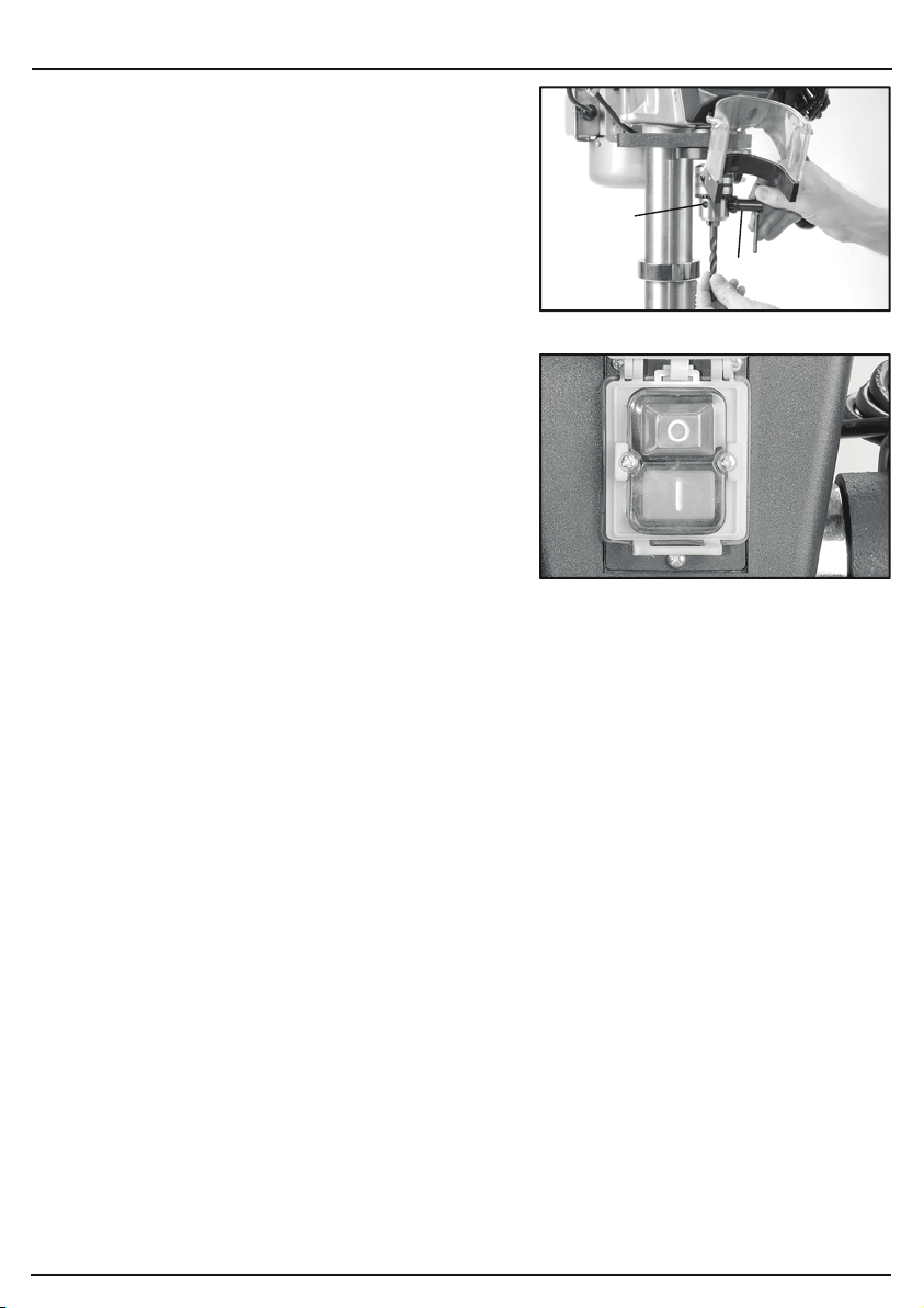
FIG.17
FIG.18
9. SETTING THE DRILL
- 17 -
9.4 WORK TABLE ADJUSTMENT -
FIGS. 17 - 18
For versatility, the work table (Z) can be raised or
lowered, tilted ±45° or rotated 360° around the column.
To tilt the table, tighten nut (AA) clockwise until the
locating pin can be removed from the casting. Store in
a safe location. Loosen the 24mm bolt (AB).
Adjust the table’s degree of tilt and re-secure with
locking bolt (AB). Use the scale as a guide.
Alternatively use a protractor off the table to the drill bit
for more accuracy.
When the table is back in a level position insert the
location pin for the factory setting. Move the nut along
the thread until the end of the thread is protected by
the nut, allowing use of a small hammer to tap the pin
in place.
To raise/lower the table working height, loosen locking
handle (AC) and turn the height adjustment crank
handle (AD) to raise or lower the table. Alternatively
while locking handle (AC) is loose the table can be
rotated 180° to further increase the distance between
the chuck and workpiece. When the adjustments are
complete re-secure locking handle (AC).
The slots in the work table and base can
accommodate locking bolts to secure a small vice
enabling safe clamping of the workpiece.
CAUTION: A drill bit snagging on a piece of work will
violently grab the piece of material, whipping it round
and is likely to result in personal injury. Always ensure
the workpiece is securely clamped.
(Z)
(AC)
(AD)
(AB)
(AA)
9. SETTING THE DRILL
9.2 DRILL BIT INSTALLATION/
REPLACEMENT - FIG. 15
The drilling machine is equipped with a geared chuck
and a separate key to secure the bit in the chuck
jaws.
Selection of the correct accessory is dependent on
material type and the intended application.
Ensure the selected accessory is suitable and speed
compatible with the drilling machine.
Place the bit into the chuck. Insert the chuck key (X)
into apertures (Y) engaging the teeth.
Rotate the key clockwise to grip. All three apertures
should be tightened to make certain of a firm grip.
Always use a good quality sharp drill bit/cutter.
WARNING: The drill bit will be hot after use.
9.3 NO-VOLT SWITCH - FIG. 16
In the event of a power supply disruption the
machine will require manually restarting once
power has been returned.
To switch the machine on, press the green button
marked ‘I’.
To switch the machine off, press the red button
marked ‘O’. However, the yellow cover with integral
red stop button must be left covering the switches
so, in the event of an accident or emergency striking
the stop button will activate the off switch.
Prior to starting the drilling machine make a visual
check, to ensure the guards are in place and
correctly functioning, the bit is correctly installed
with the chuck key removed and no other parts
are damaged proving a potential hazard.
Ensure all locking handles are tight prior to starting
the drilling machine.
FIG.15
FIG.16
(Y)
(X)
- 16 -
Page 17
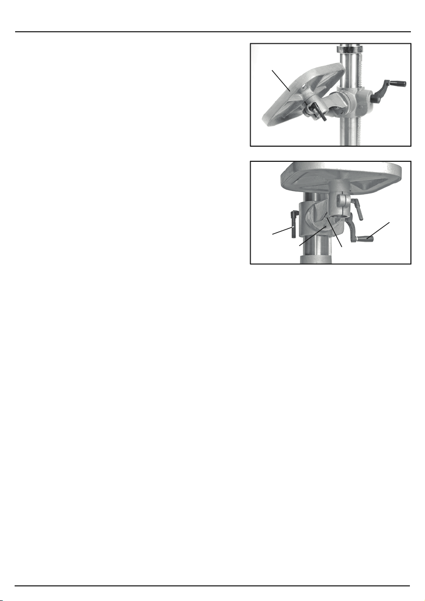
9. SETTING THE DRILL
9.4 WORK TABLE ADJUSTMENT -
FIGS. 17 - 18
For versatility, the work table (Z) can be raised or
lowered, tilted ±45° or rotated 360° around the column.
To tilt the table, tighten nut (AA) clockwise until the
locating pin can be removed from the casting. Store in
a safe location. Loosen the 24mm bolt (AB).
Adjust the table’s degree of tilt and re-secure with
locking bolt (AB). Use the scale as a guide.
Alternatively use a protractor off the table to the drill bit
for more accuracy.
When the table is back in a level position insert the
location pin for the factory setting. Move the nut along
the thread until the end of the thread is protected by
the nut, allowing use of a small hammer to tap the pin
in place.
To raise/lower the table working height, loosen locking
handle (AC) and turn the height adjustment crank
handle (AD) to raise or lower the table. Alternatively
while locking handle (AC) is loose the table can be
rotated 180° to further increase the distance between
the chuck and workpiece. When the adjustments are
complete re-secure locking handle (AC).
The slots in the work table and base can
accommodate locking bolts to secure a small vice
enabling safe clamping of the workpiece.
CAUTION: A drill bit snagging on a piece of work will
violently grab the piece of material, whipping it round
and is likely to result in personal injury. Always ensure
the workpiece is securely clamped.
(Z)
FIG.17
(AC)
FIG.18
(AA)
(AD)
(AB)
- 17 -
Page 18
- 19 -
10. TROUBLESHOOTING
10.1 TROUBLESHOOTING
WARNING: For your safety always turn the main switch on the machine “off” and remove the plug
from the power supply before carrying out any maintenance or troubleshooting.
Machine will not
start.
1. Fuse.
2. Other.
1. Replace/reset time delay fuse
or circuit breaker.
2. Return to an authorised
service agent for diagnosis.
Noisy operation.
Problem Cause Remedy
1. Incorrect belt tension.
2. Dry spindle.
3. Loose spindle pulley or motor
pulley.
1. Adjust tension.
2. Lubricate spindle with grease.
3. Tighten set screws in pulleys.
1. Incorrect speed.
2. Swarf not coming out of hole.
3. Blunt bit.
4. Feeding too slow.
5. Not lubricated.
1. Change speed.
2. Retract bit frequency to clear
swarf.
3. Sharpen or replace bit.
4. Feed fast enough to allow drill
to cut.
5. Lubricate bit.
1. Bent bit.
2. Worn spindle bearings.
3. Bit not properly installed in chuck.
4. Chuck not properly installed.
1. Use a straight bit.
2. Return to an authorised service
agent.
3. Install bit centrally.
4. Refit chuck properly.
1. Workpiece pinching bit or
excessive feed pressure.
2. Improper belt tension.
1. Support or re-clamp workpiece.
2. Adjust tension.
Bit burns or smokes.
Excessive drill
run-out or wobble.
Drill binds in
workpiece.
9. SETTING THE DRILL
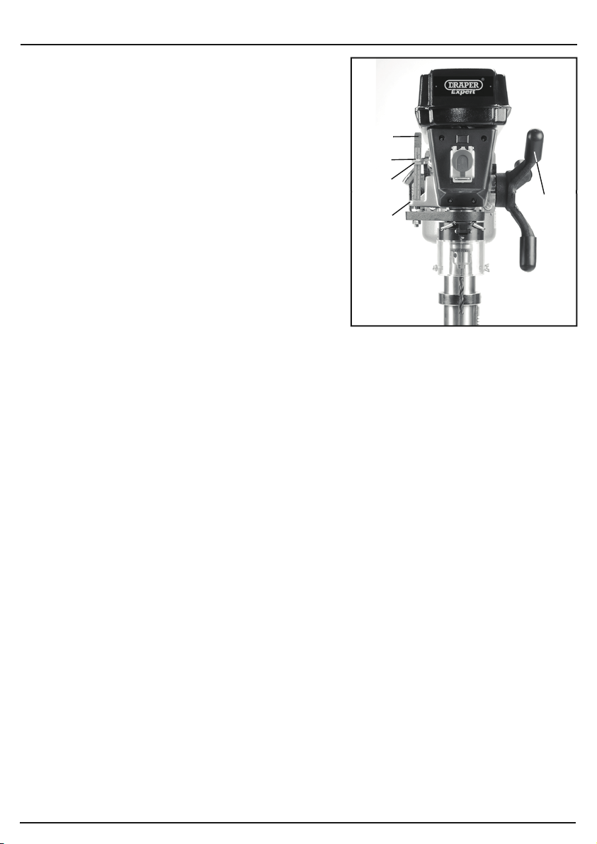
9.5 GENERAL DRILLING - FIG. 19
For repeated drilling to a consistent depth, set the
depth stop facility (AE).
As a guide the depth is indicated on the scale.
NOTE: For accuracy, set up the depth using a steel
rule.
Lower the chuck and drill bit to the required position by
rotating the plunge handles (AF) anti-clockwise.
Set the position with nut (AG) against the stop (AH)
and lock with nut (AI).
Use a scrap piece of material to test before beginning
on the workpiece.
When drilling metal it is good practice to use a cutting
fluid to aid lubrication, swarf removal and as a coolant.
This will result in increased cutting performance and
help prolong the life of the bit. A few drops of oil will
suffice in the absence of a specific cutting fluid.
9.6 DUST AND SWARF
All wood dust (including dust from composites like
chipboards and fibre boards etc) is hazardous to
health: it can affect the nose, the respiratory system
and the skin. For example MDF (medium density
fibreboard) which contains formaldehyde is a
known carcinogen.
A correctly fitted dust mask, suitable for the activity
and in accordance to the relevant standard, must
be worn.
For work activities involving exposure to fine wood
dust a mask rated to at least FFP2 should be used.
Swarf produced by metal cutting is extremely sharp.
Take care when breaking the chips/clearing the bit.
(AE)
(AI)
(AG)
(AH)
FIG.19
(AF)
- 18 -
Page 19

10. TROUBLESHOOTING
10.1 TROUBLESHOOTING
WARNING: For your safety always turn the main switch on the machine “off” and remove the plug
from the power supply before carrying out any maintenance or troubleshooting.
Problem Cause Remedy
Machine will not
start.
Noisy operation.
Bit burns or smokes.
Excessive drill
run-out or wobble.
Drill binds in
workpiece.
1. Fuse.
2. Other.
1. Incorrect belt tension.
2. Dry spindle.
3. Loose spindle pulley or motor
pulley.
1. Incorrect speed.
2. Swarf not coming out of hole.
3. Blunt bit.
4. Feeding too slow.
5. Not lubricated.
1. Bent bit.
2. Worn spindle bearings.
3. Bit not properly installed in chuck.
4. Chuck not properly installed.
1. Workpiece pinching bit or
excessive feed pressure.
2. Improper belt tension.
1. Replace/reset time delay fuse
or circuit breaker.
2. Return to an authorised
service agent for diagnosis.
1. Adjust tension.
2. Lubricate spindle with grease.
3. Tighten set screws in pulleys.
1. Change speed.
2. Retract bit frequency to clear
swarf.
3. Sharpen or replace bit.
4. Feed fast enough to allow drill
to cut.
5. Lubricate bit.
1. Use a straight bit.
2. Return to an authorised service
agent.
3. Install bit centrally.
4. Refit chuck properly.
1. Support or re-clamp workpiece.
2. Adjust tension.
- 19 -
Page 20
11. MAINTENANCE
11.1 MAINTENANCE
Regular inspection and cleaning reduces the necessity for maintenance operations and will keep
your tool in good working condition.
The motor must be correctly ventilated during tool operation. For this reason avoid blocking the air
inlets. After use disconnect the tool from the power supply and vacuum the ventilation slots.
If the replacement of the supply cord is necessary, this has to be done by the manufacturer or his
agent in order to avoid a safety hazard.
At regular interval, lubricate the spindle with a medium purpose grease. With the pulley cover
open, pack the grease down the centre of the front pulley. Operate the plunger mechanism and
brush a thin film of grease on the quill. Clean any debris built up in the pulley housing. Spray a
general purpose lubricating agent/rust inhibitor on the other moving parts and machined surfaces.
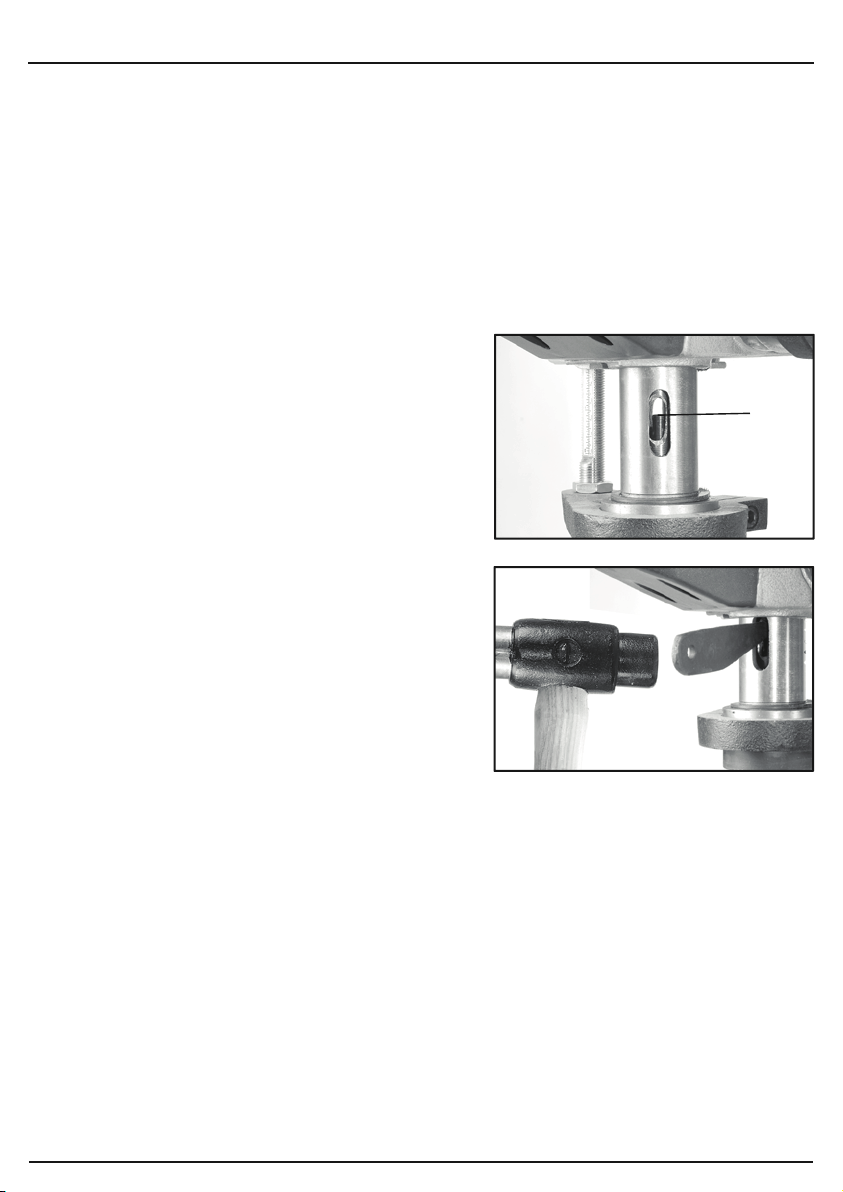
11.2 ARBOR REMOVAL - FIGS. 20 - 21
To aid removal of the arbor from the spindle a drift key
is supplied.
Lower the spindle with the plunge handles to expose
slot (AJ). Rotate the spindle to align the inner and
outer slots.
Insert the drift key and allow the spindle to raise. Tap
the drift key while supporting the chuck.
FIG.20
- 20 -
FIG.21
Page 21

12. OPTIONAL ACCESSORIES
12.1 OPTIONAL ACCESSORIES
A range of drill bits and accessories are available from your local Draper Stockist.
Please visit our website for details: www.drapertools.com
- 21 -
Page 22
- 23 -
14. DISPOSAL
14.1 DISPOSAL
– At the end of the machine’s working life, or when it can no longer be repaired, ensure that it is
disposed of according to national regulations.
– Contact your local authority for details of collection schemes in your area.
In all circumstances:
•
Do not dispose of power tools with domestic waste.
•
Do not incinerate.
•
Do not abandon in the environment.
•
Do not dispose of WEEE* as unsorted municipal waste.
* Waste Electrical & Electronic Equipment.
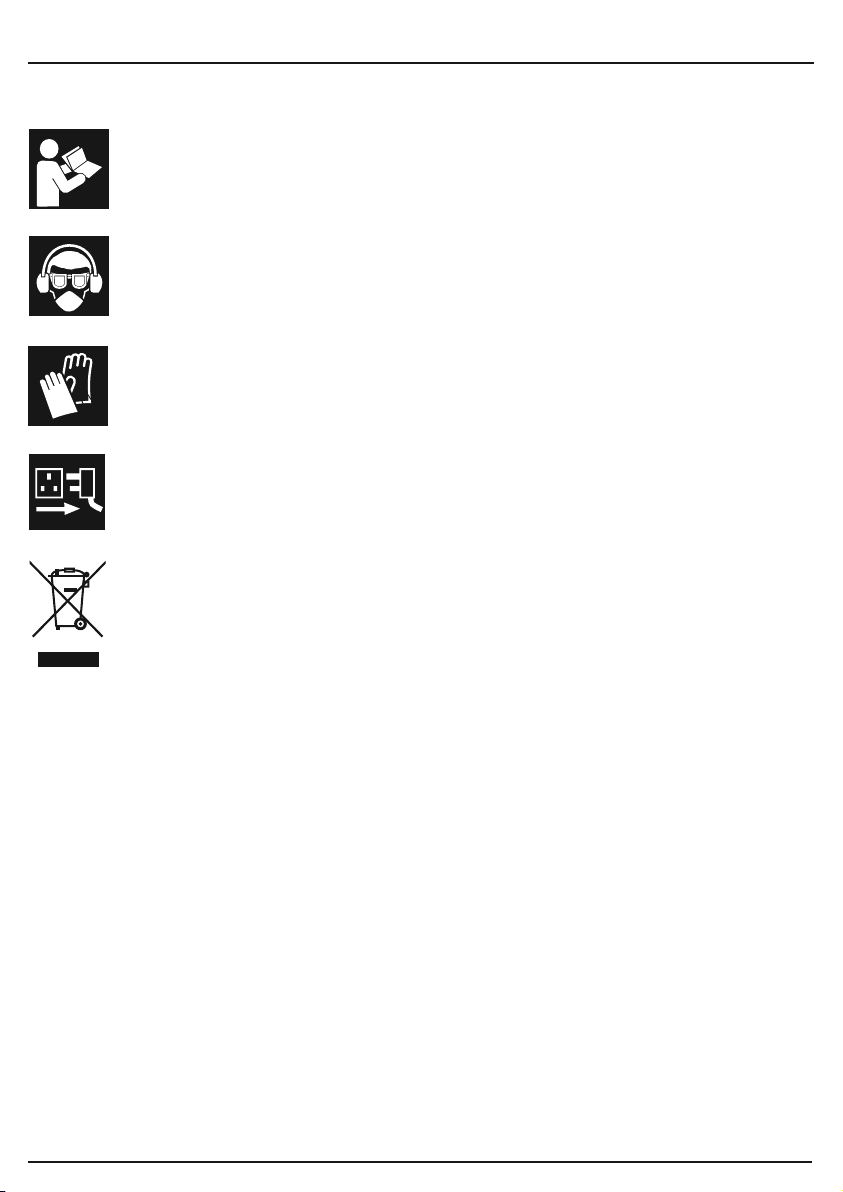
13. EXPLANATION OF SYMBOLS
13.1 EXPLANATION OF SYMBOLS
✘
Warning!
Read the instruction manual.
Warning!
Wear suitable eye/face/ear protection.
Warning!
Do not wear gloves.
Warning!
Remove plug from power
supply before maintenance.
Do not dispose of WEEE*
unsorted municipal waste.
- 22 -
Page 23

14. DISPOSAL
14.1 DISPOSAL
– At the end of the machine’s working life, or when it can no longer be repaired, ensure that it is
disposed of according to national regulations.
– Contact your local authority for details of collection schemes in your area.
In all circumstances:
Do not dispose of power tools with domestic waste.
•
Do not incinerate.
•
Do not abandon in the environment.
•
Do not dispose of WEEE* as unsorted municipal waste.
•
* Waste Electrical & Electronic Equipment.
- 23 -
Page 24

CONTACTS
Draper Tools Limited
UK: Hursley Road, Chandler's Ford, Eastleigh,
Hampshire. SO53 1YF. U.K.
EU: Oude Graaf 8
6002 NL Weert (NL)
Helpline: (023) 8049 4344
Sales Desk: (023) 8049 4333
Internet: drapertools.com
E-mail: [email protected]
General Enquiries: (023) 8026 6355
Service/Warranty Repair Agent:
For aftersales servicing or warranty repairs, please contact the
Draper Tools Helpline for details of an agent in your local area.
YOUR DRAPER STOCKIST
JLTL0422
©Published by Draper Tools Limited.
No part of this publication may be reproduced, stored in a retrieval system or transmitted in any form or by any means,
electronic, mechanical photocopying, recording or otherwise without prior permission in writing from Draper Tools Ltd.
 Loading...