

Page 1

EN
Original Instructions
Version 1
16” WALL
MOU NT ED
FAN
70975
Page 2
1. Preface
EN
EN
These are the original product instructions. This
document is part of the product; retain it for the life
of the product, passing it on to subsequent holders.
Read this manual in full before attempting to
assemble, operate or maintain this product.
This Draper Tools manual describes the purpose
of the product and contains all the necessary
information to ensure its correct and safe use.
Following all the instructions and guidance in
this manual will ensure the safety of both the
product and the operator and increase the
lifespan of the product.
1.1 Product Reference
User Manual for: 230V Oscillating Wall Mounted
Fan with Remote Control, 16”/400mm, 3 Speed
Stock No: 70975
Part No: FAN7C
1.2 Revisions
Version 1: August 2022
First release
As our manuals are continually updated, always ensure
that the latest version is used.
Please visit drapertools.com/manuals for the latest
version of this manual and the associated parts list, if
applicable.
All photographs and drawings within this manual are
supplied by Draper Tools to help illustrate correct
operation of the product.
Every eort has been made to ensure the
information contained in this manual is accurate.
However, Draper Tools reserves the right to amend
this document without prior warning. Always use the
latest version of the product manual.
1.3 Understanding the Safety Content of
This Manual
WARNING!
in personal injury or death.
CAUTION! – Situations or actions that may result
in damage to the product or surroundings.
Important: – Information or instructions of particular
importance.
– Situations or actions that may result
1.4 Copyright © Notice
Copyright © Draper Tools Limited.
Permission is granted to reproduce this manual for
personal and educational use ONLY. Commercial
copying, redistribution, hiring or lending is strictly
prohibited.
No part of this manual may be stored in a retrieval system
or transmitted in any other form or means without written
permission from Draper Tools Limited.
In all cases, this copyright notice must remain intact.
2. Contents
1. Preface 2
1.1 Product Reference 2
1.2 Revisions 2
1.3 Understanding the Safety Content of This Manual 2
1.4 Copyright © Notice 2
2. Contents 3
3. Warranty 4
4. Product Introduction 5
4.1 Intended Use 5
4.2 Specication 5
5. Health and Safety Information 6
5.1 General Health and Safety Precautions For This Product 6
5.2 Battery Safety 7
5.3 Connection to the Power Supply 7
5.4 Connection to the Power Supply (Charger) 7
6. Identication and Unpacking 8
6.1 Product Overview 8
6.2 What’s in the Box? 9
6.3 Packaging 9
7. Operating Instructions 10
8. Installation Instructions 12
8.1 Installing the Fan Onto a Wall 12
8.2 Setting the Fan Tilt Angle 12
9 . Operating Instructions 13
9.1 Control Panel Overview 13
9.2 Power and Speed Selection 13
9.3 Oscillation 13
9.4 Fan Modes 14
9.5 Shutdown Timer 15
10 . The Remote Control 16
10.1 The Remote Control 16
10.2 Replacing the Batteries 16
10.3 Mode Selection 16
10.4 Setting the Timer 16
11 . Maintenance and Storage 17
12. Spares, Returns and Disposal 18
13. Explanation of Symbols 19
– 2 –
– 3 –
Page 3

EN
3. Warranty
EN
4. Product Introduction
Draper Tools products are carefully tested and inspected
before shipment and are guaranteed to be free from
defective materials and workmanship.
Should the tool develop a fault, return the complete tool
to your nearest distributor or contact Draper Tools
directly. Contact information can be found at the back of
this manual.
Proof of purchase must be provided.
If, upon inspection, it is found that the fault occurring is
due to defective materials or workmanship, repairs will
be carried out free of charge. This warranty period covers
parts and labour for 12 months from the date of
purchase. Where tools have been hired out, the warranty
period covers 90 days from the date of purchase.
This warranty does not apply to any consumable parts,
batteries or normal wear and tear, nor does it cover any
damage caused by misuse, careless or unsafe handling,
alterations, accidents, or repairs attempted or made by
any personnel other than the authorised Draper Tools
repair agent.
In all cases, to make a claim for faulty workmanship or
materials within the standard warranty period, please
contact or return the product to the place of purchase.
Proof of purchase may be required.
If the place of purchase is no longer trading or if you
experience any diculties with your warranty, please
contact Customer Services with the product details and
your proof of purchase. Contact details can be found at
the back of this manual.
If the tool is not covered by the terms of this warranty,
repairs and carriage charges will be quoted and charged
accordingly.
This warranty supersedes any other guarantees
expressed or implied and variations of its terms are not
authorised.
Your Draper Tools guarantee is not eective until you can
produce, upon request, a dated receipt or invoice to
verify your purchase within the guarantee period.
Please note that this warranty is an additional benet
and does not aect your statutory rights.
Draper Tools Limited
4.1 Intended Use
This product is designed to improve air circulation in
enclosed spaces and to assist with lowering ambient
temperatures. This product is an oscillating fan intended for
wall mounting only and is supplied with a remote control.
Part of our core range, this product is suitable for regular
use by enthusiasts and tradespersons alike.
WARNING! This product is not a toy and
must be respected.
Read this manual in full before attempting to assemble,
operate or maintain the product and retain it for later use.
4.2 Specication
Stock No. 70975
Part No. FAN7C
Rated voltage: 220–240V
Rated frequency: 50Hz
Rated input: 45W
Fan speed:
Low: 1,050rpm
Medium: 1,150rpm
High: 1,250rpm
Variance: ±100rpm
Fan modes: 3
Blade assembly diameter: 330mm
Guard diameter: 410mm (16” )
3
Airow: 62m
Noise emissions: < 73dB(A)
Timer:
Max. duration: 7.5h
Intervals: 30min
Appliance class: Class II
Dimensions: W 430mm x H 575mm x D 345mm
Weight: 2.3kg
Batteries (remote): 2 x AAA (not supplied)
/min
– 4 –
– 5 –
Page 4

EN
5. Health and Safety Information
EN
5. Health and Safety Information
Important: Read all Health and Safety instructions
before attempting to operate, maintain or repair this
product. Non-compliance with these instructions may
result in injury or damage to the user or the product.
5.1 General Health and Safety
Precautions For This Product
• Observe all standard safety precautions and good
practices when working with electrical equipment.
Important: DO NOT use this product if it is leaking or
damaged in any way. DO NOT attempt to disassemble
a damaged product; contact Draper Tools to discuss
repair and replacement options.
• Before every use, inspect the product for broken,
cracked, loose or corroded parts and leakages.
• This appliance can be used by children aged eight
years and above and by persons with reduced
physical, sensory or mental capabilities or lack of
experience and knowledge if they have been given
supervision or instruction concerning the use of the
appliance in a safe way and understand the hazards
involved.
– Children must not play with the appliance.
– Cleaning and user maintenance must not be
performed by children without supervision.
• DO NOT modify this product in any way and ONLY
use spare parts supplied by Draper Tools.
• This product is for indoor use ONLY.
WARNING! Risk of shock!
– DO NOT allow the fan to come into contact with
water or any other liquid.
– DO NOT use this fan in the vicinity of a bath,
shower, swimming pool or other body of water.
– DO NOT use the fan in wet environments.
– DO NOT touch the fan with wet hands.
• Observe all standard safety precautions and good
practices when working at heights when installing the
product onto a wall.
• Before installing the product onto a wall or surface,
check for active power lines and other hazards within
the wall.
• This product requires W 600 x H 600 x D 650mm of
space when installed.
• ALWAY S install the fan in its upright position.
• Ensure that the fan is not situated in the vicinity of
loose furnishings, clothing, curtains and other loose
items that could get sucked into the air inlet or jam
the fan blades.
• DO NOT install the fan in dusty environments.
– Dust may get caught in the airow and cause air
pollution or gather in and obstruct the fan motor.
• DO NOT install this product in the vicinity of gas
appliances, open ames, and cooling or heating
appliances.
• ALWAY S ensure that the fan is completely assembled
and mounted securely on the wall before switching it on.
• Ensure that the mains outlet to which the product is
connected is accessible at all times.
• Keep the power cable away from sources of heat,
sharp edges and oil.
• DO NOT run the power cable beneath a carpet or rug.
• If the supply cord is damaged, it must be replaced by
Draper Tools or its authorised service agent in order
to avoid a hazard.
• DO NOT carry the fan by the power cable or
disconnect it from a mains outlet by pulling on the
cable.
• DO NOT insert ngers or other foreign objects
through the grille and avoid contact with moving
parts.
• DO NOT attempt to touch the fan blades while they
are in motion.
• ALWAYS switch o the fan, disconnect it from mains
power and allow the fan blades to completely stop
before removing the grille or performing any cleaning
or maintenance or before moving the product.
• NEVER cover any part of the fan.
• Ensure that the air inlet is clear and unobstructed.
• DO NOT use this product with a programmer, timer,
separate remote-control system or any other device
that switches the fan on automatically as it may be
covered or positioned incorrectly when activated and
cause a hazard.
• DO NOT use this fan with an independent, externally
connected speed control device.
• DO NOT leave the fan running unattended.
5.2 Battery Safety
WARNING! ONLY power this product using the
battery type described. DO NOT use or charge
the battery if leakage is evident.
WARNING! NEVER charge non-rechargeable
or damaged batteries.
• DO NOT short-circuit the battery by connecting the
positive and negative terminals while it is outside of the
product.
– Keep the battery away from metallic objects that may
inadvertently allow connection of the terminals.
• DO NOT open, crush or burn the battery as this may
release potentially harmful chemicals.
• DO NOT expose the battery to temperatures greater
than 50°C.
• DO NOT attempt to charge batteries that exhibit a
temperature that is not between 5 and 30°C.
– Allow batteries that are too hot or too cold to
normalise before charging.
• DO NOT expose the battery pack to rain or other wet
conditions.
• ALWAYS remove the battery from the tool before
recycling and dispose of it in accordance with local
regulations.
• If a re occurs, use a CO2 or dry chemical extinguisher.
WARNING! Batteries contain electrolytes, which
are corrosive. Avoid contact with skin.
If contact occurs, ush the area with clean water
and pat it dry. Seek medical attention at the earliest
opportunity. If contact with eyes occurs, ush
immediately with plenty of water ONLY and seek
medical advice at the earliest opportunity.
5.3 Connection to the Power Supply
• This appliance is supplied with an approved plug and
cable for your safety.
• If the power supply cord is damaged, it must be replaced
by Draper Tools, an authorised service agent or similarly
qualied personnel in order to avoid a hazard.
• The damaged or incomplete plug, when cut from the
cable, shall be disabled to prevent connection to a live
electrical outlet.
• This product is Class II* and is designed for connection
to a power supply matching that detailed on the rating
label and compatible with the plug tted.
CAUTION! DO NOT use this product with an
extension lead or multi-socket.
The fuse cover is removable with a small plain slot
screwdriver. The value of the fuse tted is marked on the
pin face of the plug. Should the fuse need replacing,
ensure the substitute is of the correct rating, approved
to BS 1363/A and ASTA or BS Kite marked. This should
only be performed by suitably qualied personnel.
ASTA
BSI
Ensure the fuse cover is replaced before attempting to
connect the plug to an electrical outlet. If the cover is
missing, a replacement must be obtained or the plug
replaced with a suitable type.
*Double Insulated: This product is double insulated
and does not require an earth connection to protect
against electric shock from accessible conductive parts
in the event of failure of the basic insulation.
5.4 Residual Risk
The safety instructions in this manual cannot account
for all possible conditions and situations that may
occur. Exercise common sense and caution when
using this product and protect against any additional
conceivable risks.
– 6 –
– 7 –
Page 5
6. Identication and Unpacking
EN
EN
6. Identication and Unpacking
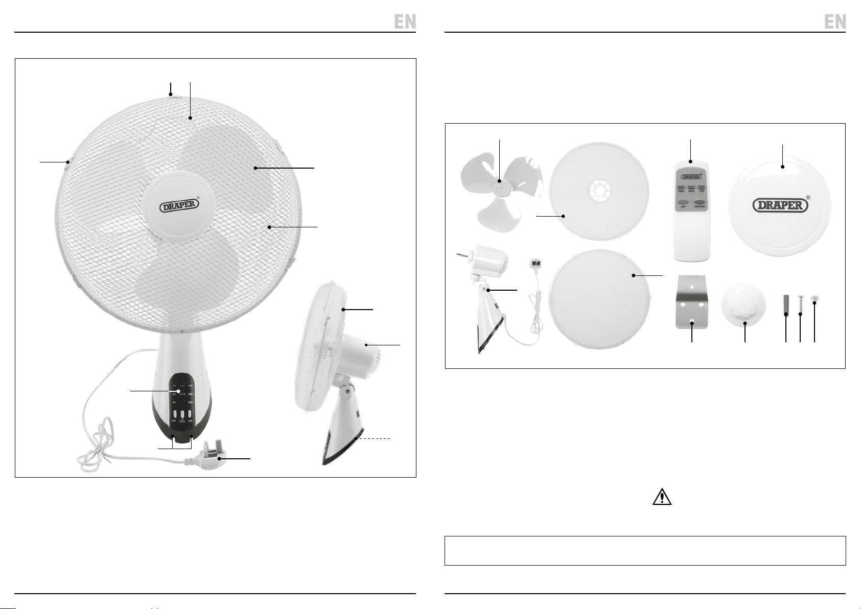
6.1 Product Overview
(6)
(7)
(8)
(3)
(1)
(2)
(4)
6.2 What’s in the Box?
Carefully remove the product from the packaging and
examine it for any signs of damage that may have
occurred during shipment.
(C)
(A)
Before assembling the product, lay the contents out and
check them against the parts shown below. If any part
is damaged or missing, do not attempt to use the
product. Please contact the Draper Helpline; contact
details can be found at the back of this manual.
(G)(D)
(B)
(H) (F) (K) (I)
(E)
(J)
(1) Front grille
(2) Rear grille
(3) Blades
(4) Fan head
(5) Control panel
(6) Grille clips
(5)
(9)
(11)
(7) Upper grille clip
(8) Handle loop
(9) Cable eyes
(10) Base bracket
(11) Power cable and plug
– 8 –
(10)
(A) 1 x Fan body
(B) 1 x Front grille
(C) 1 x Rear grille
(D) 1 x Blade assembly
(E) 1 x Grille cap
(F) 1 x Blade nut
6.3 Packaging
Keep the product packaging for the duration of the
warranty period for reference should the product need to
be returned for repair.
Please visit drapertools.com for our full range of accessories and consumables.
(G) 1 x Remote control
(H) 1 x Wall mounting bracket
(I) 3 x M4 x 25mm screws
(J) 1 x 3mm x 5mm truss-head screw
(K) 3 x Plastic wall plugs (27mm)
WARNING! Keep packaging materials out
of reach of children. Dispose of packaging
correctly and responsibly and in accordance
with local regulations.
– 9 –
Page 6
EN
7. Assembly Instructions7. Assembly Instructions
EN
Important: Read and understand all the safety
instructions listed in this manual before attempting
to assemble or install the product.
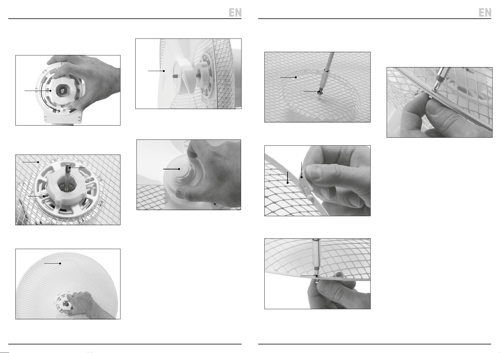
1. Loosen and remove the rear grille nut (12).
(12)
Fig. 1
2. Place the rear grille (C) onto the fan bolt (14) so that the
handle loop (8) is positioned upwards at the rear and
the lower fan head pin (13) sits within the narrow slot.
(C)
(14)
(13)
4. Slide the blade assembly (D) onto the fan bolt so that
the open face is directed to the rear of the fan.
(D)
Fig. 4
Important: Ensure that the attened edge of the bolt
is inserted correctly through the blade assembly.
5. Screw the blade nut (F) securely onto the fan bolt.
(F)
6. Pass the grille cap (E) pin through the centre-most
opening of the front grille so that it sits within the
sunken area and x it in place with the 3 x 5mm
screw (J).
(E)
(J)
Fig. 6
7. Remove the grille safety screw (15) from the front grille
(B) and pull the grille clips (6) outwards to open them.
(6)
(B)
8. Align the grille safety screw holes at the bottom of the
grill frame and hook the upper clip (7) over the top of
the rear grille frame.
9. Use the grille safety screw to attach the front and rear
grilles together and push the grille clips inwards to
hold them in place.
Fig. 9
Fig. 2
3. Replace and tighten the rear grille nut and remove
the protective tubing from the fan bolt.
(8)
Fig. 3
Fig. 5
Important: Rotate the blade nut anticlockwise to
tighten it. DO NOT overtighten the nut.
– 10 –
Fig. 7
The grille safety screw is located at the lowest
position on the front grille.
(15)
Fig. 8
– 11 –
Page 7
8. Installation Instructions
EN
EN
9 . Operating Instructions
Important: Read all the safety instructions before
attempting to install this product.
8.1 Installing the Fan Onto a Wall
Important: The fan requires an area of at least
W 600 x H 600 x D 650mm in order to operate
freely and without obstruction.
CAUTION! Check the immediate area around the
installation point to ensure that there are no
loose items that may become caught in or
otherwise aected by the fan in a manner that
may cause a hazard.
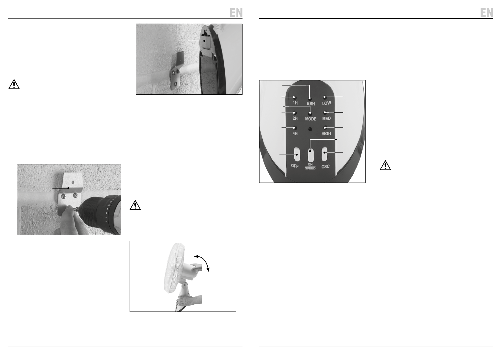
1. Place the wall mounting bracket (H) against the wall or
surface so that the three holes are against the wall and
the bracket extends upwards.
Important: Ensure that there is enough space above
the bracket to accommodate the fan once installed and
that a suitable power outlet is within reach of the plug.
2. Mark the position of the holes and drill using an
appropriate bit.
(H)
Fig. 10
3. Insert the plastic wall plugs and screw the bracket
rmly into place.
4. Hook the fan’s base bracket (10) over the wall
mounting bracket.
(10)
Fig. 11
The cable runs and eyes on the base of the fan can
be used to keep the power cable tidy.
Important: Ensure that the fan sits securely on the
bracket and cannot be pulled away from the wall
easily.
5. Additional xings (not supplied) can also be installed
through any unused cable eyes for extra support.
Important: DO NOT overtighten screws through the
cable eyes as you may damage the product. ALWAYS
use xings appropriate for the installation surface
material.
8.2 Setting the Fan Tilt Angle
WARNING! ALWAYS ensure that the fan is switched
o, disconnected from mains power and has
completely stopped before adjusting the tilt angle.
The vertical tilt angle of the fan can be adjusted by gently
pushing the fan head upwards or downwards. The fan
clicks as it locks into each position.
Important: Before using this product, read and
understand all the safety instructions listed in this
manual. ALWAYS ensure that the fan is securely installed
and that both grilles are tted correctly before use.
The fan must be plugged into an active mains power
supply for use.
9.1 Control Panel Overview
(25)
(26)
(24)
(27)
(28)
(18)
Fig. 13
(18) Fan o button
(19) Fan on/speed button
(20) Fan oscillation button
(21) Low speed indicator
(22) Medium speed indicator
(23) High speed indicator
(24) Mode indicator
(25) 30min timer indicator
(26) 60min timer indicator
(27) 120min timer indicator
(28) 240min timer indicator
(21)
(22)
(23)
(19)
(20)
9.2 Power and Speed Selection
To switch the fan on, press the on/speed button (19).
The fan is equipped with three speed settings:
• Low
• Medium
• High
The fan retains the speed setting active at the time it
was switched o and starts up at this speed.
To advance to the next speed setting, press the on/speed
button again.
To switch o the fan, press the o button (18).
Power and speed selection can be performed using
both the control panel and the remote control.
9.3 Oscillation
The fan head will oscillate left and right if enabled.
To enable oscillation, press the oscillation button (20).
To disable oscillation, press the oscillation button again.
CAUTION! Before enabling oscillation, ensure
that the rotation movement of the fan will not
bring the blades into close proximity with loose
or obstructive objects that may get caught in
the blades or cause a hazard.
Oscillation can be enabled and disabled using both the
control panel and the remote control.
– 12 –
Fig. 12
– 13 –
Page 8
EN
EN
9 . Operating Instructions
9 . Operating Instructions
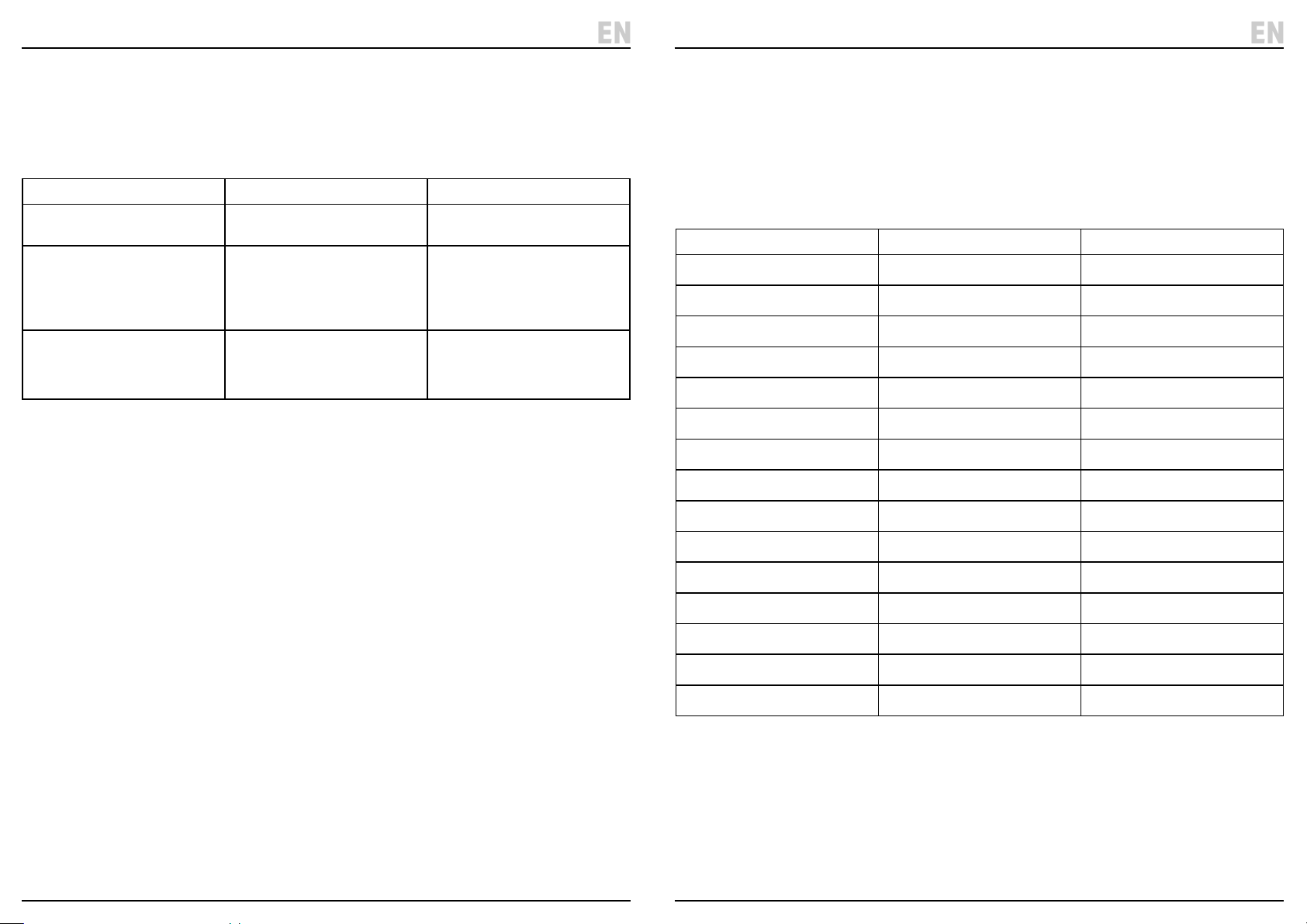
9.4 Fan Modes
The fan is equipped with three modes of operation. Each
mode can operate at each of the three speeds available.
The active mode is identied by the colour of the mode
indicator (18).
Mode Behaviour Indicator colour
Normal The fan maintains a constant air ow
using the chosen speed setting.
Natural The fan cycles between each of the
speed settings that are equal to or
lower than the active setting,
including o. Each cycle lasts
approximately 40 seconds.
Sleep As in Natural mode, but the highest
available fan speed is reduced by
one step every 30 minutes until the
low speed cycle is maintained.
The fan retains the mode that was active at the time
it was switched o and starts up in this mode.
The fan mode is managed using the remote control
ONLY; see 10.3 Mode Selection.
Red
Green
O
9.5 Shutdown Timer
The fan is equipped with a timer that automatically
switches the device o after the congured period.
Shutdown occurs regardless of mode or speed.
The time remaining can be calculated by adding the
values of the illuminated indicators (25) (26) (27) (28) on
the control panel.
The timer period is indicated as follows:
Timer period (min) Illuminated indicators Control panel labels
30 (25) 0.5H
60 (26) 1H
90 (25)(26) 0.5H + 1H
120 (27) 2H
150 (25)(27) 0.5H + 2H
180 (26)(27) 1H + 2H
210 (25)(26)(27) 0.5H + 1H + 2H
240 (28) 4H
270 (25)(28) 0.5H + 4H
As time elapses, the indicators change as appropriate to
indicate the remaining time.
Important: The timer is cancelled if the fan is
switched o before the chosen period has elapsed.
The fan mode is set using the remote control ONLY;
see 10.4 Setting the Timer.
300 (26)(28) 1H + 4H
330 (25)(26)(28) 0.5H + 1H + 4H
360 (27)(28) 2H + 4H
390 (25)(27)(28) 0.5H + 2H + 4H
420 (26)(27)(28) 1H + 2H + 4H
450 (25)(26)(27)(28) 0.5H + 1H + 2H + 4H
– 14 – – 15 –
Page 9
EN
EN
10. The Remote Control
11 . Maintenance and Storage
Important: Some functions are only accessible via the
remote control. Keep it safe.
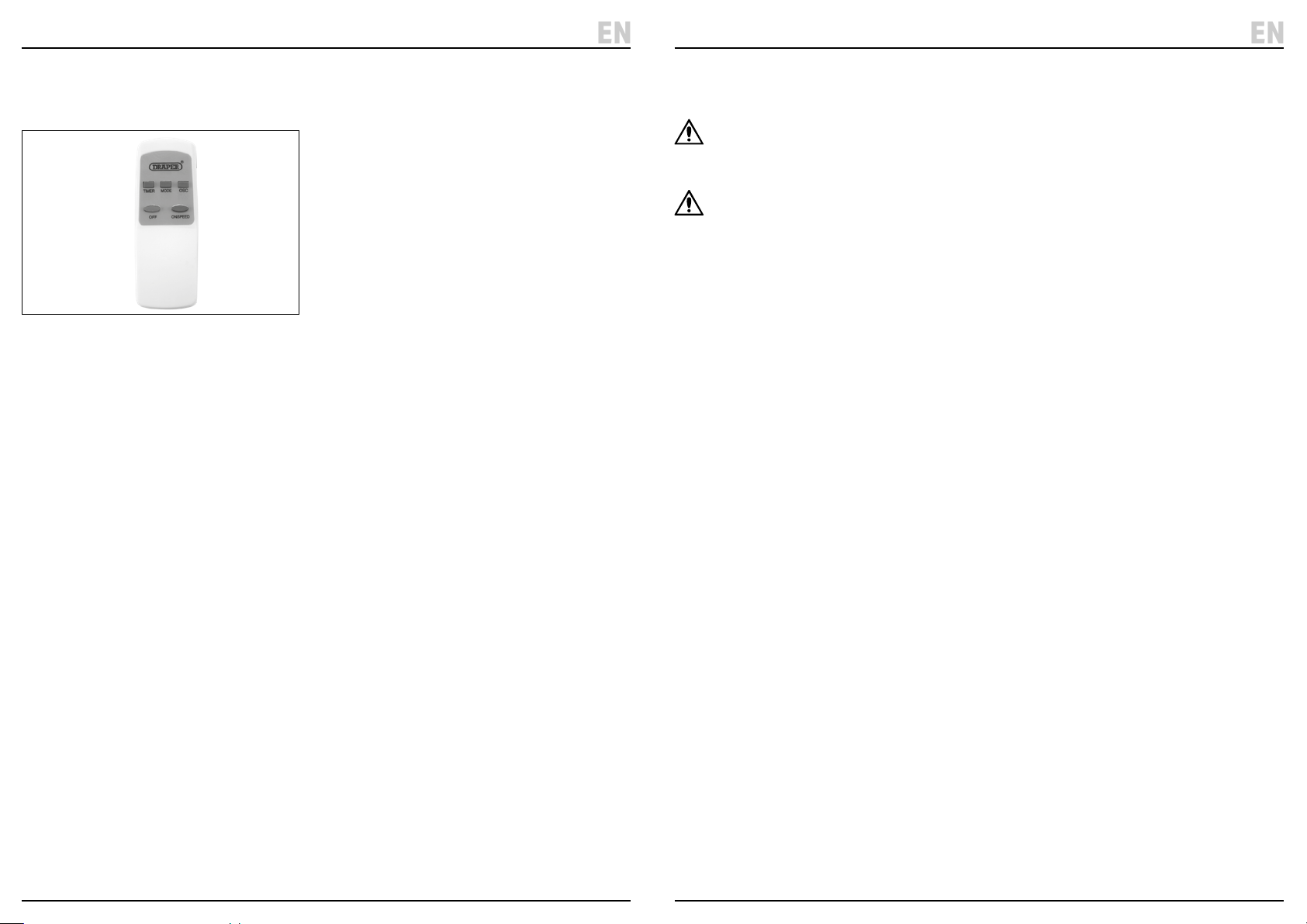
10.1 Remote Control Overview
Fig. 14
(29) Remote o button
(30) Remote on/speed button
(31) Remote oscillation button
(32) Timer button
(33) Mode button
(34) Battery compartment cover
The o (29), on/speed (30) and oscillation (31) buttons
behave in the same way as the corresponding buttons
(18) (19) (20) on the fan control panel.
10.2 Replacing the Batteries
The remote control requires two AAA batteries to
operate. To install or replace the batteries:
1. Slide the battery compartment cover downwards
and away from the remote.
2. Remove any installed batteries and insert two AAA
batteries, observing the correct polarity.
3. Slide the battery compartment cover back into place
until it locks.
Important: ALWAYS dispose of used batteries
responsibly and in accordance with local regulations.
10.3 Mode Selection
The fan is equipped with three airow modes; see 9.4
Fan Modes. The mode must be selected using the
remote control.
The fan retains the mode that was active at the time it
was switched o and starts up in this mode. To select the
next available mode, press the mode button (33).
10.4 Setting the Timer
The fan is equipped with a shutdown timer; see 9.5
Shutdown Timer. The timer must be congured using
the remote control and can be set in 30-minute
increments. The maximum timer period is 450 minutes
(7.5 hours).
The timer must be reset every time the fan is switched on
if it is needed. The fan does NOT remember the timer
congured during the previous operation.
To enable the timer:
1. Press the timer button (32) on the remote control;
this illuminates the 30-minute timer indicator (25)
on the control panel.
2. Press the timer button again to increase the timer
period; the indicators illuminate as appropriate to
show the congured period.
3. To cancel the timer, press the timer button
repeatedly until all timer indicators are o or switch
the fan o.
Important: The timer period cannot be reduced. If a
shorter timer period is required, cancel the timer and
press the timer button until the correct period is
congured.
Important: Read all the safety information listed in this
manual before attempting to maintain, service or repair
this product.
WARNING! ALWAYS ensure that the fan is
switched o, disconnected from mains power
and that the blades have completely stopped
before working on this product.
CAUTION! Remove parts from the fan where
possible before cleaning them to avoid
moisture accessing the motor. Dry parts
thoroughly before reassembly.
• Clean the grilles using a damp cloth ONLY.
• Clean the blade assembly and other plastic parts
using a damp cloth and soapy water ONLY.
• NEVER use solvents or aggressive chemicals for
cleaning as these may damage plastic or insulated
parts of the fan.
• Clean the fan thoroughly before storage.
• When storing the fan, cover it in a plastic bag to
protect it from dust and store it in a clean and dry
location out of reach of children.
• Remove any batteries from the remote control if
it will be stored or unused for extended periods.
– 16 – – 17 –
Page 10
12. Spares, Returns and Disposal
EN
EN
For spare parts, servicing, and repair and replacement
options, please contact the Draper Tools Product
Helpline for details of your nearest authorised agent.
Draper Tools will endeavour to hold any spare parts, if
applicable, for seven years from the date that it sells the
nal matching stock item.
Any servicing or repairs carried out by unauthorised
personnel or installation of spare parts not supplied by
Draper Tools will invalidate your warranty.
At the end of its working life, dispose of the product
responsibly and in line with local regulations. Recycle
where possible.
• DO NOT dispose of this product with domestic waste;
most local authorities provide appropriate recycling
facilities.
• DO NOT burn or mutilate batteries; this may release
toxic or corrosive substances.
• Dispose of the battery in accordance with local
regulations or return it to your warranty agent or
stockist for recycling.
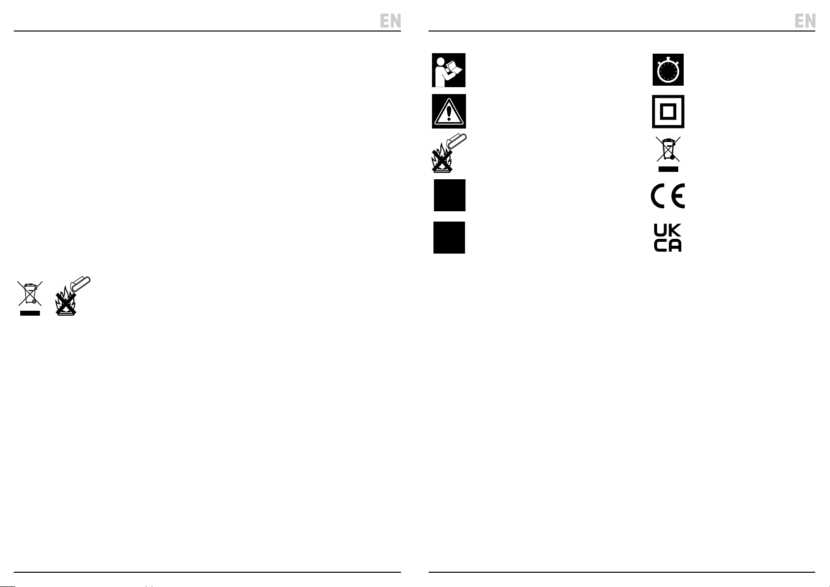
13. Explanation of Symbols
Read the instruction manual
Warning!
Do not incinerate or throw onto re
220-
Rated voltage
240V
3
SPEED
Three operating speeds
7.5h
Shutdown timer (max. 7.5h)
Class II appliance
WEEE –
Waste Electrical & Electronic Equipment
Do not dispose of this product with domestic waste
European conformity
UK Conformity Assessed
– 18 –
– 19 –
Page 11

Contact Details
Draper Tools
Draper Tools Limited
Hursley Road
Chandler’s Ford
Eastleigh
Hampshire
SO53 1YF
UK
Website: drapertools.com
Email: [email protected]
Product Helpline: +44 (0) 23 8049 4344
Telephone Sales Desk: +44 (0) 23 8049 4333
General Enquiries: +44 (0) 23 8026 6355
General Fax: +44 (0) 23 8026 0784
Please contact the Draper Tools Product Helpline for repair and servicing enquiries.
Delta International
Delta International BV
Oude Graaf 8
6002 NL
Weert
Netherlands
© Published by Draper Tools Limited© Published by Draper Tools Limited
 Loading...