

Page 1
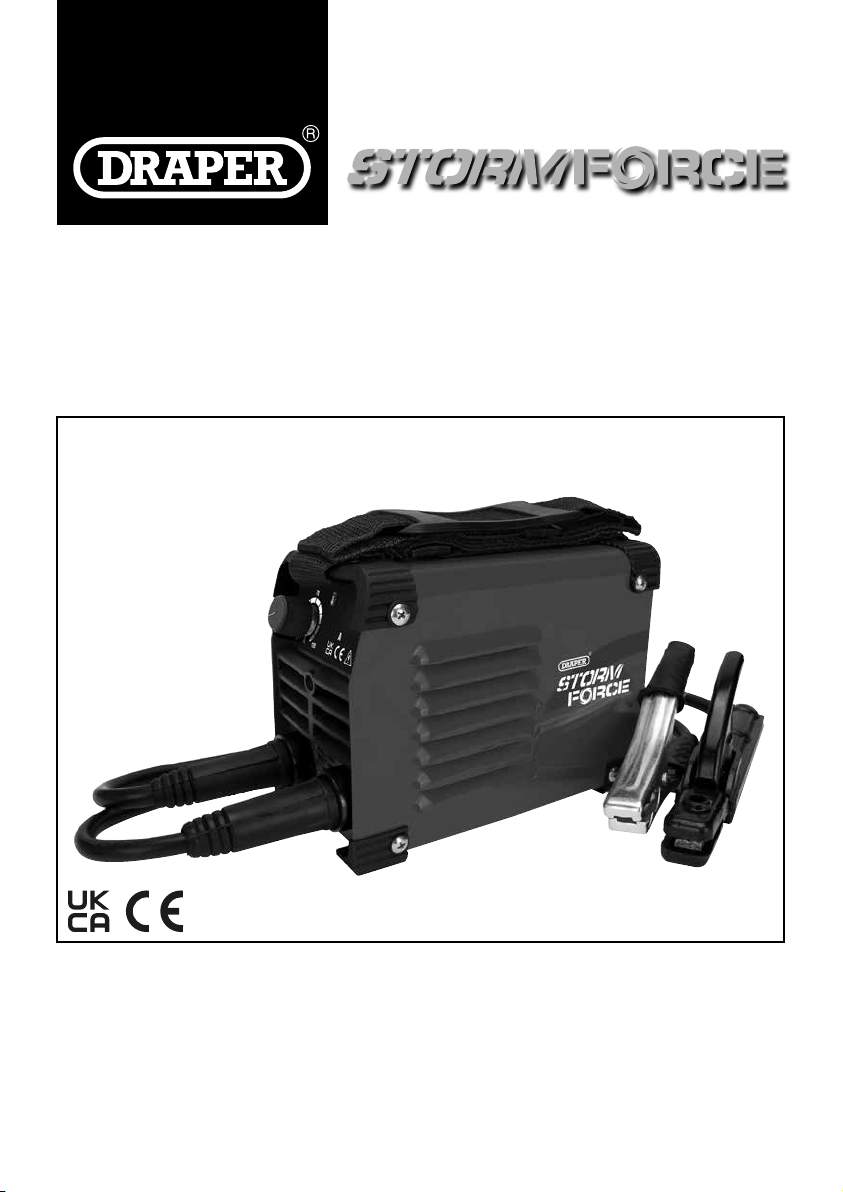
MMA IN VERT ER
WELDER
70041, 70042
These instructions accompanying the product are the original instructions. This document is part of the product,
keep it for the life of the product passing it on to any subsequent holder of the product. Read all these instructions
before assembling, operating or maintaining this product.
This manual has been compiled by Draper Tools describing the purpose for which the product has been designed,
and contains all the necessary information to ensure its correct and safe use. By following all the general safety
instructions contained in this manual, it will ensure both product and operator safety, together with longer life of the
product itself.
All photographs and drawings in this manual are supplied by Draper Tools to help illustrate the operation of the
product.
Whilst every effort has been made to ensure the accuracy of information contained in this manual, the Draper
Tools policy of continuous improvement determines the right to make modifications without prior warning.
Page 2
1. INTRODUCTION
1.1 SCOPE
This MMA welding machine is designed to weld ferrous
metals such as steel and iron.
This product is intended for domestic and infrequent
light trade use only.
Any application other than that it was intended for, is
considered misuse.
This product is not a toy and must not be used by
children or any person with reduced physical, sensory or
mental capabilities or lack of experience and knowledge,
or people unfamiliar with these instructions.
Local regulations may restrict the age of the operator.
1.2 UNDERSTANDING THIS MANUALS
SAFETY CONTENT:
Warning! – Information that draws attention to the
risk of injury or death.
Caution! – Information that draws attention to the risk of
damage to the product or surroundings.
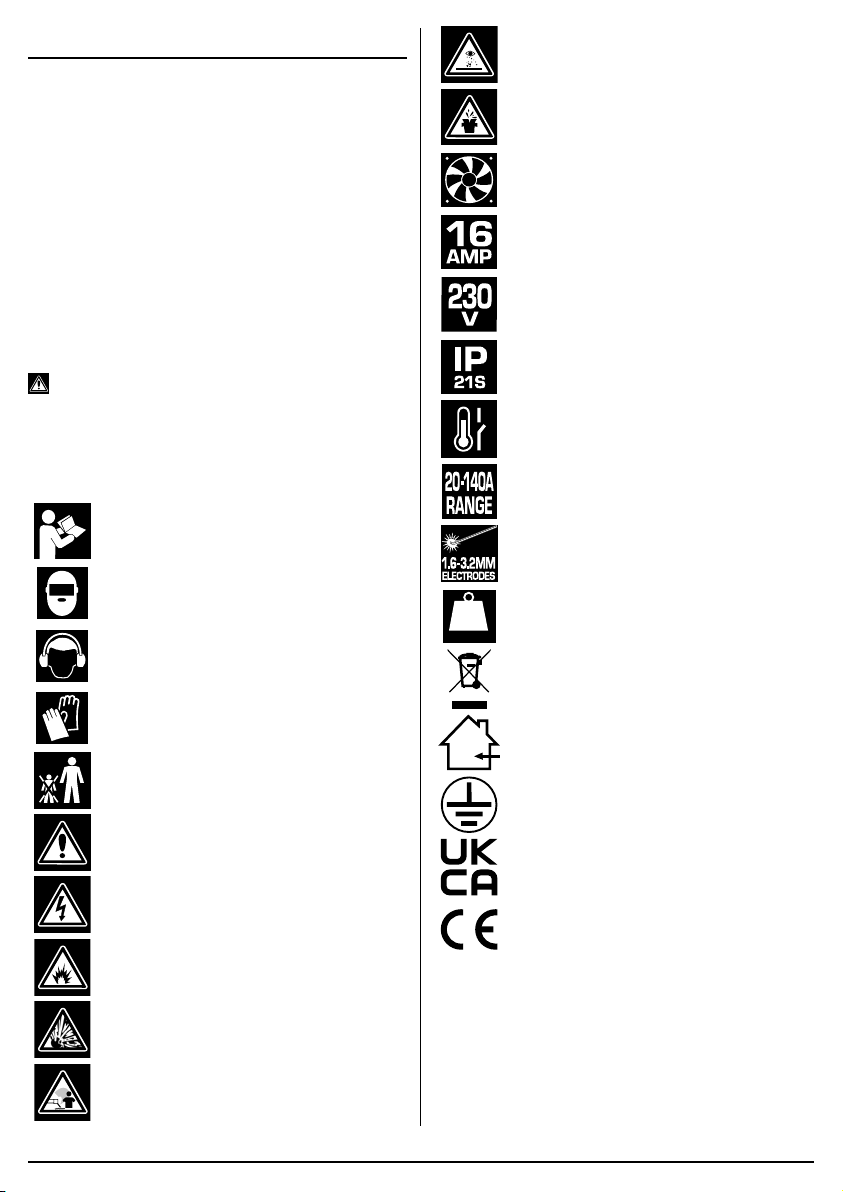
Danger of ultraviolet radiation.
Danger of burning splashes.
Fan cooled.
Input current.
Input voltage.
Protection rating.
Thermal overload.
1.3 EXPLANATION OF SYMBOLS
Warning!
Read the instruction manual.
Warning!
Wear suitable welding eye/face protection.
Warning!
Wear ear defenders (During grinding
operations).
Warning!
Wear protective gloves.
Keep out of the reach of children.
Warning!
Danger of electric shock.
Danger of fire.
Danger of explosion.
11.9
grossnet
MMA welding range.
Electrode size.
kg
Machine weight.
WEEE –
Waste Electrical & Electronic Equipment.
Do not dispose of Waste Electrical & Electronic
Equipment in with domestic rubbish.
For indoor use only.
Do not expose to rain.
Class 1 appliance
(Must be earthed).
UK Conformity Assessed.
European conformity.
Danger of fumes.
– 2 –– 3
Page 3
2. SPECIFICATION
2.1 SPECIFICATION
Stock No. .............................................................. 70041
Part No. ...................................................... INV140A/SF
Rated voltage .................................................. 230~50Hz
Input current .............................................................. 16A
Current range ...................................................20 – 140A
Electrode size ............................................... 1.6 – 3.2mm
Dinse Type Socket ..................................................25/10
Degree of protection .............................................. IP21S
Cooling ............................................................... Air (fan)
Insulation class .............................................................. F
Duty cycle: ...........................35% @ 140A / 100% @ 90A
Weight (Gross/Net/machine only) .............. 3.5/3.1/2.2kg
Stock No. .............................................................. 70042
Part No. ...................................................... INV120A/SF
Rated voltage .................................................. 230~50Hz
Input current .............................................................. 16A
Current range ...................................................20 – 120A
Electrode size ............................................... 1.6 – 3.2mm
Dinse Type Socket ..................................................25/10
Degree of protection .............................................. IP21S
Cooling ............................................................... Air (fan)
Insulation class .............................................................. F
Duty cycle: ...........................35% @ 120A / 100% @ 85A
Weight (Gross/Net/machine only) .............. 3.4/3.0/2.1kg
3. HEALTH AND SAFETY
INFORMATION
3.1 GENERAL SAFETY
INSTRUCTIONS
Warning! Read all safety warnings and all
instructions. When using electric tools basic safety
precautions should always be followed to reduce the risk
of fire, electric shock, and personal injury including the
following.
Read all these instructions before attempting to operate
this product and save these instructions.
Electric shock can kill:
– Remove the plug from the socket before carrying out
adjustment, servicing, or maintenance.
– Allow 5 minutes waiting time for the capacitors to
discharge before removing the panels for any
maintenance operations
– Do not touch live electrical parts.
– Never use electrode holders or cables with damaged
or deteriorated insulation.
– Keep the working environment, equipment, cables,
and clothing free from grease, oil, moisture, and dirt.
– Ensure the welding machine has been correctly
earthed and all panels are fitted securely.
– The operator must be insulated from the floor and
workbench using a dry insulation mat.
– Wear isolating footwear and gloves that are in good
condition, i.e. without holes.
– In hazardous conditions of increased electric shock
always ensure a second person is present in case of
an accident.
– Never change electrodes with bare hands or damp
gloves (for ARC/MMA welders).
– Keep welding cables away from power cables.
– Regularly inspect the condition of the welding, earth,
and power cables for signs of damage.
– Do not leave the machine unattended and remove
the plug from the socket when not in use.
– Do not use welding cables unsuitable for the
amperage.
– Ensure the earth clamp is adjacent to the weld seam,
secured to bare metal and when not in use is
insulated for safety.
– Keep all equipment well maintained.
– The operator shall prevent gas cylinders in the
vicinity of the workpiece from becoming part of the
welding circuit.
Fumes & Gases can be harmful:
– The welding process generates hazardous fumes as
a by-product. Inhalation of these fumes is hazardous
to health.
– Keep your head away from the weld to avoid
breathing the fumes.
– If welding in confined spaces ensure adequate
ventilation and use a fume extractor.
– Welding fumes displace oxygen. The danger of
suffocation.
– By-products of welding can react with other chemical
vapours to produce a toxic/explosive environment.
Welding can cause fire or explosion:
– Arc welding and allied processes can cause fire and
explosions and precautions shall be taken to
prevent these hazards.
– Before starting a weld ensure the area is clear of
flammable materials.
– Remove any inflammables to a safe distance,
especially substances likely to generate a dangerous
vapour.
– The welding arc can cause serious burns. Avoid
contact with skin.
–
Page 4

– Sparks and molten metal are cast out during
welding. Take precautions to prevent fire igniting and
wear protective clothing.
– Sparks and molten metal can pass through gaps. Be
aware that fire can start out of sight. Flammables in a
locked cabinet may not be safe.
– Do not weld pressurised containers.
– Do not weld tanks, drums, or other vessels until they
have been correctly cleaned/prepared for welding.
– Always have appropriate and fully maintained
fire-fighting equipment suitable for the materials used
and for use in electrical environments available in
close proximity at all times.
– Keep clothing free from oil and grease.
– Wear a hat, flame-proof apron, woollen clothing,
gloves, long sleeve tops with closed neck, trousers
(without turn-ups) to cover non-slip boots.
– Protective head and shoulder coverings should be
worn when overhead welding.
– Avoid taking any fuels with you e.g. cigarette lighters
or matches.
– Hot spots and their immediate surroundings should
be observed until their temperature has dropped to
normal.
Personal Protection:
– The body should be protected by suitable clothing.
– The use of neck protection may be necessary
against reflected radiation.
– Wear safety glasses when chipping, wire brushing,
grinding, or when near cooling welds as metal filings
or slag can be thrown up. Fully enclosed goggles are
advisable.
– Arc machines generate a magnetic field which is
detrimental to pacemaker recipients. Consult your
doctor before going near welding equipment/
operations.
– The UV and IR radiation generated by welding is
highly damaging to the eye, causing burns. This can
also affect the skin. Protect the eyes and face.
– The face and eyes shall be protected by suitable
welding shields equipped with appropriate ocular
protection filters.
– Where environments are subject to pedestrians and
traffic ensure a protective screen is used to avoid
accidental arc glare.
- Do not weld in the vicinity of children or animals and
ensure no one is looking before striking up.
– In the welding environment, damaging levels of noise
can exist. Wear hearing protection if the process
dictates.
– Do not touch hot equipment or metal. Allow the weld
time to cool, use the correct tool and wear protective
welding gauntlets.
– Wear flame retardant clothing (leather, wool, etc.).
– Take care when adjusting or maintaining the torch
that it has had time to cool sufficiently and is
disconnected.
– The arc generates
• ultra-violet radiation (can damage skin and eyes).
• visible light (can dazzle eyes and impair vision).
• infra-red (heat) radiation (can damage skin and
eyes).
– Such radiation can be direct or reflected from
surfaces such as bright metals and light coloured
objects.
Gas cylinders:
– Gas cylinders should be located or secured so that
they cannot be knocked over.
– Shield gas containers can explode if damaged. Take
care when handling.
– Ensure gas cylinders are shut-off when not in use
and between operations.
– Take care that no build-up of gas is permitted to form
in confined areas.
– Cylinders must be in an upright position at all times
during use and storage.
– The gas cylinder must never come in contact with
the electrode.
– Follow the manufacturer’s instructions for handling,
storing, and using the gas bottle correctly and safely.
– Use the correct equipment to connect the gas bottle
to the welding torch.
Limitations:
– Do not use for:
• operations in severe conditions (e.g. extreme
climates, freezer applications, strong magnetic
fields, etc).
• operations subject to special rules (e.g.
potentially explosive atmospheres, mines, etc).
• operations that require ingress protection greater
than IPX0, e.g. in rain or snow, etc.
General:
– Training should be sought out in
• the safe use of this equipment;
• the processes;
• the emergency procedures;
– Welding power sources are not to be used for pipe
thawing.
– Take precautions against toppling over, if the power
source shall be placed on a tilted plane.
– All equipment should be kept in good working
condition, inspected and, when defective, promptly
repaired or withdrawn from service - All equipment
should be placed so that it does not present a
hazard in passageways, on ladders, or stairways,
and should be operated in accordance with the
manufacturer’s instructions.
– 4 –
Page 5
– In the vicinity of an arc, non-reflective curtains or
screens shall be used to isolate persons from
radiation. A warning, e.g. a symbol for eye
protection, should refer to the hazard of arc
radiation.
the arc
4. UNPACKING AND
CHECKING
4.1 PACKAGING
Carefully remove the product from the packaging and
examine it for any sign of damage. Check contents
against the parts shown in Fig A. If any part is damaged
5. TECHNICAL DESCRIPTION
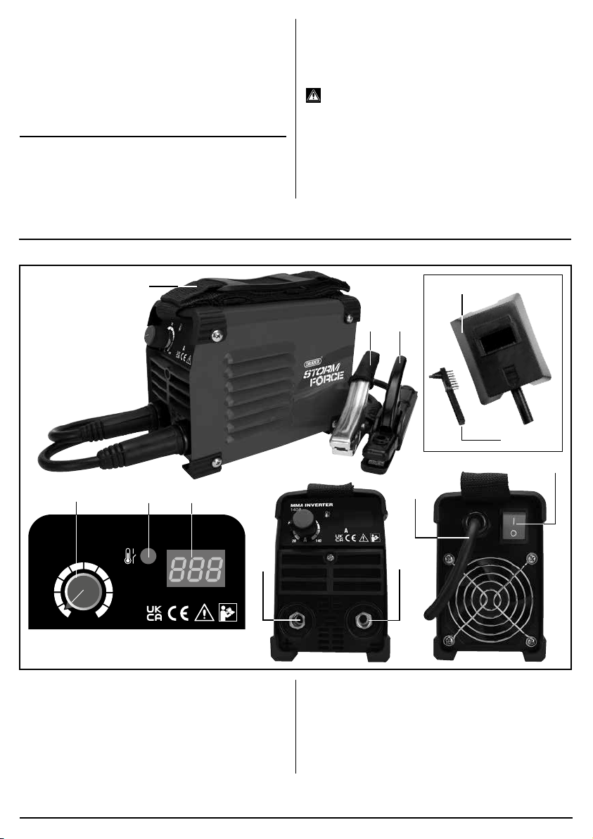
5.1 PRODUCT IDENTIFICATION – FIG.A
or missing, please contact the Draper Help Line (see
back page). Do not attempt to use the product!
The packaging material should be retained during the
warranty period, in case the product needs to be
returned for repair.
Warning!
• Some of the packaging materials may be harmful to
children. Do not leave any of these materials in
reach of children.
• If any of the packaging is to be thrown away, make
sure they are disposed of correctly, according to local
regulations.
(1)
MMA INVERTER
140A
80
(4)
(2) (3)
(7)
(5) (6)
(10)
(8)
(11)
A
A
20
70041 shown.
(1) Current adjustment control.
(2)
Thermal overload LED indicator.
(3) LED amperage display.
(4) Carry handle.
(5) MMA earth clamp.
(6) MMA welding electrode holder.
Note: For details of our full range of accessories and consumables, please visit drapertools.com
140
(7) MMA electrode holder connection.
(8) MMA earth clamp connection.
(9) ON/OFF Switch.
(10) Power supply cable.
(11) Face mask.
(12) Brush.
– 5 –
(12)
(9)
FIG.A
Page 6
6. ASSEMBLING THE
MMA WELDER
6.1 CONNECTION TO THE POWER
SUPPLY
Make sure the power supply information on the product’s
rating plate is compatible with the power supply you
intend to connect it to.
A suitable plug must be fitted by a qualified
electrician.
This product’s wiring has insulation stripped in
preparation for wiring a 16A plug (not supplied).
It is designed for connection to a 16 amp power supply
rated at 230V AC.
Because it is constructed mostly of metal parts, it is a
Class 1 machine; meaning, it must have an earth
connection in the power supply. This is to prevent
electrocution in the event of a failure.
Note: Remove the plug from the socket before carrying
out adjustment, servicing or maintenance.
Check that the electrical supply delivers the voltage and
frequency corresponding to the product and that it is
fitted with a delayed fuse suited to the maximum
delivered rated current.
Note: This product has been set to the highest voltage
at the factory.
6.2 CONNECTING THE EARTH
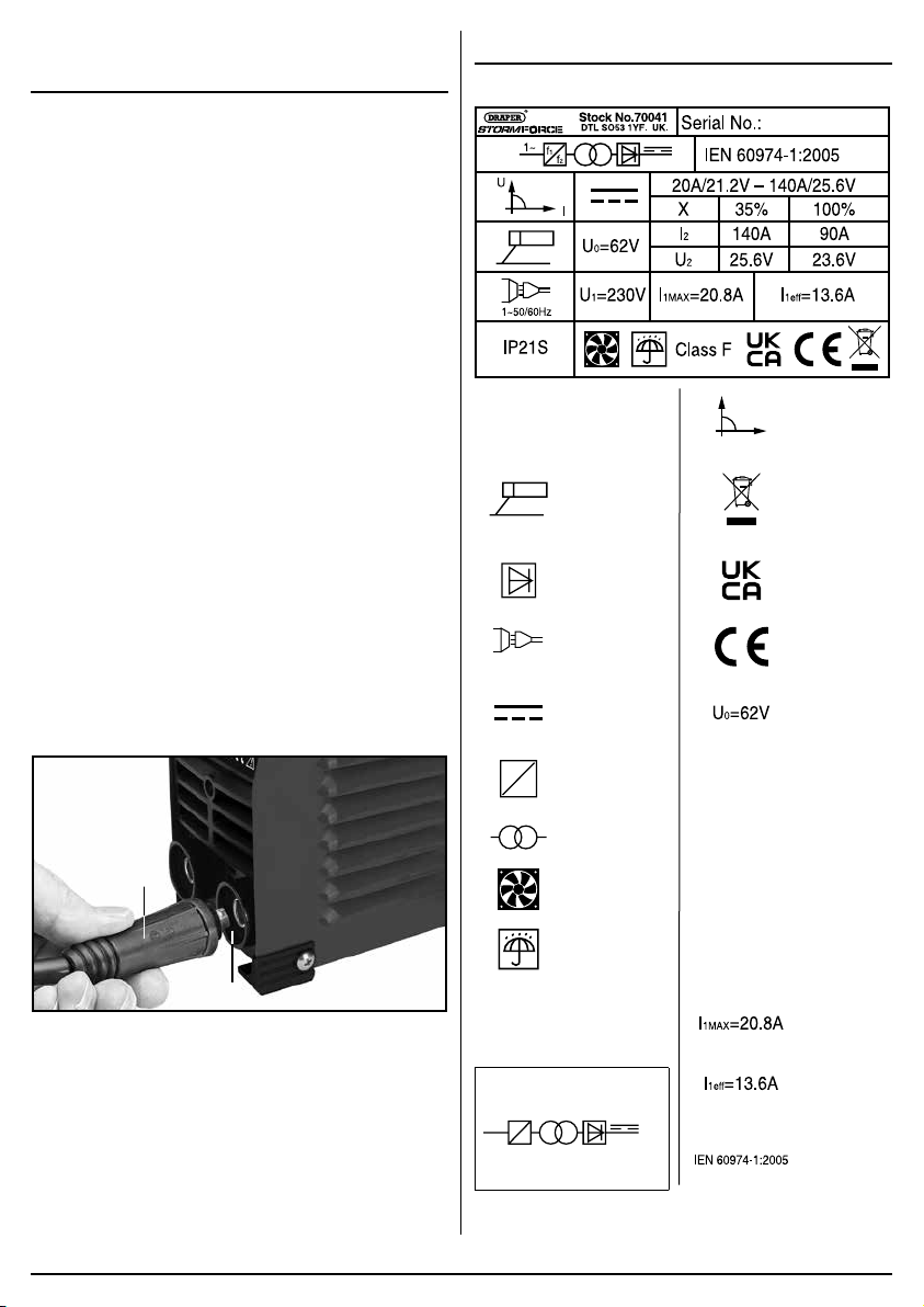
CLAMP – FIG.1
− With the lug on the pin at top, push the connector
(5.1) fully into the right-hand (–) port (8) then turned
clockwise 180° to lock, hand tight only.
(5.1)
(8)
FIG.
1
6.3 ATTACHING THE ELECTRODE
HOLDER
− The electrode holder (6) is connected into the left
hand (+) (7) port unit in the same way as the earth
clamp.
7. SETTING THE MMA WELDER
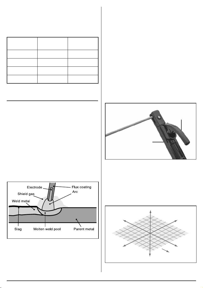
7.1 RATING PLATE
Unit’s
1
f
1
f
f
2
2
protection class
rating.
MMA welder.
Semiconductor
diode rectifier.
Power supply
identifier, e.g.
socket with 3
poles.
Direct Current
(DC) delivery.
Inverter
frequency
conversion
†
stage.
Transformer.
Fan cooled.
Indoor use
only. Do not
expose to rain.
Insulation
rating.
IP21S
1~50/60Hz
f
Class F
†
Symbols can be combined,
for example:
1~
Single Phase D.C MMA
Welder.
* Waste Electrical & Electronic Equipment
U
†
†
U1=230V
†
U
X
2
I
2
(8.1)
Constant
current.
I
Do not
dispose of
WEEE* as
unsorted
municipal
waste.
UK Conformity
Assessed.
European
conformity.
Secondary
no-load
voltage.
Rated supply
voltage.
Rated duty
cycle.
Welding
current
(AMPS)
Welding
current
(VOLTS)
Unit’s
maximum
absorbed
current
(AMPS).
Unit’s effective
absorbed
current (AMPS).
European
reference safety
standard.
(8)
– 6 –
Page 7
7.2 MMA/ARC WELDING FILLER ROD
(ELECTRODE) SELECTION – FIG.2
The correct selection of electrode size and type will vary
for each application dependent upon material thickness,
material type, amperage and equipment, however as a
guide the figures below provide an indication.
MMA Electrode Material
≤1.6mm 1-1.5mm ≤50A
2.0mm 1.2-3mm 45 - 75A
2.5mm 2-5mm 75 - 110A
3.25mm 4-8mm 100 - 150A
FIG.
2
Thickness
Amp Range
8. OPERATION
8.1 BASIC MMA/ARC WELDING
PROCESS OVERVIEW – FIG.3
During the MMA welding process, the arc created
between the work piece and the consumable electrode
rod melts the parent metal and the filler metal in a weld
pool.
The electrode’s flux coating reacts during this process
and develops into a shield gas protecting the weld bead.
Part of this reaction leaves a trail of slag which solidifies
behind the weld pool protecting the weld as it cools.
The most common varieties of electrodes are cellulosic,
rutile and basic, the latter two being the most general
purpose.
Selection of the appropriate specification electrode is
important to achieve a good quality weld. Seek guidance
if unsure of selection.
− With the earth clamp and electrode holder
connected, connect the machine to the power supply.
The power display will illuminate as confirmation. Set
the amperage appropriate to the selected electrode
size.
− Secure the earth clamp to a clean sound section of
the parent metal in the vicinity to the intended weld.
− With all safety equipment in place and personal
protective clothing on begin welding.
− Lower the electrode down toward the parent metal
and strike the arc.
− The position of the electrode is critical to the arc and
the end result.
− Achieving a good weld will take practice. For more
detailed information refer to a industry standard
welding publication and/or seek training on the
subject.
− Use of an anti-spatter spray – Draper stock
No.05709 – will help to achieve a cleaner finished
weld.
(6.1)
(6)
FIG.
4
8.3 DIRECTION OF WELD – FIG.5
− Strike the initial arc perpendicular to the parent metal
before moving the electrode holder in the direction of
travel 20-30° (Z,Y axis) and tilt it 20-30° (Z,X axis).
− Maintain a constant gap between the electrode tip
and the weld pool of approximately 1 – 1.5 × the
diameter of the electrode for a stable arc.
FIG.
3
8.2 MMA/ARC MACHINE OPERATION
– FIG.4
− Prepare the joint(s) to be welded.
− Insert the electrode suitable for the application into
the electrode holder (6) while pressing lever (6.1).
– 7 –
FIG.
Z
-X-Y
XY
Direction
-Z
5
of weld
Page 8
8.4 ‘HOT START’ FEATURE
The machine is equipped with a ‘Hot Start’ feature.
− A peak of current is delivered when striking the arc.
This gives easy starting the electrodes, especially
when faced with challenging operating conditions, ie;
damp, or ‘difficult to run’ electrodes or an imperfect
workpiece.
8.5 ‘ANTI-STICK’ FEATURE
The machine is equipped with an ‘Anti-Stick’ feature,
which ensures smooth welding and reduces instances of
the electrode becoming stuck to the parent metal.
− The machine will automatically reduce the intensity
of the current in order to aid quick and simple
separation of the electrode and parent metal.
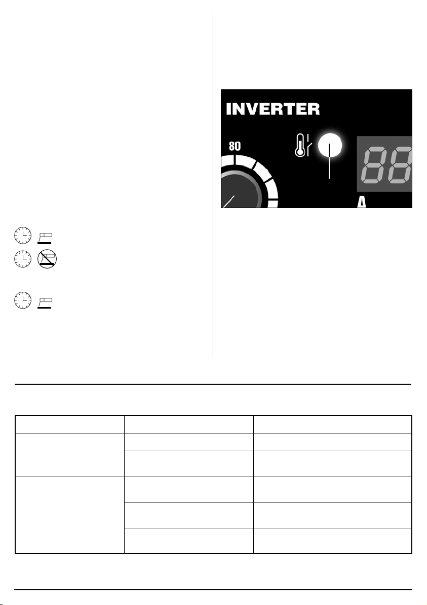
8.7 THERMAL CUT-OUT – FIG.6
If welding for extended periods, the thermal cut-out will
activate and the LED indicator (2) will illuminate,
prohibiting use of the machine until sufficiently cool.
Caution! After completion of any welding task, leave the
unit connected to the power supply for a sufficient period
to allow the cooling fan to continue working.
8.6 DUTY CYCLE
Duty Cycle is a percentage of 10 mins, in which a
machine can operate at a rated load without overheating
and interruption from the thermal cut-out device.
Example: 150A @ 30% Duty factor
Example: 95A @ 100% Duty factor
95A continuous welding
To increase the operation time, reduce the amperage.
Note: The heating tests have been carried out at
ambient temperature and the duty cycle (duty factor) at
20°C has been determined by simulation.
150A welding for 3 minutes
7 minutes down time
FIG.
6
(2)
9. MAINTENANCE AND TROUBLESHOOTING
9.1 TROUBLESHOOTING GUIDE
WARNING: For your own safety, turn the switch off and remove the plug from the power supply socket.
Problem Possible cause Required action
No spark. Bad clamp connection. Check clamp connection.
PCB on the inver ter is defective
or damaged.
Contact Draper Tools/authorised service
agent for repair/replacement.
No output voltage. Overheated unit – the thermal
cut-out LED will be illuminated.
Failure of internal relay. Contact Draper Tools/authorised service
PCB on the inver ter is defective
or damaged.
– 8 –
Wait for unit to cool and the re-setting of
the thermal cutout.
agent for repair/replacement.
Contact Draper Tools/authorised service
agent for repair/replacement.
Page 9
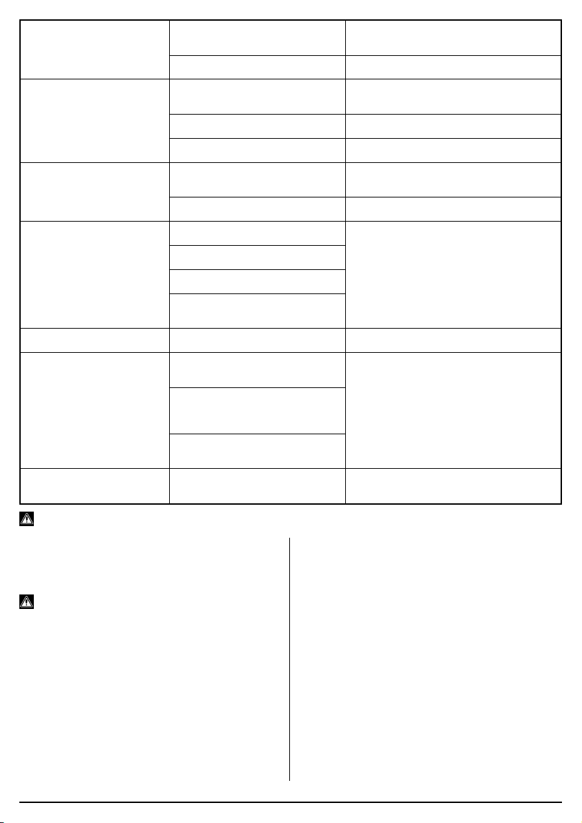
Incorrect current output. Current control selector is
defective.
Supply voltage is low power. Check the mains power distribution.
Contact Draper Tools/authorised service
agent for repair/replacement.
Porous welded joint. Acid electrode on steel with high
sulphur content.
Workpieces are too far apart. Move welded edges closer together.
Workpiece is too cold. Move slowly at begining of weld.
Cracks in weld. Material is contaminated with
dirt, oil, rust.
Insuficient current. Enable sufficient current.
Limited penetration. Low current.
High welding rate.
Reversed polartity.
Electrode non-aligned to
position of movement.
High sprays. Electrode is too inclined. Make the appropriate corrections.
Welding profile defects. Welding parameters are
incorrect.
Pass rate is not related
to operating parameter
requirements.
Electrode not inclined during
welding session.
Unstable arc. Insufficient current. Check ear th connection and electrode
Use a basic electrode.
Clean workpiece before welding
commences (essential for neat beads).
Make the appropriate corrections.
Follow rudimentary welding processes
and procedures.
conditions.
Warning! Please note, all repairs/service should be carried out by a qualified person.
9.2 MAINTENANCE
Regular inspection and cleaning reduces the necessity
for maintenance operations and will keep your tool in
good working condition.
Warning! Remove the plug from the power supply.
Periodically the welder must be checked as detailed
below.
− Check the electrode and earth cable connections.
− Clean the outside of the welder with a damp cloth.
− Occasionally test to ensure the thermal cut-out
device is operating correctly, i.e. weld for an
extended period or on a maximum duty cycle.
− Check the condition of the warning labels.
− Replace any worn parts.
− If the replacement of the supply cord is necessary,
this has to be done by Draper Tools or an authorised
service agent to avoid a safety hazard.
The welder must be correctly ventilated during tool
operation. Avoid blocking the air inlets and vacuum the
ventilation slots regularly.
Do not use solvents or fuels to clean the product. When
not in use, store the product in a safe, dry place.
– 9 –
Page 10
10. WARRANTY
11. DISPOSAL
10.1 WARRANTY
Draper tools have been carefully tested and inspected
before shipment and are guaranteed to be free from
defective materials and workmanship.
Should the tool develop a fault, please return the
complete tool to your nearest distributor or contact:
Draper Tools Limited, Chandler’s Ford, Eastleigh,
Hampshire, SO53 1YF. England.
Telephone Sales Desk: +44 (0)23 8049 4333 or:
Product Helpline +44 (0)23 8049 4344.
A proof of purchase must be provided.
If upon inspection it is found that the fault occurring is
due to defective materials or workmanship, repairs will
be carried out free of charge. This warranty period
covering labour is 12 months from the date of purchase
except where tools are hired out when the warranty
period is 90 days from the date of purchase. This
warranty does not apply to any consumable parts, any
type of battery or normal wear and tear, nor does it
cover any damage caused by misuse, careless or
unsafe handling, alterations, accidents, or repairs
attempted or made by any personnel other than the
authorised Draper warranty repair agent.
Note: If the tool is found not to be within the terms of
warranty, repairs and carriage charges will be quoted
and made accordingly.
This warranty applies in lieu of any other warranty
expressed or implied and variations of its terms are not
authorised.
Your Draper warranty is not effective unless you can
produce upon request a dated receipt or invoice to verify
your proof of purchase within the warranty period.
Please note that this warranty is an additional benefit
and does not affect your statutory rights.
Draper Tools Limited.
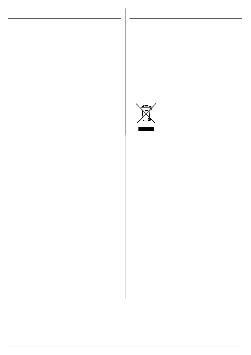
11.1 DISPOSAL
– At the end of the machine’s working life, or when it
can no longer be repaired, ensure that it is disposed
of according to national regulations.
– Contact your local authority for details of collection
schemes in your area.
In all circumstances:
• Do not dispose of power tools with
domestic waste.
• Do not incinerate.
• Do not dispose of WEEE* as unsorted
municipal waste.
* Waste Electrical & Electronic Equipment.
– 10 –
Page 11

NOTES
– 11 –
Page 12

 Loading...