

Page 1

HYDRAULIC
MOTORCYCLE
& ATV LIFT
37777
These instructions accompanying the product are the original instructions. This document is part of the product, keep
it for the life of the product passing it on to any subsequent holder of the product. Read all these instructions before
assembling, operating or maintaining this product.
This manual has been compiled by Draper Tools describing the purpose for which the product has been designed,
and contains all the necessary information to ensure its correct and safe use. By following all the general safety
instructions contained in this manual, it will ensure both product and operator safety, together with longer life of the
product itself.
All photographs and drawings in this manual are supplied by Draper Tools to help illustrate the operation of the
product.
Whilst every effort has been made to ensure the accuracy of information contained in this manual, the Draper Tools
policy of continuous improvement determines the right to make modifications without prior warning.
Page 2

1. TITLE PAGE
1.1 INTRODUCTION:
USER MANUAL FOR: Hydraulic Motorcycle & ATV Lift
Stock No: 37777
Part No: MC/ATV2B
1.2 REVISIONS:
Date first published September 2021.
As our user manuals are continually updated, users should make
sure that they use the very latest version.
Downloads are available from: http://drapertools.com/manuals
Draper Tools Limited Draper Tools Limited
Hursley Road Oude Graaf 8
Chandler’s Ford 6002 NL
Eastleigh WEERT
Hampshire Netherlands
SO53 1YF
UK
Website: drapertools.com
Product Help Line: +44 (0) 23 8049 4344
General Fax: +44 (0) 23 8026 0784
1.3 UNDERSTANDING THIS MANUALS SAFETY CONTENT:
Warning! – Information that draws attention to the risk of injury or death.
Important – Information that draws attention to the risk of damage to the product or surroundings.
1.4 COPYRIGHT © NOTICE:
Copyright © Draper Tools Limited.
Permission is granted to reproduce this publication for personal and educational use only.
Commercial copying, redistribution, hiring or lending is prohibited.
No part of this publication may be stored in a retrieval system or transmitted in any other form or
means without written permission from Draper Tools Limited.
In all cases this copyright notice must remain intact.
– 2 –
Page 3

2. CONTENTS
2.1 TABLE OF CONTENTS
1. TITLE PAGE
1.1 INTRODUCTION .......................................................................................................... 2
1.2 REVISIONS .................................................................................................................. 2
1.3 UNDERSTANDING THIS MANUALS SAFETY CONTENT ......................................... 2
1.4 COPYRIGHT © NOTICE .............................................................................................. 2
2. CONTENTS
2.1 TABLE OF CONTENTS ...............................................................................................3
3. WARRANTY
3.1 WARRANTY ................................................................................................................. 4
4. INTRODUCTION
4.1 SCOPE ......................................................................................................................... 5
4.2 SPECIFICATION .......................................................................................................... 5
4.3 HANDLING AND STORAGE ........................................................................................5
5. HEALTH AND SAFETY INFORMATION
5.1 GENERAL SAFETY INSTRUCTIONS ......................................................................... 6
5.2 RESIDUAL RISK .......................................................................................................... 6
6. TECHNICAL DESCRIPTION
6.1 IDENTIFICATION ......................................................................................................... 7
7. UNPACKING AND CHECKING
7.1 PACKAGING ................................................................................................................ 8
. ASSEMBLY & PREPARATION
8
8.1 FITTING THE HYDRAULIC UNIT & FOOT PEDAL ..................................................... 9
8.2 BLEEDING THE HYDRAULIC SYSTEM ..................................................................... 9
. OPERATION & USE
9
9.1 GENERAL OPERATIONAL PROCEDURE ................................................................ 10
10. MAINTENANCE
10.1 MAINTENANCE ......................................................................................................... 11
11. DISPOSAL
11.1 DISPOSAL ................................................................................................................. 12
12. EXPLANATION OF SYMBOLS
12.1 EXPLANATION OF SYMBOLS .................................................................................. 13
– 3 –
Page 4

3. WARRANTY
3.1 WARRANTY
Draper tools have been carefully tested and inspected before shipment and are guaranteed to be
free from defective materials and workmanship.
Should the tool develop a fault, please return the complete tool to your nearest distributor or
contact:
Draper Tools Limited, Chandler’s Ford, Eastleigh, Hampshire, SO53 1YF. England.
Telephone Sales Desk: +44 (0) 8049 4333 or Product Help Line +44 (0) 23 8049 4344.
A proof of purchase must be provided with the tool.
If upon inspection it is found that the fault occurring is due to defective materials or workmanship,
repairs will be carried out free of charge. This warranty period covering parts/labour is 12 months
from the date of purchase except where tools are hired out when the warranty period is 90 days
from the date of purchase. This warranty does not apply to any consumable parts, any type of
battery or normal wear and tear, nor does it cover any damage caused by misuse, careless or
unsafe handling, alterations, accidents, or repairs attempted or made by any personnel other than
the authorised Draper warranty repair agent.
Note: If the tool is found not to be within the terms of warranty, repairs and carriage charges will
be quoted and made accordingly.
This warranty applies in lieu of any other warranty expressed or implied and variations of its terms
are not authorised.
Your Draper warranty is not effective unless you can produce upon request a dated receipt or
invoice to verify your proof of purchase within the warranty period.
Please note that this warranty is an additional benefit and does not affect your statutory rights.
Draper Tools Limited.
– 4 –
Page 5

4. INTRODUCTION
4.1 SCOPE
Foot operated lever style hydraulic lifting mechanism. Rubber support arms to help prevent
damage, suitable for lifting bikes, quads and all terrain vehicles.
This product is suitable for enthusiasts and tradespersons alike. Any application other than that it
was intended for is considered misuse.
4.2 SPECIFICATION
Stock No. ................................................................................................................................. 37777
Part No. ........................................................................................................................... MC/ATV2B
Safe working load ..................................................................................................................... 680kg
Minimum height ...................................................................................................................... 120mm
Maximum height ..................................................................................................................... 380mm
Platform size ................................................................................................................. 335 × 330mm
Base size ...................................................................................................................... 810 × 370mm
Lift Height ............................................................................................................................... 260mm
Platform mat thickness ............................................................................................................... 3mm
Platform mat size ............................................................................................................ 55 × 335mm
Platform frame thickness ............................................................................................................ 3mm
Lifting arms thickness .............................................................................................................. 2.5mm
Base frame thickness .............................................................................................................. 3.8mm
4.3 HANDLING AND STORAGE
− Care must be taken when handling this product.
• This product is not a toy and must be respected.
− Environmental conditions can have a detrimental effect on this product if neglected.
• Exposure to damp air can gradually corrode components.
• If not cleaned and maintained correctly or regularly, the machine will not perform at its best.
– 5 –
Page 6

5. HEALTH AND SAFETY INFORMATION
5.1 GENERAL SAFETY INSTRUCTIONS
Warning! Before use, ensure that the motorcycle to be supported has a suitable structure and
centre of gravity to accommodate the platform without damaging the motorcycle. DO NOT use if
the stand will foul on the exhaust or other vulnerable parts.
− Locate the stand in a suitable work area. Keep area clean and tidy and free from unrelated
materials and ensure that there is adequate lighting. Also ensure that the floor is level and
strong enough (preferably concrete) to take the weight of the stand and the bike. DO NOT
operate the stand on tarmacadam, as the surface may be unstable.
− Keep the stand clean for best and safest performance.
− The maximum bike weight is 680kg. DO NOT exceed this rated capacity.
− Before lifting check that there are no overhead obstructions.
− Keep children and unauthorised persons away from the work area.
− DO NOT use the stand for a task it is not designed to perform.
− DO NOT operate the stand if damaged.
− DO NOT exceed the rated capacity of the stand.
− DO NOT allow untrained persons to operate the stand.
− DO NOT make any modifications to the stand.
− Before lowering the stand ensure that there are no obstructions underneath the motorcycle and
that all persons are standing clear.
− Before storing, ensure that all parts are clean and free of grease and oil and the stand is fully
lowered. Store stand in a safe area.
Warning! The instructions referred to in this manual are unable to cover all possible situations that
may occur. It must be understood that common sense and caution are factors which are unable to
build into this product, but must be applied by the operator.
5.2 RESIDUAL RISK
Important: Although the safety instructions and operating manuals for our tools contain extensive
instructions of safe working with lifting equipment, every machine involves a certain residual risk
which can not be completely excluded by safety mechanisms. Lifting equipment must therefore
always be operated with caution!
– 6 –
Page 7
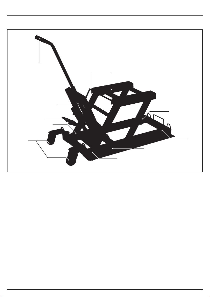
6. TECHNICAL DESCRIPTION
6.1 IDENTIFICATION
(2)
(7)(4)
(6)
(1)
(8)
(5)
(3)
(1) Lift foot pedal.
(2) Handle.
(3) Castor wheels.
(4) Safety bar.
(5) Fixed wheels.
(5)
(10)
(9)
(6) Hydraulic ram unit.
(7) Lift base.
(8) Lower foot pedal.
(9) Rear support feet.
(10) Safety lock mechanism.
– 7 –
Page 8

7. UNPACKING AND CHECKING
7.1 PACKAGING
Carefully remove the product from the packaging and examine it for any sign of damage that may
have happened during shipping. Lay the contents out and check them against the parts shown
below. If any part is damaged or missing, please contact the Draper Help Line (the telephone
number appears on the Title page) and do not attempt to use the product.
The packaging material should be retained at least during the warranty period, in case the
machine needs to be returned for repair.
Warning!
− Some of the packaging materials used may be harmful to children. Do not leave any of these
materials in the reach of children.
− If any of the packaging is to be thrown away, make sure they are disposed of correctly,
according to local regulations.
– 8 –
Page 9
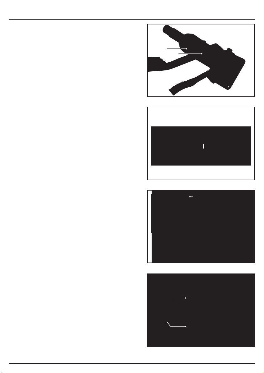
8. ASSEMBLY & PREPARATION
8.1 FITTING THE HYDRAULIC UNIT &
FOOT PEDAL – FIGS.1 – 3
− Attach the hydraulic ram unit (6) to the lift base
using the fixings provided. Noting that the unit
will only attach in one orientation (FIG.4).
− Attach the handle (2)to the lift frame using
fixing supplied.
− Locate the lift foot pedal (1) into the socket of
the hydraulic ram unit (6.1)and secure using
screw and washer (1.1).
− Tighten the ram bolt, attach the remaining end
of the foot pedal.
− Extend the hydraulic ram unit, using the foot
pedal (1)and lift the frame to allow the main
pivot bolt (6.2) to be attached to the frame.
− Attach the rear castor wheels (3)to the frame.
− Check tightness of all fixings.
8.2 BLEEDING THE HYDRAULIC
SYSTEM – FIG.4
Before use the hydraulic system must be bled to
ensure safe operation.
− To bleed the system:
• Pump the lift foot pedal (1) until the unit is at
its maximum height.
• While depressing the lower foot pedal (8),
fully pump and release the lift foot pedal at
least 10 full strokes.
• This will purge the valve system of any air.
FIG.
FIG.
(6)
1
2
(6.1)
(1)
(1.1)
(2)
– 9 –
FIG.
FIG.
(6.2)
3
(1)
(8)
4
Page 10

9. OPERATION & USE
9.1 GENERAL OPERATIONAL
PROCEDURE – FIG.5
Warning! Before use, ensure you read,
understand and apply the safety instructions
before use.
Before use, ensure that the motorcycle has a
suitable structure and centre of gravity to
accommodate the stand without damaging the bike.
− DO NOT use the stand if it will foul on the
exhaust, fairing or other vulnerable parts. If
necessary remove any lower fairing and
ensure that the bike is stable on the stand
before operating.
− Before lifting, ensure that there is nothing above
the motorcycle that could be damaged by using
the lift.
− Position the bike in a suitable area, checking that
the surface on which the stand will be placed is
solid and flat (preferably concrete).
− Ensure there is good access and clearance
beneath the bike for the stand.
− Inspect the underside of the motorcycle for
suitable support points, bearing in mind the
centre of gravity of the motorcycle and which
wheel is to be lifted from the ground.
− Place the stand under the motorcycle in the
approximate position required.
− Pump the lift foot pedal to raise the stand until the platform is just in contact with the underside
of the motorcycle. Adjust the position of the stand as necessary and before lifting begins, use
rear support feet to level stand and ensure load is taken away from rear castor wheels, and
that the stand is fully immobilised. Only when stand is unable to move on the wheels can lifting
begin.
− Pump lift foot pedal to lift motorcycle to required height, ensuring that safety lock mechanism is
operating.
− While working on motorcycle ensure that it will remain stable and that the centre of gravity will
not be affected by removing major/heavy components (wheels, engines etc.).
− Warning! DO NOT move the lift while loaded as serious damage, personal injury or
death may be caused. This unit IS NOT designed to transport or move items – It is a lift
ONLY.
− When work is complete, check under the stand to ensure that there are no obstructions and
that it is safe to lower the unit, depress lower foot pedal gently to lower the stand.
− When the stand is fully lowered, ensure that the bike is standing on its wheels and is
supported in the upright position – BEFORE removing the lift.
5 FIG.
– 10 –
Page 11

10. MAINTENANCE
10.1 MAINTENANCE
− When the stand is not in use, store it in the lowered position.
− Keep the stand clean and wipe off any oil or grease. Lubricate all moving parts with oil.
− Before each use check all parts. If any part of the stand is damaged or defective, remove the
stand from service and take the necessary action to remedy the problem. DO NOT use the
stand if it is believed to have been subjected to abnormal load or shock. Inspect and take
appropriate action.
– 11 –
Page 12

11. DISPOSAL
11.1 DISPOSAL
– At the end of the machine’s working life, or when it can no longer be repaired, ensure that it is
disposed of according to national regulations.
– Contact your local authority for details of collection schemes in your area.
In all circumstances:
• Do not dispose of this product with domestic waste.
• Do not incinerate.
• Do not abandon in the environment.
– 12 –
Page 13
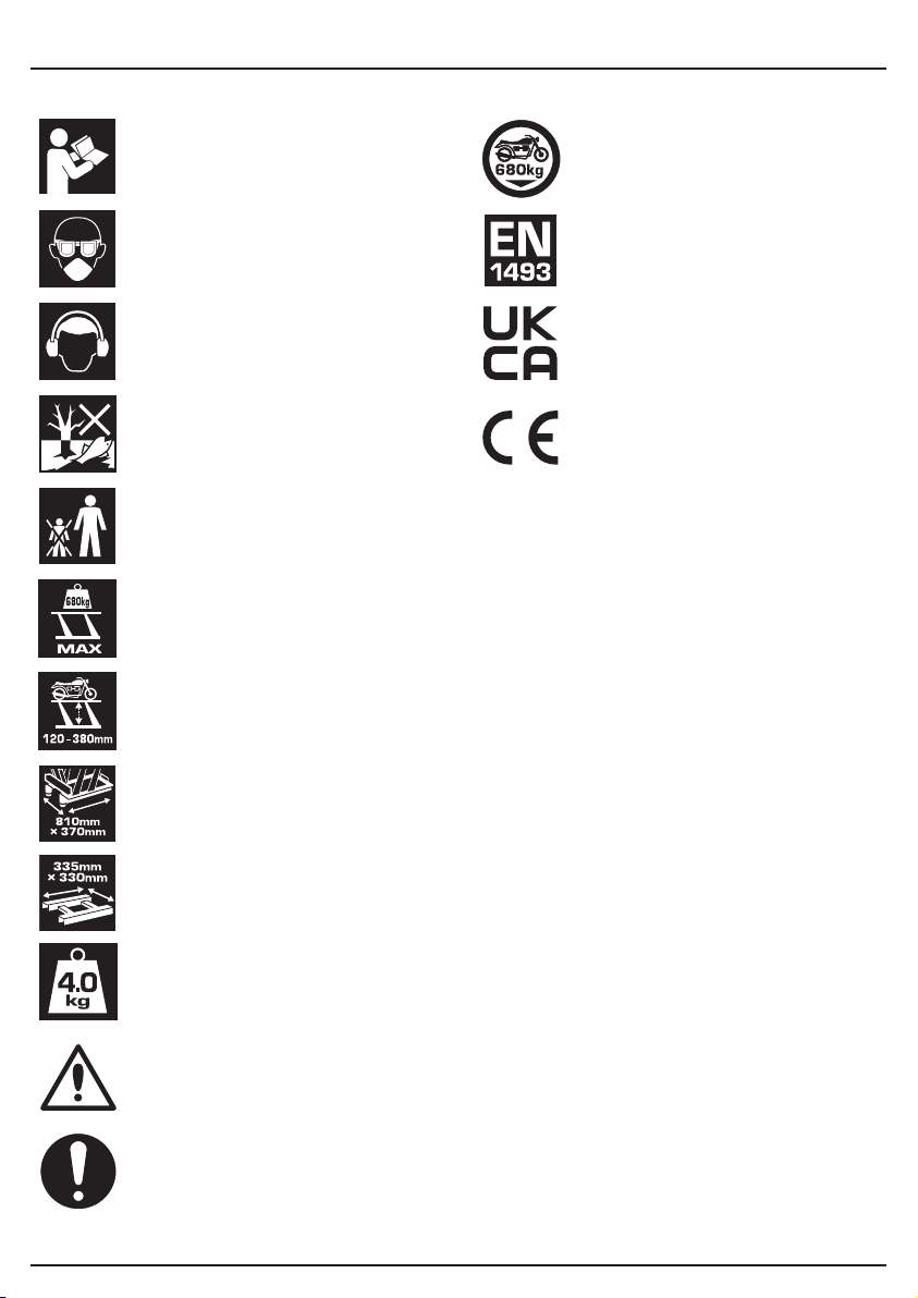
12. EXPLANATION OF SYMBOLS
12.1 EXPLANATION OF SYMBOLS
Read the instruction manual.
Wear face mask and safety
glasses.
Wear ear defenders.
Do not abandon into the
environment.
Keep out of the reach of children.
Maximum safe working load.
Minimum and maximum lifting
height range.
Maximum safe working load.
European safety standards
conformity.
UK Conformity Assessed.
European conformity.
Base dimensions
Pad dimensions
Net product weight
(example shown).
Warning!
Mandatory action required.
– 13 –
Page 14

NOTES
– 14 –
Page 15

NOTES
– 15 –
Page 16

CONTACTS
Draper Tools Limited
UK: Hursley Road, Chandler’s Ford, Eastleigh,
Hampshire. SO53 1YF. U.K.
EU: Oude Graaf 8
6002 NL Weert (NL)
Help Line: (023) 8049 4344
Sales Desk: (023) 8049 4333
Internet: drapertools.com
E-mail: [email protected]
General Enquiries: (023) 8026 6355
Service/Warranty Repair Agent:
For aftersales servicing or warranty repairs, please contact the
Draper Tools Help Line for details of an agent in your local area.
YOUR DRAPER STOCKIST
MCCH0921
©Published by Draper Tools Limited.
No part of this publication may be reproduced, stored in a retrieval system or transmitted in any form or by any means,
electronic, mechanical photocopying, recording or otherwise without prior permission in writing from Draper Tools Ltd.
 Loading...