

Dranetz Technologies DXPT-S-H100APKG-US, DXPT-S-F3000-16PKG-US, DXPT-S-H5APKG-US, DXPT-S-H600APKG-US, DXPT-S-F1500-16PKG-US User manual [en, fr]
...Page 1
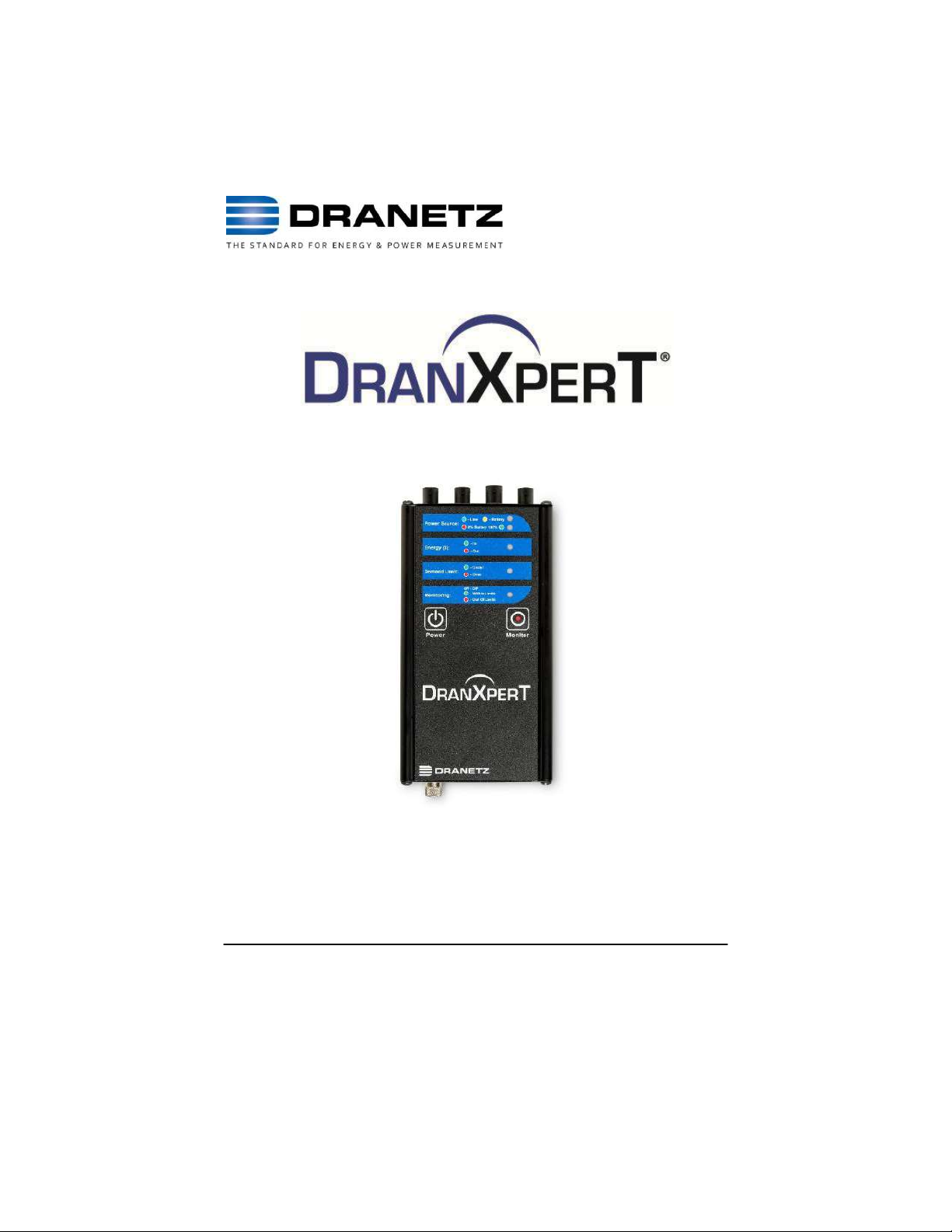
Quick Reference Guide
Dranetz
Find Quality Products Online at: [email protected]
www.GlobalTestSupply.com
Page 2

WARNING
Death, serious injury, or fire hazard could result from improper
connection of this instrument. Read and understand this manual before
connecting this instrument. Follow all installation and operating
Instructions while using this instrument.
Connection of this instrument must be performed in compliance with the
National Electrical Code (ANSI/NFPA 70-2020) of USA and any
additional safety requirements applicable to your installation.
Installation, operation, and maintenance of this instrument must be
performed by qualified personnel only. The National Electrical Code
defines a qualified person as “one who has the skills and knowledge
related to the construction and operation of the electrical equipment and
installations, and who has received safety training on the hazards
involved.”
Qualified personnel who work on or near exposed energized electrical
conductors must follow applicable safety related work practices and
procedures including appropriate personal protective equipment in
compliance with the Standard for Electrical Safety Requirements for
Employee Workplaces (ANSI/NFPA 70E-2021) of USA and any
additional workplace safety requirements applicable to your installation.
No part of this book may be reproduced, stored in a
retrieval system, or transcribed in any form or by any
means—electronic, mechanical, photocopying, recording,
or otherwise—without prior written permission from the
publisher, Dranetz, Edison, NJ 08817.
Printed in the United States of America.
1
Find Quality Products Online at: [email protected]
www.GlobalTestSupply.com
Page 3

ADVERTENCIA
Una conexión incorrecta de este instrumento puede producir la muerte,
lesiones graves y riesgo de incendio. Lea y entienda este manual antes de
conectar. Observe todas las instrucciones de instalación y operación durante
el uso de este instrumento.
La conexión de este instrumento a un sistema eléctrico se debe realizar en
conformidad con el Código Eléctrico Nacional (ANSI/NFPA 70-2020) de los
E.E.U.U., además de cualquier otra norma de seguridad correspondiente a
su establecimiento.
La instalación, operación y mantenimiento de este instrumento debe ser
realizada por personal calificado solamente. El Código Eléctrico Nacional
define a una persona calificada como "una que esté familiarizada con la
construcción y operación del equipo y con los riesgos involucrados."
El personal cualificado que trabaja encendido o acerca a los conductores
eléctricos energizados expuestos debe seguir prácticas y procedimientos
relacionados seguridad aplicable del trabajo incluyendo el equipo protector
personal apropiado en conformidad con el estándar para los requisitos de
seguridad eléctricos para los lugares de trabajo del empleado (ANSI/NFPA
70E-2021) de los E.E.U.U. y cualquier requisito de seguridad adicional del
lugar de trabajo aplicable a su instalación.
AVERTISSEMENT
Si l'instrument est mal connecté, la mort, des blessures graves, ou un
danger d'incendie peuvent s'en suivre. Lisez attentivement ce manuel avant
de connecter l'instrument. Lorsque vous utilisez l'instrument, suivez toutes
les instructions d'installation et de service.
Cet instrument doit être connecté conformément au National Electrical Code
(ANSI/NFPA 70-2020) des Etats-Unis et à toutes les exigences de sécurité
applicables à votre installation.
Cet instrument doit être installé, utilisé et entretenu uniquement par un
personnel qualifié. Selon le National Electrical Code, une personne est
qualifiée si "elle connaît bien la construction et l'utilisation de l'équipement,
ainsi que les dangers que cela implique".
Le personnel qualifié qui travaillent dessus ou s'approchent des conducteurs
électriques activés exposés doit suivre des pratiques en matière et des
procédures reliées par sûreté applicable de travail comprenant le matériel de
protection personnel approprié conformément à la norme pour des
conditions de sûreté électriques pour les lieux de travail des employés
(ANSI/NFPA 70E-2021) des Etats-Unis et toutes les conditions de sûreté
additionnelles de lieu de travail applicables à votre installation.
2
Find Quality Products Online at: [email protected]
www.GlobalTestSupply.com
Page 4

WARNUNG
Der falsche Anschluß dieses Gerätes kann Tod, schwere Verletzungen oder
Feuer verursachen. Bevor Sie dieses Instrument anschließen, müssen Sie
die Anleitung lesen und verstanden haben. Bei der Verwendung dieses
Instruments müssen alle Installation- und Betriebsanweisungen beachtet
werden.
Der Anschluß dieses Instruments muß in Übereinstimmung mit den
nationalen Bestimmungen für Elektrizität (ANSI/NFPA 70-2020) der
Vereinigten Staaten, sowie allen weiteren, in Ihrem Fall anwendbaren
Sicherheitsbestimmungen, vorgenommen werden.
Installation, Betrieb und Wartung dieses Instruments dürfen nur von
Fachpersonal durchgeführt werden. In dem nationalen Bestimmungen für
Elektrizität wird ein Fachmann als eine Person bezeichnet, welche "mit der
Bauweise und dem Betrieb des Gerätes sowie den dazugehörigen Gefahren
vertraut ist."
Qualifiziertes Personal, das an bearbeiten oder herausgestellte angezogene
elektrische Leiter sich nähern, muß anwendbare Sicherheit bezogener Arbeit
Praxis und Verfahren einschließlich passende persönliche schützende
Ausrüstung gemäß dem Standard für elektrische Sicherheitsauflagen für
Angestellt-Arbeitsplätze (ANSI/NFPA 70E-2021) der Vereinigten Staaten und
alle zusätzlichen Arbeitsplatzsicherheitsauflagen folgen, die auf Ihre
Installation anwendbar sind.
Safety Summary
Definitions
WARNING statements inform the user that certain conditions or
practices could result in loss of life or physical harm.
CAUTION statements identify conditions or practices that could harm the
instrument, its data, other equipment, or property.
NOTE statements call attention to specific information.
Symbols
The following International Electrotechnical Commission (IEC) symbols
are marked on the top and rear panel in the immediate vicinity of the
referenced terminal or device:
3
Find Quality Products Online at: [email protected]
www.GlobalTestSupply.com
Page 5
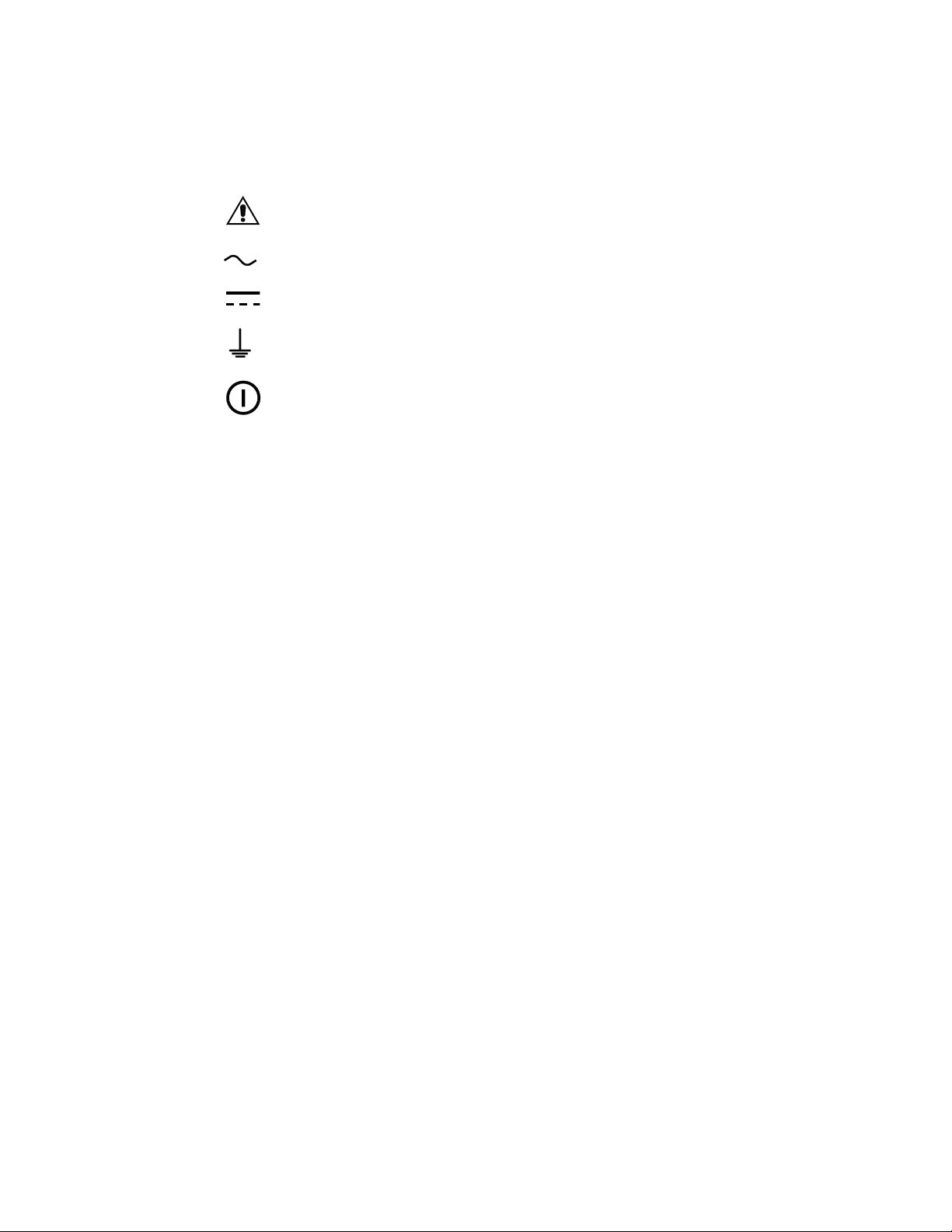
Caution, refer to accompanying documents (this manual).
Alternating current (AC) operation of the terminal or device.
Direct current (DC) operation of the terminal or device.
Earth (ground) terminal
Power switch
Safety Precautions
The following safety precautions must be followed whenever any type of
voltage or current connection is being made to the instrument.
• Connect the earth (ground) terminal first, before making any other
connections.
• When connecting to electric circuits or pulse initiating equipment,
open their related breakers. DO NOT install any connection of the
instrument on live power lines.
• Connections must be made to the instrument first, then connect to the
circuit to be monitored.
• Wear proper personal protective equipment, including safety glasses
and insulated gloves when making connections to power circuits.
• Hands, shoes, and floor must be dry when making any connection to
a power line.
• Make sure the instrument is turned OFF before connecting probes to
the rear panel.
• Before each use, inspect all cables for breaks or cracks in the
insulation. Replace immediately if defective.
• If the equipment is used in a manner not specified in this reference
guide, the protection provided by the equipment may be impaired.
These safety precautions are repeated where appropriate throughout
this manual.
4
Find Quality Products Online at: [email protected]
www.GlobalTestSupply.com
Page 6

Table of Contents
INTRODUCTION ..................................................................6
GETTING STARTED ............................................................7
Connecting to the Power Source .......................................8
Controls, Indicators and Connectors ............................... 10
CONNECTING TO DRANXPERT ....................................... 14
Connecting via Wired Ethernet Connection ..................... 15
Making Measurement Connections ................................. 17
Measurement Connectors for DranXperT........................ 18
Connecting Voltage Measurement Cables ...................... 19
Connecting Current Probes ............................................. 20
DranXperT USER INTERFACE .......................................... 28
Home/Information Page .................................................. 28
Instrument Settings ......................................................... 29
Real-Time Measurements ............................................... 36
Downloading and Managing Data ................................... 38
Factory Settings .............................................................. 41
START/STOP MONITORING ............................................. 44
Start Monitoring ............................................................... 44
Stop Monitoring ............................................................... 45
VIEWING RECORDED DATA ............................................ 46
Copying Data from DranXperT ........................................ 46
Opening Data in Dran-View XP ....................................... 46
Standard Accessories ..................................................... 48
Optional Accessories ....................................................... 49
SPECIFICATIONS* ............................................................. 50
STATEMENTS AND NOTICES .......................................... 52
5
Find Quality Products Online at: [email protected]
www.GlobalTestSupply.com
Page 7

INTRODUCTION
DranXperT
DranXperT not only meters, records, and trends what you expect from a
power logger, but it also measures harmonics and detects voltage
Sags/Dips, Swells, and Interruptions down to one cycle in duration.
DranXperT has three voltage and four current channels, and can be
used in single, two, and three phase monitoring applications. The fourth
current channel can be used for monitoring the neutral or other current
sources.
DranXperT can be used in a wide range of applications, including realtime metering, long-term power and energy studies, and basic power
quality surveys. DranXperT can be used in portable, temporary, remote,
or fixed installed applications.
All user interactions with DranXperT are performed using a web browser
through a simple network connection, which can be local, via a direct
connection to a computer, or remote by using a hub, switch, company
network, or the Internet. Once connected to a network, any computing
device with a web browser can be used to configure DranXperT, view
real-time metering information, and copy recorded data from the
instrument.
DranXperT data is fully compatible with Dran-View® XP Windows
software, which is a free, unlicensed, ‘lite’ version of our popular DranView 7 PRO software. DranXperT data can also be viewed using the full
versions of Dran-View 7 PRO or Enterprise.
®
is a very accurate three-phase power and energy logger.
6
Find Quality Products Online at: [email protected]
www.GlobalTestSupply.com
Page 8

GETTING STARTED
IMPORTANT NOTICE
Charge Battery Before Use
Always charge the battery fully before using the instrument!
The instrument will fully charge its internal battery in
approximately 15 hours.
The instrument will always operate on the AC power source
(when available) and is designed to do so regardless of the state
of charge of the battery.
Dran-View XP Analysis Software (free download)
Dran-View XP analysis and reporting software is available as a
free download from our web site for use with DranXperT.
Current Dran-View 7 Pro or Enterprise users can update their
existing Dran-View 7 software at no charge for use with
DranXperT. Dran-View V7.7.08 or newer is required for use with
DranXperT. Dran-View 7 can be upgraded using the built-in
automatic update feature or by downloading from your web site.
7
Find Quality Products Online at: [email protected]
www.GlobalTestSupply.com
Page 9

Connecting to the Power Source
Power The DranXperT AC adapter can be powered by a 50/60
Specifications Hz, 15W, 90-264V AC power input source.
CAUTION Always set the power switch to the off position
PRECAUCION Siempre fije el interruptor de encendido en la
La operación del DranXperT desde una fuente de
MISE EN Mettez toujours l’interrupteur dans la position
GARDE ouverte avant de connecter ou de déconnecter le
câble d’alimentation primaire.
Le fonctionnement du DranXperT à partir d'une
source de tension alternative autre que l'entrée de
tension nominale indiquée sur la plaque signalétique
de l'unité peut endommager l'unité.
VORSICHT Vor dem Einstecken bzw. Ausstecken des
Der Betrieb des DranXperT von einer
before connecting or disconnecting the input power
cable.
Operation of the DranXperT from an AC voltage
source other than the rated voltage input stated on
the instrument nameplate can cause damage to the
instrument.
posición apagada antes de conectar o desconectar
el cable de energía de entrada.
voltaje de ca que no sea la entrada de voltaje
nominal indicada en la placa de identificación de la
unidad puede causar daños a la unidad.
Eingangsnetzkabels den Netzschalter immer in die
Aus-Stellung bringen.
Wechselspannungsquelle, die nicht dem auf der
Namensplatte der Einheit aufgeführten
Nennspannungseingang entspricht, kann
zur Beschädigung der Einheit führen.
8
Find Quality Products Online at: [email protected]
www.GlobalTestSupply.com
Page 10
Step
Action
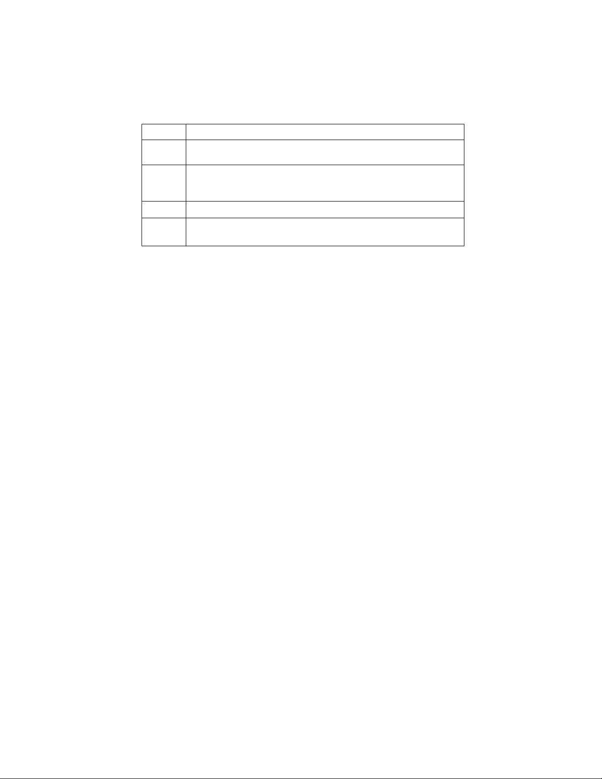
1
Connect the AC adapter/battery charger plug to the DC input
of the instrument
2
Connect the appropriate power cord for the voltage rating of
the instrument to the AC adapter/battery charger.
3
Plug the AC adapter into an AC power source
4
Press the momentary On/Off power switch to turn the
instrument on.
9
Find Quality Products Online at: [email protected]
www.GlobalTestSupply.com
Page 11
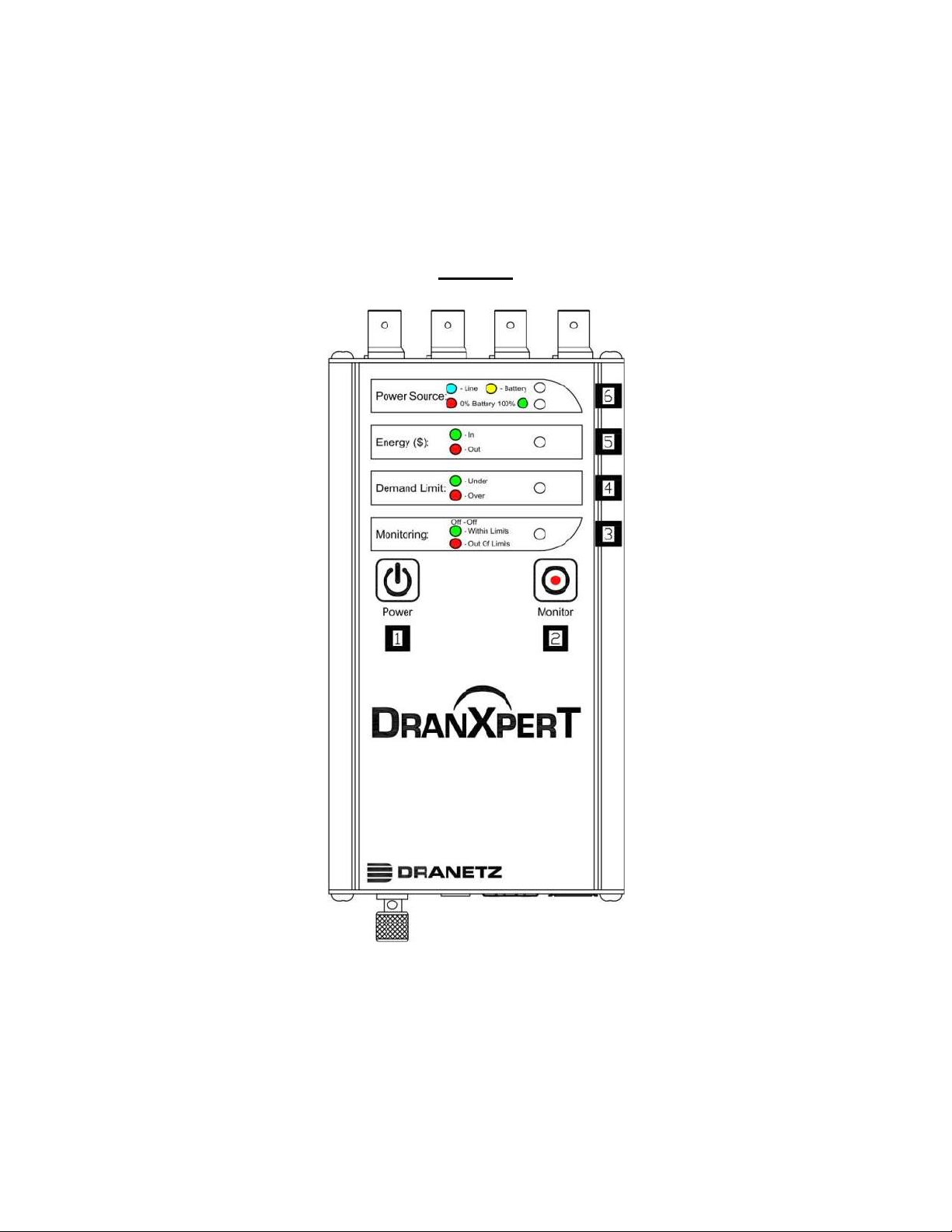
Controls, Indicators and Connectors
Top View
10
Find Quality Products Online at: [email protected]
www.GlobalTestSupply.com
Page 12
2
3
4
5
6
Power Button – press to turn the instrument power ON or OFF
Monitoring Button – press and hold for approximately 5 seconds
until a single beep is heard to turn monitoring ON or OFF
Monitoring Status – LED status indicator
Monitoring Off: LED = OFF (No LED)
Monitoring Limits Within Trigger Limits: LED = GREEN
Monitoring Limits Out of Trigger Limits: LED = RED
Demand Limit – LED status indicator
Under Demand Limit: LED = GREEN
Over Demand Limit: LED = RED
Energy ($) – LED status indicator
Exporting (producing) Energy: LED = GREEN
Importing (consuming) Energy: LED = RED
Power Source – LED status indicators
Top LED – Instrument power source:
Instrument powering up: LED = GREEN
Operating on external power source: LED = BLUE
Operating on internal battery: LED = YELLOW
Bottom LED – Battery status
Depleted (0%): LED = RED
Charging/Discharging: LED = Shades of YELLOW from
charged to discharged & vice versa
Fully charged (100%): LED = GREEN 100%
11
Find Quality Products Online at: [email protected]
www.GlobalTestSupply.com
Page 13
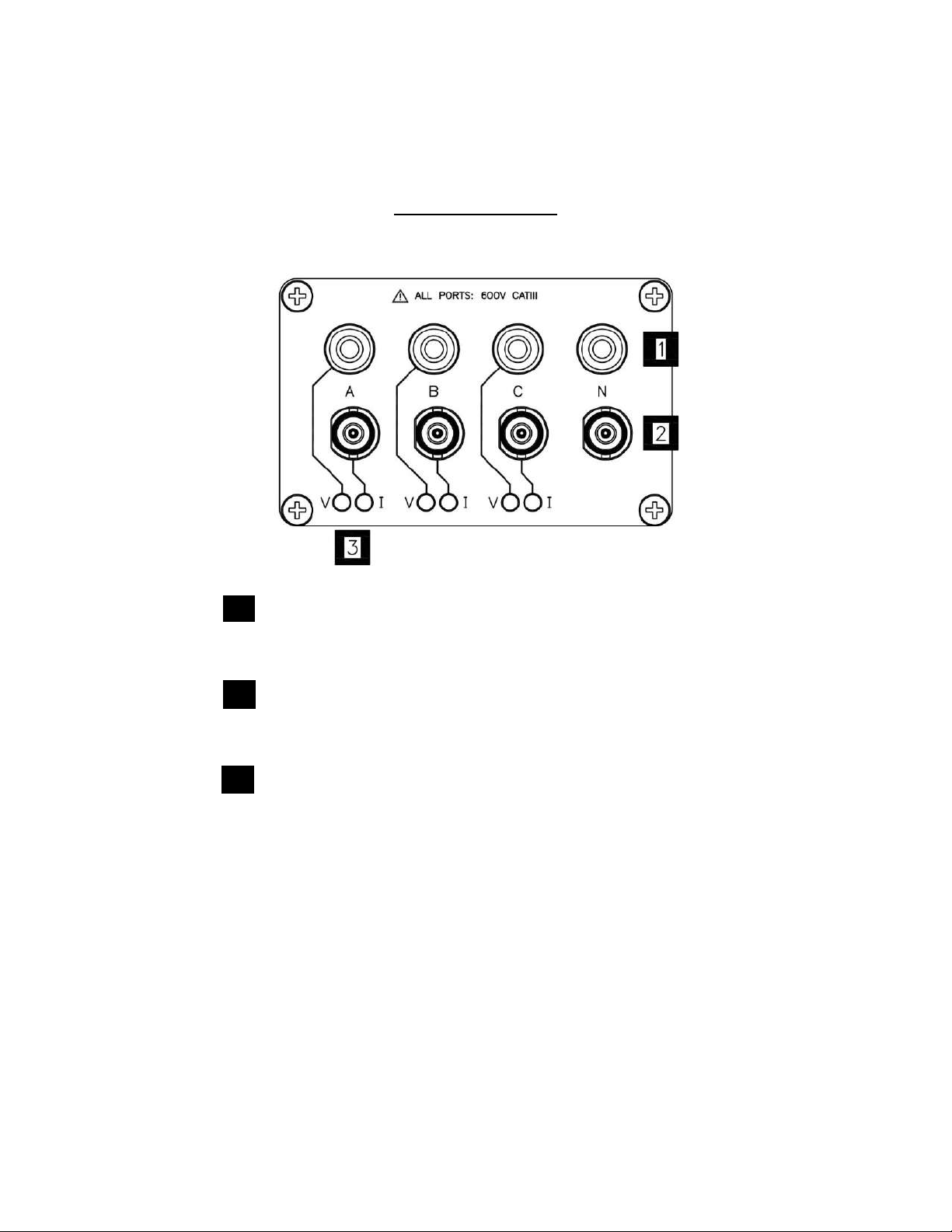
Top End Panel View
2
3
This section describes the top end panel view of DranXperT.
Voltage Inputs – use to connect the circuit voltage to the
instrument channels A, B, C, and N using safety cables with
banana connectors. See section Connecting the Voltage and
Current Connectors for circuit connection details.
Current Inputs – use to connect compatible current probes with
an insulated BNC connector to the instrument channels A, B, C
and N. See section Connecting the Voltage and Current
Connectors for circuit connection details.
V and I Connection LEDs – color coded to indicate the status of
channels A, B, C for voltage and current.
LED Colors (colors can be changed in the instrument setups)
Channel A = RED
Channel B = YELLOW
Channel C = BLUE
LED Operation
V or I applied: LED is solid in the channel color above
No V or I applied: LED flashes in the channel color above
V sequence error (if enabled): LED flashes RED if monitoring
= ON
12
Find Quality Products Online at: [email protected]
www.GlobalTestSupply.com
Page 14
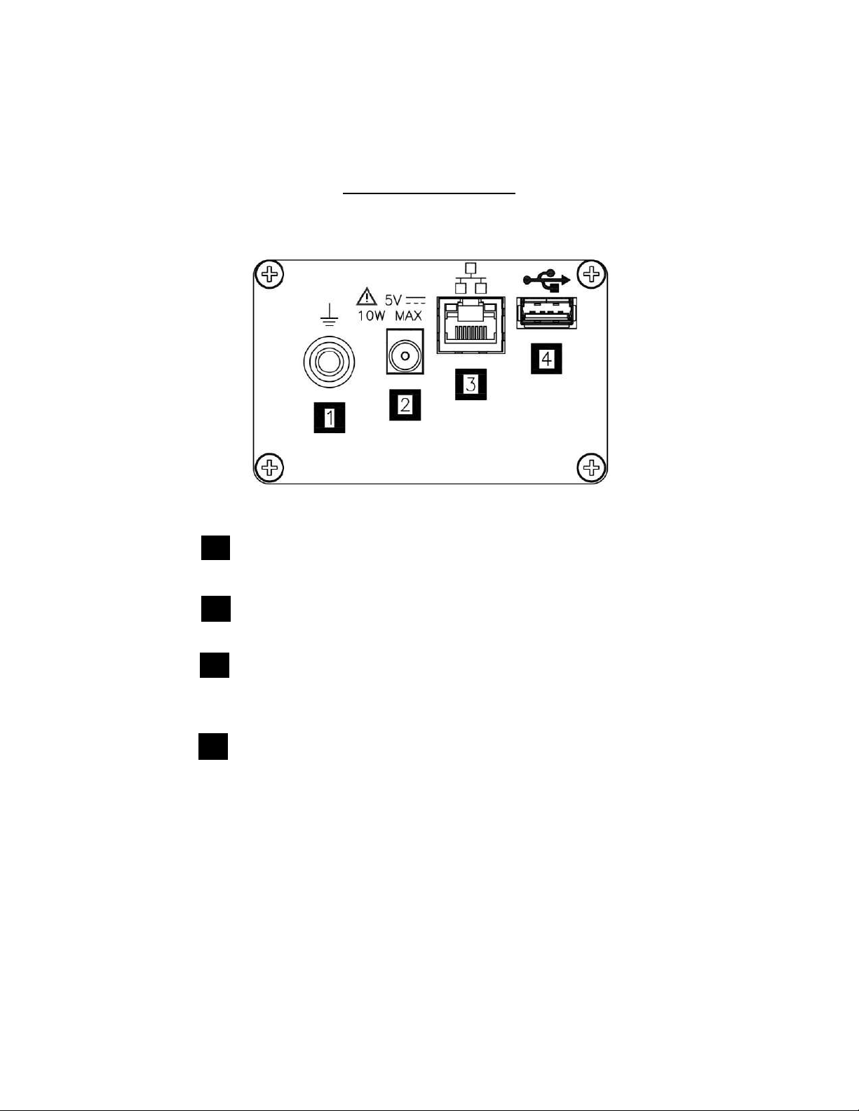
Bottom End Panel View
2
3
4
This section describes the bottom end panel view of DranXperT.
Ground Terminal – earth (ground) terminal reference connection
to maintain accurate measurements.
DC Power Input –external AC adapter/battery charger input.
Ethernet – Wired Ethernet (RJ45) network connector.
Depending on your computer, an Ethernet crossover cable (not
included) may be required to connect directly to a computer when
not using a network.
USB – use for data transfer to a USB drive.
13
Find Quality Products Online at: [email protected]
www.GlobalTestSupply.com
Page 15
Connecting via Wired Ethernet Connection
Step
Action
1
Connect an Ethernet cable between your computer and the
Ethernet port at the rear panel of the instrument. An Ethernet
cross-over cable may be needed if the computer cannot autodetect direct cabling.
2
Connect the power source at the rear panel of the instrument.
3
Power ON the computer, then press the DranXperT power
button on the top panel to turn the instrument ON.
4
When using DranXperT for the first time, to complete the
Ethernet connection, the computer’s IP address needs to be
changed to be on the same network as DranXperT’s default IP
address. This involves changing the IP address properties of
your computer. Please contact your IT departmen
5
Once the computer’s IP address has been properly configured,
open a web browser and enter the following (default IP
address) into the address bar: http://192.168.0.40.
6
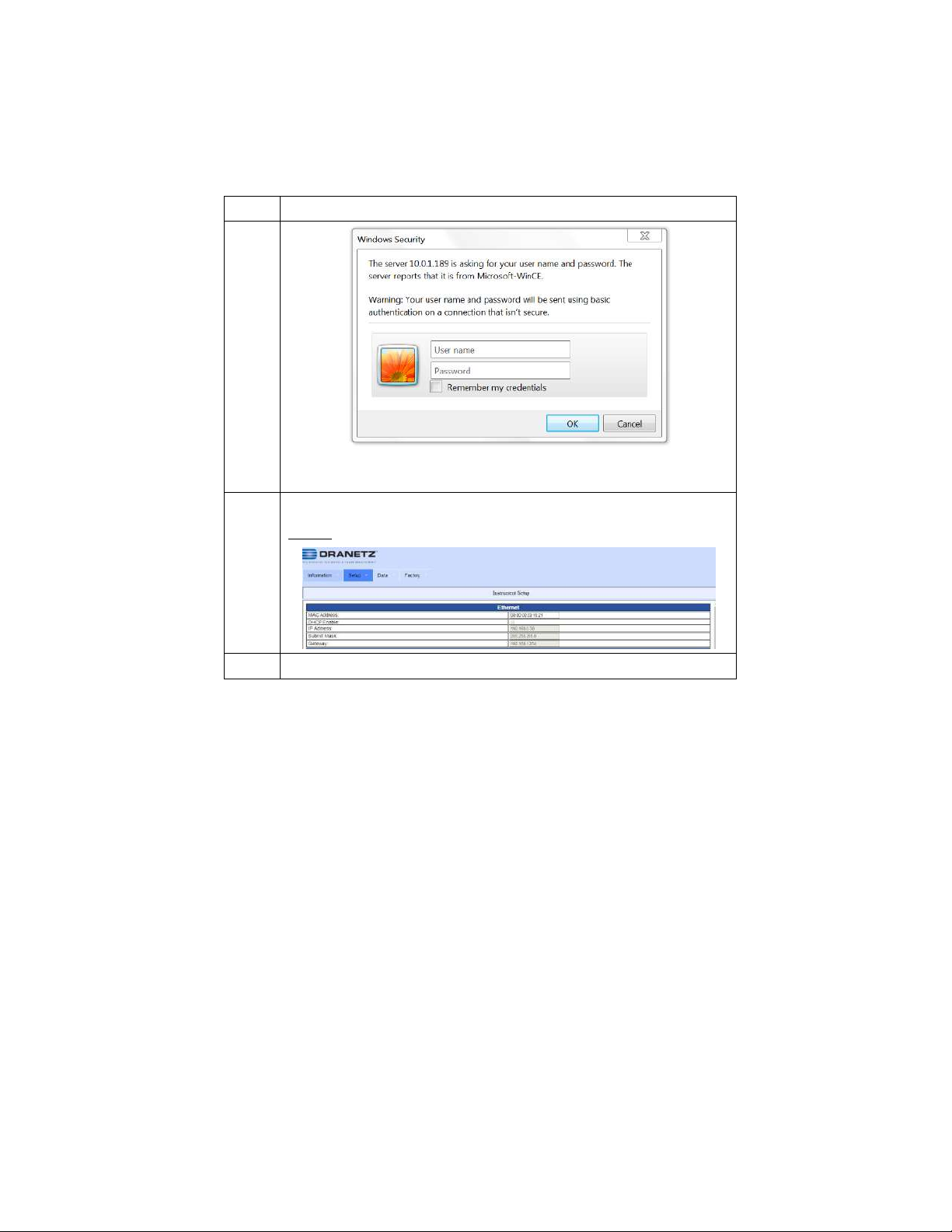
If communications to the instrument are working properly, the
login window below will be displayed, prompting you to enter
the username and password. If you do not see the message
below your computer’s network settings may not be properly
configured or an incorrect IP address is being used.
Enter the default Username: admin
Enter the default Password: Dranetz
The username and password are case-sensitive and must be
entered as shown.
The steps below show how to connect to DranXperT via a wired Ethernet
connection.
15
Find Quality Products Online at: [email protected]
www.GlobalTestSupply.com
Page 16
Step
Action
When finished entering the username and password, click the
OK button.
7
The DranXperT Home Page will then be displayed.
Result: The following screen is displayed.
16
Find Quality Products Online at: [email protected]
www.GlobalTestSupply.com
Page 17

Making Measurement Connections
WARNING
Death, serious injury, or fire hazard could result from
improper connection of this instrument. Read and
understand the warnings in the beginning of this guide
before connecting this instrument.
ADVERTENCIA
Una conexión incorrecta de este instrumento puede
producir la muerte, lesiones graves y riesgo de incendio.
Lea y entienda este manual antes de conectar. Observe
todas las instrucciones de instalación y operación durante
el uso de este instrumento.
AVERTISSEMENT
Si l'instrument est mal connecté, la mort, des blessures
graves, ou un danger d'incendie peuvent s'en suivre. Lisez
attentivement ce manuel avant de connecter l'instrument.
Lorsque vous utilisez l'instrument, suivez toutes les
instructions d'installation et de service.
WARNUNG
Der falsche Anschluß dieses Gerätes kann Tod, schwere
Verletzungen oder Feuer verursachen. Bevor Sie dieses
Instrument anschließen, müssen Sie die Anleitung lesen
und verstanden haben. Bei der Verwendung dieses
Instruments müssen alle Installation-und
Betriebsanweisungen beachtet werden.
17
Find Quality Products Online at: [email protected]
www.GlobalTestSupply.com
Page 18

Measurement Connectors for DranXperT
Voltage
Measurement
Cables
Current Probes
Voltage Measurement Cables: Voltage measurement
cables and clips are provided as standard
accessories.
Current Probes (for Current Measurements): A variety
of optional current probes are available. See the
Optional Accessories section below.
DranXperT has three (3) voltage and four (4) current channels which can
be used to measure a wide variety of circuit types.
DranXperT comes with a voltage cable set for making voltage
connections. Current measurements are made using the optional current
probes available from Dranetz. Note that a variety of kits are available
from Dranetz that include current probes.
Use only Dranetz voltage leads, current probes, and adapter cables for
proper operation and safety. Do not exceed the marked maximum
ratings.
18
Find Quality Products Online at: [email protected]
www.GlobalTestSupply.com
Page 19

Connecting Voltage Measurement Cables
Measurement
cable set
Description: Voltage measurement cables are used to
connect to your circuit via safety banana jack
connectors and alligator clips.
Voltage Rating: Direct connection of all voltage
measurement inputs are rated at 600 VRMS max.
When measuring voltages greater than 600 VRMS,
potential transformers (PTs) or other transducers must
be used.
Contents: A cable set consists of four (1 red, 1 yellow,
1 blue, 1 white) 6-foot voltage measurement cables,
each with a detachable alligator jaw safety clip
assembly (maximum jaw opening, 3/4 in (20 mm)).
There are three (3) black and one (1) white safety
clips.
19
Find Quality Products Online at: [email protected]
www.GlobalTestSupply.com
Page 20

Connecting Current Probes
Types of
current probes
Safety
Precautions
The instrument uses an insulated BNC type connector
for connection of current probes to channels A, B, C
and N.
WARNING
Use only probes that are rated 600V CAT III or higher.
DO NOT use other probe types, including probes that
use uninsulated connectors.
Probe positioning: The arrow marking on the current
probe should be pointed in the direction of current flow
and towards the load. To reduce measurement errors,
it is always “best practice” to center the conductor in
the probe. Correct position of the probe is necessary
for correct power measurements, where in-phase
voltage and current measurements are necessary.
The following safety precautions apply to current
probe connections.
DO NOT attempt to measure current in any circuit
in which the circuit to ground voltage exceeds the
insulation rating of the current probe (example: 600
VRMS max).
Make sure the current probes are tightly closed.
Keep mating surfaces clean and free from foreign
matter.
20
Find Quality Products Online at: [email protected]
www.GlobalTestSupply.com
Page 21

WARNING
ADVERTENCIA
AVERTISSEMENT
WARNUNG
DO NOT USE non-insulated current probe cores
around a non-insulated wire. Probes of this type
are designed for use around insulated wires only.
Use only completely insulated probe cores with
no exposed conductive areas of the core around
non-insulated wires.
NO UTILIZAR transformadores de corriente sin
material aislante al rededor de conductores sin
material aislante. Los Transformadores de
corriente de este tipo est‡n dise–ados para ser
utilizados solamente con conductores con
aislamiento elŽctrico. Utilizar transformadores de
corriente completamente aislados alrededor de
conductores sin aislamiento.
N'EMPLOYEZ PAS les noyaux courants non-
isolŽs de sonde autour d'un fil nonisolŽ. Des
sondes de ce type sont concues pour l'usage
autour des fils isolŽs seulement. L'utilisation
seulement a complŽtement isolŽ des noyaux de
sonde sans des secteurs conducteurs exposŽs
du noyau autour des fils non-isolŽs.
VERWENDEN Sie keine Stromzangen mit nicht
isolierten Ferritkernen bei Messungen an nicht
isolierten Leitungen. Stromzangen dieses Typs
sind nur fŸr Messungen an isolierten Leitern
geeignet. Bitte verwenden Sie zur Messung an
nicht isolierten Leitungen Stromzangen mit
vollstŠndig isoliertem Kernmaterial
21
Find Quality Products Online at: [email protected]
www.GlobalTestSupply.com
Page 22

Connection Guidelines
Voltage and
Current
connections
Voltage: As per the diagrams below, voltage probes
are connected to the individual source or load lines
and are referenced to the return (common).
Current: As per the diagrams below, current probes
are connected to each line and positioned to measure
currents with reference to the voltage probe.
Incorrectly positioned current probes may produce
erroneous current and power measurement. Current
probes are always oriented with the arrow pointing to
the load.
Connect current probes with the instrument powered
“OFF”. After you have made the applicable
connections for your installation, power “ON” the
instrument.
Next, select the applicable current probe settings,
refer to “Survey Setup” section page 29.
WARNING
WARNING
To reduce the risk of fire, electric shock, or physical
injury, it is strongly recommended that connections be
made with all circuits de-energized and current
carrying conductors fused. If it is necessary to make
connections on energized circuits, these must be
performed by Qualified Personnel ONLY with proper
Personal Protective Equipment.
To avoid the risk of electric shock or burns, always
connect the earth ground before making any other
connections.
Refer to the appropriate connection diagram on the pages below for the
desired circuit type.
---------------------------------------------------------------------------------
DranXperT can monitor the following power configurations:
Find Quality Products Online at: [email protected]
Single Phase
Split Phase
3 Phase, Four Wire Wye
3 Phase, Three Wire Delta (2 or 3 probe)
22
www.GlobalTestSupply.com
Page 23
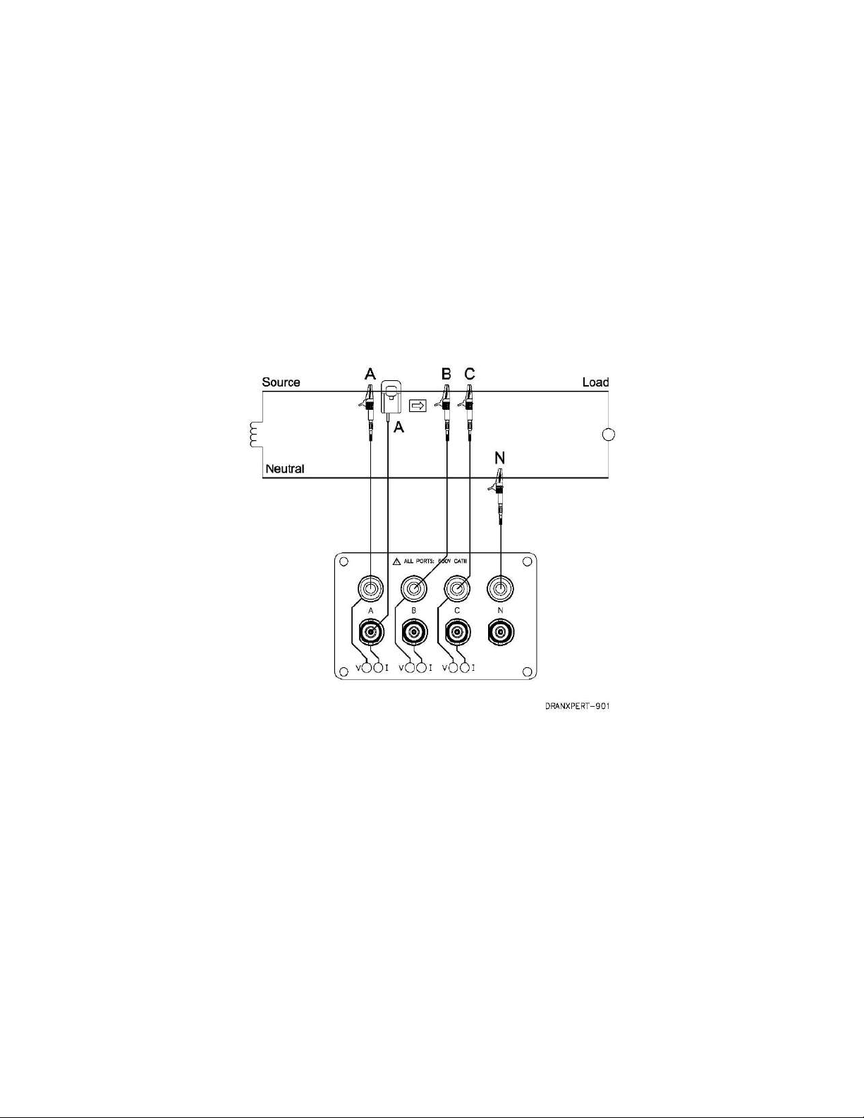
Single Phase
When making single phase measurements, use channel A as shown
below. The Neutral is chosen as the reference for measurement
purposes. You may optionally measure the Neutral current by connecting
a current probe to the Neutral conductor and to the N channel current
input.
NOTE Be sure to connect the current probes with the arrow
pointing towards the load or an erroneous power reading
will result.
23
Find Quality Products Online at: [email protected]
www.GlobalTestSupply.com
Page 24
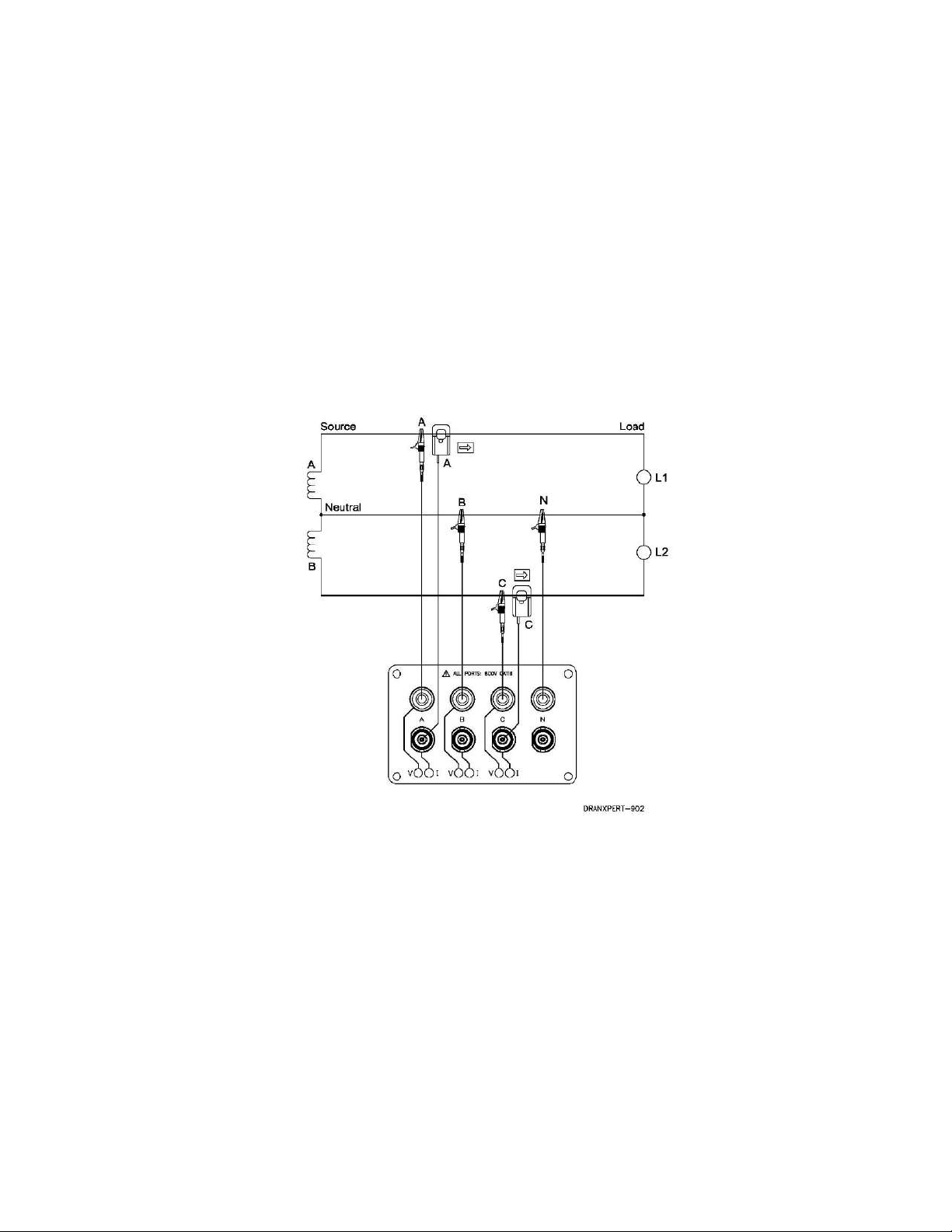
Split Phase
When making split phase measurements, use both channels A and C for
voltage and current connections. The Neutral is chosen as the reference
for measurement purposes. You may optionally measure the Neutral
current by connecting a current probe to the Neutral conductor and to the
N channel current input.
NOTE Be sure to connect the current probes with the arrow
pointing towards the load or an erroneous power reading
will result.
24
Find Quality Products Online at: [email protected]
www.GlobalTestSupply.com
Page 25
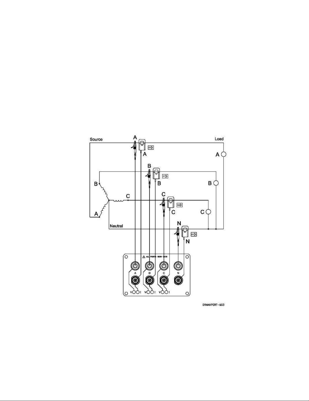
3 Phase, Four Wire Wye
Channels A, B, and C are connected to the voltage and current probes.
The neutral is connected to common and is the reference for the three
voltage channels. Note that the Neutral current measurement is optional.
NOTE Be sure to connect the current probes with the arrow
pointing towards the load or an erroneous power reading
will result.
25
Find Quality Products Online at: [email protected]
www.GlobalTestSupply.com
Page 26
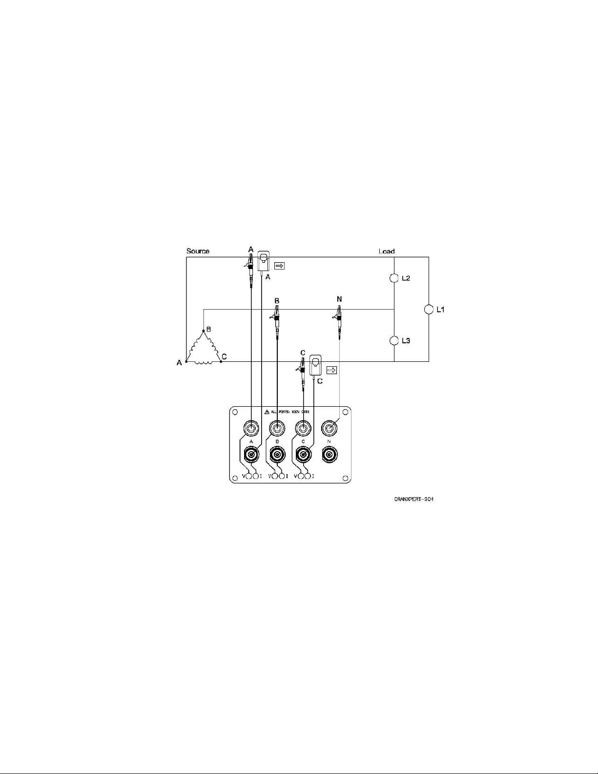
3 Phase, 2 probe Delta
The figure below shows the 3 Phase, 2 probe, 2 wattmeter delta
connection using phase channels A-B-C. The N channel is connected to
phase B as the reference for measurement purposes. Current probes are
connected to measure line currents A and C.
NOTE Be sure to connect the current probes with the arrow
pointing towards the load or an erroneous power reading
will result.
26
Find Quality Products Online at: [email protected]
www.GlobalTestSupply.com
Page 27
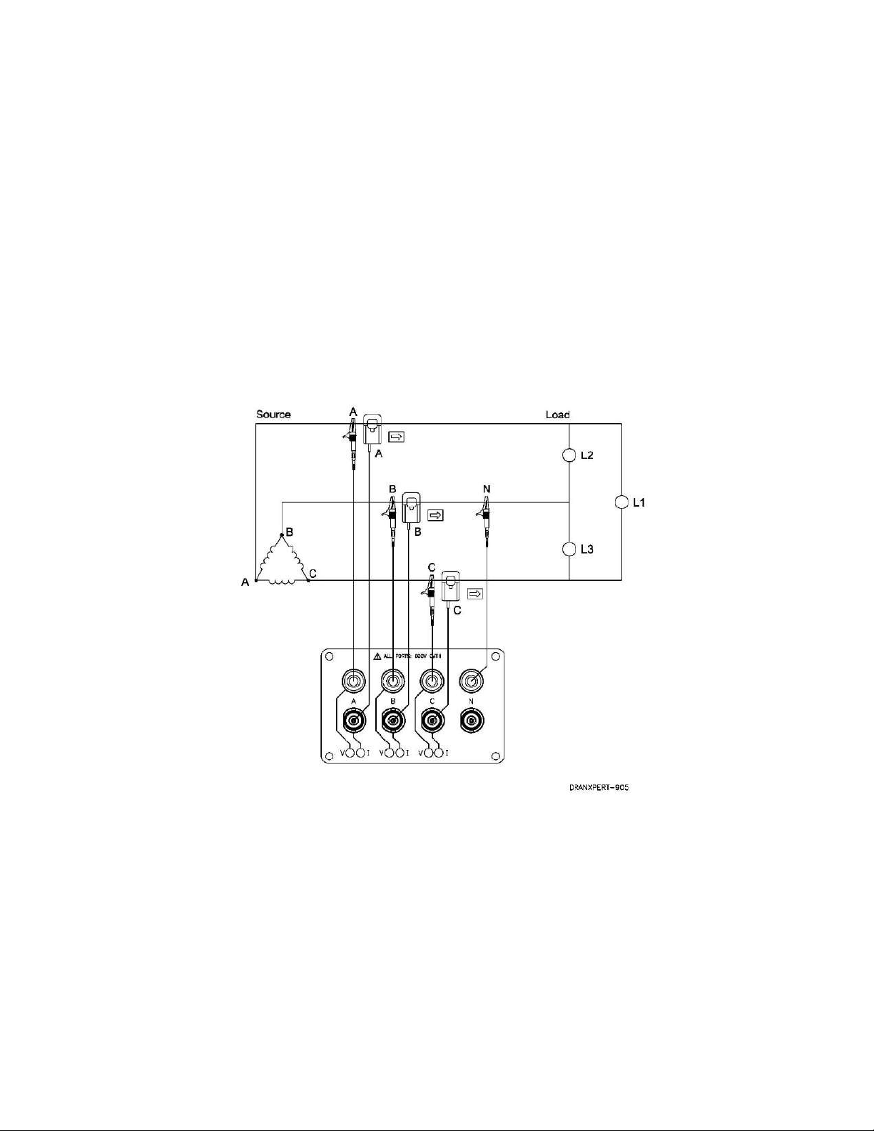
3 Phase, 3 probe Delta
The figure below shows the 3 Phase, 3 probe, 2 wattmeter delta
connection using phase channels A-B-C. The N channel is chosen as the
reference and is connected to phase B for measurement purposes.
Current probes are connected to measure line currents A, B and C. Note
that the B current probe is connected to measure the B phase current
only and is not included as part of the power computations.
NOTE Be sure to connect the current probes with the arrow
pointing towards the load or an erroneous power reading
will result.
27
Find Quality Products Online at: [email protected]
www.GlobalTestSupply.com
Page 28
DranXperT USER INTERFACE
Home/Information Page
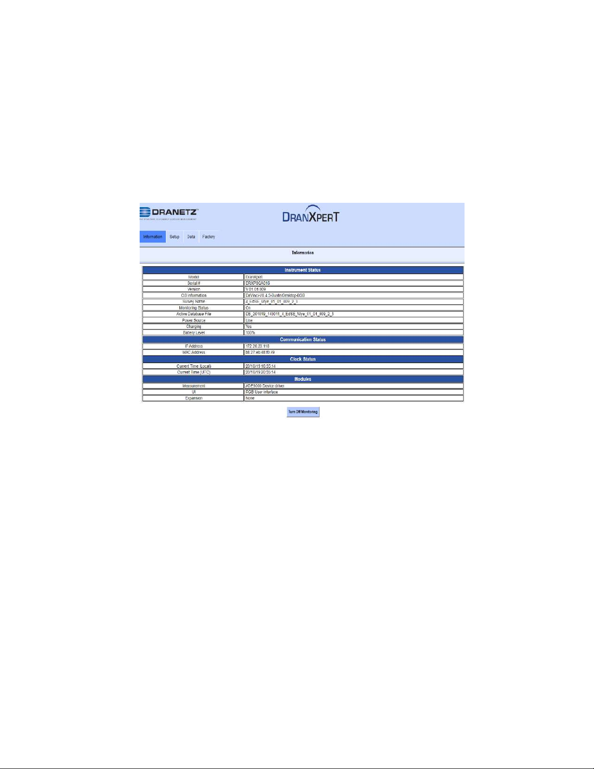
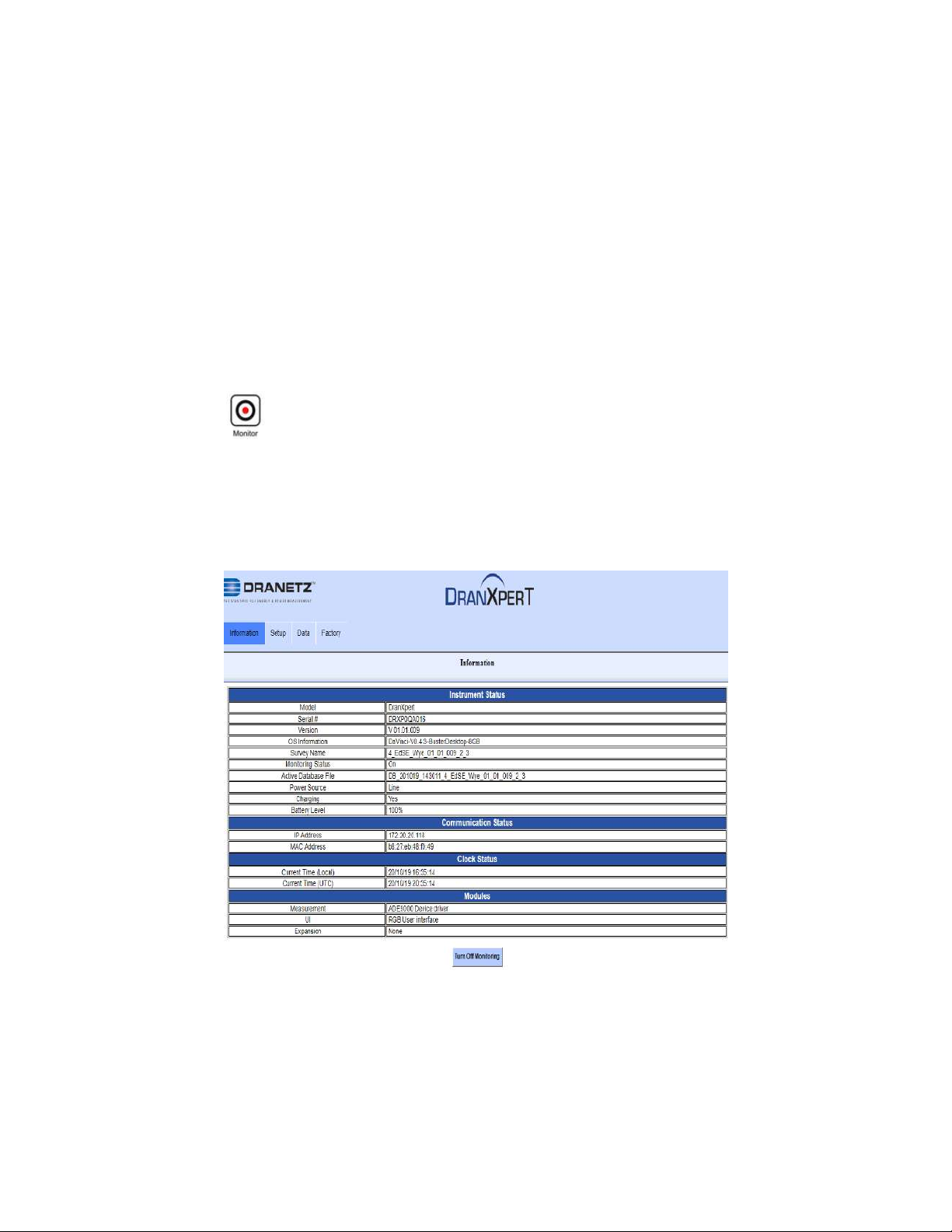
When first connecting to DranXperT, the Information page will be
displayed. This page is also available by selecting Information > Status in
the menu. See below.
The Information page provides instrument status information, such as the
serial number, firmware version, monitoring state, power source/battery
charge status, IP address, and current time.
At the bottom of the page, there is a button to turn monitoring ON or
OFF. If monitoring is OFF, click this button to turn monitoring ON, and
vice versa. This button serves the same purpose as the monitoring
ON/OFF button located on the front panel. You can use either to control
the state of the insturment monitoring.
Note that when monitoring is ON, the monitoring and instrument settings
described below are “view only” and cannot be modified until monitoring
is turned OFF.
28
Find Quality Products Online at: [email protected]
www.GlobalTestSupply.com
Page 29
Instrument Settings
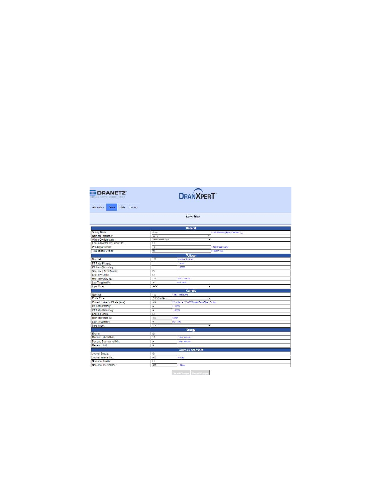
Once you have connected to DranXperT via a web browser, you can
view and edit the instrument’s settings as described below.
Survey Setup
Select Setup > Survey Setup to view/change the current monitoring
settings of the instrument.
Note that the survey setings can only be modified if monitoring is OFF. If
monitoring is ON, you will receive a warning that the survey settings are
“view only”.
29
Find Quality Products Online at: [email protected]
www.GlobalTestSupply.com
Page 30
General
Survey Name - Enter a name (up to 48 characters) that describes your
survey. This name will be inlcuded in the name of the data file recorded.
Nominal Frequency – Dropdown selection, either 50 Hz or 60 Hz.
Wiring Configuration – Dropdown selections are: Single Phase, Split
Phase, Three-Phase Wye, Three-Phase Delta 2 probes, Three-Phase
Delta 3 probes.
Enable Monitor On Power Up – Checkbox enable/disable. When
checked, if the instrument resets, such as when power is restored after
the battery has depleted, monitoring will be re-enabled upon restart if
moniting was previously ON.
Pre-trigger Cycles – Number of pre-trigger RMS points (in cycles) to
record when exceeding the voltage or current trigger limits set below.
Must be less than the Total Trigger Cycles.
Total Trigger Cycles – Total number of RMS points (in cycles) to record
when exceeding the voltage or current trigger limits set below. Entry
range is from 0 to 600 Cycles.
Voltage
Nominal – Nominal voltage. Settable range is 90 – 600VRMS.
PT Ratio Primary – PT primary (if applicable). Settable range is 1 –
65535.
PT Ratio Secondary – PT secondary (if applicable). Settable range is 1 –
65535.
Sequence Error Enable – Checkbox enable/disable. Enables connection
panel LED notification of a voltage sequence/connection error. The LEDs
will flash RED if enabled and a voltage sequence error exists.
High Threshold % – Voltage high trigger limit. Settable range is 100 –
500% of the nominal voltage setting.
Low Threshold % – Voltage low trigger limit. Settable range is 0 – 100%
of the nominal voltage setting.
Input Order – Dropdown selectable. Corrects for voltage wiring mistakes.
Selections are: A-B-C (default), A-C-B, B-A-C, B-C-A, C-A-B, C-B-A.
30
Find Quality Products Online at: [email protected]
www.GlobalTestSupply.com
Page 31
Current
Nominal – Nominal current for use with the current threshold settings below.
Settable range is 1 – 65535 IRMS.
Probe Type – Pull down list of available Flex & Hinged probe types. Select
the probe used or Custom for probes not listed.
Current Probe Full Scale (IRMS) – Set only for the Custom probe type
(above). Full scale of the CT’s being used. Settable range is 1 – 10000.
(0.333mVRMS = x amps, x is the full scale).
CT Ratio Primary – CT primary (if applicable). Settable range is 1 – 65535.
CT Ratio Secondary – CT secondary (if applicable). Settable range is 1 –
65535.
High Threshold % – Current high trigger limit. Settable range is 100 – 500%
of the nominal current setting.
Low Threshold % – Current low trigger limit. Settable range is 0 – 100% of
the nominal current setting.
Input Order – Dropdown selectable. Corrects for current wiring mistakes.
Selections are: A-B-C (default), A-C-B, B-A-C, B-C-A, C-A-B, C-B-A.
Energy
Enable – Checkbox enable/disable.
Demand Interval Min – Settable range is 1 minute - 1440 minutes.
Demand Sub-Interval – Settable range is 1 minute - 1440 minutes.
Demand Limit – When exceeded the Demand LED on the front panel will
change to RED to indicate the programmed limit has been exceeded.
Journal/Snapshot
Journal Enable – Checkbox enable/disable.
Journal Interval Sec. – Journal interval entered in seconds. Value entered
must be ≥1 second.
Snapshot Enable – Checkbox enable/disable.
Snapshot Interval Sec. – Snapshot interval in seconds. Value entered must
be ≥60 seconds.
31
Find Quality Products Online at: [email protected]
www.GlobalTestSupply.com
Page 32
Submit Changes
When the Survey Setups have been completed, click the Submit
Changes button to save the settings. Click the Discard Changes button
to discard the settings.
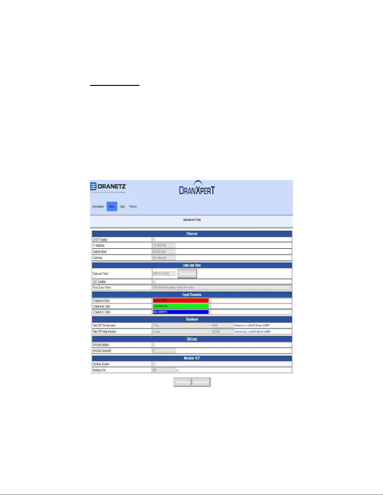
Instrument Setup
Select Setup > Instrument Setup to view/change the current instrument
setup. These are miscellaneous instrument settings, such as the
Ethernet settings, date/time, etc.
Note that the instrument setings can only be modified if monitoring is
OFF. If monitoring is ON, you will recive a warning that the survey
settings are “view only”.
32
Find Quality Products Online at: [email protected]
www.GlobalTestSupply.com
Page 33
Ethernet
DHCP – Checkbox enable/disable. If enabled, an IP address will be
automatically assigned to the instrument by the network. The IP address
assigned can be viewed in the Home/Instrument Status page.
IP Address – Instrument static IP address. The default static IP address
is: 192.168.0.40. Enter a valid IP address for the network being used.
Subnet Mask – Network subnet mask. The default is 255.255.255.0.
Enter a valid subnet mask for the network being used.
Gateway – Network gateway setting. Enter a valid gateway for the
network being used.
Date and Time
Note: The time and date of data stored in the DranXperT database is
recorded in UTC time. By setting the local time zone offset (below), the
data will appear in DranXperT and Dran-View XP in the local time zone.
Date and Time – Click in the date/time entry area to open up a dialog
box to enter the local time and date. Click the Change Date/Time button
when completed.
DST Enable – Checkbox enable/disable. Enable or disable Daylight
Savings Time.
Time Zone Offset – Dropdown. Select the local time zone.
Input Channels (LED colors)
You can change the color of the connector panel LEDs to match the
circuit’s wire colors.
Channel A Color – Dropdown list. Default channel A LED color is RED.
Channel B Color – Dropdown list. Default channel B LED color is
YELLOW.
Channel C Color – Dropdown list. Default channel C LED color is BLUE.
Database
Max DB File Seconds – Set the duration of the data file in hours, days,
weeks, or months from a dropdown list. The default setting is 31 days.
33
Find Quality Products Online at: [email protected]
www.GlobalTestSupply.com
Page 34

You can also enter a custom setting in seconds (<1hr). This setting is
how long the instrument will record until a new data file is automatically
created. A new data file will automatically be created when the duration
is exceeded.
Max DB Keep – Set the duration of time that the data file will be retained
in memory in days, weeks, months, or years from a dropdown list. You
can also enter a custom setting in minutes. This setting is the length of
time that the data file is retained in instrument memory before it is
marked for deletion from the database automatically. Data files older
than this setting will be automatically deleted to free up space for new
recordings.
BACnet
BACnet Enable – Checkbox enable/disable.
BACnet Device ID – Enter a valid BACnet Device ID for the instrument.
Modbus TCP
Modbus Enable – Checkbox enable/disable.
Modbus Port – Enter a valid modbus port. The default Modbus port is
502.
Submit Changes
When the Instrument Setups have been completed, click the Submit
Changes button to save the settings. Click the Discard Changes button
to discard the settings.
34
Find Quality Products Online at: [email protected]
www.GlobalTestSupply.com
Page 35
Download Config
Select Setup > Download Config to download the instrument settings to
your computer. This capability allows you to store a settings template for
your surveys that can be uploaded back into the instument for future use.
When selecting Download Config, two choices are available:
CfgActive.json (instrument settings file)
Cfg9000.json (for factory and advanced use)
Select the CfgActive.json option to download the current instrument
settings to your computer via your web browser’s file download feature.
When prompted, select “Save” or “Save as” in your web browser. The file
will be stored on your computer in the folder where your web browser
saves downloaded files. The instrument settings file saved will be named
“Survey Name.json”, where Survey Name is the survey name that you
programmed. Once saved to your computer, this file can renamed.
Upload Configuration
Select Setup > Upload Config to upload a settings file that was
previously downloaded (see above).
It is recommended that before uploading a setup file, the default
“CfgActive.json” file in the instrument should be saved in case of any
errors encountered with the uploaded file.
35
Find Quality Products Online at: [email protected]
www.GlobalTestSupply.com
Page 36

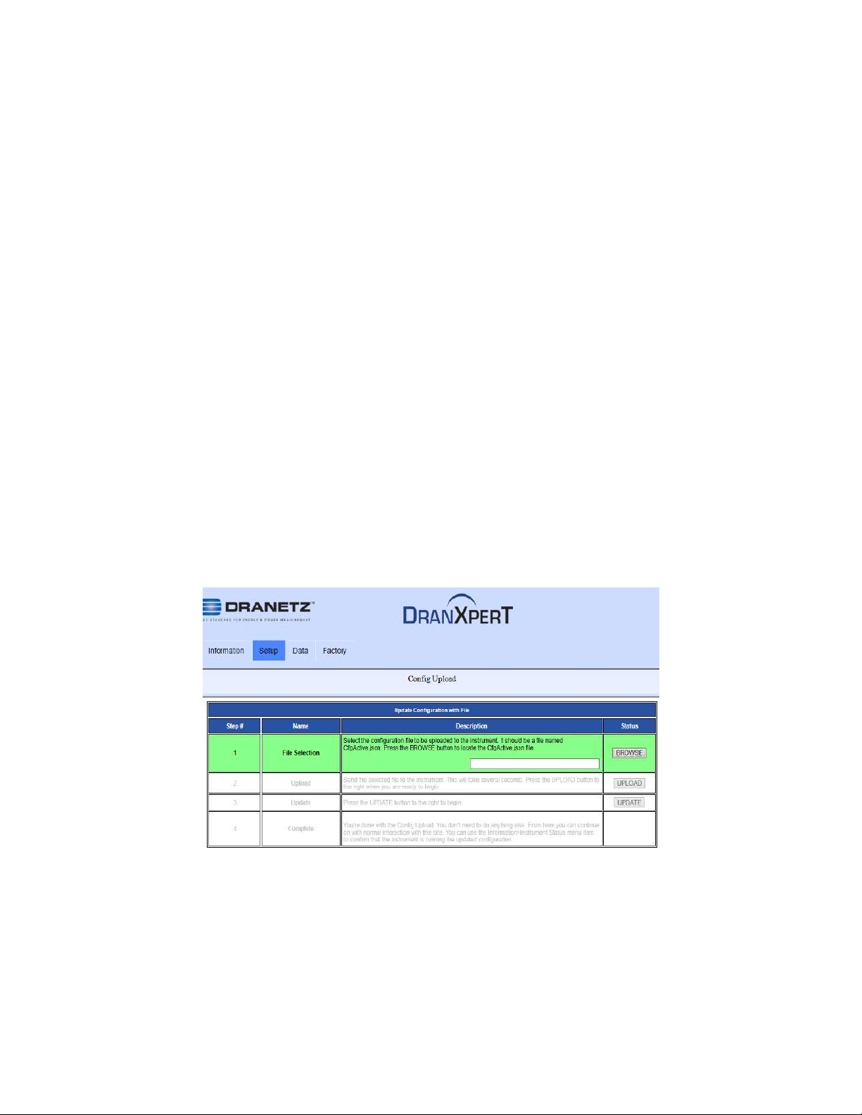
As shown in the image, there are 4 steps to upload settings files to the
instrument. Each step is highlighted in GREEN as you progress through
the process:
1) File Selection – Click the BROWSE button to path to the
configuration file to upload. Select the file and click Open.
2) Upload – Click the UPLOAD button to transfer the configuration
file to the instrument.
3) Update – Click the UPDATE button to save the configuration
information into the instrument.
4) Complete – When Complete is highlighted, uploading the
configuration has been succesfully completed.
Real-Time Measurements
Select Data > Meters to view the real-time metering information.
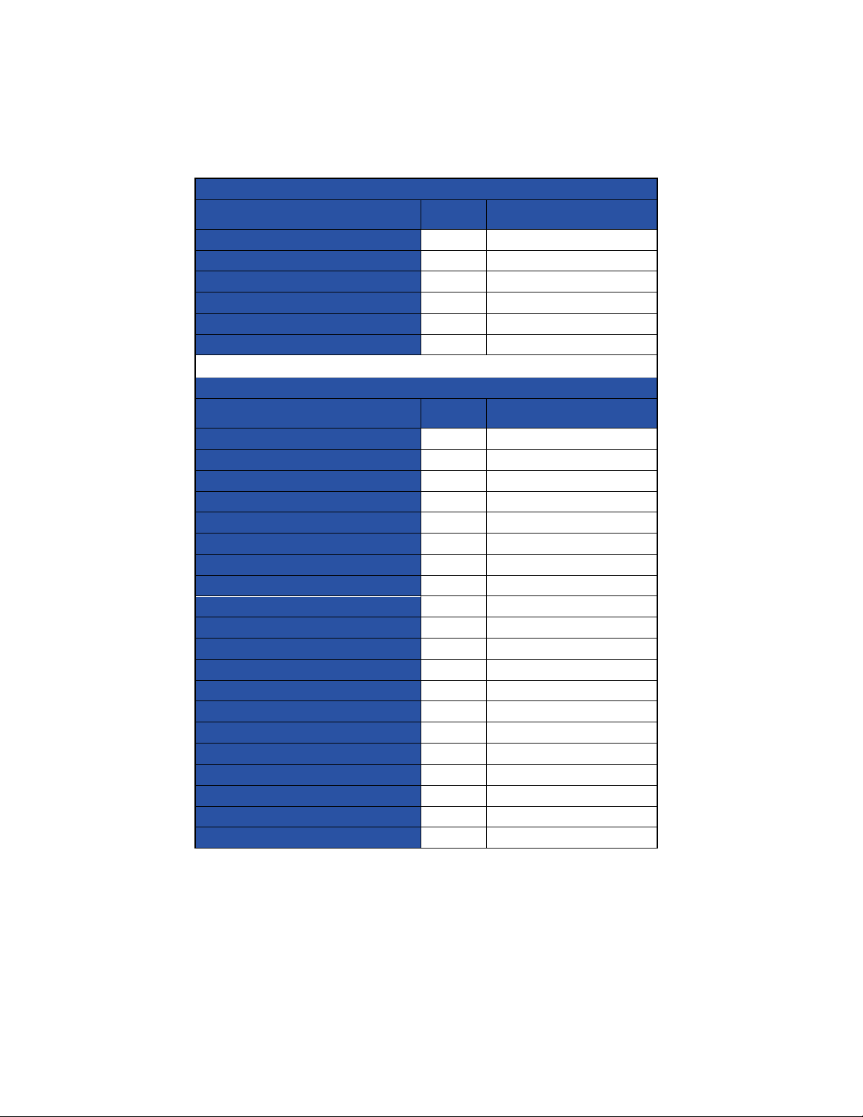
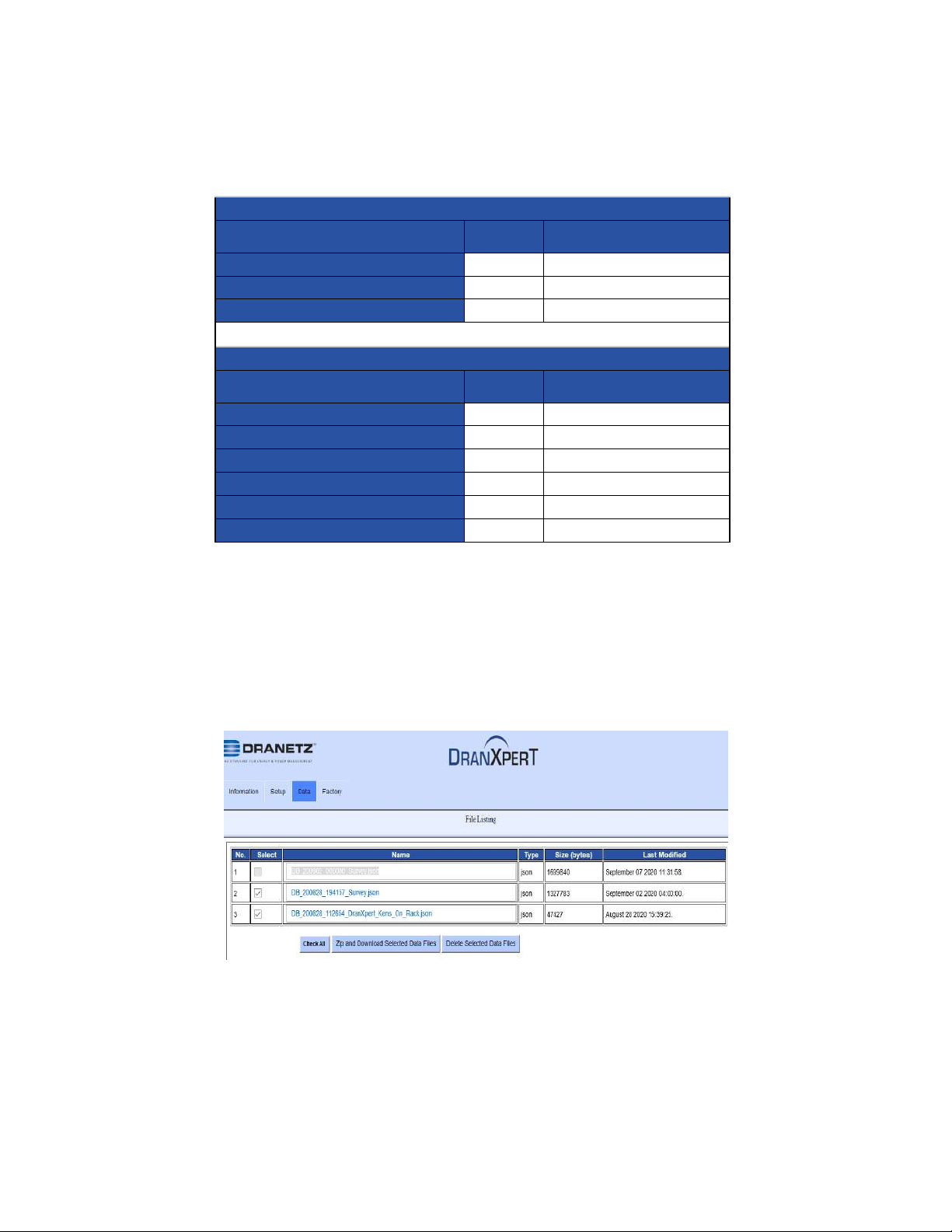
Real-time measurements are updated about every 5 seconds. The table
as follows lists the real-time parameters displayed and their units.
36
Find Quality Products Online at: [email protected]
www.GlobalTestSupply.com
Page 37
Energy
Description
Units
Channel (wiring dependent)
True Energy
Whr
A, B, C
Reactive Energy
VArhr
A, B, C
Apparent Energy
VAhr
A, B, C
True Energy (Fundamental)
Whr
A, B, C
Reactive Energy (Fundamental)
VArhr
A, B, C
Apparent Energy (Fundamental)
VAhr
A, B, C
Power
Description
Units
Channel (wiring dependent)
Frequency
Hz
A, B, C
RMS Voltage
VRMS
A, B, C
RMS Current
IRMS
A, B, C
True Power
W
A, B, C
Apparent Power
VA
A, B, C
Reactive Power
VAr
A, B, C
Power Factor
A, B, C
Voltage THD
%
A, B, C
Current THD
%
A, B, C
RMS Voltage (Fundamental)
VRMS
A, B, C
RMS Current (Fundamental)
IRMS
A, B, C
True Power (Fundamental)
W
A, B, C
Apparent Power (Fundamental)
VA
A, B, C
Reactive Power (Fundamental)
VAr
A, B, C
RMS Voltage (1 sec avg)
VRMS
A, B, C
RMS Current (1 sec avg)
IRMS
A, B, C
RMS Voltage (10/12 cycle)
VRMS
A, B, C
RMS Current (10/12 cycle)
IRMS
A, B, C
Voltage Phase
Deg.
A, B, C
Current Phase
Deg.
A, B, C
37
Find Quality Products Online at: [email protected]
www.GlobalTestSupply.com
Page 38
Neutral
Description
Units
Channel (wiring dependent)
Neutral RMS Current
IRMS
N
Neutral RMS Current (1 sec avg)
IRMS N Neutral RMS Current (10/12 cycle)
IRMS
N
Demand
Description
Units
Channel (wiring dependent)
Peak Demand
W
A, B, C
Peak Reactive Demand
VAr
A, B, C
Peak Apparent Demand
VA
A, B, C
Peak Demand (Fund.)
W
A, B, C
Peak Reactive Demand (Fund.)
VAr
A, B, C
Peak Apparent Demand (Fund.)
VA
A, B, C
Downloading and Managing Data
Select Data > List Files to view the recorded data files in the instrument’s
memory. The List Files page allows you to download data recorded by
DranXperT to your computer for analysis using Dran-View XP, and to
also delete files that are no longer needed.
38
Find Quality Products Online at: [email protected]
www.GlobalTestSupply.com
Page 39

Downloading data files
To download data files to your computer:
1) Check the file(s) to download or click the Check All button to
select all data files.
2) Click the Zip and Download Selected Data Files button to
download the selected files. The Zip feature will combine (zip
and compress) multiple files into one file for downloading.
3) DranXperT will display a progress window, and when completed,
your web browser will prompt you to open or save the zip file.
Click Save (or Save As) to save the file to your web browser’s
Download folder (name and location are browser-dependant).
4) Once the zip file has been downloaded, you can then move the
file to another location on your computer, network, or transfer via
email or FTP to another computer.
39
Find Quality Products Online at: [email protected]
www.GlobalTestSupply.com
Page 40

To unzip data files using the Windows unzip function:
1) Locate the zip file downloaded above. This is usually in your web
browser’s Download folder.
2) Right-click on the file and select Extract All. The window below
will be displayed.
3) Click the Browse button to choose or create the folder where the
extracted data files will be saved.
4) Click Extract to save the DranXperT files to the location chosen
in step #3. Note that DranXperT data files are of the file type
“.json”.
5) When the above is completed, the DranXperT data is ready to be
viewed by Dran-View XP. See the View Recorded Data section
below.
Deleting data files from DranXperT’s memory
1) Check the file(s) to delete or click the Check All button to select
all data files.
2) Click the Delete Selected Data Files button.
3) When prompted, click OK to delete the selected files or Cancel
to abort.
40
Find Quality Products Online at: [email protected]
www.GlobalTestSupply.com
Page 41
Factory Settings
Instrument Firmware
Dranetz continually provides updates to our products to enchance their
capabilities and to correct known issues. These updates are available for
download on our website. It is always good practice to periodically check
to make sure that your instrument is up to date.
The firmware version of your instrument can be found on the Instrument
Status page. Dranetz product firmware updates and information can be
found here:
If the firmware posted on our website is newer than what is installed in
your instrument, please follow the online instructions to download the
firmware update. Then, follow the firmware installation instructions below
to update your instrument.
Firmware Updates
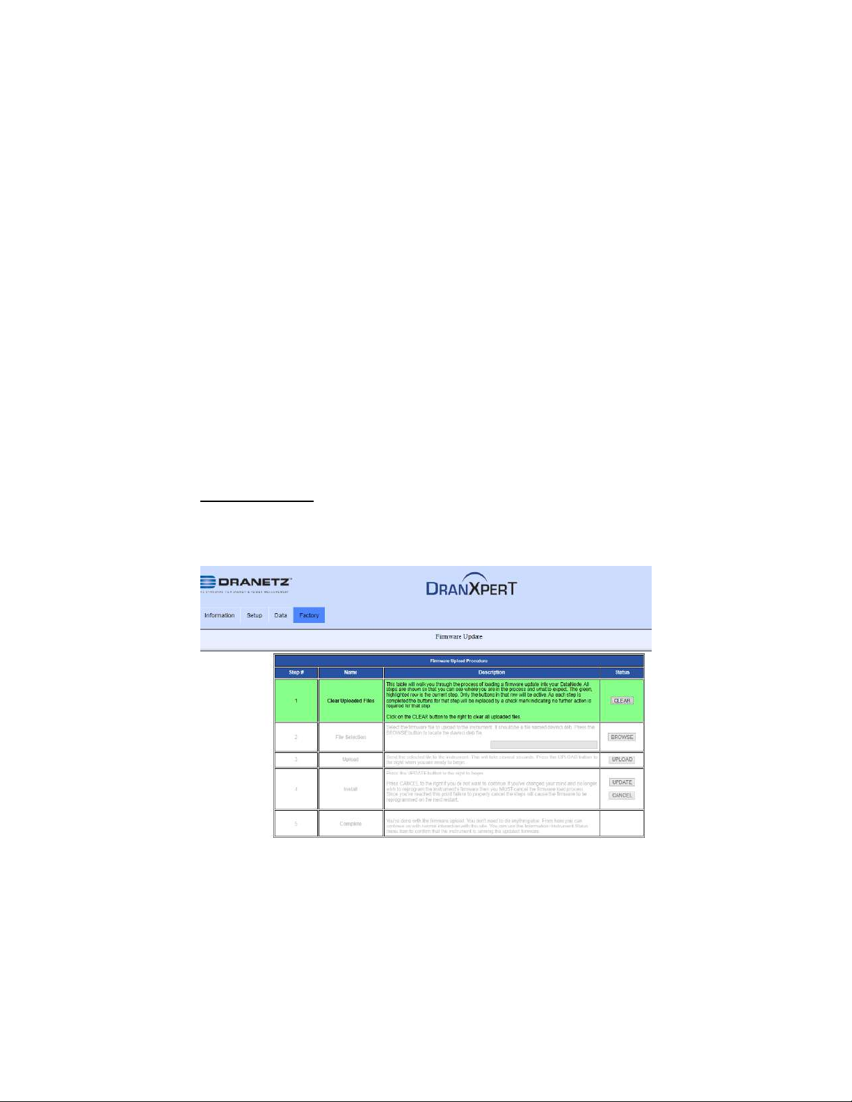
Select Factory > Update Firmware to update DranXperT’s firmware. The
page shown below will be displayed.
41
Find Quality Products Online at: [email protected]
www.GlobalTestSupply.com
Page 42

Follow the steps below to upgrade DranXperT’s firmware. The firmware
update wizard will guide you through the process. The current step is
highlighted in GREEN as shown in the picture above. Once a step is
completed the next step will be highlighted.
1) Click the Clear button to clear previously updated firmware.
2) Click Browse to locate the firmware update file that you
downloaded from the Dranetz website. Note that DranXperT
firmware files have a ‘.deb’ file extension. Select the firmware file
and click Open.
3) Click the Upload button to upload the firmware update file to
DranXperT.
4) Click the Update button to begin the firmware update process or
click Cancel to abort.
5) When the firmware update process has completed, step #5 will
be highlighted in GREEN.
Please check the Information > Status page to verify that the version
displayed matches the new version installed.
Restore Factory Defaults
There may come a time when you need to restore DranXperT’s settings
to its factory defaults. There are several options. Select the “Factory” tab,
then choose the option below that best fits your needs:
Restore Factory Default (Keep IP) – Restore the factory settings
but keep the data and IP address settings as is (unchanged).
Restore Factory Default with Data Purge (Keep IP) – Restore the
factory settings and purge all data, but keep the IP address
settings as is (unchanged).
Restore All Settings to Factory Default (incl. IP) – Restore all
factory settings including the IP address, and also purge the
data.
Note: Depending on the option chosen above, instrument
settings, recorded data, and/or the IP address will be
deleted from the instrument.
After selecting one of the options described above, you will be prompted
to confirm that you would like to proceed. Click the OK button to continue
or click Cancel to abort.
42
Find Quality Products Online at: [email protected]
www.GlobalTestSupply.com
Page 43
Restart
There may come a time when you need to restart the instrument.
Restarting will reboot the instrument, and when completed, the
instrument will resume monitoring if monitoring was previously turned on.
No settings or data files are lost when restarting.
To restart the instrument, select Factory > Restart.
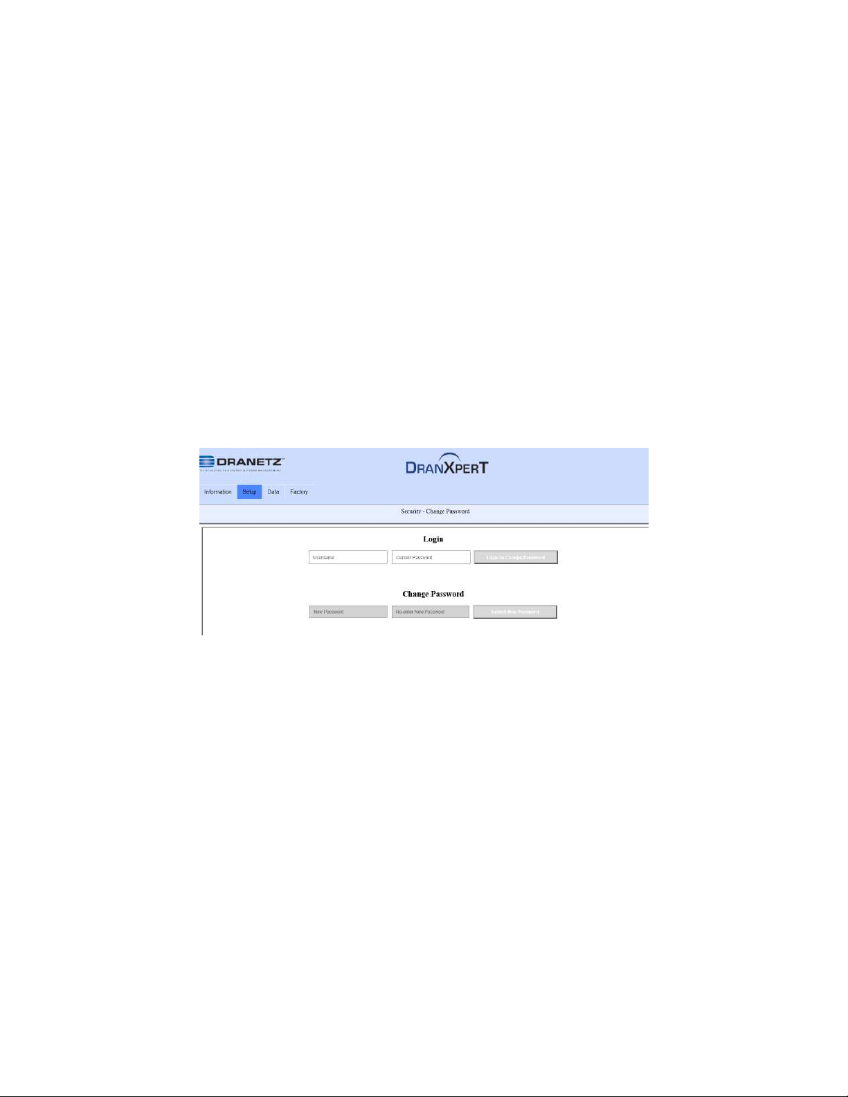
Change Password
The default username and password for DranXperT are listed above in
the Connecting to DranXperT section. The username cannot be
changed, but the password can be changed.
To change the password, select Factory > Change Password. The page
below will appear.
Enter the current username and pasword in the Login field and click
Login to Change Password.
Enter the new password in the both the New Password and Password
Confirmation fields and click Submit New Password.
43
Find Quality Products Online at: [email protected]
www.GlobalTestSupply.com
Page 44
START/STOP MONITORING
Monitoring can be started or stopped by using either the membrane
keypad or via a web browser.
Start Monitoring
Once you have configured the DranXperT settings, the next step is to
start monitoring. Please do one of the following to start monitoring:
Instrument Keypad
Press and hold the “Monitoring” button for approximately 5
seconds until a beep is heard to turn monitoring ON. The LED
above the button will illuminate “GREEN” when monitoring has
started and is ON.
Web Browser
Select the Information > Status page. At the bottom of the page,
click Turn On Monitoring. When monitoring is ON, the button text
will change to “Turn Off Monitoring”.
44
Find Quality Products Online at: [email protected]
www.GlobalTestSupply.com
Page 45
Stop Monitoring
Please do one of the following to stop monitoring.
Instrument Keypad
Press and hold the “Monitoring” button for approximately 5
seconds until a beep is heard to turn monitoring OFF. The
“Monitor” LED will turn OFF when monitoring is stopped.
Web Browser
Select the Information > Status page. At the bottom of the page
click Turn OFF Monitoring. When monitoring is OFF, the button
text will change to “Turn On Monitoring”.
45
Find Quality Products Online at: [email protected]
www.GlobalTestSupply.com
Page 46

VIEWING RECORDED DATA
DranXperT data files are stored in a json (JavaScript Object Notation) file
format and have a “.json” file extension. Dran-View XP software is used
to view and analyze data recorded by DranXperT. In order to do so, you
must first copy the DranXperT data files to your computer. Please follow
the steps below:
Copying Data from DranXperT
There are 2 ways to copy data to your computer for analysis using DranView XP software.
1) Download data to a computer using your web browser – see the
Downloading and Managing Data section above.
2) USB drive – DranXperT data can be automatically copied to a
USB drive by following the steps below:
a. Turn off monitoring – see the Start/Stop Monitoring
section above. Data cannot be copied to a USB drive
when monitoring is ON.
b. Insert a USB drive into the USB port.
c. DranXperT will automatically begin copying all data files
to the USB drive. The 6 measurement input LEDs will
blink GREEN while data is being transferred to the USB
drive.
d. The data transfer has completed when the measurement
input LEDs stop blinking GREEN.
e. When the transfer is complete, remove the USB drive
from DranXperT.
f. Insert the USB drive into a USB port of the computer
running Dran-View XP and then follow the instructions
below to open a data file.
Opening Data in Dran-View XP
To view data files in Dran-View XP:
1) Start Dran-View XP.
2) Select “File” and then select “Open”.
3) Locate and select the data file of interest and select “Open”. The
data file can be located on your computer, external USB drive,
network folder, etc.
46
Find Quality Products Online at: [email protected]
www.GlobalTestSupply.com
Page 47
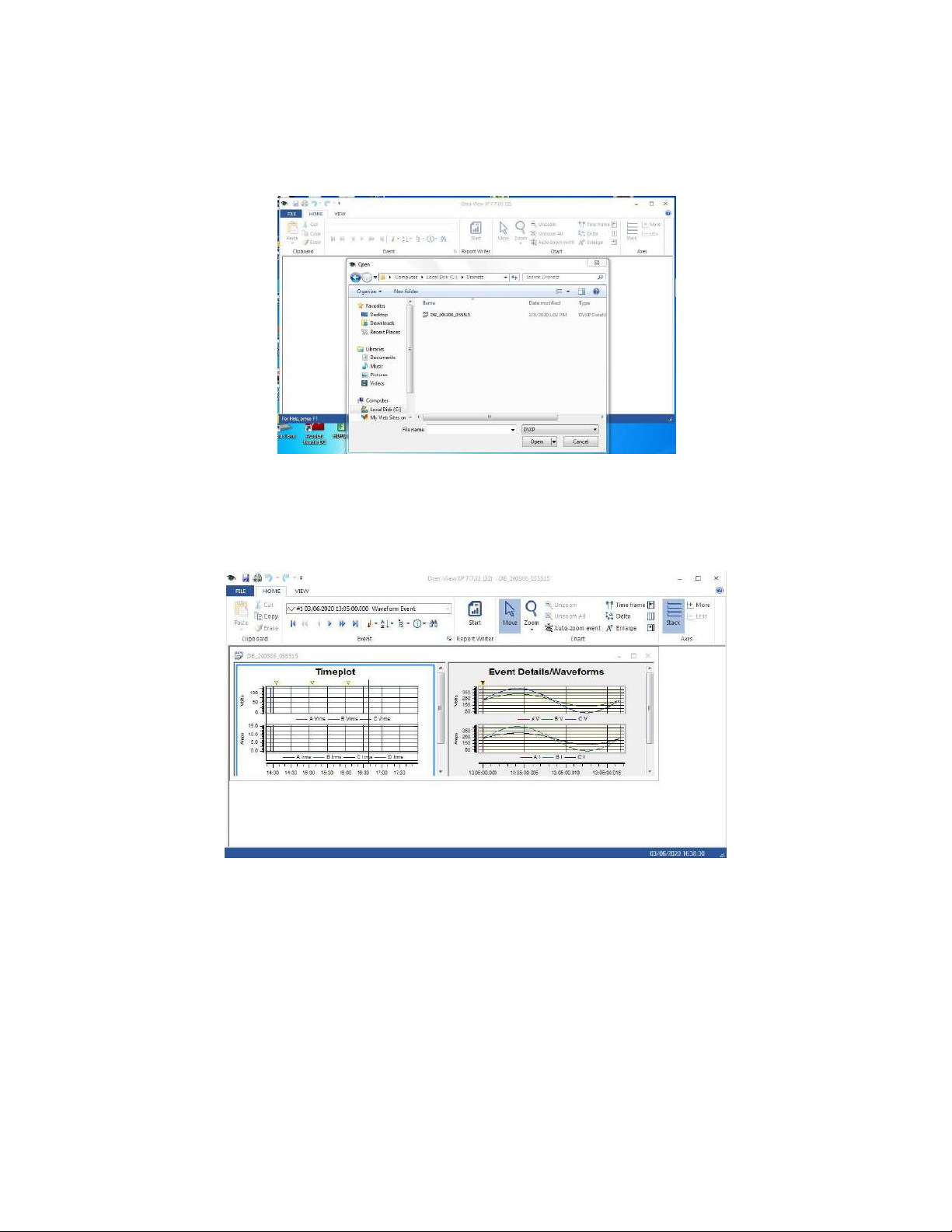
Once the data file is opened, Dran-View XP will display the data
recorded by DranXperT. You can view Time Plots, Event details, and
more for analysis and reporting.
47
Find Quality Products Online at: [email protected]
www.GlobalTestSupply.com
Page 48
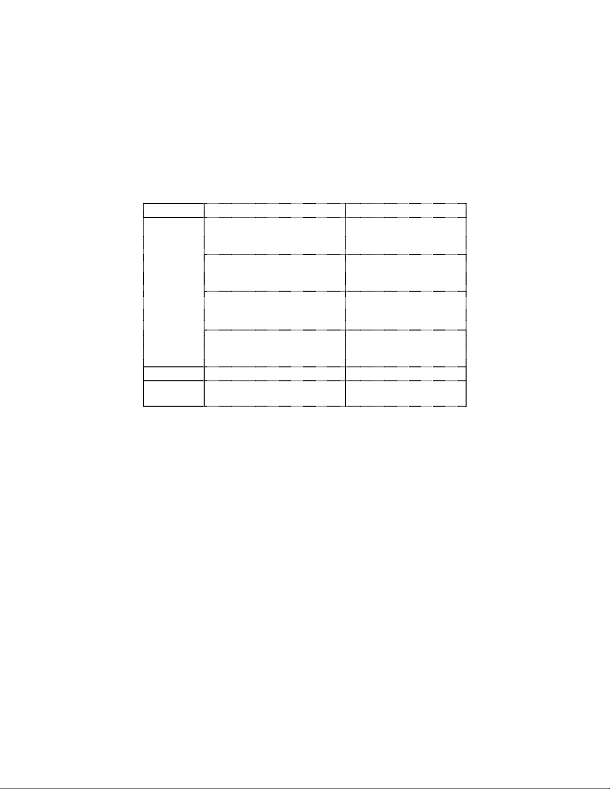
Qty
Description
Part Number
1
(universal
input
power
supply and
choice of
one power
cord
supplied
with each
instrument)
External Power Supply
(+5V output) and US 115V
power cord
DRANXPERT-PS-US
External Power Supply
(+5V output) and European
Schuko 250V power cord
DRANXPERT-PS-EU
External Power Supply
(+5V output) and United
Kingdom 250V power cord
DRANXPERT-PS-UK
External Power Supply
(+5V output) and Australian
250V power cord
DRANXPERT-PS-AU
1
Voltage Cable Set
118918-G1
1
DranXperT
Quick Reference Guide
QR-DRANXPERT
Standard Accessories
ACCESSORIES LIST
The following table lists the standard accessories for DranXperT.
Find Quality Products Online at: [email protected]
www.GlobalTestSupply.com
48
Page 49
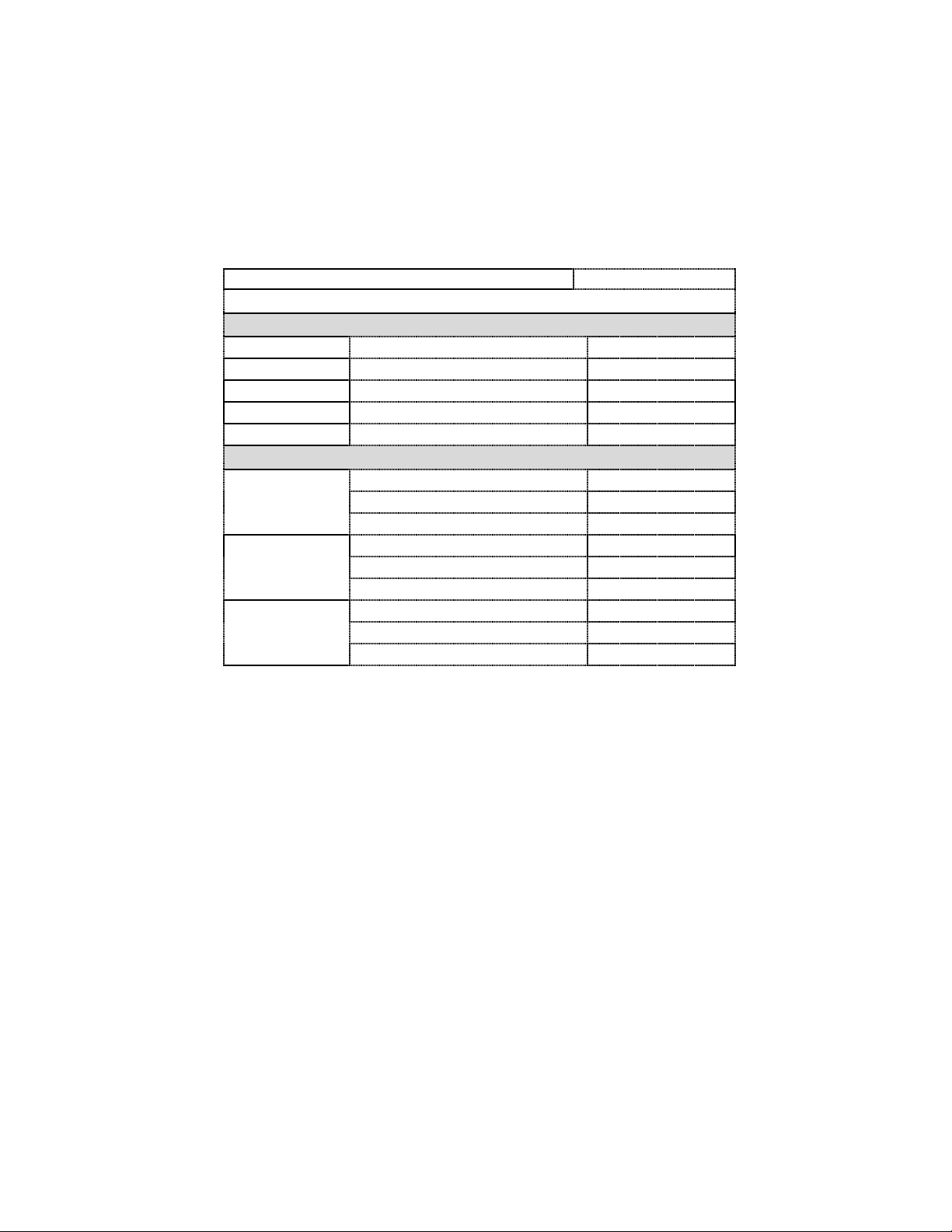
Optional Accessories
Description
Part Number
Current Probe Accessories
Hinged, Split - Core Current Probes. 600V CAT III
5A
0.4 in (10 mm) window size
CT-H-5A
20A
0.4 in (10 mm) window size
CT-H-20A
50A
0.4 in (10 mm) window size
CT-H-50A
100A
1 in (25.4 mm) window size
CT-H-100A
600 A
1.38 in (35.1 mm) window size
CT-H-600A
Rogowski – Flexible Coil Current Probes. 1000V CAT III
50A – 500A
4.17 in (106 mm) window size
FLEX-500A-16
7.01 in (178 mm) window size
FLEX-500A-24
10.67 in (271 mm) window size
FLEX-500A-36
150A – 1500A
4.17 in (106 mm) window size
FLEX-1500A-16
7.01 in (178 mm) window size
FLEX-1500A-24
10.67 in (271 mm) window size
FLEX-1500A-36
300A – 3000A
4.17 in (106 mm) window size
FLEX-3000A-16
7.01 in (178 mm) window size
FLEX-3000A-24
10.67 in (271 mm) window size
FLEX-3000A-36
The following table lists the optional accessories for DranXperT.
Note:
The DranXperT only supports current probes of the same type for all
current input channels. When measuring current parameters, the same
probe type has to be connected to each channel you are monitoring.
49
Find Quality Products Online at: [email protected]
www.GlobalTestSupply.com
Page 50

SPECIFICATIONS*
GENERAL
Sampling Frequency: 32ksps (recorded and real-time meters),
128 samples per cycle (periodic waveform snapshots)
Sag/dip, swell trigger resolution: 1-cycle (uses IEC 61000-4-30
Class S methods)
Panel indicators: RGB LEDs for monitoring on/off, energy flow,
PQ event indication, battery charging/status, wiring status
Storage Capacity: 8GB
UL, CE
Voltage (3)
Range: 90 to 600VRMS CATIII
Accuracy: 90 VRMS to 600VRMS = ±0.1%, <90 VRMS = 0.5%
Connections: 4 safety banana voltage inputs – 3-phase voltage
and 1 neutral/reference
Current (4)
Input: 0.333 VRMS full scale, Connections: BNC
Accuracy: ±0.1% + probe
Frequency
Range: 50Hz = 45Hz to 55Hz, 60Hz = 55Hz to 65Hz
Accuracy: 50/60Hz: ±0.001Hz
POWER QUALITY
Sag/dip, swell trigger threshold resolution: 1-cycle
Vthd: ±5% for V ≥ 10% Vnom
Ithd: ±5% for I ≥ 10% Inom + probe error
ENERGY PARAMETERS (probe dependent)
(True/Active) Energy (P): 0.1%
Reactive Energy (Q): 0.1%
Apparent Energy (S): 0.1%
Fundamental Active Energy(P): 0.2%
Fundamental Reactive Energy(Q): 0.2%
Fundamental Apparent Energy (S): 0.2%
Demand: 0.2%
50
Find Quality Products Online at: [email protected]
www.GlobalTestSupply.com
Page 51

POWER PARAMETERS (probe dependent)
(True/Active) Power (P): 0.2%
Reactive Power (Q): 0.2%
Apparent Power (S: 0.2%
Fundamental Active Power(P): 0.2%
Fundamental Reactive Power (Q): 0.2%
Fundamental Apparent Power (S): 0.2%
Power Factor (PF): ±0.001%
INSTRUMENT POWER
Line Power Supply
Range: 90 to 264 VAC, 47 to 63Hz, Consumption: 15W max
Line cords/plugs: Localized – US, EU, UK, Australia available
Internal Battery
Rechargeable lithium Ion battery pack (UL recognized)
Run time: 7 hours (typical), Charge time: 15 hours (typical)
COMMUNICATION INTERFACES
Ethernet: 10
USB: 2.0
Protocols: Modbus, Bacnet
ENCLOSURE & MECHANICAL
Mechanical
Weight: 1.4 lb. (0.64Kg)
Dimensions: 3.5” W x 2.2” H x 7.4” L (6.4 cm x 8.9 cm x 18.8cm)
IP50 (vertical position)
Environmental
Storage Temperature: 5 to 131 °F (-15 to +55 °C)
Operating Temperature: 32 to 113 °F (0 to +45 °C)
Humidity: 5% to 95% non-condensing
Altitude
2000m (6560 ft) maximum
Installation Categories
Mains Supply: 100-240V, CAT II, Pollution Degree 2
Measurement: Inputs 600 VRMS, CAT III, Pollution Degree 2
* Notes:
Specifications are subject to change without notice
Dranetz recommends annual calibration to maintain the specified
accuracies
51
Find Quality Products Online at: [email protected]
www.GlobalTestSupply.com
Page 52

STATEMENTS AND NOTICES
Statement of Warranty
All Dranetz manufactured portable instruments and accessories are
warranted to the original purchaser against defective material and
workmanship for a period of three years from the date of invoice. User
replaceable instrument batteries are warranted for a period of one year
from the date of invoice. Certain Dranetz branded accessories, such as
current transformers and other accessories not manufactured by
Dranetz, are warranted to the original purchaser against defective
material and workmanship for a period of one year from the date of
invoice. Warranties for products and accessories sold by, but not
branded as Dranetz, are covered by their respective manufacturer’s
warranties, and are not warranted by Dranetz. Dranetz will repair or
replace, at its option, all defective equipment that is returned, freight
prepaid, during the warranty period. There will be no charge for repair,
provided there is no evidence that the equipment has been mishandled
or abused. This warranty shall not apply to any defects resulting from
improper or inadequate maintenance, buyer-supplied hardware/software
interfacing, unauthorized modification or misuse of the equipment,
operation outside of environmental specifications, or improper site
preparation or maintenance.
Statement of Reliability
The information in this Quick Reference Guide has been reviewed and is
believed to be entirely reliable. However, no responsibility is assumed for
any inaccuracies. All material is for informational purposes only, and is
subject to change without prior notice.
Notice Regarding FCC Compliance
This device has been tested and found to comply with the limits for a
Class A digital device, pursuant to Part 15 of the FCC Rules. These
limits are designed to provide reasonable protection against harmful
interference when the equipment is operated in a commercial
environment. This equipment generates, uses, and can radiate radio
frequency energy and, if not installed and used in accordance with the
instruction manual, may cause harmful interference to radio
communications. Operation of this equipment in a residential area is
likely to cause harmful interference in which case the user will be
required to correct the interference at his/her own expense.
52
Find Quality Products Online at: [email protected]
www.GlobalTestSupply.com
Page 53

Statements and Notices (cont.)
Notice Regarding Proprietary Rights
This publication contains information proprietary to Dranetz. By
accepting and using this Quick Reference Guide, you agree that the
information contained herein will be used solely for the purpose of
operating equipment of Dranetz.
Copyright
This publication is protected under the Copyright laws of the United
States, Title 17 et seq. No part of this publication may be reproduced,
transmitted, transcribed, stored in a retrieval system, or translated into
any language or computer language, in any form, by any means,
electronic, mechanical, magnetic, optical, chemical, manual, or
otherwise, without the prior written consent of Dranetz, 1000 New
Durham Road, Edison, New Jersey 08817.
Copyright © 2021 Dranetz
All Rights Reserved. Printed in the United States of America.
Trademarks
Dranetz DRANXPERT® and DRAN-VIEW® are registered trademarks of
Dranetz.
Other trademarks and trade names are those of their respective owners.
53
Find Quality Products Online at: [email protected]
www.GlobalTestSupply.com
 Loading...